Roadway Design Geopak Help Manual Shapes - Mississippisp.mdot.ms.gov/Roadway...
33
Roadway Design Geopak Help Manual Shapes RWD CADD Support (10-1-2010)
Transcript of Roadway Design Geopak Help Manual Shapes - Mississippisp.mdot.ms.gov/Roadway...
Roadway Design Geopak Help Manual
Shapes
RWD CADD Support (10-1-2010)
Doc-To-Help Standard Template Contents i
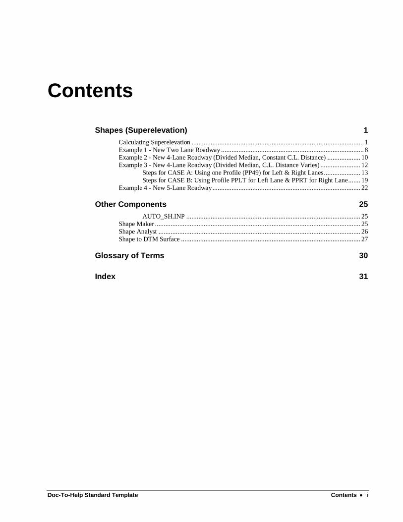
Contents
Shapes (Superelevation) 1
Calculating Superelevation ................................................................................................... 1 Example 1 - New Two Lane Roadway .................................................................................. 8 Example 2 - New 4-Lane Roadway (Divided Median, Constant C.L. Distance) ................... 10 Example 3 - New 4-Lane Roadway (Divided Median, C.L. Distance Varies) ....................... 12
Steps for CASE A: Using one Profile (PP49) for Left & Right Lanes ..................... 13 Steps for CASE B: Using Profile PPLT for Left Lane & PPRT for Right Lane ....... 19
Example 4 - New 5-Lane Roadway ..................................................................................... 22
Other Components 25
AUTO_SH.INP .................................................................................................... 25 Shape Maker ...................................................................................................................... 25 Shape Analyst .................................................................................................................... 26 Shape to DTM Surface ....................................................................................................... 27
Glossary of Terms 30
Index 31
Doc-To-Help Standard Template Shapes (Superelevation) 1
Shapes (Superelevation)
Calculating Superelevation Before templates can be created for a BASELINE the slopes of the parallel lanes related to that baseline must be defined. Geopak describes a shape as an area of constant slope or an area of superelevation transition. A SHAPE CLUSTER is one or more shapes that represent the same BASELINE or PGL and the same PROFILE. These shapes are plotted in a design file and read when running Templates to produce the Pavement Part of the Template. Steps for calculating Superelevation and creating Shapes:
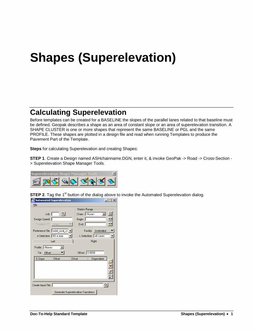
STEP 1. Create a Design named ASHchainname.DGN, enter it, & invoke GeoPak -> Road -> Cross-Section -> Superelevation Shape Manager Tools.
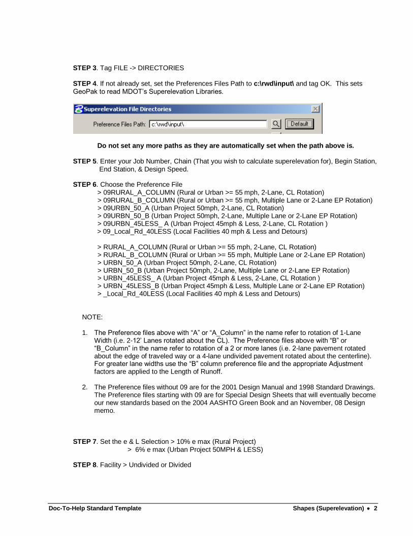
STEP 2. Tag the 1st button of the dialog above to invoke the Automated Superelevation dialog.
Doc-To-Help Standard Template Shapes (Superelevation) 2
STEP 3. Tag FILE -> DIRECTORIES STEP 4. If not already set, set the Preferences Files Path to c:\rwd\input\ and tag OK. This sets GeoPak to read MDOT’s Superelevation Libraries.
Do not set any more paths as they are automatically set when the path above is. STEP 5. Enter your Job Number, Chain (That you wish to calculate superelevation for), Begin Station, End Station, & Design Speed. STEP 6. Choose the Preference File > 09RURAL_A_COLUMN (Rural or Urban >= 55 mph, 2-Lane, CL Rotation) > 09RURAL_B_COLUMN (Rural or Urban >= 55 mph, Multiple Lane or 2-Lane EP Rotation) > 09URBN_50_A (Urban Project 50mph, 2-Lane, CL Rotation) > 09URBN_50_B (Urban Project 50mph, 2-Lane, Multiple Lane or 2-Lane EP Rotation) > 09URBN_45LESS_ A (Urban Project 45mph & Less, 2-Lane, CL Rotation ) > 09_Local_Rd_40LESS (Local Facilities 40 mph & Less and Detours) > RURAL_A_COLUMN (Rural or Urban >= 55 mph, 2-Lane, CL Rotation) > RURAL_B_COLUMN (Rural or Urban >= 55 mph, Multiple Lane or 2-Lane EP Rotation) > URBN_50_A (Urban Project 50mph, 2-Lane, CL Rotation) > URBN_50_B (Urban Project 50mph, 2-Lane, Multiple Lane or 2-Lane EP Rotation) > URBN_45LESS_ A (Urban Project 45mph & Less, 2-Lane, CL Rotation ) > URBN_45LESS_B (Urban Project 45mph & Less, Multiple Lane or 2-Lane EP Rotation) > _Local_Rd_40LESS (Local Facilities 40 mph & Less and Detours) NOTE:
1. The Preference files above with “A” or “A_Column” in the name refer to rotation of 1-Lane
Width (i.e. 2-12’ Lanes rotated about the CL). The Preference files above with “B” or “B_Column” in the name refer to rotation of a 2 or more lanes (i.e. 2-lane pavement rotated about the edge of traveled way or a 4-lane undivided pavement rotated about the centerline). For greater lane widths use the “B” column preference file and the appropriate Adjustment factors are applied to the Length of Runoff.
2. The Preference files without 09 are for the 2001 Design Manual and 1998 Standard Drawings.
The Preference files starting with 09 are for Special Design Sheets that will eventually become our new standards based on the 2004 AASHTO Green Book and an November, 08 Design memo.
STEP 7. Set the e & L Selection > 10% e max (Rural Project) > 6% e max (Urban Project 50MPH & LESS) STEP 8. Facility > Undivided or Divided
Doc-To-Help Standard Template Shapes (Superelevation) 3
Set to Undivided for all facilities. For Divided facilities, you have to do these steps twice and create 2 Input files and leave this setting to Undivided.
STEP 9. Profile > Choose the related Proposed Profile STEP 10. Tie > Offset STEP 11. Offset > ?
Distance from specified Chain you want to place the Profile & rotate about. NOTE: Offset = 0 if you want the Profile to be placed at the chain_name
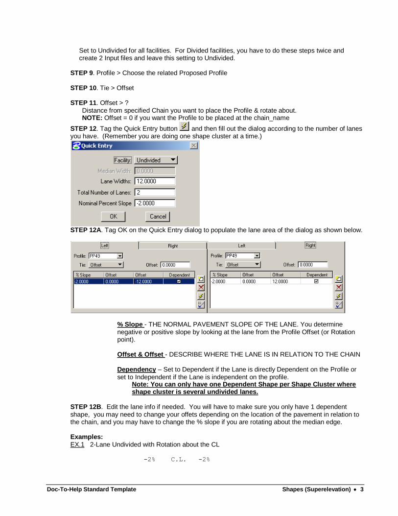
STEP 12. Tag the Quick Entry button and then fill out the dialog according to the number of lanes you have. (Remember you are doing one shape cluster at a time.)
STEP 12A. Tag OK on the Quick Entry dialog to populate the lane area of the dialog as shown below.
% Slope - THE NORMAL PAVEMENT SLOPE OF THE LANE. You determine negative or positive slope by looking at the lane from the Profile Offset (or Rotation point).
Offset & Offset - DESCRIBE WHERE THE LANE IS IN RELATION TO THE CHAIN
Dependency – Set to Dependent if the Lane is directly Dependent on the Profile or set to Independent if the Lane is independent on the profile.
Note: You can only have one Dependent Shape per Shape Cluster where shape cluster is several undivided lanes.
STEP 12B. Edit the lane info if needed. You will have to make sure you only have 1 dependent shape, you may need to change your offets depending on the location of the pavement in relation to the chain, and you may have to change the % slope if you are rotating about the median edge. Examples: EX.1 2-Lane Undivided with Rotation about the CL -2% C.L. -2%
Doc-To-Help Standard Template Shapes (Superelevation) 4
|-------------|-------------|
| | |
| 12' | 12' |
|<----------->|<----------->|
| INDEP | DEP | OFFSET = 0
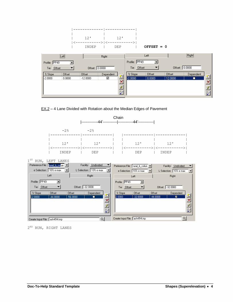
EX.2 – 4 Lane Divided with Rotation about the Median Edges of Pavement Chain |-------------44’-----------|------------44’------------| -2% -2% |-------------|-------------| |-------------|-------------|
| | | | | |
| 12' | 12' | | 12' | 12' |
|<----------->|<----------->| |<----------->|<----------->|
| INDEP | DEP | | DEP | INDEP |
1ST RUN, LEFT LANES
2ND RUN, RIGHT LANES
Doc-To-Help Standard Template Shapes (Superelevation) 5
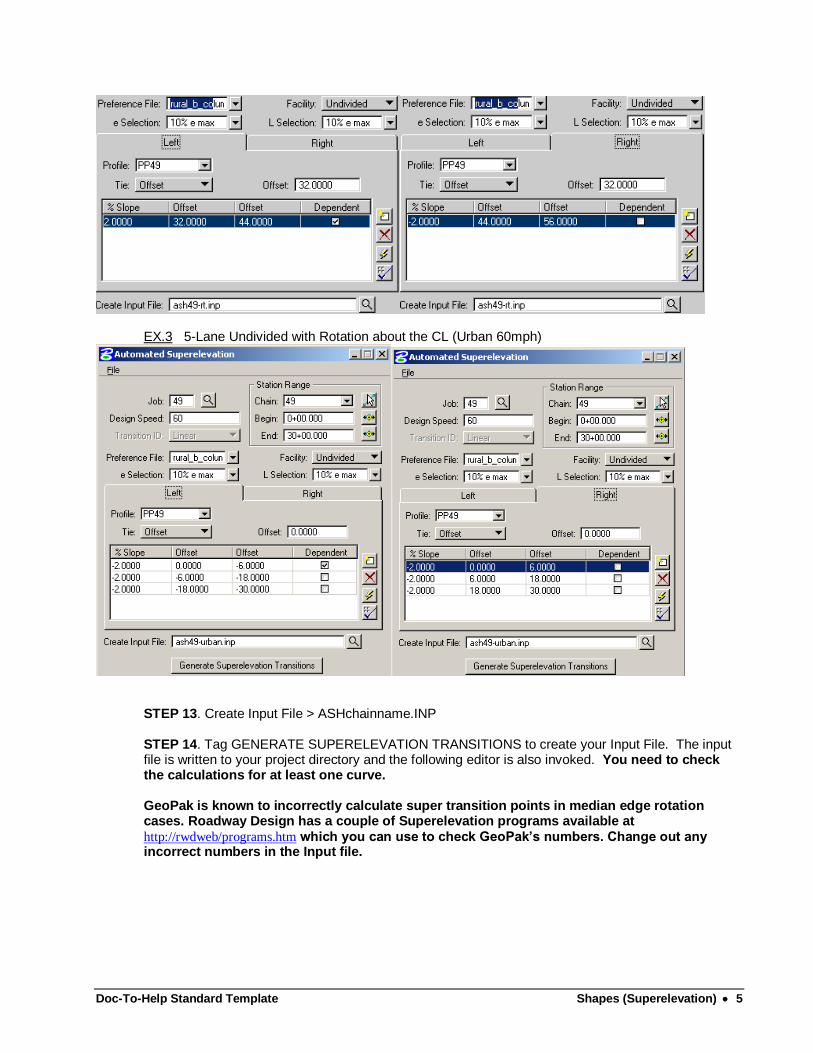
EX.3 5-Lane Undivided with Rotation about the CL (Urban 60mph)
STEP 13. Create Input File > ASHchainname.INP STEP 14. Tag GENERATE SUPERELEVATION TRANSITIONS to create your Input File. The input file is written to your project directory and the following editor is also invoked. You need to check the calculations for at least one curve. GeoPak is known to incorrectly calculate super transition points in median edge rotation cases. Roadway Design has a couple of Superelevation programs available at http://rwdweb/programs.htm which you can use to check GeoPak’s numbers. Change out any incorrect numbers in the Input file.
Doc-To-Help Standard Template Shapes (Superelevation) 6
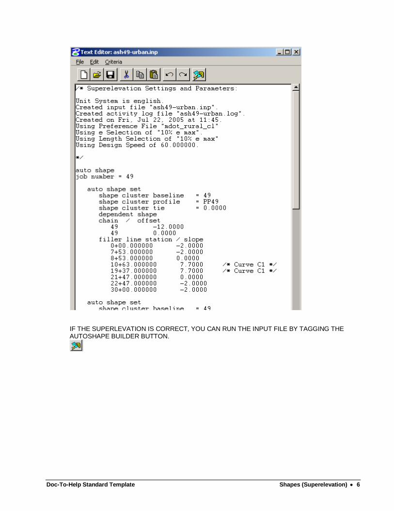
IF THE SUPERLEVATION IS CORRECT, YOU CAN RUN THE INPUT FILE BY TAGGING THE AUTOSHAPE BUILDER BUTTON.
Doc-To-Help Standard Template Shapes (Superelevation) 7
STEP 16. This Input file is set up for Lanes which are parallel to your Shape Cluster Baseline. To place shapes in tapered pavement areas you have three options available.
Option A - Define “Pavement Widening in DGN” when running Proposed X-Sections. The Proposed
X-Section Criteria files draw the TAPERED AREA THE SAME SLOPE AS THE PARALLEL PAVEMENT AREAS.
Option B - Place your tapered shapes with the SHAPE MAKER DIALOG BOX. Option C - Store your Edges of Pavement as Chains and change the Input File before running it. Option "A" is preferred because it cuts down on errors when running your Template Input file, but if the SLOPE OF THE TAPERED IS DIFFERENT THAN THE PARALLEL PAVEMENT AREAS use another option.
OPTION "A" (Normally for Local Roads)
STEP 16-c1. Use to run the Input file created in the steps above (from Applications>Geopak Road>other components in MicroStation).This step places the SHAPES in the design file. STEP 16-c2. Define “Proposed EP in DGN” when running Proposed X-Sections.
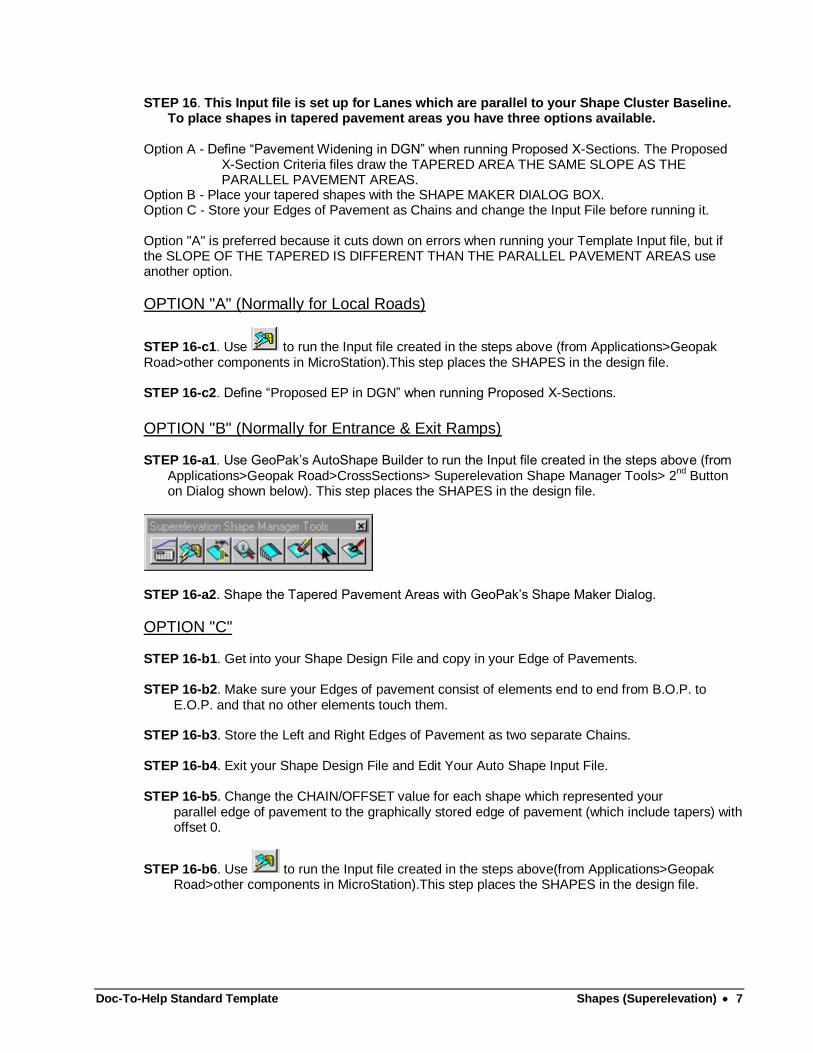
OPTION "B" (Normally for Entrance & Exit Ramps) STEP 16-a1. Use GeoPak’s AutoShape Builder to run the Input file created in the steps above (from
Applications>Geopak Road>CrossSections> Superelevation Shape Manager Tools> 2nd
Button on Dialog shown below). This step places the SHAPES in the design file.
STEP 16-a2. Shape the Tapered Pavement Areas with GeoPak’s Shape Maker Dialog.
OPTION "C" STEP 16-b1. Get into your Shape Design File and copy in your Edge of Pavements. STEP 16-b2. Make sure your Edges of pavement consist of elements end to end from B.O.P. to
E.O.P. and that no other elements touch them. STEP 16-b3. Store the Left and Right Edges of Pavement as two separate Chains. STEP 16-b4. Exit your Shape Design File and Edit Your Auto Shape Input File. STEP 16-b5. Change the CHAIN/OFFSET value for each shape which represented your
parallel edge of pavement to the graphically stored edge of pavement (which include tapers) with offset 0.
STEP 16-b6. Use to run the Input file created in the steps above(from Applications>Geopak Road>other components in MicroStation).This step places the SHAPES in the design file.
Doc-To-Help Standard Template Shapes (Superelevation) 8
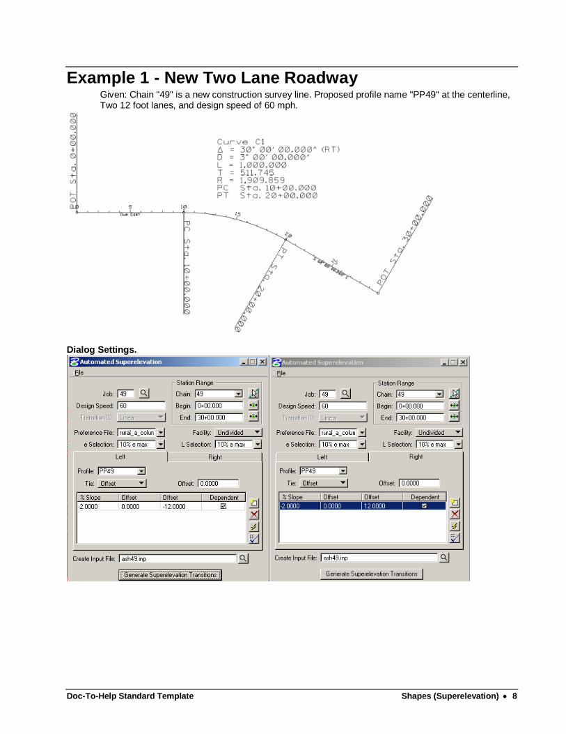
Example 1 - New Two Lane Roadway Given: Chain "49" is a new construction survey line. Proposed profile name "PP49" at the centerline, Two 12 foot lanes, and design speed of 60 mph.
Dialog Settings.
Doc-To-Help Standard Template Shapes (Superelevation) 9
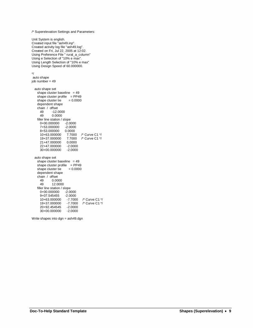
/* Superelevation Settings and Parameters:
Unit System is english. Created input file "ash49.inp". Created activity log file "ash49.log".
Created on Fri, Jul 22, 2005 at 12:02. Using Preference File " rural_a_column" Using e Selection of "10% e max".
Using Length Selection of "10% e max" Using Design Speed of 60.000000.
*/ auto shape job number = 49
auto shape set shape cluster baseline = 49
shape cluster profile = PP49 shape cluster tie = 0.0000 dependent shape
chain / offset 49 -12.0000 49 0.0000
filler line station / slope 0+00.000000 -2.0000 7+53.000000 -2.0000
8+53.000000 0.0000 10+63.000000 7.7000 /* Curve C1 */ 19+37.000000 7.7000 /* Curve C1 */
21+47.000000 0.0000 22+47.000000 -2.0000 30+00.000000 -2.0000
auto shape set shape cluster baseline = 49
shape cluster profile = PP49 shape cluster tie = 0.0000 dependent shape
chain / offset 49 0.0000 49 12.0000
filler line station / slope 0+00.000000 -2.0000 9+07.545455 -2.0000
10+63.000000 -7.7000 /* Curve C1 */ 19+37.000000 -7.7000 /* Curve C1 */ 20+92.454545 -2.0000
30+00.000000 -2.0000 Write shapes into dgn = ash49.dgn
Doc-To-Help Standard Template Shapes (Superelevation) 10
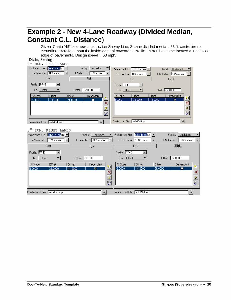
Example 2 - New 4-Lane Roadway (Divided Median, Constant C.L. Distance)
Given: Chain "49" is a new construction Survey Line, 2-Lane divided median, 88 ft. centerline to centerline. Rotation about the inside edge of pavement. Profile "PP49" has to be located at the inside edge of pavements. Design speed = 60 mph.
Dialog Settings 1ST RUN, LEFT LANES
2ND RUN, RIGHT LANES
Doc-To-Help Standard Template Shapes (Superelevation) 11
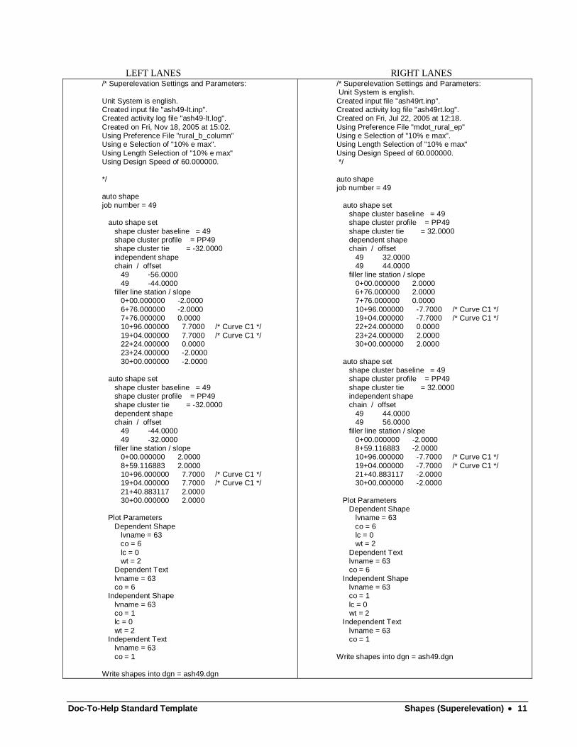
LEFT LANES RIGHT LANES
/* Superelevation Settings and Parameters:
Unit System is english. Created input file "ash49-lt.inp". Created activity log file "ash49-lt.log".
Created on Fri, Nov 18, 2005 at 15:02. Using Preference File "rural_b_column" Using e Selection of "10% e max".
Using Length Selection of "10% e max" Using Design Speed of 60.000000.
*/ auto shape
job number = 49 auto shape set
shape cluster baseline = 49 shape cluster profile = PP49 shape cluster tie = -32.0000
independent shape chain / offset 49 -56.0000
49 -44.0000 filler line station / slope 0+00.000000 -2.0000
6+76.000000 -2.0000 7+76.000000 0.0000 10+96.000000 7.7000 /* Curve C1 */
19+04.000000 7.7000 /* Curve C1 */ 22+24.000000 0.0000 23+24.000000 -2.0000
30+00.000000 -2.0000 auto shape set
shape cluster baseline = 49 shape cluster profile = PP49 shape cluster tie = -32.0000
dependent shape chain / offset 49 -44.0000
49 -32.0000 filler line station / slope 0+00.000000 2.0000
8+59.116883 2.0000 10+96.000000 7.7000 /* Curve C1 */ 19+04.000000 7.7000 /* Curve C1 */
21+40.883117 2.0000 30+00.000000 2.0000 Plot Parameters
Dependent Shape lvname = 63 co = 6
lc = 0 wt = 2 Dependent Text
lvname = 63 co = 6 Independent Shape
lvname = 63 co = 1 lc = 0
wt = 2 Independent Text lvname = 63
co = 1 Write shapes into dgn = ash49.dgn
/* Superelevation Settings and Parameters: Unit System is english.
Created input file "ash49rt.inp". Created activity log file "ash49rt.log". Created on Fri, Jul 22, 2005 at 12:18.
Using Preference File "mdot_rural_ep" Using e Selection of "10% e max". Using Length Selection of "10% e max"
Using Design Speed of 60.000000. */
auto shape job number = 49
auto shape set shape cluster baseline = 49 shape cluster profile = PP49
shape cluster tie = 32.0000 dependent shape chain / offset
49 32.0000 49 44.0000 filler line station / slope
0+00.000000 2.0000 6+76.000000 2.0000 7+76.000000 0.0000
10+96.000000 -7.7000 /* Curve C1 */ 19+04.000000 -7.7000 /* Curve C1 */ 22+24.000000 0.0000
23+24.000000 2.0000 30+00.000000 2.0000
auto shape set shape cluster baseline = 49 shape cluster profile = PP49
shape cluster tie = 32.0000 independent shape chain / offset
49 44.0000 49 56.0000 filler line station / slope
0+00.000000 -2.0000 8+59.116883 -2.0000 10+96.000000 -7.7000 /* Curve C1 */
19+04.000000 -7.7000 /* Curve C1 */ 21+40.883117 -2.0000 30+00.000000 -2.0000
Plot Parameters Dependent Shape lvname = 63
co = 6 lc = 0 wt = 2
Dependent Text lvname = 63 co = 6
Independent Shape lvname = 63 co = 1
lc = 0 wt = 2 Independent Text
lvname = 63 co = 1
Write shapes into dgn = ash49.dgn
Doc-To-Help Standard Template Shapes (Superelevation) 12
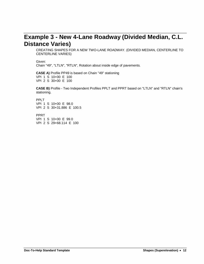
Example 3 - New 4-Lane Roadway (Divided Median, C.L. Distance Varies)
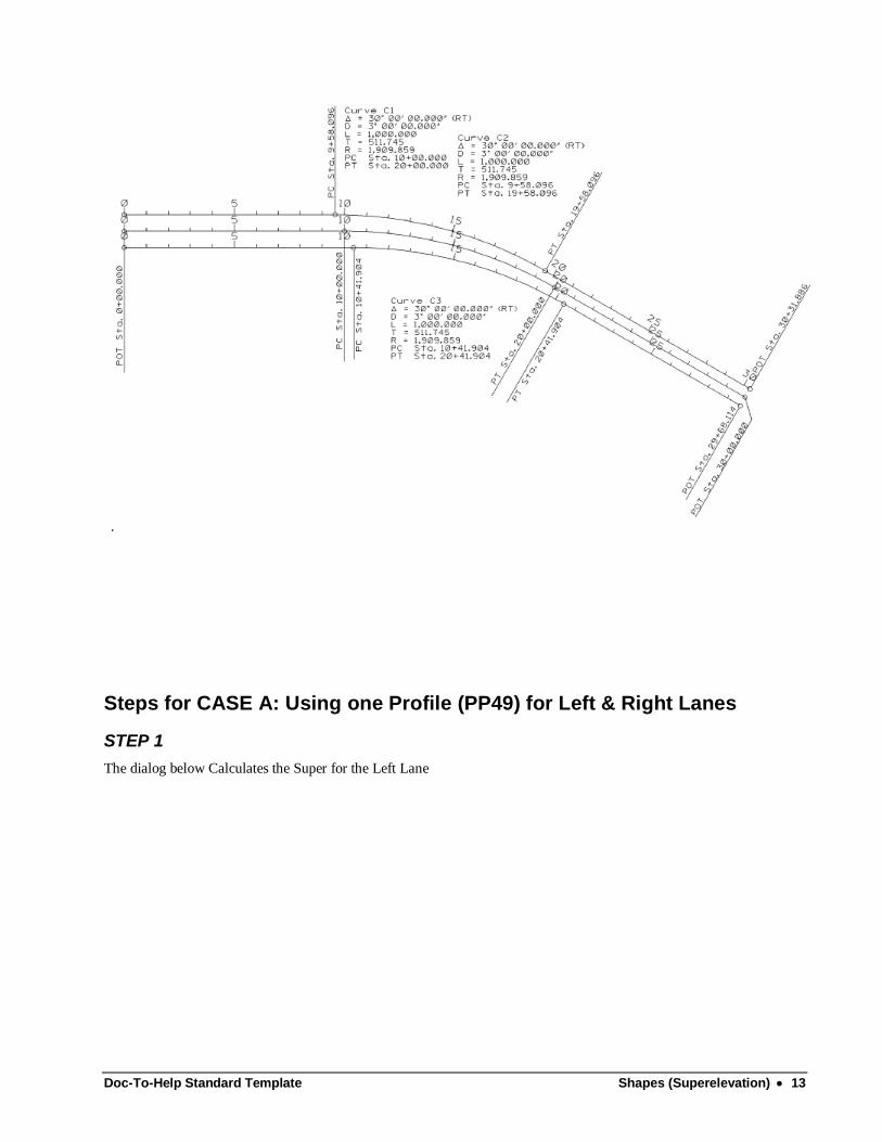
CREATING SHAPES FOR A NEW TWO-LANE ROADWAY. (DIVIDED MEDIAN, CENTERLINE TO CENTERLINE VARIES) Given: Chain "49", "LTLN", "RTLN", Rotation about inside edge of pavements. CASE A) Profile PP49 is based on Chain "49" stationing VPI 1 S 10+00 E 100 VPI 2 S 30+00 E 100 CASE B) Profile - Two Independent Profiles PPLT and PPRT based on "LTLN" and "RTLN" chain's stationing. PPLT VPI 1 S 10+00 E 98.0 VPI 2 S 30+31.886 E 100.5 PPRT VPI 1 S 10+00 E 99.0 VPI 2 S 29+68.114 E 100
Doc-To-Help Standard Template Shapes (Superelevation) 13
.
Steps for CASE A: Using one Profile (PP49) for Left & Right Lanes
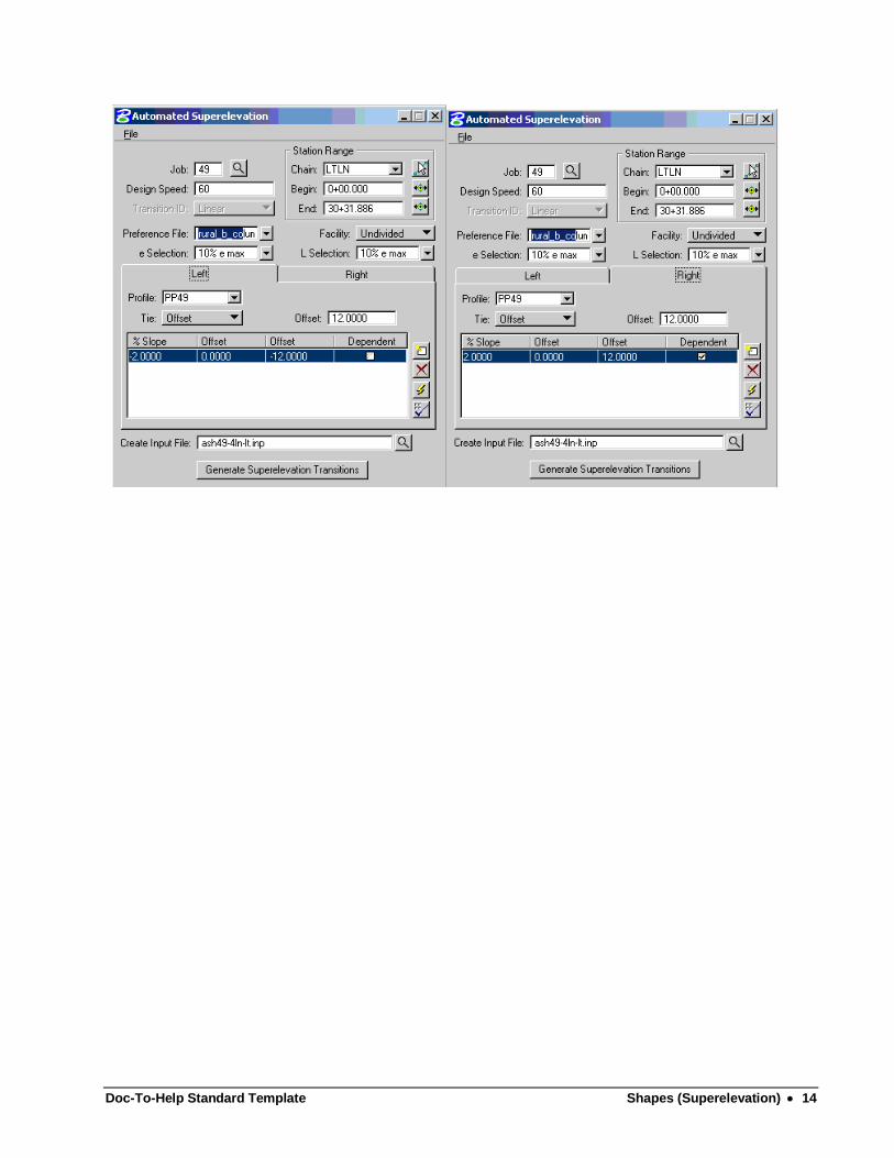
STEP 1
The dialog below Calculates the Super for the Left Lane
Doc-To-Help Standard Template Shapes (Superelevation) 14
Doc-To-Help Standard Template Shapes (Superelevation) 15
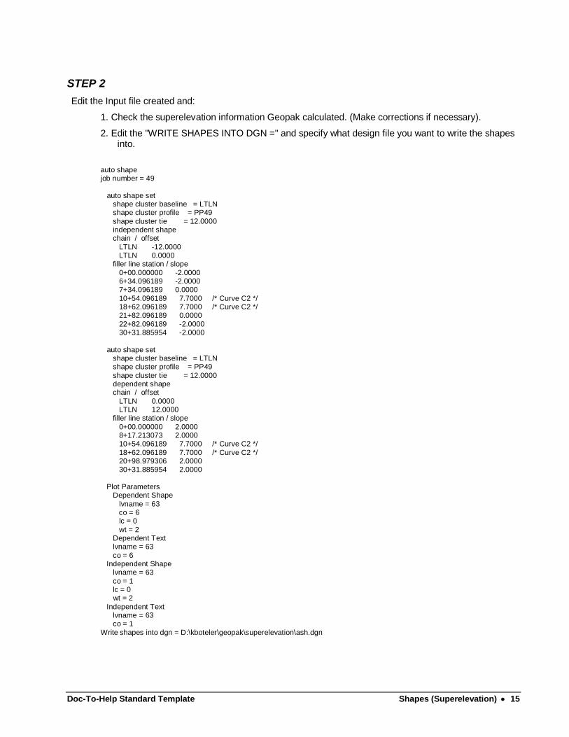
STEP 2
Edit the Input file created and:
1. Check the superelevation information Geopak calculated. (Make corrections if necessary).
2. Edit the "WRITE SHAPES INTO DGN =" and specify what design file you want to write the shapes into.
auto shape job number = 49
auto shape set shape cluster baseline = LTLN shape cluster profile = PP49
shape cluster tie = 12.0000 independent shape chain / offset
LTLN -12.0000 LTLN 0.0000 filler line station / slope
0+00.000000 -2.0000 6+34.096189 -2.0000 7+34.096189 0.0000
10+54.096189 7.7000 /* Curve C2 */ 18+62.096189 7.7000 /* Curve C2 */ 21+82.096189 0.0000
22+82.096189 -2.0000 30+31.885954 -2.0000
auto shape set shape cluster baseline = LTLN shape cluster profile = PP49
shape cluster tie = 12.0000 dependent shape chain / offset
LTLN 0.0000 LTLN 12.0000 filler line station / slope
0+00.000000 2.0000 8+17.213073 2.0000 10+54.096189 7.7000 /* Curve C2 */
18+62.096189 7.7000 /* Curve C2 */ 20+98.979306 2.0000 30+31.885954 2.0000
Plot Parameters Dependent Shape
lvname = 63 co = 6 lc = 0
wt = 2 Dependent Text lvname = 63
co = 6 Independent Shape lvname = 63
co = 1 lc = 0 wt = 2
Independent Text lvname = 63 co = 1
Write shapes into dgn = D:\kboteler\geopak\superelevation\ash.dgn
Doc-To-Help Standard Template Shapes (Superelevation) 16
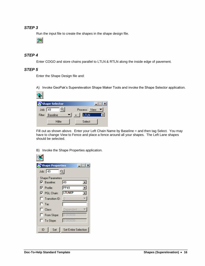
STEP 3
Run the input file to create the shapes in the shape design file.
STEP 4
Enter COGO and store chains parallel to LTLN & RTLN along the inside edge of pavement.
STEP 5
Enter the Shape Design file and:
A) Invoke GeoPak’s Superelevation Shape Maker Tools and invoke the Shape Selector application.
Fill out as shown above. Enter your Left Chain Name by Baseline = and then tag Select. You may have to change View to Fence and place a fence around all your shapes. The Left Lane shapes should be selected.
B) Invoke the Shape Properties application.
Doc-To-Help Standard Template Shapes (Superelevation) 17
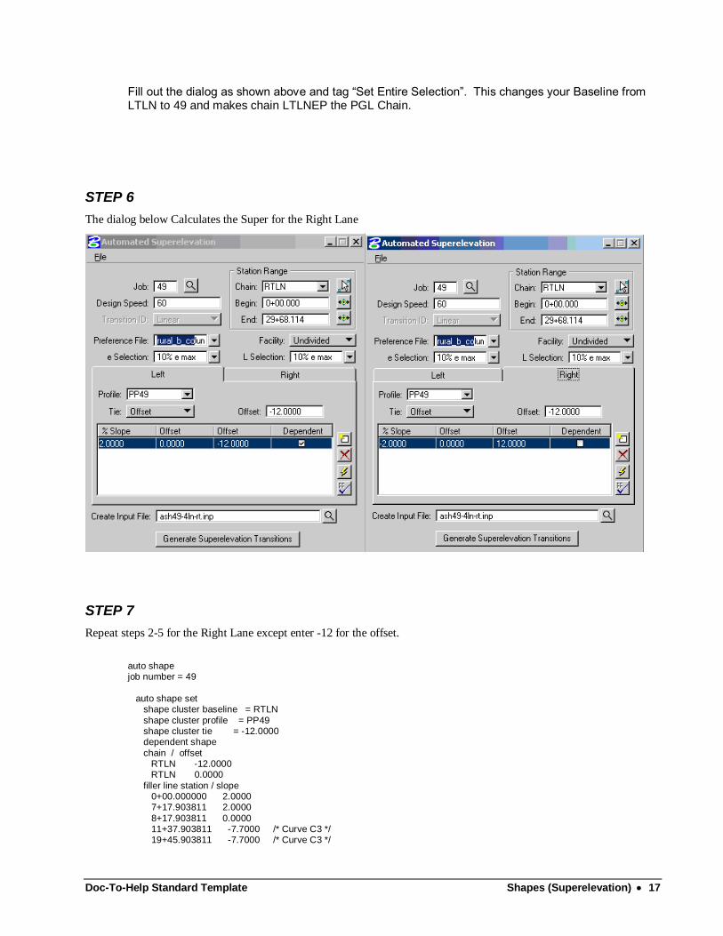
Fill out the dialog as shown above and tag “Set Entire Selection”. This changes your Baseline from LTLN to 49 and makes chain LTLNEP the PGL Chain.
STEP 6
The dialog below Calculates the Super for the Right Lane
STEP 7
Repeat steps 2-5 for the Right Lane except enter -12 for the offset.
auto shape job number = 49
auto shape set shape cluster baseline = RTLN
shape cluster profile = PP49 shape cluster tie = -12.0000 dependent shape
chain / offset RTLN -12.0000 RTLN 0.0000
filler line station / slope 0+00.000000 2.0000 7+17.903811 2.0000
8+17.903811 0.0000 11+37.903811 -7.7000 /* Curve C3 */ 19+45.903811 -7.7000 /* Curve C3 */

Doc-To-Help Standard Template Shapes (Superelevation) 18
22+65.903811 0.0000 29+68.114000 2.0000
auto shape set shape cluster baseline = RTLN
shape cluster profile = PP49 shape cluster tie = -12.0000 independent shape
chain / offset RTLN 0.0000 RTLN 12.0000
filler line station / slope 0+00.000000 -2.0000 9+01.020694 -2.0000
11+37.903811 -7.7000 /* Curve C3 */ 19+45.903811 -7.7000 /* Curve C3 */ 21+82.786927 -2.0000
29+68.114000 -2.0000 Plot Parameters
Dependent Shape lvname = 63 co = 6
lc = 0 wt = 2 Dependent Text
lvname = 63 co = 6 Independent Shape
lvname = 63 co = 1 lc = 0
wt = 2 Independent Text lvname = 63
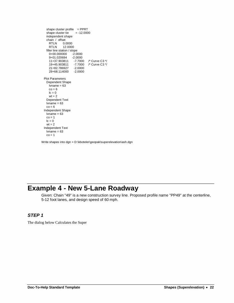
co = 1 Write shapes into dgn = D:\kboteler\geopak\superelevation\ash.dgn
Doc-To-Help Standard Template Shapes (Superelevation) 19
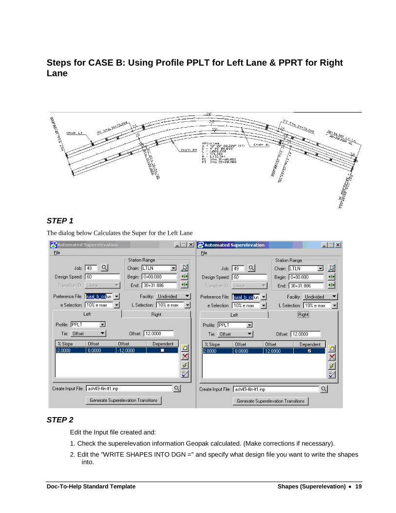
Steps for CASE B: Using Profile PPLT for Left Lane & PPRT for Right Lane
STEP 1
The dialog below Calculates the Super for the Left Lane
STEP 2
Edit the Input file created and:
1. Check the superelevation information Geopak calculated. (Make corrections if necessary).
2. Edit the "WRITE SHAPES INTO DGN =" and specify what design file you want to write the shapes into.
Doc-To-Help Standard Template Shapes (Superelevation) 20
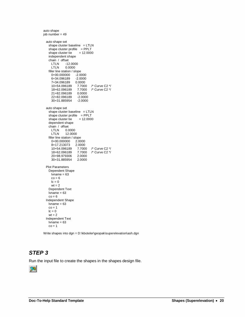
auto shape job number = 49
auto shape set shape cluster baseline = LTLN
shape cluster profile = PPLT shape cluster tie = 12.0000 independent shape
chain / offset LTLN -12.0000 LTLN 0.0000
filler line station / slope 0+00.000000 -2.0000 6+34.096189 -2.0000
7+34.096189 0.0000 10+54.096189 7.7000 /* Curve C2 */ 18+62.096189 7.7000 /* Curve C2 */
21+82.096189 0.0000 22+82.096189 -2.0000 30+31.885954 -2.0000
auto shape set shape cluster baseline = LTLN
shape cluster profile = PPLT shape cluster tie = 12.0000 dependent shape
chain / offset LTLN 0.0000 LTLN 12.0000
filler line station / slope 0+00.000000 2.0000 8+17.213073 2.0000
10+54.096189 7.7000 /* Curve C2 */ 18+62.096189 7.7000 /* Curve C2 */ 20+98.979306 2.0000
30+31.885954 2.0000 Plot Parameters
Dependent Shape lvname = 63 co = 6
lc = 0 wt = 2 Dependent Text
lvname = 63 co = 6 Independent Shape
lvname = 63 co = 1 lc = 0
wt = 2 Independent Text lvname = 63 co = 1
Write shapes into dgn = D:\kboteler\geopak\superelevation\ash.dgn
STEP 3
Run the input file to create the shapes in the shapes design file.
Doc-To-Help Standard Template Shapes (Superelevation) 21
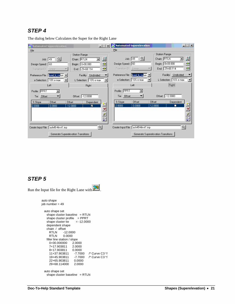
STEP 4
The dialog below Calculates the Super for the Right Lane
STEP 5
Run the Input file for the Right Lane with .
auto shape
job number = 49 auto shape set
shape cluster baseline = RTLN shape cluster profile = PPRT shape cluster tie = -12.0000
dependent shape chain / offset RTLN -12.0000
RTLN 0.0000 filler line station / slope 0+00.000000 2.0000
7+17.903811 2.0000 8+17.903811 0.0000 11+37.903811 -7.7000 /* Curve C3 */
19+45.903811 -7.7000 /* Curve C3 */ 22+65.903811 0.0000 29+68.114000 2.0000
auto shape set shape cluster baseline = RTLN
Doc-To-Help Standard Template Shapes (Superelevation) 22
shape cluster profile = PPRT shape cluster tie = -12.0000
independent shape chain / offset RTLN 0.0000
RTLN 12.0000 filler line station / slope 0+00.000000 -2.0000
9+01.020694 -2.0000 11+37.903811 -7.7000 /* Curve C3 */ 19+45.903811 -7.7000 /* Curve C3 */
21+82.786927 -2.0000 29+68.114000 -2.0000
Plot Parameters Dependent Shape lvname = 63
co = 6 lc = 0 wt = 2
Dependent Text lvname = 63 co = 6
Independent Shape lvname = 63 co = 1
lc = 0 wt = 2 Independent Text
lvname = 63 co = 1
Write shapes into dgn = D:\kboteler\geopak\superelevation\ash.dgn
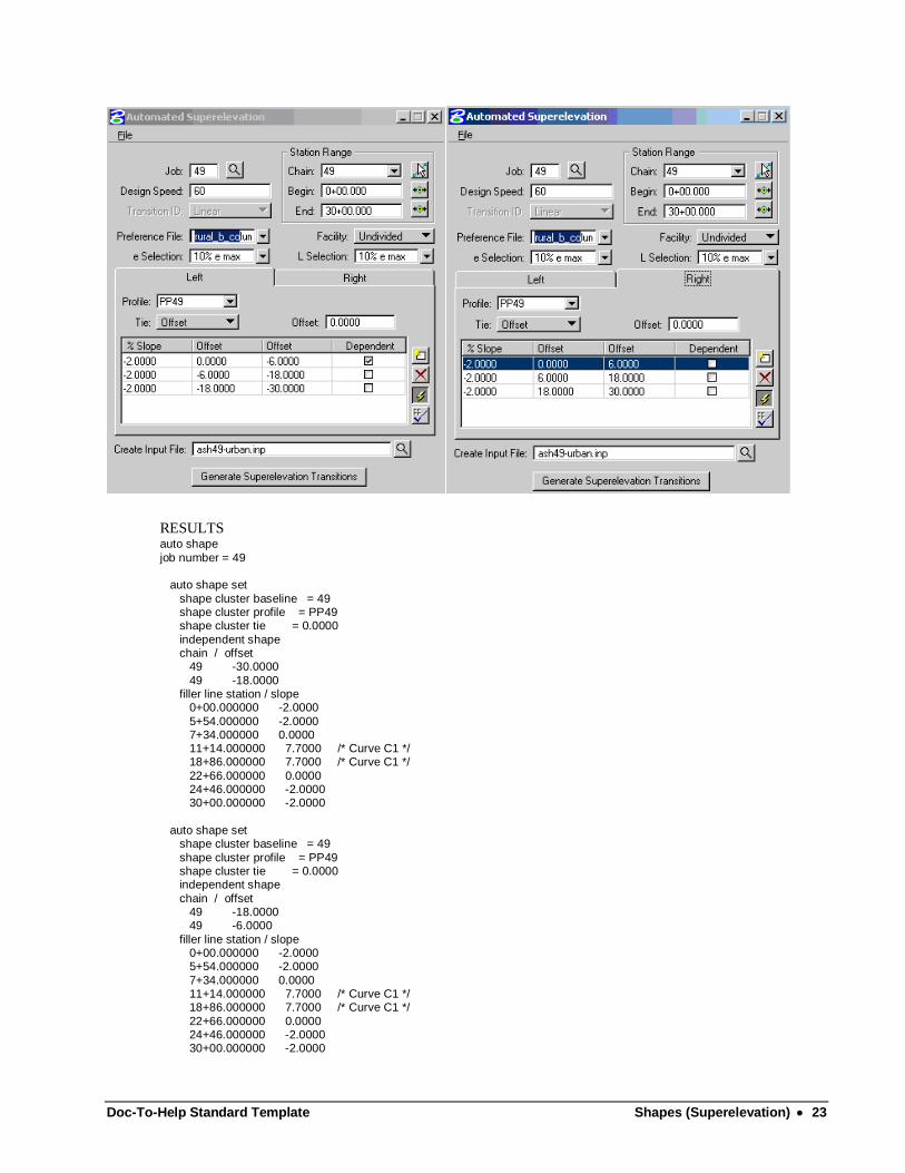
Example 4 - New 5-Lane Roadway Given: Chain "49" is a new construction survey line. Proposed profile name "PP49" at the centerline, 5-12 foot lanes, and design speed of 60 mph.
STEP 1
The dialog below Calculates the Super
Doc-To-Help Standard Template Shapes (Superelevation) 23
RESULTS auto shape
job number = 49 auto shape set
shape cluster baseline = 49 shape cluster profile = PP49 shape cluster tie = 0.0000
independent shape chain / offset 49 -30.0000
49 -18.0000 filler line station / slope 0+00.000000 -2.0000
5+54.000000 -2.0000 7+34.000000 0.0000 11+14.000000 7.7000 /* Curve C1 */ 18+86.000000 7.7000 /* Curve C1 */
22+66.000000 0.0000 24+46.000000 -2.0000 30+00.000000 -2.0000
auto shape set shape cluster baseline = 49
shape cluster profile = PP49 shape cluster tie = 0.0000 independent shape
chain / offset 49 -18.0000 49 -6.0000
filler line station / slope 0+00.000000 -2.0000 5+54.000000 -2.0000
7+34.000000 0.0000 11+14.000000 7.7000 /* Curve C1 */ 18+86.000000 7.7000 /* Curve C1 */
22+66.000000 0.0000 24+46.000000 -2.0000 30+00.000000 -2.0000
Doc-To-Help Standard Template Shapes (Superelevation) 24
auto shape set
shape cluster baseline = 49 shape cluster profile = PP49 shape cluster tie = 0.0000
dependent shape chain / offset 49 -6.0000
49 0.0000 filler line station / slope 0+00.000000 -2.0000
5+54.000000 -2.0000 7+34.000000 0.0000 11+14.000000 7.7000 /* Curve C1 */
18+86.000000 7.7000 /* Curve C1 */ 22+66.000000 0.0000 24+46.000000 -2.0000
30+00.000000 -2.0000 auto shape set
shape cluster baseline = 49 shape cluster profile = PP49 shape cluster tie = 0.0000
independent shape chain / offset 49 0.0000
49 6.0000 filler line station / slope 0+00.000000 -2.0000
8+32.701299 -2.0000 11+14.000000 -7.7000 /* Curve C1 */ 18+86.000000 -7.7000 /* Curve C1 */
21+67.298701 -2.0000 30+00.000000 -2.0000
auto shape set shape cluster baseline = 49 shape cluster profile = PP49
shape cluster tie = 0.0000 independent shape chain / offset
49 6.0000 49 18.0000 filler line station / slope
0+00.000000 -2.0000 8+32.701299 -2.0000 11+14.000000 -7.7000 /* Curve C1 */
18+86.000000 -7.7000 /* Curve C1 */ 21+67.298701 -2.0000 30+00.000000 -2.0000
auto shape set shape cluster baseline = 49 shape cluster profile = PP49
shape cluster tie = 0.0000 independent shape chain / offset
49 18.0000 49 30.0000 filler line station / slope
0+00.000000 -2.0000 8+32.701299 -2.0000 11+14.000000 -7.7000 /* Curve C1 */
18+86.000000 -7.7000 /* Curve C1 */ 21+67.298701 -2.0000 30+00.000000 -2.0000
Plot Parameters Dependent Shape
lvname = 63
Doc-To-Help Standard Template Other Components 25
co = 6 lc = 0
wt = 2 Dependent Text lvname = 63
co = 6 Independent Shape lvname = 63
co = 1 lc = 0 wt = 2
Independent Text lvname = 63 co = 1
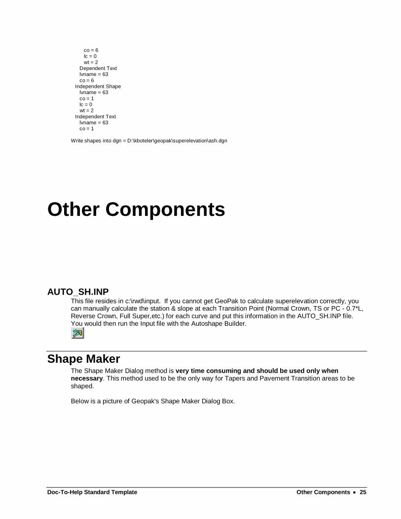
Write shapes into dgn = D:\kboteler\geopak\superelevation\ash.dgn
Other Components
AUTO_SH.INP This file resides in c:\rwd\input. If you cannot get GeoPak to calculate superelevation correctly, you can manually calculate the station & slope at each Transition Point (Normal Crown, TS or PC - 0.7*L, Reverse Crown, Full Super,etc.) for each curve and put this information in the AUTO_SH.INP file. You would then run the Input file with the Autoshape Builder.
Shape Maker The Shape Maker Dialog method is very time consuming and should be used only when necessary. This method used to be the only way for Tapers and Pavement Transition areas to be shaped. Below is a picture of Geopak's Shape Maker Dialog Box.
Doc-To-Help Standard Template Other Components 26
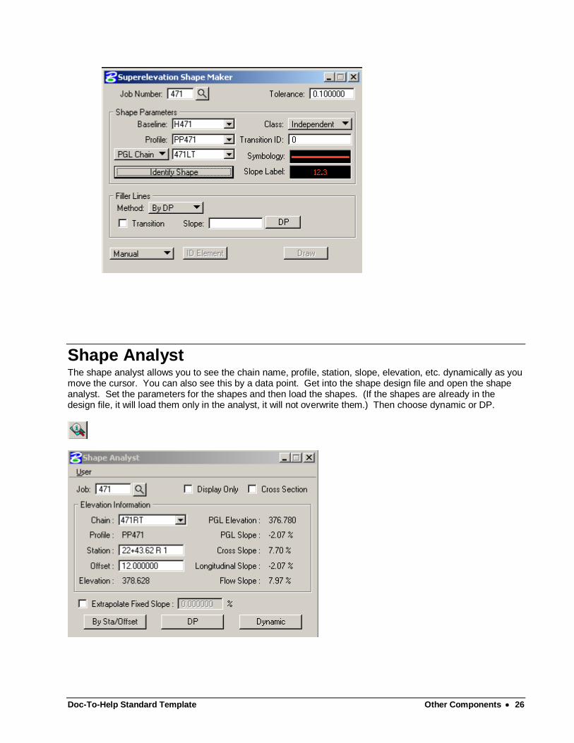
Shape Analyst The shape analyst allows you to see the chain name, profile, station, slope, elevation, etc. dynamically as you move the cursor. You can also see this by a data point. Get into the shape design file and open the shape analyst. Set the parameters for the shapes and then load the shapes. (If the shapes are already in the design file, it will load them only in the analyst, it will not overwrite them.) Then choose dynamic or DP.
Doc-To-Help Standard Template Other Components 27
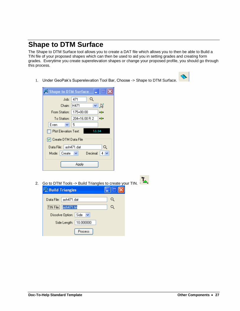
Shape to DTM Surface The Shape to DTM Surface tool allows you to create a DAT file which allows you to then be able to Build a TIN file of your proposed shapes which can then be used to aid you in setting grades and creating form grades. Everytime you create superelevation shapes or change your proposed profile, you should go through this process.
1. Under GeoPak’s Superelevation Tool Bar, Choose -> Shape to DTM Surface.
2. Go to DTM Tools -> Build Triangles to create your TIN.
Doc-To-Help Standard Template Other Components 28
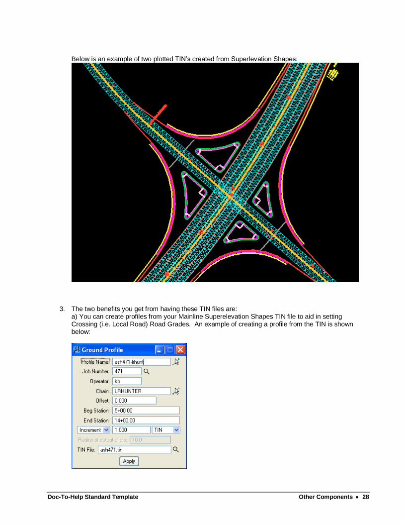
Below is an example of two plotted TIN’s created from Superlevation Shapes:
3. The two benefits you get from having these TIN files are: a) You can create profiles from your Mainline Superelevation Shapes TIN file to aid in setting Crossing (i.e. Local Road) Road Grades. An example of creating a profile from the TIN is shown below:
Doc-To-Help Standard Template Other Components 29
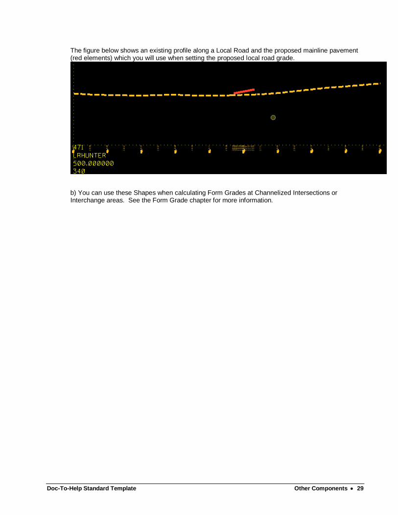
The figure below shows an existing profile along a Local Road and the proposed mainline pavement (red elements) which you will use when setting the proposed local road grade.
b) You can use these Shapes when calculating Form Grades at Channelized Intersections or Interchange areas. See the Form Grade chapter for more information.

Doc-To-Help Standard Template Glossary of Terms 30
Glossary of Terms

Doc-To-Help Standard Template Index 31
Index
Error! No index entries found.