YarwaY hardseat and seatless tandem blow-off valve service ... · bearing faces against the cutting...
4
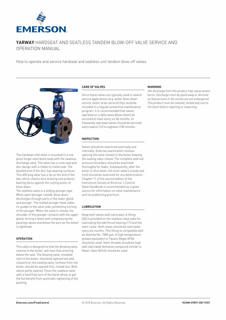
YARWAY HARDSEAT AND SEATLESS TANDEM BLOW-OFF VALVE SERVICE AND OPERATION MANUAL How to operate and service hardseat and seatless unit tandem blow-off valves The hardseat inlet valve is mounted in a one piece forget steel block body with the seatless discharge valve. The valve has a cone seat and disc design with a metal-to metal seat. The beveled end of the disc has wearing surfaces. This 600 psig valve has a lip on the end of the disc which checks wire drawing and protects bearing faces against the cutting action of blow-down. The seatless valve is a sliding-plunger type. When open (plunger raised), blow-down discharges through ports in the lower gland and plunger. The slotted plunger head slides on guides in the valve yoke, preventing turning of the plunger. When the valve is closed, the shoulder of the plunger contacts with the upper gland, forcing it down and compressing the packings above and below the port as the wheel is tightened. © 2018 Emerson. All Rights Reserved. Emerson.com/FinalControl VCIOM-07091-EN 19/01 OPERATION This valve is designed so that the blowing valve, nearest to the boiler, will have flow entering below the seat. The blowing valve, installed next to the boiler, should be opened last and closed first; the sealing valve, furthest from the boiler, should be opened first, closed last. Both valves partly opened. Close the seatless valve with a hard final turn of the hand-wheel to get the full benefit from automatic tightening of the packing. CARE OF VALVES Since these valves are typically used in severe service applications (e.g. boiler blow-down service, boiler drain service) they sould be included in a regular preventive maintenance program. It is recommended that valves operated on a daily basis (blow-down) be serviced at least every six (6) months. In frequently operated valves should be serviced every twelve (12) to eighteen (18) months. INSPECTION Valves should be examined externally and internally. External examination involves opening the valve closest to the boiler keeping the sealing valve closed. The complete external pressure boundary should be examined thoroughly for leaks. Subsequently, after the boiler is shut down, the inner valve (i.e.body and trim) should be examined for any deterioration. Chapter 11 of the second edition of the Instrument Society of America´s Control Valve Handbook is recommended as a good source for information on valve maintenance and reconditioning practices. LUBRICATION Keep both valves well lubricated. A fitting (2A) is provided on the seatless valve yoke for lubricating the ball thrust bearing (11) and the stem collar. Both areas should be lubricated every six months. This fitting is compatible with an Alemite No. 7585 gun. A high temperature grease equivalent to Texaco Regal AFB2 should be used. Stem threads should be kept well lubricated Antiseize compound similar to Never-Seez NS165 should be used. WARNING Hot discharge from this product may cause severe burns. Discharge must be piped away or directed so that persons in the vicinity are not endangered. This product must be isolated, vented and cool to the touch before repairing or inspecting.
Transcript of YarwaY hardseat and seatless tandem blow-off valve service ... · bearing faces against the cutting...
YarwaY hardseat and seatless tandem blow-off valve service and operation manual
how to operate and service hardseat and seatless unit tandem blow-off valves
the hardseat inlet valve is mounted in a one piece forget steel block body with the seatless discharge valve. the valve has a cone seat and disc design with a metal-to metal seat. the beveled end of the disc has wearing surfaces.this 600 psig valve has a lip on the end of the disc which checks wire drawing and protects bearing faces against the cutting action of blow-down.the seatless valve is a sliding-plunger type. when open (plunger raised), blow-down discharges through ports in the lower gland and plunger. the slotted plunger head slides on guides in the valve yoke, preventing turning of the plunger. when the valve is closed, the shoulder of the plunger contacts with the upper gland, forcing it down and compressing the packings above and below the port as the wheel is tightened.
© 2018 emerson. all rights reserved.Emerson.com/FinalControl VCIOM-07091-EN 19/01
OPEraTION
this valve is designed so that the blowing valve, nearest to the boiler, will have flow entering below the seat. the blowing valve, installed next to the boiler, should be opened last and closed first; the sealing valve, furthest from the boiler, should be opened first, closed last. both valves partly opened. close the seatless valve with a hard final turn of the hand-wheel to get the full benefit from automatic tightening of the packing.
CarE OF VaLVES
since these valves are typically used in severe service applications (e.g. boiler blow-down service, boiler drain service) they sould be included in a regular preventive maintenance program. it is recommended that valves operated on a daily basis (blow-down) be serviced at least every six (6) months. in frequently operated valves should be serviced every twelve (12) to eighteen (18) months.
INSPECTION
valves should be examined externally and internally. external examination involves opening the valve closest to the boiler keeping the sealing valve closed. the complete external pressure boundary should be examined thoroughly for leaks. subsequently, after the boiler is shut down, the inner valve (i.e.body and trim) should be examined for any deterioration. chapter 11 of the second edition of the instrument society of america´s control valve handbook is recommended as a good source for information on valve maintenance and reconditioning practices.
LUBrICaTION
Keep both valves well lubricated. a fitting (2a) is provided on the seatless valve yoke for lubricating the ball thrust bearing (11) and the stem collar. both areas should be lubricated every six months. this fitting is compatible with an alemite no. 7585 gun. a high temperature grease equivalent to texaco regal afb2 should be used. stem threads should be kept well lubricated antiseize compound similar to never-seez ns165 should be used.
warNINGHot discharge from this product may cause severe burns. Discharge must be piped away or directed so that persons in the vicinity are not endangered. This product must be isolated, vented and cool to the touch before repairing or inspecting.

2
YarwaY hardseat and seatless tandem blow-off valve service and operation manual
hardSEaT VaLVE
for cleaning, all internal parts of the hardseat valve may be removed without disconnecting the body from the line. if the inside of the valve must be cleaned, or if a foreign body lodged in the valve prevents proper seating of the disc, disassemble as follows: (1) loosen the gland flange and remove the split gland bushing(2) turn the handwheel past its full open position to jack the packing and stuffing box(3) break the tack weld on the yoke bushing and back out this bushing (4) remove the internal parts through the top of the yoke. when the valve is reassembled, the yoke must be tack welded in place to prevent accidental loosening of the bushing while the valve is in service. it is also advisable to keep the disc clear of the seat during reassembly of the yoke bushing.
SEaTLESS VaLVEItem description1 body assembly2 Yoke2a lubrication fitting3 lower packing ring assembly4 upper packing ring assembly5 lower gland6 upper gland8 plunger assembly9 stem11 ball thrust bearing12 handwheel13 stop screw13a stop screw gasket14 springs15 Yoke studs15a Yoke stud nuts (4 per set)
hardSEaT SEaT VaLVEItem description1 body assembly19 Gland20 disc21 split gland bushing22 disc nut23 stuffing box bushing24 Yoke bushing25 stem26 Gland bolts27 handwheel28 packing31 disc insert
SEaTLESS VaLVE
packing ring adjustment yoke nuts (15a) should be tightened at regular intervals. the yoke springs (14) will maintain a constant load on the packing, but the packing rings will relax slightly during use and an adjustment may be required. to adjust the packing, back the plunger off slightly by turning the handwheel (do not allow flow to occur) and then tighten the yoke nuts. ¼ to ½ turn should be sufficient. reseat the plunger against the upper gland.
NOTE: if the valve has not been operated for a long period, the packing nuts should be ajusted prior to blowing down the boiler.
reseating hardseat valvea specially designed Yarway reseating tool cuts a new surface on a worn or damaged seat without removing the unit-tandem valve from the line. there are cutters of various sizes to assure that all seats are cut at the proper angle without lapping the seat and disc. prices and complete details are available.
seatless valve
Hardseat valve

3
� ���
�� �
�
YarwaY hardseat and seatless tandem blow-off valve service and operation manual
INSTaLLaTION OF PaCkING rINGS
warNINGThis procedure should not be attempted unless all pressure has been vented from the valve and its connecting lines, and the temperature of the valve is at or near ambient.Remove the stopscrew (13) yoke nuts and springs. Turn the hand-wheel to open the valve. This will raise the plunger. Turn the handwheel to close the valve. This will raise the yoke. Turn the yoke so that the holes and studs are out of line and turn the handwheel to open the valve. The plunger is thus withdrawn from the valve.Next, remove the glands and the old packing. This can be done by using a Yarway gland and packing puller or similar tool (Fig. 3) in the following manner: Insert the tool until the pawls engage the ports in the lower gland. Tighten the nut on the top of the puller to draw out the lower gland, upper packing and upper gland. The lower packing can then be removed using a hook tool. Care should be exercised, however, so that the lower packing groove is not damage. Install new packing rings (Fig. 4 or 5) glands and stopscrew in the body and replace the yoke, with the plunger screwed all the way up on the stem, using the yoke nuts to pull down the yoke assembly. Next, place the springs under the nuts and adjust as previously described.
hardSEaT SEaT VaLVEITEM dESCrIPTION1 bridge plate assembly2 Jack screw3 spring4 thrust washer5 nut 1¼ hex6 screw (spring mtg.)
SEaTLESS VaLVE GLaNd aNd PaCkING PULLEr
ITEM dESCrIPTION946458 packing puller w/box* 946459-01 1, 1¼ head assembly946459-02 1½ head assembly946459-03 2 head assembly 946459-04 2½ head assembly
NOTE:* use for all size seatless bo valves. in addition order appropriate size head assembly
fiGure 3seatless blow-off valve and gland packing puller assembly
fiGure 5with support ring
fiGure 4without support ring
upper gland
upper packing backup ring
upper packing ring
valve inlet
plunger
lower gland
support ring
lower packing ring
upper gland
upper packing backup ring
upper packing ring
valve inlet
plunger
valve body
upper gland
lower gland
a
a
upper packing
lower packing
lower gland
lower packing ring
note: chisel marks on head give indication of direction of pawls when inside valve body
edge of hole peened to hold pin in place
head assembly interchange head assembly available for either 1”, 1¼”, 1½”, 2” or 2½”valves. order size or sizes required.head assembly fits all types of Yarway seatless valves in size specified
4
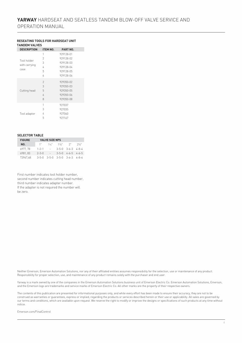
6977, 78 1-2-1 - 3-5-0 3-6-3 4-8-46981, 83 2-3-0 - 3-5-0 4-6-5 4-6-5t3947,48 3-5-0 3-5-0 3-5-0 3-6-3 4-8-4
rESEaTING TOOLS FOr hardSEaT UNIT TaNdEM VaLVES
dESCrIPTION ITEM NO. ParT NO.
tool holder with carrying case
123456
929128-01929128-02929128-03929128-04929128-05929128-06
cutting head
23568
929350-02929350-03929350-05929350-06929350-08
tool adapter
1345
927037927035927040927167
SELECTOr TaBLEFIGUrE NO.
VaLVE SIZE NPS1" 1¼" 1½" 2" 2½"
first number indicates tool holder number, second number indicates cutting head number, third number indicates adapter number.if the adapter is not required the number will be zero.
YarwaY hardseat and seatless tandem blow-off valve service and operation manual
neither emerson, emerson automation solutions, nor any of their affiliated entities assumes responsibility for the selection, use or maintenance of any product. responsibility for proper selection, use, and maintenance of any product remains solely with the purchaser and end user. Yarway is a mark owned by one of the companies in the emerson automation solutions business unit of emerson electric co. emerson automation solutions, emerson, and the emerson logo are trademarks and service marks of emerson electric co. all other marks are the property of their respective owners. the contents of this publication are presented for informational purposes only, and while every effort has been made to ensure their accuracy, they are not to be construed as warranties or guarantees, express or implied, regarding the products or services described herein or their use or applicability. all sales are governed by our terms and conditions, which are available upon request. we reserve the right to modify or improve the designs or specifications of such products at any time without notice. emerson.com/finalcontrol