plunger fall velocity considerations - T-Ram Canada...
14
PLUNGER FALL VELOCITY CONSIDERATIONS O. Lynn Rowlan, James N. McCoy, Echometer Company. J F Lea, Pltech LLC, Rick Nadkrynechny, T-RAM Canada Inc. Abstract Data acquired at various wells will be used to correlate the construction features of different types of plungers with their fall velocity. Some construction features cause a plunger to fall rapidly, while other features cause the plunger to have a slower fall velocity. Well conditions (gas flow rate and pressure) have a significant impact on plunger fall velocity. Published fall velocities can be used for each plunger type but may not be accurate for all wells, because fall velocity is impacted by many parameters. By accurately measuring the plunger fall velocity, the proper shut-in time for the plunger lift installation can be determined. The knowledge of how various parameters impact plunger fall velocity allows the operator to ensure that the plunger has reached the bottom of the tubing by the end of the shut-in period. Setting the well’s control ler to have the shortest possible shut-in time can maximize oil and gas production from the plunger lift well. Introduction Plunger lift is a low cost method for lifting liquids (water, condensate and/or oil) from gas and oil wells. This system reduces the cost of operating a well compared to other artificial lift methods, because stored formation pressure supplies the energy used to lift the liquids. During plunger lift operations flow from the well is controlled by repeated cycles of valve open with surface gas flow followed by valve closed with surface gas flow shut-in. During shut-in the gas flow down the flowline is stopped when the surface controller closes the motor valve. Closing the valve and associated pressure increase or catcher release allows the plunger to begin falling down the tubing. After plunger control parameters are met then the surface flow valve opens and the tubing gas flows into the low-pressure of the flowline. High pressure gas in the tubing above the liquid column flows down the flow line and the high pressure gas in the casing begins to drop to a lower pressures expanding to fill the tubing and displace the plunger and most of the liquid above the plunger to the surface. During this process the bottomhole pressure is reduced to allow additional gas to flow from the formation and casing annulus and be produced to the surface. This plunger operation cycle is continually repeated to produce the well. An operator can produce the well more efficiently if the plunger fall rate, plunger location, and time the plunger takes to fall to the liquid and bottom of tubing are determined. The distance to the plunger and the rate of fall can be measured when the plunger is in the gas above the liquid. When the plunger falls into the gaseous liquid column at the bottom of the tubing and the tubing pressure is high, then the acoustic and pressure signals the plunger creates as plunger travels past a tubing collar recesses can often be detected at the surface and fall velocity through the gaseous liquid column can also be accurately determined. The Shut-in period begins when the surface valves close, the well is shut-in and the plunger falls down the tubing. The plunger falls through gas until it hits the accumulated liquid at the bottom of the tubing. The plunger then falls through at least some of the accumulated liquid at the bottom of the tubing. Ideally the plunger falls to the bottom of the tubing and rests on the bumper spring. During the shut-in period casing pressure should build high enough to lift the accumulated fluids and the plunger to the surface. Fig. 1 is a plot of the casing pressure, tubing pressure and acoustic data acquired during one complete cycle of a typical plunger lift system. The key events that occurred during the cycle are annotated on Fig. 1. Table 1 list the casing pressure, tubing pressure and the time of each key event occurring during the 11.4 minute Unloading, the 22.1 minute Afterflow and the 67 minute Shut-in time periods of a cycle. For this cycle the dual padded plunger fell through 7309 feet of gas at an average fall velocity of 168.3 feet per minute and fell through 434 feet of gassy fluid at an average fall velocity of 38.9 feet per minute, reaching bottom in 57.0 minutes of elapsed time. The plot shows only one complete cycle of data. The plunger was resting on bottom for 10 minutes and increased gas flow from the well is possible if the Shut-in time is reduced by up to 10 minutes. The plunger lift operation cycle had a time period of 100.5 minutes and repeated at a frequency of 14.3 cycles per day, which was sufficient to remove the liquids that accumulate at the bottom of the tubing thus keeping the gas flowing at the desired rate. When using a digital fluid level instrument the sensitivity of the system is such that the gas gun microphone can be used to detect plunger location during the plunger fall by monitoring and digitally recording the acoustic signal at the surface of the tubing as a function of time. The plunger provides a type of seal between the plunger and the
-
Upload
trinhtuyen -
Category
Documents
-
view
216 -
download
2
Transcript of plunger fall velocity considerations - T-Ram Canada...

PLUNGER FALL VELOCITY CONSIDERATIONS O. Lynn Rowlan, James N. McCoy, Echometer Company.
J F Lea, Pltech LLC,
Rick Nadkrynechny, T-RAM Canada Inc.
Abstract
Data acquired at various wells will be used to correlate the construction features of different types of plungers with
their fall velocity. Some construction features cause a plunger to fall rapidly, while other features cause the plunger
to have a slower fall velocity. Well conditions (gas flow rate and pressure) have a significant impact on plunger fall
velocity. Published fall velocities can be used for each plunger type but may not be accurate for all wells, because
fall velocity is impacted by many parameters.
By accurately measuring the plunger fall velocity, the proper shut-in time for the plunger lift installation can be
determined. The knowledge of how various parameters impact plunger fall velocity allows the operator to ensure
that the plunger has reached the bottom of the tubing by the end of the shut-in period. Setting the well’s controller
to have the shortest possible shut-in time can maximize oil and gas production from the plunger lift well.
Introduction Plunger lift is a low cost method for lifting liquids (water, condensate and/or oil) from gas and oil wells. This
system reduces the cost of operating a well compared to other artificial lift methods, because stored formation
pressure supplies the energy used to lift the liquids. During plunger lift operations flow from the well is controlled
by repeated cycles of valve open with surface gas flow followed by valve closed with surface gas flow shut-in.
During shut-in the gas flow down the flowline is stopped when the surface controller closes the motor valve.
Closing the valve and associated pressure increase or catcher release allows the plunger to begin falling down the tubing. After plunger control parameters are met then the surface flow valve opens and the tubing gas flows into the
low-pressure of the flowline. High pressure gas in the tubing above the liquid column flows down the flow line and
the high pressure gas in the casing begins to drop to a lower pressures expanding to fill the tubing and displace the
plunger and most of the liquid above the plunger to the surface. During this process the bottomhole pressure is
reduced to allow additional gas to flow from the formation and casing annulus and be produced to the surface. This
plunger operation cycle is continually repeated to produce the well.
An operator can produce the well more efficiently if the plunger fall rate, plunger location, and time the plunger
takes to fall to the liquid and bottom of tubing are determined. The distance to the plunger and the rate of fall can be
measured when the plunger is in the gas above the liquid. When the plunger falls into the gaseous liquid column at
the bottom of the tubing and the tubing pressure is high, then the acoustic and pressure signals the plunger creates as
plunger travels past a tubing collar recesses can often be detected at the surface and fall velocity through the gaseous liquid column can also be accurately determined. The Shut-in period begins when the surface valves close, the well
is shut-in and the plunger falls down the tubing. The plunger falls through gas until it hits the accumulated liquid at
the bottom of the tubing. The plunger then falls through at least some of the accumulated liquid at the bottom of the
tubing. Ideally the plunger falls to the bottom of the tubing and rests on the bumper spring. During the shut-in
period casing pressure should build high enough to lift the accumulated fluids and the plunger to the surface.
Fig. 1 is a plot of the casing pressure, tubing pressure and acoustic data acquired during one complete cycle of a
typical plunger lift system. The key events that occurred during the cycle are annotated on Fig. 1. Table 1 list the
casing pressure, tubing pressure and the time of each key event occurring during the 11.4 minute Unloading, the
22.1 minute Afterflow and the 67 minute Shut-in time periods of a cycle. For this cycle the dual padded plunger
fell through 7309 feet of gas at an average fall velocity of 168.3 feet per minute and fell through 434 feet of gassy fluid at an average fall velocity of 38.9 feet per minute, reaching bottom in 57.0 minutes of elapsed time. The plot
shows only one complete cycle of data. The plunger was resting on bottom for 10 minutes and increased gas flow
from the well is possible if the Shut-in time is reduced by up to 10 minutes. The plunger lift operation cycle had a
time period of 100.5 minutes and repeated at a frequency of 14.3 cycles per day, which was sufficient to remove the
liquids that accumulate at the bottom of the tubing thus keeping the gas flowing at the desired rate.
When using a digital fluid level instrument the sensitivity of the system is such that the gas gun microphone can be
used to detect plunger location during the plunger fall by monitoring and digitally recording the acoustic signal at
the surface of the tubing as a function of time. The plunger provides a type of seal between the plunger and the
2
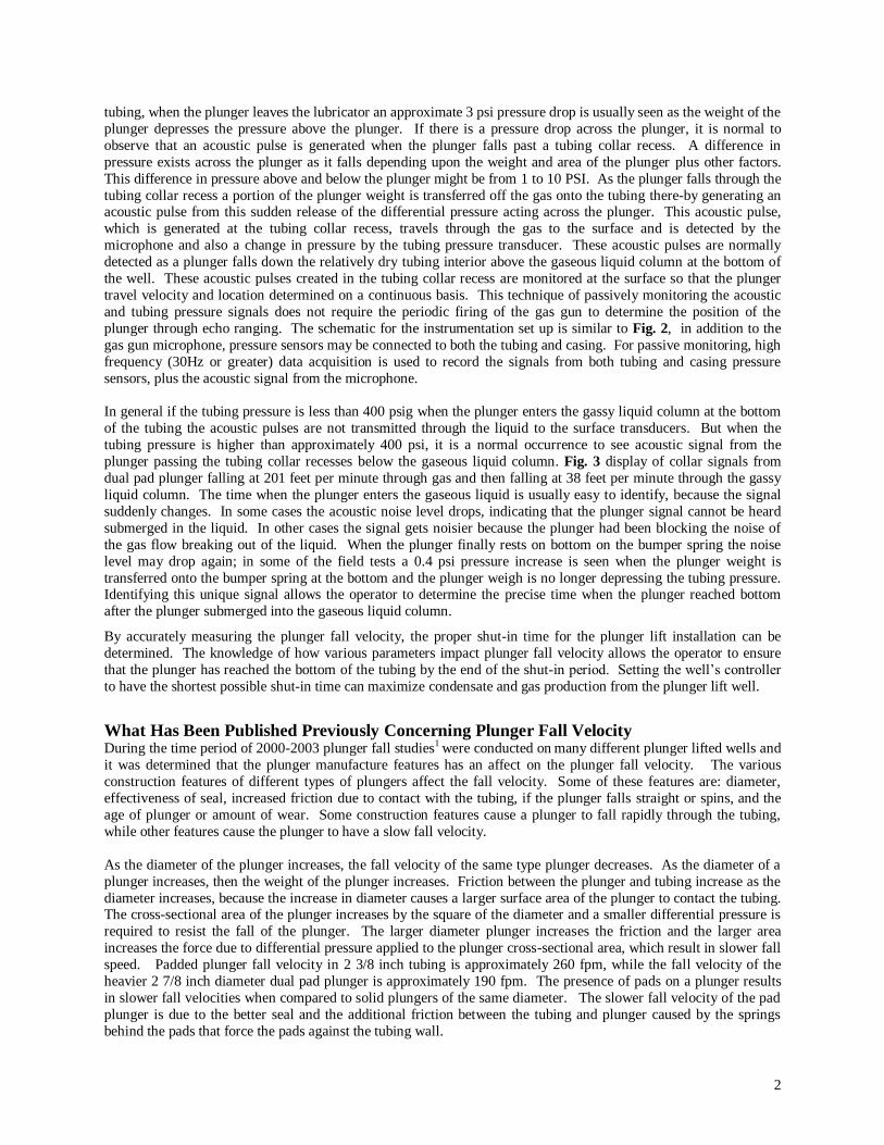
tubing, when the plunger leaves the lubricator an approximate 3 psi pressure drop is usually seen as the weight of the
plunger depresses the pressure above the plunger. If there is a pressure drop across the plunger, it is normal to
observe that an acoustic pulse is generated when the plunger falls past a tubing collar recess. A difference in
pressure exists across the plunger as it falls depending upon the weight and area of the plunger plus other factors.
This difference in pressure above and below the plunger might be from 1 to 10 PSI. As the plunger falls through the
tubing collar recess a portion of the plunger weight is transferred off the gas onto the tubing there-by generating an acoustic pulse from this sudden release of the differential pressure acting across the plunger. This acoustic pulse,
which is generated at the tubing collar recess, travels through the gas to the surface and is detected by the
microphone and also a change in pressure by the tubing pressure transducer. These acoustic pulses are normally
detected as a plunger falls down the relatively dry tubing interior above the gaseous liquid column at the bottom of
the well. These acoustic pulses created in the tubing collar recess are monitored at the surface so that the plunger
travel velocity and location determined on a continuous basis. This technique of passively monitoring the acoustic
and tubing pressure signals does not require the periodic firing of the gas gun to determine the position of the
plunger through echo ranging. The schematic for the instrumentation set up is similar to Fig. 2, in addition to the
gas gun microphone, pressure sensors may be connected to both the tubing and casing. For passive monitoring, high
frequency (30Hz or greater) data acquisition is used to record the signals from both tubing and casing pressure
sensors, plus the acoustic signal from the microphone.
In general if the tubing pressure is less than 400 psig when the plunger enters the gassy liquid column at the bottom
of the tubing the acoustic pulses are not transmitted through the liquid to the surface transducers. But when the
tubing pressure is higher than approximately 400 psi, it is a normal occurrence to see acoustic signal from the
plunger passing the tubing collar recesses below the gaseous liquid column. Fig. 3 display of collar signals from
dual pad plunger falling at 201 feet per minute through gas and then falling at 38 feet per minute through the gassy
liquid column. The time when the plunger enters the gaseous liquid is usually easy to identify, because the signal
suddenly changes. In some cases the acoustic noise level drops, indicating that the plunger signal cannot be heard
submerged in the liquid. In other cases the signal gets noisier because the plunger had been blocking the noise of
the gas flow breaking out of the liquid. When the plunger finally rests on bottom on the bumper spring the noise
level may drop again; in some of the field tests a 0.4 psi pressure increase is seen when the plunger weight is
transferred onto the bumper spring at the bottom and the plunger weigh is no longer depressing the tubing pressure. Identifying this unique signal allows the operator to determine the precise time when the plunger reached bottom
after the plunger submerged into the gaseous liquid column.
By accurately measuring the plunger fall velocity, the proper shut-in time for the plunger lift installation can be
determined. The knowledge of how various parameters impact plunger fall velocity allows the operator to ensure
that the plunger has reached the bottom of the tubing by the end of the shut-in period. Setting the well’s controller
to have the shortest possible shut-in time can maximize condensate and gas production from the plunger lift well.
What Has Been Published Previously Concerning Plunger Fall Velocity During the time period of 2000-2003 plunger fall studies1 were conducted on many different plunger lifted wells and
it was determined that the plunger manufacture features has an affect on the plunger fall velocity. The various
construction features of different types of plungers affect the fall velocity. Some of these features are: diameter,
effectiveness of seal, increased friction due to contact with the tubing, if the plunger falls straight or spins, and the
age of plunger or amount of wear. Some construction features cause a plunger to fall rapidly through the tubing,
while other features cause the plunger to have a slow fall velocity.
As the diameter of the plunger increases, the fall velocity of the same type plunger decreases. As the diameter of a
plunger increases, then the weight of the plunger increases. Friction between the plunger and tubing increase as the
diameter increases, because the increase in diameter causes a larger surface area of the plunger to contact the tubing. The cross-sectional area of the plunger increases by the square of the diameter and a smaller differential pressure is
required to resist the fall of the plunger. The larger diameter plunger increases the friction and the larger area
increases the force due to differential pressure applied to the plunger cross-sectional area, which result in slower fall
speed. Padded plunger fall velocity in 2 3/8 inch tubing is approximately 260 fpm, while the fall velocity of the
heavier 2 7/8 inch diameter dual pad plunger is approximately 190 fpm. The presence of pads on a plunger results
in slower fall velocities when compared to solid plungers of the same diameter. The slower fall velocity of the pad
plunger is due to the better seal and the additional friction between the tubing and plunger caused by the springs
behind the pads that force the pads against the tubing wall.

3
The effectiveness of the seal to prevent or allow fluids to flow past the plunger has a major impact on fall velocity.
Padded plungers have the best seal and have a slow fall velocity. If rubber or neoprene is placed between a set of
pads and the plunger body, then the improved seal results in a much slower plunger fall. This better seal feature
might be desired if liquid or gas slipping past the plunger is a problem. Rubber or neoprene provides a good seal to restrict gas from flowing past the plunger and results in a slowest fall velocity of 159 fpm in 2 3/8 inch tubing. The
by-pass type of plunger has a valve that opens to allow unrestricted gas glow through the plunger creating a large
opening through the plunger and this lack of seal allows fluids to flow easily through the plunger. The ability to by-
pass fluids through the plunger results in the highest fall velocity above 1000 fpm.
The brush plungers have the largest difference of fall velocity of any type of plunger. The fall velocity of the worn
brush plunger ranged from a high speed of 477 fpm down to the slowest speed of 150 fpm of a new brush. A new
brush with soft bristles that fill the area between the plunger and tubing will result in a very slow falling and
efficient plunger. Other new brush plungers have stiff nylon bristles that do not contact the tubing wall, these type
of brush plungers fall in the 300-400 fpm range. A worn out brush that appears to be smooth and shiny due to
paraffin clogging the bristles and worn bristles that do not contact the tubing can fall very fast. Throughout the life
of a brush plunger, the fall velocity of the plunger increases as the brush bristles wear off due to contact with the tubing wall.
In all cases when new plungers fall velocities were compared to the existing plunger in the same well, the older
worn plunger fell faster. Generally, as the plunger wears out due to age, then the fall velocity increases. Gas
slippage increases if the plunger becomes worn and if a worn plunger is replaced in a well then the increased in gas
production quickly pays off the cost of the new plunger.
Solid type of plungers that have spiral groves at the top and bottom of the plunger tend to spin the plunger at it falls
during the shut-in time period. The spinning motion of the plunger resulted in almost 100 fpm slower fall velocities
when compared to a solid grooved plunger of the same diameter.
Most of the plunger fall data was collected on plunger lifted wells where the tubing pressure was in the 1550 to 250
psi pressure range. Summarizing what was previously published:
1. Measured plunger fall velocities for grooved, ultra seal, dual pad and brush type are much less than 1000
fpm.
2. Two-Piece & Bypass Plungers are fast! (Generally > 1000 fpm)
3. Worn 2 3/8 brush type plungers (408-477 fpm). New brush plungers fall slow. Fall Velocity changes w/
wear.
4. 2 3/8” Dual pad type plungers (259-265 fpm).
5. Increasing the diameter from 2.375” to 2.875” resulted in the pad type plunger falling slower (>200 fpm).
6. Improving the seal on a dual pad plunger (Ultra Seal) results in even slower fall velocities (159 fpm).
7. Solid Plungers are “fast” 300-400 Fpm.
8. In the same well new plungers fall slower when compared to the same type of older/worn plunger.
How Fall Velocity is Determined Fig. 4 displays the technique used to determine the plunger fall velocity as each consecutive tubing collar echo is
identified. Plunger fall velocity is calculated using Equation 1.
Velocity = (Di - Di-1) / (Ti - Ti-1) ….. Eq. 1
The acoustic trace at the top of Fig. 4 displays the location of tubing collar echoes 21 through 27. The times, depths
and calculated velocities are displayed in the table at the lower right corner of the figure. As the time to each tubing
collar is identified, the depth is incremented by the 32.2 foot average joint length. For example the fall velocity for
collar 22 is determined, the elapsed time between collar echoes is determined from the time when the plunger fell
past collar 21 (labeled C21 at Ti-1= 5.663 minutes) and the time when the plunger reached the tubing collar 22
(labeled C22 at Ti = 5.802 minutes). Using the change in depth to be equal to the average joint length of 32.2
feet/joint; the calculated fall velocity of the plunger was -230.9 fpm for collar 22 at a depth (Di) of 708.4 feet.
(Negative sign on the plunger fall velocity indicates the plunger is falling down) Fig. 5 shows the plunger fall

4
velocity decreasing smoothly as a function of time. Although there seems to be some scatter of velocities on the
plunger velocity trace, note that the left vertical scale is amplified and that the general trend of the velocity is to
consistently decrease as time (plunger depth) increases. Significant deviations from the trend of the plunge
gradually slowing with respect to depth could indicate a well problem or could be an indication that the
identification of the collar signals should be reviewed and verified.
What is New Concerning Plunger Fall Velocity - Gas Pressure or Fluid Density Fig. 6 displays the tubing pressure during the shut-in time period and plunger fall velocity for a typical padded plunger lifted well. The tubing pressure and the density of the gas are increasing during the shut-in time period as
gas flows into the tubing. There is liquid in the bottom of the well and there is no hole in the tubing. The tubing is
not grooved or worn. When these conditions occur in a plunger lifted well the plunger begins falling with a faster
velocity and gradually slows down as the plunger gets deeper into the tubing. The data from field testing usually
shows the plunger fall velocity decreases as the plunger get closer to the bottom of the tubing.
Fig. 7 shows the measured fall velocity of the same dual pad plunger in the same 2.375 inch tubing string in the
same gas well for five (5) consecutive shut-in time periods. Gas flow into the well from the damaged formation was
severely restricted, so for each cycle the well pressure decreased because the gas inflow did not replace the gas used
to unload the well. The average tubing pressure for the 5 different tests was lower for each test and the pressure
decreased from 163 psig for cycle 1, to 130.7 psig for cycle 2, to 102 psig for cycle 3, to 73.3 for cycle 4, and to 41.6
psig for cycle 5. Fig. 7 shows that pressure/density of the gas has a major impact on plunger fall velocity. For this padded plunger there is an almost linear 1.75 fpm increase in the fall velocity per each 1 psi drop in tubing pressure.
In this case the dual padded plunger fell at -475 fpm at 41 psig average tubing pressure, but fell at what is considered
the normal -260 fpm fall velocity when the tubing pressure was 163 psig. When the pressure is low the plunger fall
velocity is very fast, but when the pressure is high the plunger fall velocity is very slow.
Fig. 8 is the plunger fall velocity for a solid Viper type of plunger versus tubing pressure. The plunger fall velocity
as a function of average tubing to the Viper type of is shown in equation 2:
….. Eq. 2 for Viper Type Plunger This equation is a best fit regression curve through 40 measured fall velocity value in different wells. In this data
plunger fall velocity appears to be a function of pressure to the -0.38 power. Fig. 9 is the plunger fall velocity for a
solid Viper type of plunger and 3 different orifice sizes in the Venturi plunger versus tubing pressure. These 4
curves are based on measured fall velocities in 52 different wells. The curves have the same general trend; where
the plunger fall velocity is fast at low pressure and slow at high pressure.
Slow fall velocity due to high pressure also has an impact on plungers that are considered to fall fast such as the dual
pad bypass type of plunger. In the past we have published1 that the dual pad bypass type of plungers had a fall
velocity that was greater than 1000 fpm. Fig. 10 displays the measured fall velocity for a new dual pad bypass type
of plunger in 2.375 inch with tubing having pressure during shut-in of 1732 to 2213 psig. In this well the 2 hour and
30 minute shut-in time period was not a long enough for the dual pad bypass type of plunger to fall to the bottom. With an average fall velocity of -78.4 fpm the plunger hit liquid at a depth of 9437.4 feet from the surface. There
was 891.6 ft of “gassy” liquid above the end of the tubing at the depth of 10329 feet. With the high well pressure
the signal from the plunger falling past the tubing collars in the gassy liquid column could be identified and the
plunger fell at an average 22.8 fpm. With a 22.8 fpm fall velocity it would require 39.1 minutes to fall through the
gaseous liquid column. It took 121.2 minutes to fall through the gas and it should take 39.1 minutes to fall through
the gassy fluid. The minimum shut-in time for this well should be 121.2+39.1 minutes or the total shut-in time
should be equal to 160.3 minutes. The current shut-in time is set to be 150 minutes; under these conditions the
controller opened too early to unload the well and the plunger was likely 228 feet off the bottom. The high pressure
and corresponding slow fall velocity resulted in leaving liquid in the well and not effectively unloading the well,
because the fall velocity for the dual pad bypass type of plunger was much less than expected at these high
pressures.
In general the fall velocity through gassy fluid is approximately 40 fpm. But, when a well is treated with surfactant
the gassy fluid is less dense and the plunger fall velocity is near 80fpm. When a plunger lifted well is treated with

5
surfactant the gaseous liquid column may stand 3 times taller than a normal untreated gaseous liquid column for the
same differential tubing and casing pressure. The plunger falls about 2 times faster and the height of the surfactant
treated gaseous liquid column is approximately 3 times higher, when a plunger lifted well is treated with surfactant
additional shut-in time may be required to allow time for the plunger to fall to bottom.
Deviation When the wellbore is deviated the fall velocity of the plunger would be expected to decrease as friction increased
with the increasing well bore deviation. Fig. 11 shows that the solid type of plungers slows down due to increased
friction when the well bore becomes deviated. In this horizontal well the solid type Viper plunger slowed from a
344 fpm fall velocity to a 280 fpm after going past the kick off point in the well. Fig. 12 shows that the padded
type of plungers increase in speed due to loss of seal when the springs in the pads collapse due to the weight of the
plunger resting on the side of the wellbore. The dual padded plunger increased from the “normal” 230 fpm fall
velocity to 450 fpm when entering the deviation, in this example the increased friction appears to have little impact on fall velocity where the collapse of the pads and the loss of the seal had a major influence on the fall velocity.
Fig. 13 displays the fall velocity for a padded plunger in an S-shaped deviated wellbore; in this type of well the well
is initially vertical, then kicks off to some deviation angle and when the offset is achieved then kicks back to
vertical. Fig. 13 shows the pads collapse near 20 degrees of deviation from the vertical and once the well becomes
near vertical the plunger slows back to the normal fall velocity for a padded plunger. Wellbore deviation above 20
degrees causes padded plungers to increase in fall velocity due to loss in seal, while the solid types of plungers tend
to slow down in fall velocity due to increased friction.
Gas Flow Fig. 14 shows the tubing pressure, instantaneous gas flow rate, and the plunger fall velocity where a standing valve
is opening and closing during the shut-in period, while the plunger is falling through the gas in the tubing. When the
well pressure outside the tubing increases by 4 psi the standing valve opens allowing gas to enter the tubing for
approximately 2 minutes of time at a gas rate up to 40 MscfD. When the standing valve is open the increased gas
rate causes to plunger to slow from approximately 380 fpm to a more normal 200 fpm fall velocity. When there is
no gas inflow into the tubing the standing valve closes and the plunger falls faster than normal. When gas flows into
the tubing, then the increased gas flow rate slows the plunger fall.
Sticking of the Plunger As plungers falls through the gas in the tubing the weight of the plunger depresses the tubing pressure above the
plunger. This pressure drop can be seen when the plunger became stuck while falling down the tubing during the
shut-in period. Immediately when the plunger became stuck and stopped, the tubing pressure suddenly increased by
approximately 3 psi and when the plunger began to fall again the tubing pressure decreased by an equal 3 psi
amount. If the plunger becomes stuck in the tubing all that may be required to unstuck the plunger is a fluid level
shot down the tubing, the pressure wave from the gas gun discharged at the surface travels down the tubing and often will exert sufficient force to push and free a plunger that has become stuck. When the pressure wave hits the
plunger the force exerted is usually sufficient to un-stick the plunger and to cause the plunger to resume falling
down the tubing. Fig. 15 shows a plunger falling down the tubing where chemical is being injected down the tubing
to treat for corrosion. The padded plunger starts falling at a normal velocity, but after just 5 minutes of elapsed time
slows down to near 100 fpm. For approximately 1 minute the plunger increases in speed, but again slowes down to
near 50 fpm. After 25 minutes of elapsed time plunger had fallen down to a depth of 1937 feet from the surface of
the well. This well is under timer control and the end of the shut-in time period had been reached and the motor
valve would normally open to unload the well. Data was acquired on this well because to plunger was coming dry
and had high energy impacts on the lubricator, so the operator was concerned about potential damage to the surface
equipment on the well. In just 25 minutes of data collection it was a simple process to determine that the plunger
was falling slowly down the tubing due the chemical treatment down the tubing. When the plunger gets stuck and does not fall to bottom, damage to the surface equipment is possible, dangerous conditions can be avoided when
these type of problems are identified.
Summary and Conclusions Other well conditions such as density of the fluids in the well have a larger impact on the fall velocity than specific
manufacture features used to construct a plunger. There is not a normal fall velocity for a particular type of plunger,

6
since gas pressure or fluid density can have a significant impact on plunger fall velocity thereby making the plunger
fall velocity unique to the specific conditions in a well. Determining what factors impact plunger fall is a valuable
technique to use in the diagnosis of problems encountered in operating a plunger lifted well. Adverse conditions can
be identified and the fall velocity of the plunger can be determined. What we currently know concerning plunger
fall velocity:
1. Diameter of Plunger – Larger Diameter Falls Slower 2. Effectiveness of Seal between Plunger and Tubing – Better Seal Plunger Falls Slower
3. Brush stiffness – If the Bristles do not provide a effective seal then the plunger falls faster
4. Increased friction due to contact with the tubing – Plunger Falls Slower
5. Old age/increased wear – as the plunger wears out the worn plunger falls faster
6. If Gas can pass through plunger (i.e. Bypass) – then a plunger falls faster
7. When the plunger becomes stuck – usually a 3 psi increase in pressure is seen
8. If the Tubing is Sticky – the plunger falls slower
9. Wellbore Deviation – more than 20 degrees of deviation impacts plunger fall velocity
a. Padded Plungers Fall Faster due to Loss of Seal
b. Solid Plungers Fall Slower due to Increased Friction
10. Gas Flow Rate Into The Tubing – gas flow into tubing reduced plunger fall velocity
11. Pressure or Density of Gas a. High Pressure and plunger fall is Slow
b. Low Pressure and plunger fall is Fast)
12. Liquids increase density – plunger falls slow
a. Surfactant lightens gradient and plunger falls faster, but more time may be required
b. High pressure also causes plunger to fall more slowly through liquid
Determining the plunger fall velocity will allow the operator to set the minimum shut-in time for the plunger lift
installation. Knowing the plunger fall velocity for specific well conditions will ensure that the plunger will reach the
bottom of the tubing by the end of the shut-in period. Use of an acoustic instrument is an effective method to
determine the fall velocity during the shut-in time period. Maximum production from the plunger lift installation
will be obtained by having the shortest possible shut-in time equal to the time required for the plunger to reach bottom (as long as sufficient casing pressure exist to return the plunger and accumulated liquid to the surface).
References 1. Rowlan, O.L., McCoy, J.N., and Podio, A.L, ”Determining How Different Plunger Manufacture Features Affect Plunger
Fall Velocity” SPE 80891, presentation at the SPE Production and Operations Symposium held in OKC,, OK, U.S.A., 23–25 March 2003.
Table 1 – Casing Pressure, Tubing Pressure, and Time of Key Events Occurring During a Typical Plunger Cycle

7
Figure 1 – Typical Plunger Cycle Record of High Speed Acoustic, Tubing & Casing Pressure
Figure 2 – Schematic Showing Gas Gun Attached to the Lubrication through a Fully Opening Valve

8
Figure 3 – Display of Collar Signals from Dual Pad Plunger Falling Through Both Gas and Liquid
Figure 4 – Plunger Fall Speed Between Two Consecutive Counted Collars

9
Figure 5 – Plunger Depth and Plunger Fall Velocity for a Typical Plunger Well
Figure 6 – Shut-in Tubing Pressure and Plunger Fall Velocity for a Typical Plunger Well

10
Figure 7 – Plunger Fall Velocity Increases and the Tubing Pressure Decreases
Figure 8 – Plunger Fall Velocity for Solid Type Viper Plunger versus Tubing Pressure

11
Figure 9 – Plunger Fall Velocity for Solid Type Viper Plunger and Various Venturi Plungers versus Tubing Pressure
Figure 10 – Fall Velocity Plot of a Dual Pad Bypass Type of Plunger with Tubing Pressure 1732 to 2213 Psig

12
Figure 11 – Solid Type of Plunger Slows When Entering Deviation
Figure 12 – Padded Type of Plunger Increase in Speed When Entering Deviation

13
Figure 13 – Padded Type of Plunger Fall Velocity Increases at 20 Degrees of Wellbore Deviation
Figure 14 – Increase in Instantaneous Gas Flow Rate when Standing Valve Opens Decreases Plunger Fall Velocity

14
Figure 15 –Very Slow Fall Velocity due to Treated with Chemical Down the Tubing