Wärtsilä 26 Technology Review is a brief guide to the technical features and advantages of the...
12
TECHNOLOGY REVIEW
Transcript of Wärtsilä 26 Technology Review is a brief guide to the technical features and advantages of the...
TECHNOLOGY REVIEW
�
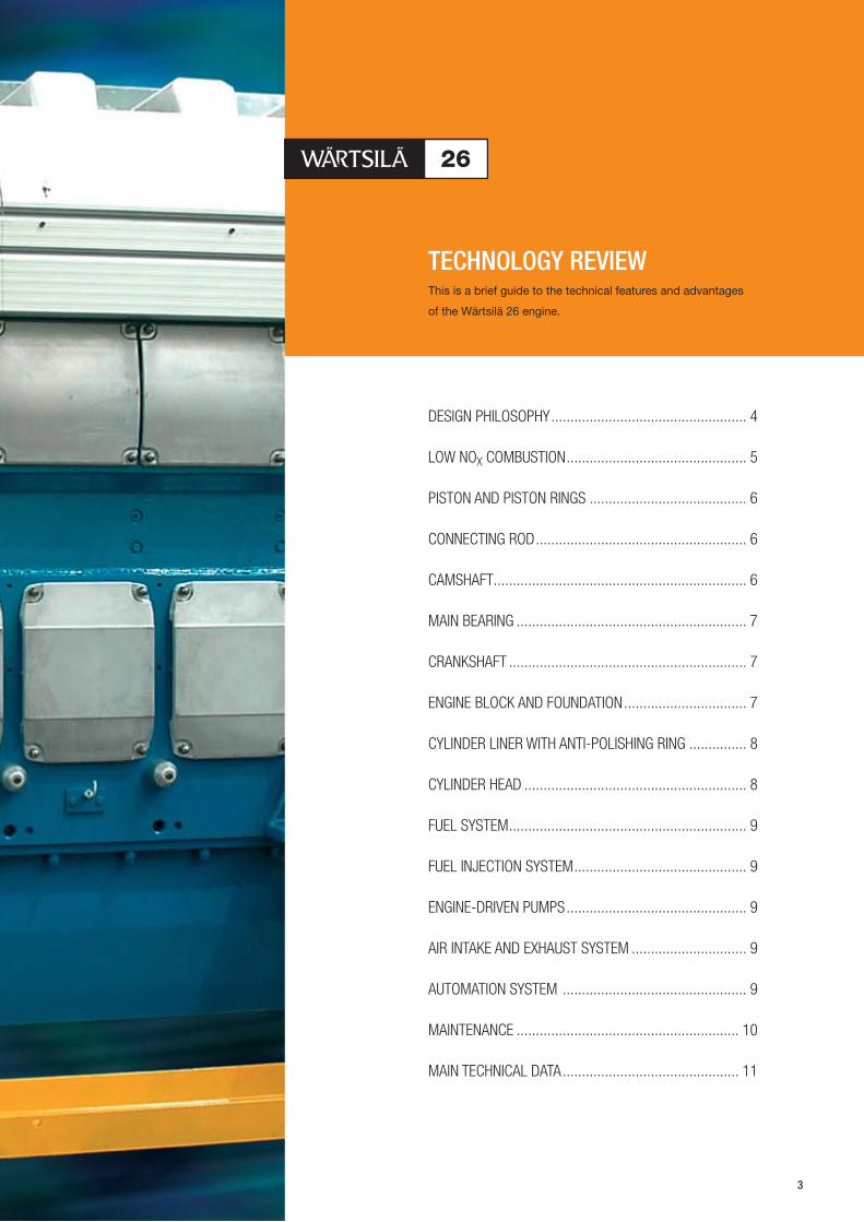
This is a brief guide to the technical features and advantages
of the Wärtsilä 26 engine.
TECHNOLOGY REVIEW
DESIGN PHILOSOPHY................................................... 4
LOW NOX COMBUSTION............................................... 5
PISTON AND PISTON RINGS ......................................... 6
CONNECTING ROD....................................................... 6
CAMSHAFT.................................................................. 6
MAIN BEARING ............................................................ 7
CRANKSHAFT .............................................................. 7
ENGINE BLOCK AND FOUNDATION................................ 7
CYLINDER LINER WITH ANTI-POLISHING RING ............... 8
CYLINDER HEAD .......................................................... 8
FUEL SYSTEM.............................................................. 9
FUEL INJECTION SYSTEM............................................. 9
ENGINE-DRIVEN PUMPS............................................... 9
AIR INTAKE AND EXHAUST SYSTEM .............................. 9
AUTOMATION SYSTEM ................................................ 9
MAINTENANCE .......................................................... 10
MAIN TECHNICAL DATA.............................................. 11
�

Dry cargo vessel Morgenstond is equipped with a Wärtsilä 9L�6 engine.
Naval vessel De Zeven Provincien is equipped with two Wärtsilä 16V�6 engines.
Dredger Daniel Laval is equipped with two Wärtsilä 9L�6 engines.
�
Semi-submersible platform Thunder Horse PDQ is equipped with a Wärtsilä 1�V�00 engine, two 6L�0 engines, two 18V�6 engines and two 18V�� LNE engines.
Fishing vessel Nordoytrål is equipped with a Wärtsilä 1�V�6 engine.
DESIGN PHILOSOPHY Wärtsilä engine designs are based on
generations of know-how combined with
innovations in response to customer needs.
They are also fully optimized for today’s flexible
manufacturing methods.
The WÄRTSILÄ® 26 engine offers the following
core values:
• Easy space-saving installation
• Easy to install
• High availability
• Environmental friendliness
• Low operating costs.
The Wärtsilä 26 was developed in response
to a need in the market for a new engine in
the 260 mm cylinder bore class. The Wärtsilä
26 represents the latest technical advances,

LOW NOX COMBUSTION
IMO NOX COMPLIANCE Any hydrocarbon fuel can be burned provided
the fuel temperature is right and there is
sufficient oxygen. However, the way it is burned
has a great effect on the engine’s thermal
efficiency and exhaust emissions, particularly
NOX formation. The Wärtsilä 26 has been
developed to perform with the optimum load
acceptance and efficiency, while keeping
emission levels substantially below the
limits set by the IMO (International Maritime
Organization). The engine is delivered with
an EIAPP (Engine International Air Pollution
IMO NOX LIMIT FOR NEW ENGINES
20
18
16
14
12
10
8
6
0 200 400 600 800 1000 1200 1400 1600 1800 2000
IMO/MPEC/BCH: NO limit as a function of engine speed X
Wärtsilä 26 low NO combustionX
Rated engine speed (rpm)
Specific NO emissions weighted (g/kWh) X
Prevention) Statement of Compliance as
well as a Technical File listing the parts that
influence NOX formation to enable correct
identification of these parts.
The combustion is optimized by means of a:
High compression ratio that ensures a
higher combustion air temperature to
reduce the ignition delay, and a
High fuel injection pressure for short
injection duration, making the combustion
take place at the optimal point with respect
to efficiency and reduction of NOX.
•
•
5
combining fuel economy and low emission
rates with high fuel versatility. The shortest
and lowest engine in its class, the Wärtsilä 26
requires minimum space in the engine room.
Wärtsilä works in close co-operation with
its customers when conducting field tests and
monitoring selected test components. This has
resulted in satisfied customers: 720 engines
have been manufactured or are on order since
the new design in 1996.
With fewer parts, lower maintenance
requirements, low fuel consumption, less
emissions, and the ability to run reliably
on a variety of fuels, the Wärtsilä 26 is
unquestionably the state-of-the-art in marine
propulsion.

PISTON AND PISTON RINGS The piston design consists of a forged
steel crown and nodular cast iron skirt with
pressurized skirt lubrication. The three-ring
pack comprises two ceramic chromium-plated
compression rings and an oil distributor ring.
This ring pack ensures optimum pressure
distribution and reduces lubricating oil
consumption. The combustion chamber
ensures efficient combustion at all loads, while
the component temperatures are kept low.
CONNECTING ROD The connecting rod has a horizontally-split
bottom end to obtain minimal length and high
rigidity. It has only one single drilled hole,
without plugs, for the flow of lubricating oil
to the piston, securing oil supply under all
circumstances without risk of leakage.
CAMSHAFT The camshaft is composed of individual single-
cylinder units with bolted flange connections to
separate journals. The flanges are formed by
cams, allowing maximum rigidity for the fuel
cam loads. Valve tappets are built into modules
integrated in the engine block, which ensures
easy maintenance and reliable operation.
6

MAIN BEARING The geometry of the main bearing creates
an oil film thickness which greatly exceeds
the safety margins set by the bearing
manufacturers, in accordance with the ‘Thick
Pad’ philosophy of Wärtsilä. The studs and nuts
of the bearing caps are hydraulically tensioned.
CRANKSHAFT Special attention has been given to optimizing
the various geometrical characteristics, such
as cylinder distance, to achieve a space-saving
solution. Three-dimensional finite-element
analysis has been used to achieve the optimal
result with maximum overall rigidity and
moderate bearing loads. All criteria of the
classification societies are met with large
margins. The engine can be delivered with a
100% power take-off shaft at the free end.
ENGINE BLOCK AND FOUNDATION The combination of design elements such as
underslung crankshaft, integral air receiver,
short cylinder distances, and material choice
has resulted in a very rigid engine block.
The camshaft bearing environment
forms an integral part of the engine block,
contributing to its overall stiffness and
taking the large forces caused by actuation
of the fuel pumps. Bolted-on engine feet
facilitate installation in all kinds of seating
arrangements, including resilient mounting.
7
8
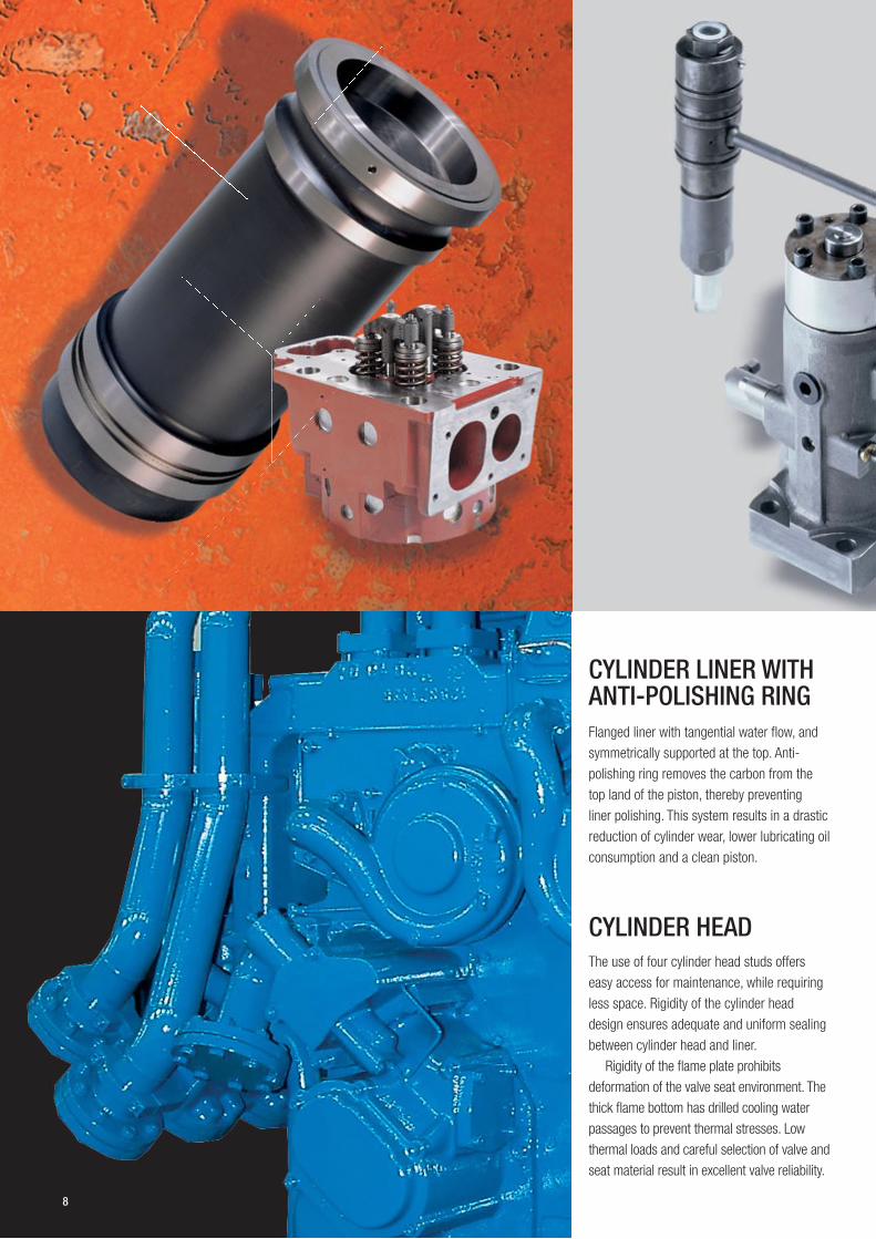
CYLINDER LINER WITH ANTI-POLISHING RING Flanged liner with tangential water flow, and
symmetrically supported at the top. Anti-
polishing ring removes the carbon from the
top land of the piston, thereby preventing
liner polishing. This system results in a drastic
reduction of cylinder wear, lower lubricating oil
consumption and a clean piston.
CYLINDER HEAD The use of four cylinder head studs offers
easy access for maintenance, while requiring
less space. Rigidity of the cylinder head
design ensures adequate and uniform sealing
between cylinder head and liner.
Rigidity of the flame plate prohibits
deformation of the valve seat environment. The
thick flame bottom has drilled cooling water
passages to prevent thermal stresses. Low
thermal loads and careful selection of valve and
seat material result in excellent valve reliability.

FUEL SYSTEM Fuel feed and return lines are integrated in
the fuel pump housing. This results in fewer
pipe connections and therefore high reliability.
Shielded high-pressure lines and the ‘hot box’
design contribute to safety, especially in heavy
fuel operation. The pressure pulses in the low-
pressure system are very low.
FUEL INJECTION SYSTEM The Wärtsilä 26 fuel injection system achieves
the optimum fuel spray pattern and droplet
size. Proper dimensioning of the camshaft,
camshaft bearings and rollers ensures long
lifetimes and low maintenance costs.
ENGINE-DRIVEN PUMPS Engine-driven lubricating oil and cooling water
pumps are an integral part of the engine.
All pumps are located on the free end of the
engine, allowing easy connection to the ancillary
systems. Using engine-driven pumps reduces
the total investment costs for the shipowner.
AIR INTAKE AND EXHAUST SYSTEM Turbochargers are designed for high
compression ratios and high efficiencies at all
loads. The charge air receiver is designed for
minimum pressure variation and good engine
‘breathing’. The exhaust system has a flow-
optimized design. Its modular construction
ensures easy assembly.
Insulation is provided by insulating panels
which are easily removable for inspection.
The V-engine is equipped with a two-stage
charge air cooler to maximize the heat to be
recovered. The charge air cooler is housed in a
multifunctional casting which also incorporates
the turbocharger support.
AUTOMATION SYSTEM The engine is equipped with a scaleable
engine automation system:
• The basic version (UNIC C1) consists of
a hardwired system containing sensors,
switches and handles the basic engine
safeties.
• The extended automation system (UNIC
C2) is a complete electronic engine
control system including speed governing
functions.
The two systems differ in the way signals are
handled and in the amount of functionality
covered by the system. Both systems include
all start and stop related functions. The
advanced control system generates alarms
and load reduction requests when set point
values are exceeded and has speed governing
unit integrated. In the basic automation system
these functionalities must be foreseen in the
external system.
9
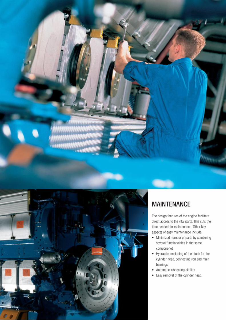
MAINTENANCE
The design features of the engine facilitate
direct access to the vital parts. This cuts the
time needed for maintenance. Other key
aspects of easy maintenance include:
• Minimized number of parts by combining
several functionalities in the same
componenet
• Hydraulic tensioning of the studs for the
cylinder head, connecting rod and main
bearings
• Automatic lubricating oil filter
• Easy removal of the cylinder head.
10

MAIN TECHNICAL DATA
Main assembly shop for Wärtsilä �6 engines in Trieste, Italy.
Cylinder bore 260 mm Piston stroke 320 mm Speed 900 - 1 000 rpm Mean effective pressure 24.3 - 23.0 bar Piston speed 9.6 - 10.7 m/s Voltage 0.4 – 13.8 kV Alternator efficiency 0.95 – 0.96 Fuel specification: Fuel oil 730 cSt/50°C
7200 sR1/100°F ISO 8217, category ISO-F-RMK 700
SFOC 186-192 g/kWh at ISO condition ± 5% tolerance
Rated power: Propulsion engines Output in kW/bhp at 900 rpm Output in kW/bhp at 1 000 rpm
Engine type kW bhp kW bhp 6L26 1 950 2 651 2 040 2 774 8L26 2 600 3 535 2 720 3 698 9L26 2 925 3 977 3 060 4 160
12V26 3 900 5 303 4 080 5 547 16V26 5 200 7 070 5 440 7 396
Principal engine dimensions (mm) and weights (tonnes)
Engine type A* A B* B C*
W6L26 4 251 4 111 1 882 1 801 1 912 1 883 W8L26 5 156 4 939 2 020 1 825 1 912 1 979 W9L26 5 546 5 329 2 020 1 825 1 912 1 979 W12V26 5 218 4 968 2 074 2 074 2 453 2 453 W16V26 6 223 5 973 2 151 2 151 2 489 2 489
F F Weight Weight D dry sump wet sump dry sump wet sump W6L26 2 430 N.y.a. 950 17.0 17.2 W8L26 2 430 N.y.a. 950 21.6 21.9 W9L26 2 430 N.y.a. 950 23.3 23.6 W12V26 2 060 800 1 110 28.7 29.0 W16V26 2 060 800 1 110 36.1 37.9
* Turbocharger at flywheel end.
Rated power: Generating sets Output at 900 rpm/60 Hz Output at 1000 rpm/50Hz
Engine type kW kWe kW kWe 6L26 1 950 1 882 2 040 1 969 8L26 2 600 2 509 2 720 2 625 9L26 2 925 2 823 3 060 2 953
12V26 3 900 3 764 4 080 3 937 16V26 5 200 5 018 5 440 5 250
Principal generating set dimensions (mm) and weights (tonnes) Engine type A A* C L Weight**
6L26 7 345 6 546 2 300 73 020 37.7 8L26 8 243 8 167 2 300 3 125 42.9 9L26 8 853 8 731 2 300 3 125 47.5
12V26 8 353 N.A. 2 984 3 634 59.3 16V26 9 752 N.A. 2 990 3 711 68.8
Gen. output based on generator efficiency of 96.5%. * Turbocharger at flywheel end. **Dependent on generator type and size.
C
11

Wärtsilä Finland Oy P.O.Box 252, FI-65101 Vaasa, Finland l Tel. +358 10 709 0000 l Fax +358 6 356 7188
Wärtsilä enhances the business of its customers by providing them with
complete lifecycle power solutions. When creating better and environmentally
compatible technologies, Wärtsilä focuses on the marine and energy markets
with products and solutions as well as services.
Through innovative products and services, Wärtsilä sets out to be the most
valued business partner of all its customers. This is achieved by the dedication
of more than 13,000 professionals manning 130 Wärtsilä locations in close to
70 countries around the world.
WÄRTSILÄ® is a registered trademark. Copyright © 2006 Wärtsilä Corporation.
12.2
006
/ B
ock´
s O
ffice
/ W
aasa
Gra
phi
cs