WIRELESS ALARM SYSTEM WITH TELEPHONE AUTO · PDF fileWIRELESS ALARM SYSTEM WITH TELEPHONE AUTO...
7
WIRELESS ALARM SYSTEM WITH TELEPHONE AUTO DIALER Our WIRELESS ALARM SYSTEM WITH TELEPHONE AUTO DIALER is designed to allow you to create your own security system. When the AUTO DIALER is connected to a telephone land line and an electrical outlet and set to ARM mode it will alert you when any of the sensors have been triggered. The auto-dialer will activate the built-in siren or chime (if set) and dial out (if set) to up to 5 pre-programmed telephone numbers with your own pre-recorded message. You can choose to remotely listen in & broadcast to the protected perimeter. Once you know the situation, you can take appropriate actions. There are no monthly fees to pay! www.idealalert.ca SK634 BAT.LOW AC “THE SYSTEM THAT CALLS YOU! ”
Transcript of WIRELESS ALARM SYSTEM WITH TELEPHONE AUTO · PDF fileWIRELESS ALARM SYSTEM WITH TELEPHONE AUTO...

WIRELESS ALARM SYSTEM WITH TELEPHONE AUTO DIALER
Our WIRELESS ALARM SYSTEM WITH TELEPHONE AUTO DIALER is designed to allow you to create your own security system. When the AUTO DIALER is connected to a telephone land line and an electrical outlet and set to ARM mode it will alert you when any of the sensors have been triggered. The auto-dialer will activate the built-in siren or chime (if set) and dial out (if set) to up to 5 pre-programmed telephone numbers with your own pre-recorded message. You can choose to remotely listen in & broadcast to the protected perimeter. Once you know the situation, you can take appropriate actions.
There are no monthly fees to pay!
www.idealalert.ca SK634
BAT.LOW AC
“THE SYSTEM THAT CALLS YOU!”

TELEPHONE AUTO DIALER
DESCRIPTION OF COMPONENTS
1. Antenna Jack 2. Antenna 3. LCD Display 4. Speaker
5. REC./Play LED 6. Battery Low LED 7. Power LED 8. Numeric Keypad
9. MIC 10. To wall Jack 11. To Telephone 12. DC 9V Jack
13. Battery Cover 14. Reset button 15. Buzzer 16. Input Terminal
FEATURES
• Receives signals from wireless sensors - activates Telephone auto-dialer and alarm
• Room monitor by telephone function• Programmable voice message for telephone alert • ARM or DISARM system by telephone • Programmable password• Entry delay timing (set time for how long after trigger event
before the auto dialer will dial out and siren will sound) • Up to 5 emergency telephone numbers (up to 32 digits
each) (only last 16 digits appear on LCD screen) • Programmable auto dialing cycle (number of times the
auto dialer will dial each programmed phone number) up to 5 cycles
• Built-in 105 dB alarm (with programmable alarm on/off) • HOME mode function (auto dialer will chime but not dial
out when sensors are triggered) 16 Digit, large number
display • 10 zone icons for easy differentiation of sensor locations• Zone 1 - 8: Can link one wireless sensor to each zone• Zone 9: Can link up to 8 wireless sensors • REMOTE zone: Can link up to 8 remote controls• Recordsthefivemostrecenttriggeredalarms• Built-inflashmemorytoprotectsystemdataduringa
power failure. If the battery dies, all info will remain in auto dialer except the date and time.
• Battery Low indicator. We recommend that the battery in the dialer be changed at least once per year, as you change your smoke detector battery.
• Wired sensor input terminal (to connect Ideal’s wired window and door contacts SK619)
• AC adaptor and 9V battery back-up (included) • Wall mountable (screws and anchors included)
INSTALLATION
NOTE: The Dialer Unit must be installed where it has access to a land line and an electrical outlet.• Install 9V battery included (Fig 1). The battery installed in this unit is a back-up battery only. This battery will keep the unit
working for a limited time during a power failure. • Position the antenna vertically (straight up) for better reception. (Fig. 2)
• Connect the included phone cord to the jack on the control unit labeled “LINE”. Connect the other end of the cord to your
wall jack. (Fig. 3a)NOTE:IfyouareusingaDSLservice,aDSLfiltermustbeinstaledbetweentheautodialerandthewalljack.• A phone can be connected to the unit using the “TEL” jack. (Fig. 3a) Check to see if you have a dial tone.• Connect the AC adaptor to the DC 9V jack on the auto-dialer. (Fig. 3b)
Thank you for choosing Ideal Security’s Home Security System with Telephone Auto Dialer. If you have any questions, problems or comments regarding the installation or operation of this system, please do not hesitate to contact IDEAL’s customer service department through our web site at www.idealalert.ca, via email at [email protected], or by calling our toll free number at 800-361-2236 x 230. Normal business hours 7:30 AM to 3:00 PM Eastern time. Monday to Friday.Occasionally instructions have errors or omissions, please check for updates to these instructions, security tips and other valuable information at www.idealalert.ca
THIS PACKAGE INCLUDES: • 1 AUTO DIALER • 2 REMOTE CONTROLS • 2 WINDOW / DOOR CONTACTS
• 1 MOTION SENSOR • 1 INDOOR/ OUTDOOR SIREN WITH LED STROBE• ALL BATTERIES AND AC/DC ADAPTERS.
NOTE: BEFORE PERMANENTLY INSTALLING ANY OF THE DEVICES INCLUDED IN THIS PACKAGE PLEASE TEST THE RANGE OF ALL UNITS TO MAKE SURE THAT THE RECEIVER PICKS UP ALL THE SENSORS.NOTE: THE TELEPHONE DIALER REQUIRES AN ELECTRICAL OUTLET AND A TELEPHONE LAND LINE WITH TONE DIALING TO MAKE OUTGOING CALLS.
SETUP OVERVIEW
• Set your passcode (refer to AUTO-DIALER SET-UP section 1)• Program telephone numbers (refer to AUTO-DIALER SET-UP setting section 4)• Recordyournotificationmessage(refertoAUTO-DIALERSET-UPsettingsection2)• Install Door/Window sensors (refer to INSTALLATION OF SENSORS section)• Install Motion sensors (refer to INSTALLATION OF SENSORS section)
It’s done! You can now activate the system and be protected with this simple, effective wireless security system with auto dialer.
NOTE: you can change the default settings and expand the system by following the detailed instructions provided in this manual.
IMPORTANT SAFETY TIPS
1. Do not install the system where it will be exposed to direct sunlight or rain. 2. The built-in siren is very loud, never put the system close to your ear. 3. The system should be installed away from heat sources such as radiators, heating ducts and stoves. 4. If the system sounds at random, it is possible that the installed location is too close to a heat source, changing the location or direction of the unit may correct the problem. 5. The system can provide valuable protection for your home and property if utilized properly. However, this unit cannot guarantee complete protection against burglary or property damage. Therefore, we will not be responsible for any losses or damages which may occur, while using this product.
ANSWERING MACHINES AND REMOTE COMMUNICATION.
If you intend to use the REMOTE ACTIVATION features (controlling the alarm unit remotely) of the Auto Dialer, you cannot use an answering machine.To use the remote activation feature: Set the auto dialer to respond (pick up) before your answering machine responds. For example, if your answering machine is set to pick up after 5 rings then set the auto dialer to pick up after 3 rings, this way yourAUTODIALERwillpickupfirst,allowingyoutoenteryourkeyselection.Completeinstructionsonsettinguptheremoteactivation follow.If the answering machine is required, then the REMOTE ACTIVATION feature cannot be used. Set the auto dialer to respond after your answering machine normally responds (set it to 10 rings) this will ensure that the answeringmachineisfirsttorespond.
OP
EN
121110
1514
13 16
TEL.LINE
• PressARM/DISARMbuttontoconfirm.• You are now ready to program up to 5 emergency telephone numbers. Press the */UP or #/DOWN buttons to select
memory location from 1 to 5. If you select 2 this is where your number will be stored and it will be the 2nd number dialed. • Enter the telephone number you would like to store, as you would normally dial it in your area (maximum of 32 digits, the
screenwillonlydisplaythelast16digits),followedbyARM/DISARMtoconfirm.• Repeat steps for the four other numbers you may wish to store. • Press PROG button eight (8) times to exit the set-up mode.
5. TO DELETE A TELEPHONE NUMBER FROM MEMORY
• Enter password followed by PROG button twice (2). • “MEMORY”willflashontheauto-dialerscreen.• PressARM/DISARMbuttontoconfirm.• Press */UP or #/DOWN buttons to select the number you want to delete. • Press DEL./PAUSE button to delete the number. • PresstheARM/DISARMbuttontoconfirm.• Press PROG button eight (8) times to exit the set-up mode.
6. PAUSE FUNCTION
The “PAUSE” function can be stored as one digit in the telephone number memory for some dialing operations. Every one PAUSE in the memory dialing sequence will pause for 3.6 seconds. For example, if you want to store telephone number 514-363-1030 EXTENSION 230 to memory location 2, the operation will be as following:• Enter password then press PROG button twice (2). • “MEMORY”willflashontheauto-dialerscreen.• PressARM/DISARMbuttontoconfirm.• Press */UP or #/DOWN button to select memory location 2.• Enter 5143631030 press and hold DEL./PAUSE for 2 seconds until the letter F appears on the screen, then enter 230.• PressARM/DISARMbuttontoconfirm.• Press PROG button eight (8) times to exit set-up mode.
7. TO PROGRAM AUTO CALL FUNCTION ON/OFF
The auto-dialer has been factory pre-set with the call option ON. If you do not want the auto dialer to call out change this to OFF:• EnterpasswordfollowedbyPROGbuttonfive(5)times.• The “ ”iconwillflashontheauto-dialerscreen.• PressARM/DISARMbuttontoconfirm.• Using*/UPor#/DOWNbuttonstoselectcallOFFfollowedbytheARM/DISARMbuttontoconfirm.• PressPROGbuttonfive(5)timestoexittheset-upmode.
8. TO PROGRAM AUTO DIALING CYCLE (how many times the auto dialer will call the programed numbers).
The auto-dialer has been factory pre-set to auto dial for 1 cycle (When a sensor is triggered the auto dialer will call all stored numbers 1 time). You can change the number of cycles from 1 to 5 dialing cycles. • Enter password followed by PROG button six (6) times.• “CYCLE”willflashontheauto-dialerscreen.• PressARM/DISARMbuttontoconfirm.• Using */UP and #/DOWN buttons to select number of cycles between 1 and 5
followedbytheARM/DISARMbuttontoconfirm.• Press PROG button four (4) times to exit set up mode.
9. TO TEST MEMORY DIALING
In standby mode, press and hold the PROG button for at least 3 seconds, you will hear a short beep. Key in the memory locationofthetelephonenumber,i.e.1–5.Thetelephonenumberstoredinspecifiedmemorylocationwillautomaticallybedialed. Press the PROG button to stop the dialing. The auto dialer must be connected to a land line in order for this function to work. If not connected then you will hear 4 short beeps.
( Fig. 3a )
TEL.LINE
( Fig. 3b )
DC 9V Adaptor
TEL.LINE
• Wall mount option: Choose a suitable location where you have access to a telephone line and electrical outlet, drill holes, using template provided and install anchors and screws. Place the auto-dialer over the screws and slide it down to secure it in place.
AUTO-DIALER SET-UPNOTE: If no key is pressed for 20 seconds, the auto-dialer will automatically exit set-up mode. • Set-up is done in DISARM mode only. • The auto-dialer has a factory preset password of 0-0-0. This should be changed to your own personal password.
1. TO CHANGE PASSWORD
• Enterfactorypre-setpassword0-0-0.PressPROGbuttononce(1),PASSWORDwillflashontheauto-dialerscreen.• PresstheARM/DISARMbuttontoconfirmthatyouwanttoenterthePASSWORD.• EnteryournewpasswordthenpresstheARM/DISARMbuttontoconfirmyourpasswordhasbeenstored
(you can choose from 3 to 6 digits for your password). • Press the PROG button nine (9) times to exit set-up mode.NOTE: PASSWORD RESET If you forget your password, locate the RESET button on the back of the unit. Press and hold the PROG button, and, press and release the reset button once. The screen will go blank. When screen returns let go of the PROG button. You now have the factory pre-set password of 0-0-0. This will reset the password ONLY, all other information will remain (programmed telephone numbers and learned sensors)
2. RECORD PERSONALIZED NOTIFICATION MESSAGE
Youcanrecordasinglepersonalized20secondmessagethatwillbeplayedbackwhenyoureceivetelephonenotificationthat your system has been triggered. To help remember the options you have, your message should be similar to: “[Your name’s] security system has been triggered, please enter a command; to Monitor Room press 1 plus #, to Broadcast press 2 plus #, to End Call press 3 plus #, to Disarm System and end call press 6 plus #.”
• Enter password then press REC/PLAY once. • Clearly and slowly dictate your 20 second message. • Press REC/PLAY to end recording. The recording will automatically end after 20 seconds. The message will replay once
afterrecordingisfinished.• Press REC>/PLAY to replay message at anytime.
3. SETTING THE TIME (YEAR / MONTH / DATE / HOUR / MINUTES)
• Enter password then press the PROG button nine (9) times. • Willflashontheauto-dialerscreen.• PressARM/DISARMbuttontoconfirm.• Thedatewillshowontheauto-dialerscreenasfivesetsofnumbers:year,month,anddatefollowedbythetimehourand
minutes(24hr.timeclock).Thefirstsetofnumberswillflashconfirmingthatthesecannowbechanged.• Enter correct year by pressing */UP or #/DOWN button, then press the ARM/DISARM button. The next set of numbers will
startflashing,enterthemonthbypressing*/UPor#/DOWNbutton,thenpresstheARM/DISARMbutton.Continueuntilyou have the correct date and time.
• Press PROG button once (1) to exit set-up mode.
4. TO PROGRAM EMERGENCY TELEPHONE CALL NUMBERS
• Enter password followed by PROG button twice (2). • MEMORYwillflashontheauto-dialerscreen.
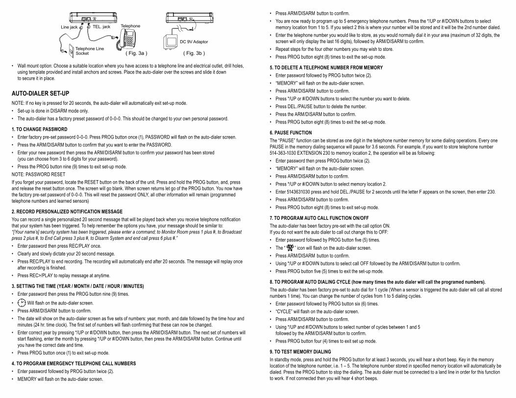
• The detection range (left to right) is 110 degrees for a distance up to 8m (16'). • Test the area requiring coverage before mounting the sensor permanently.• Use the swivel wall mount bracket to mark the mounting location, drill holes and install anchors and attach the bracket
with the screws provided. Slide the main unit onto the bracket until it clicks into place (Fig 5). Adjust the bracket to obtain the best coverage of the intended protected area (Fig 6).
The Motion Sensor included with this kit is factory linked to the auto dialer
1.5~2m(5’~6’)
5~8m (16~26’)
110°
(Fig. 6)
(Fig. 5)
BATTERY LOW INDICATOR
Whenthebatteryislow,theLEDonthefrontoftheunitwillflashon3secondsandoff1second.Replacethebattery immediately to maintain proper detection. If batteries are low they may send a false signal to the auto-dialer. Batteries in all units should be replaced at least once per year like your smoke detectors.
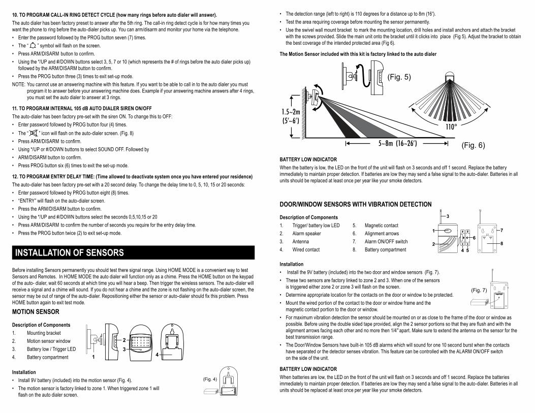
DOOR/WINDOW SENSORS WITH VIBRATION DETECTION
1
2
3
4 5
67
8
Description of Components
1. Trigger/ battery low LED 5. Magnetic contact2. Alarm speaker 6. Alignment arrows3. Antenna 7. Alarm ON/OFF switch 4. Wired contact 8. Battery compartment
Installation
• Install the 9V battery (included) into the two door and window sensors (Fig. 7).
(Fig. 7)
• These two sensors are factory linked to zone 2 and 3. When one of the sensors istriggeredeitherzone2orzone3willflashonthescreen.
• Determine appropriate location for the contacts on the door or window to be protected. • Mount the wired portion of the contact to the door or window frame and the
magnetic contact portion to the door or window. • For maximum vibration detection the sensor should be mounted on or as close to the frame of the door or window as
possible.Beforeusingthedoublesidedtapeprovided,alignthe2sensorportionssothattheyareflushandwiththealignment arrows facing each other and no more then 1/4" apart. Make sure to extend the antenna on the sensor for the best transmission range.
• The Door/Window Sensors have built-in 105 dB alarms which will sound for one 10 second burst when the contacts have separated or the detector senses vibration. This feature can be controlled with the ALARM ON/OFF switch on the side of the unit.
BATTERY LOW INDICATOR
Whenbatteriesarelow,theLEDonthefrontoftheunitwillflashon3secondsandoff1second.Replacethebatteriesimmediately to maintain proper detection. If batteries are low they may send a false signal to the auto-dialer. Batteries in all units should be replaced at least once per year like your smoke detectors.
10. TO PROGRAM CALL-IN RING DETECT CYCLE (how many rings before auto dialer will answer).
The auto dialer has been factory preset to answer after the 5th ring. The call-in ring detect cycle is for how many times you want the phone to ring before the auto-dialer picks up. You can arm/disarm and monitor your home via the telephone.• Enter the password followed by the PROG button seven (7) times. • The “ ”symbolwillflashonthescreen.• PressARM/DISARMbuttontoconfirm.• Using the */UP and #/DOWN buttons select 3, 5, 7 or 10 (which represents the # of rings before the auto dialer picks up)
followedbytheARM/DISARMbuttontoconfirm.• Press the PROG button three (3) times to exit set-up mode.NOTE: You cannot use an answering machine with this feature. If you want to be able to call in to the auto dialer you must program it to answer before your answering machine does. Example if your answering machine answers after 4 rings, you must set the auto dialer to answer at 3 rings.
11. TO PROGRAM INTERNAL 105 dB AUTO DIALER SIREN ON/OFF
The auto-dialer has been factory pre-set with the siren ON. To change this to OFF:• Enter password followed by PROG button four (4) times. • The “ ”iconwillflashontheauto-dialerscreen.(Fig.8)• PressARM/DISARM toconfirm.• Using */UP or #/DOWN buttons to select SOUND OFF. Followed by• ARM/DISARMbuttontoconfirm.• Press PROG button six (6) times to exit the set-up mode.
12. TO PROGRAM ENTRY DELAY TIME: (Time allowed to deactivate system once you have entered your residence)
The auto-dialer has been factory pre-set with a 20 second delay. To change the delay time to 0, 5, 10, 15 or 20 seconds:• Enter password followed by PROG button eight (8) times. • “ENTRY”willflashontheauto-dialerscreen.• PresstheARM/DISARMbuttontoconfirm.• Using the */UP and #/DOWN buttons select the seconds 0,5,10,15 or 20• PressARM/DISARM toconfirmthenumberofsecondsyourequirefortheentrydelaytime.• Press the PROG button twice (2) to exit set-up mode.
INSTALLATION OF SENSORS Before installing Sensors permanently you should test there signal range. Using HOME MODE is a convenient way to test Sensors and Remotes. In HOME MODE the auto dialer will function only as a chime. Press the HOME button on the keypad of the auto- dialer, wait 60 seconds at which time you will hear a beep. Then trigger the wireless sensors. The auto-dialer will receiveasignalandachimewillsound.Ifyoudonothearachimeandthezoneisnotflashingontheauto-dialerscreen,thesensormaybeoutofrangeoftheauto-dialer.Repositioningeitherthesensororauto-dialershouldfixthisproblem.PressHOME button again to exit test mode.
MOTION SENSOR
Description of Components
1
2
34
1. Mounting bracket 2. Motion sensor window3. Battery low / Trigger LED 4. Battery compartment
Installation (Fig. 4)• Install 9V battery (included) into the motion sensor (Fig. 4).
• The motion sensor is factory linked to zone 1. When triggered zone 1 will flashontheautodialerscreen.
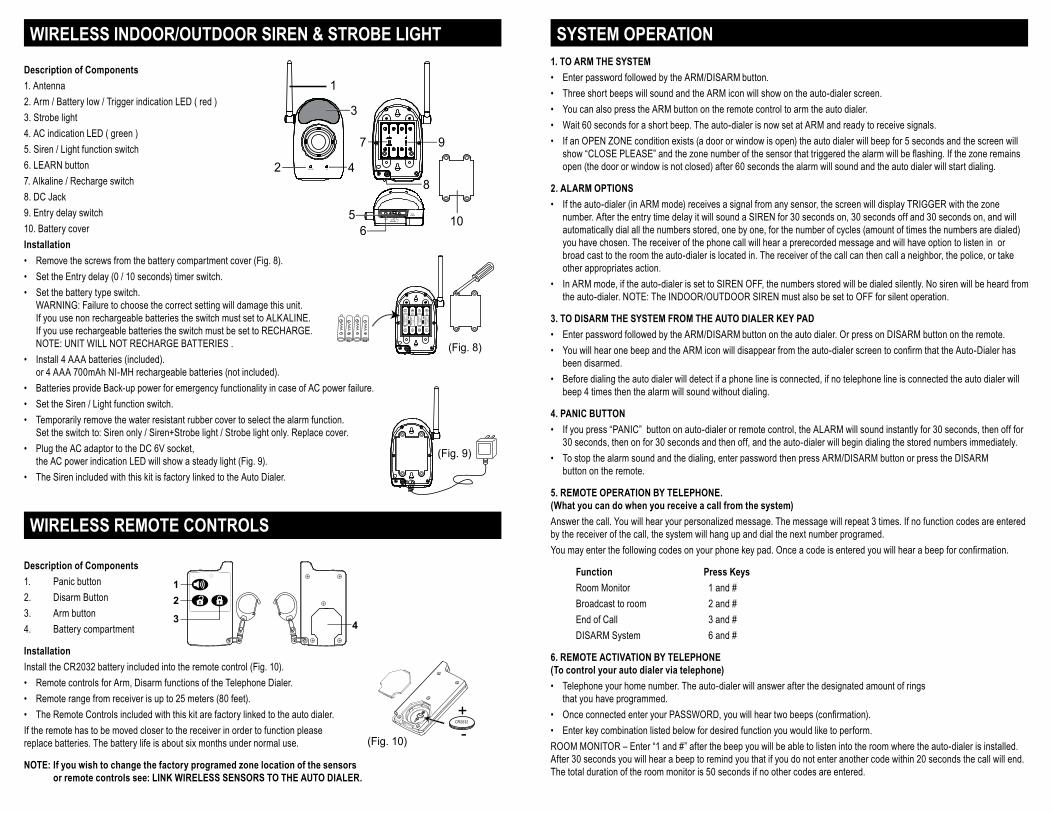
SYSTEM OPERATION1. TO ARM THE SYSTEM
• Enter password followed by the ARM/DISARM button. • Three short beeps will sound and the ARM icon will show on the auto-dialer screen.• You can also press the ARM button on the remote control to arm the auto dialer.• Wait 60 seconds for a short beep. The auto-dialer is now set at ARM and ready to receive signals.• If an OPEN ZONE condition exists (a door or window is open) the auto dialer will beep for 5 seconds and the screen will
show“CLOSEPLEASE”andthezonenumberofthesensorthattriggeredthealarmwillbeflashing.Ifthezoneremainsopen (the door or window is not closed) after 60 seconds the alarm will sound and the auto dialer will start dialing.
2. ALARM OPTIONS
• If the auto-dialer (in ARM mode) receives a signal from any sensor, the screen will display TRIGGER with the zone number. After the entry time delay it will sound a SIREN for 30 seconds on, 30 seconds off and 30 seconds on, and will automatically dial all the numbers stored, one by one, for the number of cycles (amount of times the numbers are dialed) you have chosen. The receiver of the phone call will hear a prerecorded message and will have option to listen in or broad cast to the room the auto-dialer is located in. The receiver of the call can then call a neighbor, the police, or take other appropriates action.
• In ARM mode, if the auto-dialer is set to SIREN OFF, the numbers stored will be dialed silently. No siren will be heard from the auto-dialer. NOTE: The INDOOR/OUTDOOR SIREN must also be set to OFF for silent operation.
3. TO DISARM THE SYSTEM FROM THE AUTO DIALER KEY PAD
• Enter password followed by the ARM/DISARM button on the auto dialer. Or press on DISARM button on the remote.• YouwillhearonebeepandtheARMiconwilldisappearfromtheauto-dialerscreentoconfirmthattheAuto-Dialerhas
been disarmed.• Before dialing the auto dialer will detect if a phone line is connected, if no telephone line is connected the auto dialer will
beep 4 times then the alarm will sound without dialing.
4. PANIC BUTTON
• If you press “PANIC” button on auto-dialer or remote control, the ALARM will sound instantly for 30 seconds, then off for 30 seconds, then on for 30 seconds and then off, and the auto-dialer will begin dialing the stored numbers immediately.
• To stop the alarm sound and the dialing, enter password then press ARM/DISARM button or press the DISARM button on the remote.
5. REMOTE OPERATION BY TELEPHONE. (What you can do when you receive a call from the system)
Answer the call. You will hear your personalized message. The message will repeat 3 times. If no function codes are entered by the receiver of the call, the system will hang up and dial the next number programed. Youmayenterthefollowingcodesonyourphonekeypad.Onceacodeisenteredyouwillhearabeepforconfirmation.
Function Press Keys
Room Monitor 1 and # Broadcast to room 2 and # End of Call 3 and # DISARM System 6 and #
6. REMOTE ACTIVATION BY TELEPHONE (To control your auto dialer via telephone)
• Telephone your home number. The auto-dialer will answer after the designated amount of rings that you have programmed.
• OnceconnectedenteryourPASSWORD,youwillheartwobeeps(confirmation).• Enter key combination listed below for desired function you would like to perform.ROOM MONITOR – Enter “1 and #” after the beep you will be able to listen into the room where the auto-dialer is installed. After 30 seconds you will hear a beep to remind you that if you do not enter another code within 20 seconds the call will end. The total duration of the room monitor is 50 seconds if no other codes are entered.
WIRELESS INDOOR/OUTDOOR SIREN & STROBE LIGHT
Description of Components
10
2
3
4
1
BAT.LOW AC
LEARN
DC 6V56
8
97 ALKALINE
RECHARGE
10S
0S
1. Antenna2. Arm / Battery low / Trigger indication LED ( red )3. Strobe light4. AC indication LED ( green )5. Siren / Light function switch6. LEARN button7. Alkaline / Recharge switch8. DC Jack9. Entry delay switch10. Battery coverInstallation
• Remove the screws from the battery compartment cover (Fig. 8).
AAA
AAA
AAA
AAA
ALKALINE
RECHARGE
10S
0S
(Fig. 8)
• Set the Entry delay (0 / 10 seconds) timer switch.• Set the battery type switch.
WARNING: Failure to choose the correct setting will damage this unit. If you use non rechargeable batteries the switch must set to ALKALINE. If you use rechargeable batteries the switch must be set to RECHARGE. NOTE: UNIT WILL NOT RECHARGE BATTERIES .
• Install 4 AAA batteries (included). or 4 AAA 700mAh NI-MH rechargeable batteries (not included).
• Batteries provide Back-up power for emergency functionality in case of AC power failure.
ALKALINE
RECHARGE
10S
0S (Fig. 9)
• Set the Siren / Light function switch. • Temporarily remove the water resistant rubber cover to select the alarm function.
Set the switch to: Siren only / Siren+Strobe light / Strobe light only. Replace cover.• Plug the AC adaptor to the DC 6V socket,
the AC power indication LED will show a steady light (Fig. 9).• The Siren included with this kit is factory linked to the Auto Dialer.
WIRELESS REMOTE CONTROLS Description of Components
12
3 4
1. Panic button2. Disarm Button3. Arm button4. Battery compartment
Installation
Install the CR2032 battery included into the remote control (Fig. 10).
(Fig. 10)
• Remote controls for Arm, Disarm functions of the Telephone Dialer.• Remote range from receiver is up to 25 meters (80 feet).• The Remote Controls included with this kit are factory linked to the auto dialer.If the remote has to be moved closer to the receiver in order to function please replace batteries. The battery life is about six months under normal use.
NOTE: If you wish to change the factory programed zone location of the sensors or remote controls see: LINK WIRELESS SENSORS TO THE AUTO DIALER.
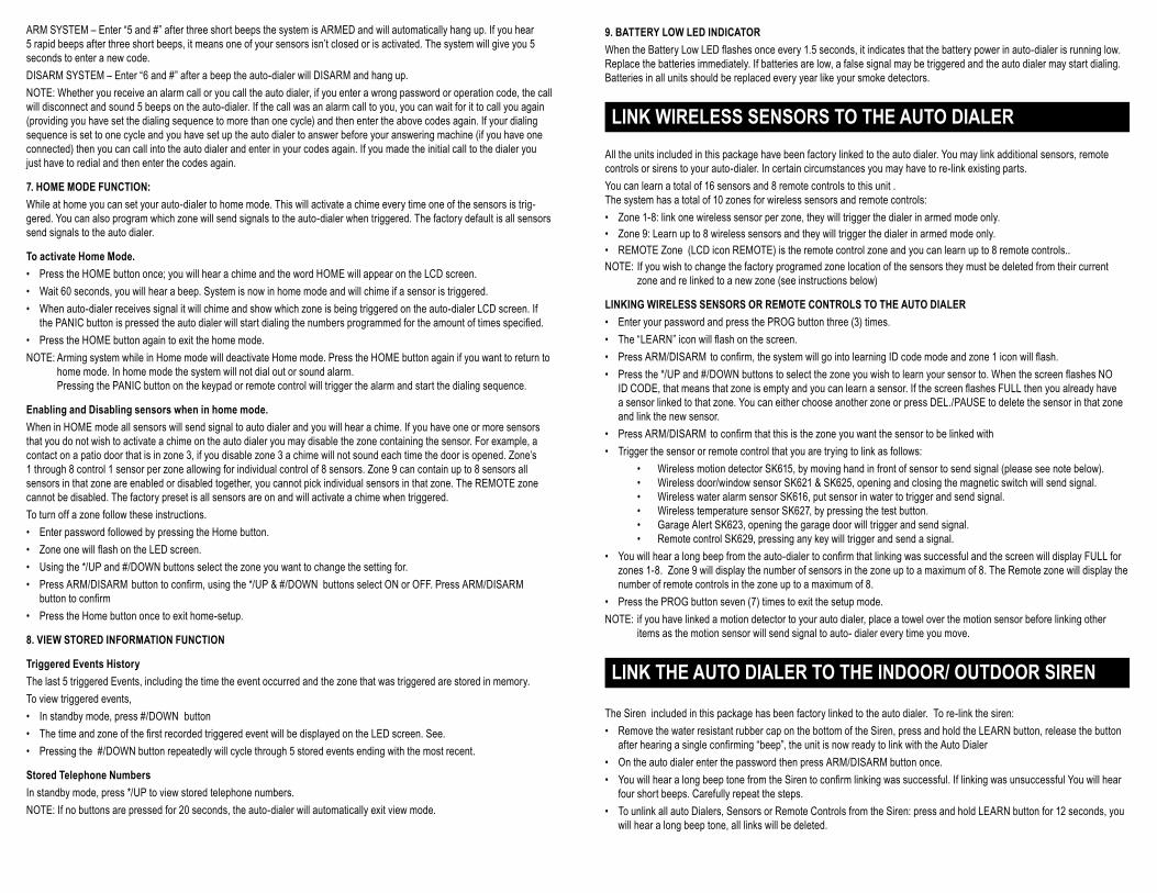
9. BATTERY LOW LED INDICATOR
WhentheBatteryLowLEDflashesonceevery1.5seconds,itindicatesthatthebatterypowerinauto-dialerisrunninglow.Replace the batteries immediately. If batteries are low, a false signal may be triggered and the auto dialer may start dialing. Batteries in all units should be replaced every year like your smoke detectors.
LINK WIRELESS SENSORS TO THE AUTO DIALER All the units included in this package have been factory linked to the auto dialer. You may link additional sensors, remote controls or sirens to your auto-dialer. In certain circumstances you may have to re-link existing parts.You can learn a total of 16 sensors and 8 remote controls to this unit . The system has a total of 10 zones for wireless sensors and remote controls:• Zone 1-8: link one wireless sensor per zone, they will trigger the dialer in armed mode only. • Zone 9: Learn up to 8 wireless sensors and they will trigger the dialer in armed mode only.• REMOTE Zone (LCD icon REMOTE) is the remote control zone and you can learn up to 8 remote controls..NOTE: If you wish to change the factory programed zone location of the sensors they must be deleted from their current zone and re linked to a new zone (see instructions below)
LINKING WIRELESS SENSORS OR REMOTE CONTROLS TO THE AUTO DIALER
• Enter your password and press the PROG button three (3) times. • The“LEARN”iconwillflashonthescreen.• PressARM/DISARM toconfirm,thesystemwillgointolearningIDcodemodeandzone1iconwillflash.• Pressthe*/UPand#/DOWNbuttonstoselectthezoneyouwishtolearnyoursensorto.WhenthescreenflashesNO
IDCODE,thatmeansthatzoneisemptyandyoucanlearnasensor.IfthescreenflashesFULLthenyoualreadyhavea sensor linked to that zone. You can either choose another zone or press DEL./PAUSE to delete the sensor in that zone and link the new sensor.
• PressARM/DISARM toconfirmthatthisisthezoneyouwantthesensortobelinkedwith• Trigger the sensor or remote control that you are trying to link as follows: • WirelessmotiondetectorSK615,bymovinghandinfrontofsensortosendsignal(pleaseseenotebelow). • Wirelessdoor/windowsensorSK621&SK625,openingandclosingthemagneticswitchwillsendsignal. • WirelesswateralarmsensorSK616,putsensorinwatertotriggerandsendsignal. • WirelesstemperaturesensorSK627,bypressingthetestbutton. • GarageAlertSK623,openingthegaragedoorwilltriggerandsendsignal. • RemotecontrolSK629,pressinganykeywilltriggerandsendasignal.• Youwillhearalongbeepfromtheauto-dialertoconfirmthatlinkingwassuccessfulandthescreenwilldisplayFULLfor
zones 1-8. Zone 9 will display the number of sensors in the zone up to a maximum of 8. The Remote zone will display the number of remote controls in the zone up to a maximum of 8.
• Press the PROG button seven (7) times to exit the setup mode.NOTE: if you have linked a motion detector to your auto dialer, place a towel over the motion sensor before linking other items as the motion sensor will send signal to auto- dialer every time you move.
LINK THE AUTO DIALER TO THE INDOOR/ OUTDOOR SIREN
The Siren included in this package has been factory linked to the auto dialer. To re-link the siren:• Remove the water resistant rubber cap on the bottom of the Siren, press and hold the LEARN button, release the button
afterhearingasingleconfirming“beep”,theunitisnowreadytolinkwiththeAutoDialer• On the auto dialer enter the password then press ARM/DISARM button once. • YouwillhearalongbeeptonefromtheSirentoconfirmlinkingwassuccessful.IflinkingwasunsuccessfulYouwillhear
four short beeps. Carefully repeat the steps.• To unlink all auto Dialers, Sensors or Remote Controls from the Siren: press and hold LEARN button for 12 seconds, you
will hear a long beep tone, all links will be deleted.
ARM SYSTEM – Enter “5 and #” after three short beeps the system is ARMED and will automatically hang up. If you hear 5 rapid beeps after three short beeps, it means one of your sensors isn’t closed or is activated. The system will give you 5 seconds to enter a new code. DISARM SYSTEM – Enter “6 and #” after a beep the auto-dialer will DISARM and hang up.NOTE: Whether you receive an alarm call or you call the auto dialer, if you enter a wrong password or operation code, the call will disconnect and sound 5 beeps on the auto-dialer. If the call was an alarm call to you, you can wait for it to call you again (providing you have set the dialing sequence to more than one cycle) and then enter the above codes again. If your dialing sequence is set to one cycle and you have set up the auto dialer to answer before your answering machine (if you have one connected) then you can call into the auto dialer and enter in your codes again. If you made the initial call to the dialer you just have to redial and then enter the codes again.
7. HOME MODE FUNCTION:
While at home you can set your auto-dialer to home mode. This will activate a chime every time one of the sensors is trig-gered. You can also program which zone will send signals to the auto-dialer when triggered. The factory default is all sensors send signals to the auto dialer.
To activate Home Mode.
• Press the HOME button once; you will hear a chime and the word HOME will appear on the LCD screen.• Wait 60 seconds, you will hear a beep. System is now in home mode and will chime if a sensor is triggered.• When auto-dialer receives signal it will chime and show which zone is being triggered on the auto-dialer LCD screen. If
thePANICbuttonispressedtheautodialerwillstartdialingthenumbersprogrammedfortheamountoftimesspecified.• Press the HOME button again to exit the home mode.NOTE: Arming system while in Home mode will deactivate Home mode. Press the HOME button again if you want to return to home mode. In home mode the system will not dial out or sound alarm. Pressing the PANIC button on the keypad or remote control will trigger the alarm and start the dialing sequence.
Enabling and Disabling sensors when in home mode.
When in HOME mode all sensors will send signal to auto dialer and you will hear a chime. If you have one or more sensors that you do not wish to activate a chime on the auto dialer you may disable the zone containing the sensor. For example, a contact on a patio door that is in zone 3, if you disable zone 3 a chime will not sound each time the door is opened. Zone’s 1 through 8 control 1 sensor per zone allowing for individual control of 8 sensors. Zone 9 can contain up to 8 sensors all sensors in that zone are enabled or disabled together, you cannot pick individual sensors in that zone. The REMOTE zone cannot be disabled. The factory preset is all sensors are on and will activate a chime when triggered. To turn off a zone follow these instructions.• Enter password followed by pressing the Home button. • ZoneonewillflashontheLEDscreen.• Using the */UP and #/DOWN buttons select the zone you want to change the setting for. • PressARM/DISARMbuttontoconfirm,usingthe*/UP&#/DOWNbuttonsselectONorOFF.PressARM/DISARM
buttontoconfirm• Press the Home button once to exit home-setup.
8. VIEW STORED INFORMATION FUNCTION
Triggered Events History
The last 5 triggered Events, including the time the event occurred and the zone that was triggered are stored in memory.To view triggered events, • In standby mode, press #/DOWN button• ThetimeandzoneofthefirstrecordedtriggeredeventwillbedisplayedontheLEDscreen.See.• Pressing the #/DOWN button repeatedly will cycle through 5 stored events ending with the most recent.
Stored Telephone Numbers
In standby mode, press */UP to view stored telephone numbers.NOTE: If no buttons are pressed for 20 seconds, the auto-dialer will automatically exit view mode.

TROUBLE SHOOTING GUIDE AUTO-DIALER WILL NOT ARM/DISARM
• Make sure you have entered the correct password, if not, re-enter the password. • If it still does not work, perform the password reset following the instructions in the “CHANGE PASSWORD” section to
reset the auto-dialer. • Retry the ARM/DISARM function.
AUTO-DIALER WILL NOT DIAL
• Make sure the telephone line is connected properly. • Make sure the telephone numbers are stored correctly. • Make sure the auto-dialer is setup for auto-dial mode. • If auto-dialer does not receive a signal from the wireless sensor, re-link the sensor to the dialer following the instructions
in the “LINKING WIRELESS SENSORS TO THE AUTO DIALER” section.
FALSE TRIGGERS
If sensors send false signals, • Ensure that the batteries are still in good operating condition. • Makesurethatthegapsbetweenthecontactandsensoronthewindowanddoorcontactsarenomorethana1⁄4”apart
and that arrows are pointing towards each other. • It is possible that the installed location is too close to a heat source, changing the location or direction of the unit may
correct the problem.
TIPS
• Make sure full telephone numbers have been entered correctly. • Only suitable for single phone line. Not compatible with fax machines or multi line telephones.• Auto Dialer requires a land line and tone dialing
WARNING
All batteries including the back up battery in the telephone dialer should be changed at minimum once per year as the battery in smoke detector is changed. Should a power failure occur and the back up battery is weak, or batteries in any of the sen-sors are weak, false alarms may occur. If the telephone dialer or any other detector is not being used for an extended period, remove the batteries to avoid any damage from battery leakage.
CUSTOMER SERVICE
Thank you for your purchase: Wearededicatedtocustomerserviceandwillworktoresolveanydifficultiestoensurecustomersatisfaction.Ifyouhaveanyquestions about the setup or function of this product, please call us before returning this product to the point of purchase. Our customer service number is: 1 800-361-2236 EXT. 230 (514-363-1030 EXT. 230 local Montreal area)
NOTE: Please preserve this manual. It contains valuable information for properly setting up and operating the system. Please check for updated instructions at www.idealalert.ca
WARRANTY: 1 year limited warranty (excluding batteries) on components.
Ideal Security Inc. www.idealalert.ca e-mail: [email protected] Tel.: 1 800-361-2236 EXT. 230