Temperature Monitor and Alarm · 3 General Description The Refrigerator/Freezer or Property Guard...
24
Refrigerator/Freezer Guard Models VM605, VM605E Property Guard Models VM610, VM610E Temperature Monitor and Alarm Manual and Installation Instructions
Transcript of Temperature Monitor and Alarm · 3 General Description The Refrigerator/Freezer or Property Guard...

Refrigerator/Freezer Guard Models VM605, VM605E
Property Guard Models VM610, VM610E
Temperature Monitor and Alarm
Manual and Installation Instructions

2
Index Page
Wiring Diagram 4
Installing the Guard 5
Accessing the Guard over the phone 6
Programming Temperature Sensor Parameters 6-9
Programming Door Sensor Inputs 9
Programming the Autodialer Functions 10-13
Programming Contact Telephone Numbers 10
Programming Local ID Number 11
Recording a Unit ID Message 11
Programming the Number of Rings 11
Programming PIN Numbers 12
Programming Reminder Calls 12
Programming Warning Message Repetitions 12
Set Temperature Readout Units (°C or °F) 13
Programming Power Outage Delay Time 13
Changing the Callout Delay Time 13
Using the Guard 14
Checking Sensor Inputs Locally 14
Checking Sensor Inputs Remotely 14
Confirming Alarm Conditions Remotely 14
Confirming Alarm Conditions Locally 14
Interpreting the Display 16-17
Frequently Asked Questions 18-20
Trouble-shooting 20
Advanced Network Setup 21
Limited Warranty 22
FCC Part 68 Information 23
General Description 3
3
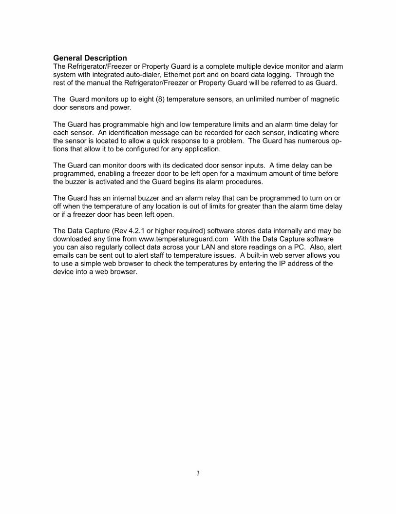
General Description The Refrigerator/Freezer or Property Guard is a complete multiple device monitor and alarm system with integrated auto-dialer, Ethernet port and on board data logging. Through the rest of the manual the Refrigerator/Freezer or Property Guard will be referred to as Guard. The Guard monitors up to eight (8) temperature sensors, an unlimited number of magnetic door sensors and power.
The Guard has programmable high and low temperature limits and an alarm time delay for each sensor. An identification message can be recorded for each sensor, indicating where the sensor is located to allow a quick response to a problem. The Guard has numerous op-tions that allow it to be configured for any application. The Guard can monitor doors with its dedicated door sensor inputs. A time delay can be programmed, enabling a freezer door to be left open for a maximum amount of time before the buzzer is activated and the Guard begins its alarm procedures. The Guard has an internal buzzer and an alarm relay that can be programmed to turn on or off when the temperature of any location is out of limits for greater than the alarm time delay or if a freezer door has been left open. The Data Capture (Rev 4.2.1 or higher required) software stores data internally and may be downloaded any time from www.temperatureguard.com With the Data Capture software you can also regularly collect data across your LAN and store readings on a PC. Also, alert emails can be sent out to alert staff to temperature issues. A built-in web server allows you to use a simple web browser to check the temperatures by entering the IP address of the device into a web browser.

4

5
Installing the Guard:
• Immediately upon removing the Guard from the box, turn it on without plugging it in. This is a test to see if the batteries became dislodged during shipping. If the LCD screen works, turn it back off.
• Select a location with access to power and an analog telephone line.
• Mount the Guard to the wall. Holes are 10cm or 3.937 inches apart.
• Connect the phone line to an active analog telephone jack.
It is recommended that a surge suppresser be used for the phone line.
• Plug the Ethernet cable into the LAN jack. Required if on DHCP network.
• It is recommended that a surge suppresser be used for the power line.
• Plug the power pack into a 120vac power.
• Connect Sensors and Inputs. For ease of wiring, the terminal blocks can be removed. Follow the wiring diagram on the previ-ous page.
Temperature Sensors Locate the sensor so that it will yield an average temperature. If specific items within a fridge or freezer are being monitored, locate the sensors as close as possible to those items. The tempera-ture throughout a fridge or freezer can vary widely.
Door Sensor Inputs Wire closed loop magnetic door sensors to the Door Sensor Inputs to detect when doors are open. Multiple door sensor switches can be wired in series.
Temperature Sensors must be installed before turning on the unit.
• Turn on the Guard by moving the power switch to the “On” position. If sensors are added or re-
moved later, you must turn the unit off, then on again.
Connecting the Guard to your network: Important
• Download the Data Capture software from: http://temperatureguard.com/software.html
• Read the installation instructions before installing!
• Read the manual before continuing.

6
Accessing the Guard over the phone
1) From another phone line call the Guard. The device will pick up after the programmed number of rings (Default is 1).
2) To access all functions, enter the 4-digit "Full Access" PIN. (Factory default is 0000). To access only the "Acknowledge Only" functions, enter the 4-digit “Acknowledge Only” PIN (Factory default
is 1234). The "Acknowledge Only" functions are:
A) Confirming Alarm Conditions Remotely. B) Checking Sensor Inputs Remotely.
3) You will hear the Main Menu options:
Programming Temperature Sensor Parameters
Each temperature sensor has four (4) programmable parameters as well as a programmable tem-perature correction.
Sensor Identification Message. The Sensor ID message will be played when the Guard is report-ing the status of that Sensor. (This must be done over a phone line)
Sensor Low and High Temperature limits. The low and high temperature limit values are pro-grammed in degrees. When a sensor's temperature exceeds either the high or low limit for longer than the programmed callout time delay, that sensor will be in alarm condition. These values can
also be programmed using the Data Capture Software (quicker and easier). Sensor callout time delay. A sensor's temperature must be out of limits for greater than the callout delay time for the sensor to be in alarm condition. These values can also be programmed using the
Data Capture Software (quicker and easier).
Main Menu
Option Function
1 Status
2 Set Limits
3 Program
0 Exit (Hang Up the phone)
# Repeat Warning message (if any input is in alarm condition)
NOT
SPOKEN MENU
ITEM

7
Programming Sensor Parameters 1. Accessing the Sensor Configuration a) From the Main Menu, press 2 to Set Limits.
► The "Full Access" PIN will be requested if the "Acknowledge Only" PIN was entered initially. If the correct "Full Access" PIN is not entered, the Guard will hang up.
b) You will hear “Enter Sensor Number." c) Enter the sensor you want to program (1-8) .
►To return to the Main Menu press 0. d) Proceed to Step 2.a.
2. Programming the Sensor ID Message
a) You will hear "Sensor x message is �." b) You will hear “Press 1 to change.”
c) Press 1 to change the message. ► Press 2 to skip and proceed to step 3.a or press 0 to stop programming this sensor and return to step 1.b.
d) You will hear a tone. e) Begin speaking after the tone. The Guard will record for about 2 seconds. f) After 2 seconds you will hear the tone again, marking the end of your message. g) You will hear the message you recorded. h) Proceed to step 3.a.
3. Programming the Lower and Upper Temperature Limits Limits are entered with one decimal place. The * key acts as both the negative sign and the decimal point. a) You will hear "Sensor x lower limit is" and the current low temperature limit for that sensor (i.e.
36.0º). b) You will hear “Press 1 to change.”
c) Press 1 to change the limit. ► Press 2 to skip and proceed to step 3.g or press 0 to stop programming this sensor and return to step 1.b.
d) You will hear “Enter number then press pound.”
e) Enter the value then press #. For decimal values 0 must be pressed first. ► For negative values press * followed by the value
i.e. -20.1º = *20*1 i.e. -.1º = *0*1 ► For positive values i.e. 35.6º = 35*6 i.e. .1º = 0*1 a) Acceptable range is -999.9 to 999.9. b) You will hear the value you just entered (i.e. 36.0º). c) You will hear "Sensor x upper limit is " and the current high temperature limit for the selected
sensor (i.e. 46.0º). d) You will hear "Press 1 to change"
e) Press 1 to change the limit . ► Press 2 to skip and proceed to step 3.g or press 0 to stop programming this sensor and return
Record something specific that will allow the people receiving the alarm calls to un-derstand where the problem is. “Vaccine storage fridge” or “freezer in room 102” are two good examples of useful messages.
TIP

8
to step 1.b. f) You will hear “Enter number then press pound.”
g) Enter the value then press # as described in the previous section. h) You will hear the value you just entered (i.e. 46.0º). i) Proceed to step 4.a.
4. Programming the sensor alarm time delay a) You will hear "Callout Time delay is x minutes press 1 to change” (default 0 minutes).
b) Press 1 to make a change. ► Press 2 to skip and return to step 1.b.
c) You will hear “Enter number then press pound.” d) Enter the time delay in minutes (i.e. 15 for 15 minutes or 0 minutes for an immediate callout).
► Acceptable range is 0 to 900 minutes. e) You will hear the value you just entered. f) Proceed to step 1.b. Repeat the steps 1 to 4 for each additional sensor in the system.
Programming Temperature Corrections The Guard allows the user to correct for small temperature measurement errors due to sensor cable extension length for each sensor. A calibrated standard must be used to obtain the actual tempera-ture.
a) From the Main Menu, press 2 to Set Limits. b) You will hear “Enter Sensor Number" Do not enter a number! c) Enter the pound sign (“#” on your telephone). d) You will hear "Enter Sensor Number to Adjust." e) Enter the number of the sensor you want to correct (1-8).
►To return to the Set Limits Menu press 0. f) You will hear "Enter Actual Temperature, then press pound." g) Enter the actual temperature measured using the standard as described in section 3e.. h) You will hear “Sensor x Temperature is xx degrees.”
► The maximum the temperature measurement can be corrected is +-10º from the currently displayed temperature. (i.e. If the temperature currently being displayed is 20.5º, the max. correction is 30.5º and the min. correction is 10.5º. An “Warning" message is played for larger corrections).
i) You will hear the corrected temperature and the corrected temperature will be displayed on the display.
Calibration Recommendations: In the absence of other calibration standards, methods, and recommendations for your application we recommend that the Temperature Guard Unit be calibrated after initial installation and annually. The unit must also be re-calibrated if a temperature probe is relocated or if any lead wire to the probe is added or eliminated.

9
Programming Door Sensor Inputs
To enable a Door Sensor Input to go into alarm condition and generate alert callouts, it must be pro-grammed with a time delay of at least 1 minute. a) From the Main Menu, press 2 to set Limits. b) You will hear “Enter Sensor Number.”
c) Enter 9 to program Door Input 1 or * (star key) to program Door Input 2. ►To return to the Main Menu press 0.
d) You will hear “Door Input 1 callout time delay is xx minutes press 1 to change.” Default is 0 min-
utes (disabled). e) Press 1 to make a change or press any other button to not make a change. f) You will hear “Enter number then press pound.” g) Enter the time delay in minutes (i.e. 15 for 15 minutes).
► Acceptable range is 0 to 900 minutes.
► An entry of 0 will disable the Door Sensor Input. h) You will hear the value you just entered. i) You will be returned to the Set Limits Menu.

10
Programming the Autodialer Functions Accessing the Program Menu From the Main Menu, press 3. ► The "Full Access" PIN will be requested if the "Acknowledge Only" PIN was entered initially. If the correct "Full Access" PIN is not entered, the Guard will hang up.
Programming Contact Telephone/Pager Numbers The Guard stores up to eight (8) contact telephone or pager numbers.
1) From the Program Menu, Select 1 to set telephone numbers. 2) You will hear "Select contact."
3) Select 1 for the first contact number, 2 for the second contact number, 3 for the third contact number, or 4 for the fourth contact number etc. ► Press 0 to return to the Program Menu.
4) You will hear "Contact x is xxxxxxx" or "Contact x is Empty, press one to change."
5) Press 1 to make a change. 6) You will hear “Enter number followed by the # key.”
7) Enter the number, followed by a #. ► For pager numbers, enter * as the first digit of the number. ► Enter the full telephone number (1 + area code if necessary). ► If an extra delay between digits or after dialing is required, entering * will provide a two second delay. Do not enter * for the first digit unless programming a pager number.
8) Entering only the # key will erase the currently programmed contact telephone number. 9) You will hear the telephone number you just entered. 10) You will be prompted to select another contact to program.
► Press 0 to return to the Program Menu.
Program Menu
Option Function
1 Program Contact Telephone Numbers
2 Program Local ID Number
3 Record Unit ID Message
4 Program Number of Rings
5 Change "Full Access" PIN
6 Program Reminder Calls
7 Program Repeat Warning Messages
* Change Unit Callout Time Delay
# Change “Acknowledge Only” PIN
0 Exit (return to Main Menu)
8 Set Temperature Readout Units (°C or °F)
9 Program Power Outage Time Delay
NOT SPOKEN
NOT SPOKEN
NOT SPOKEN
NOT SPOKEN
NOT SPOKEN
NOT SPOKEN

11
Programming a Local Identification Number For Pagers The local ID number is printed on a pager’s display, when calls are made to a pager. The ID number can be up to 20 digits long.
1) From the Program Menu, press 2 for the local ID. 2) You will hear the programmed number or the Guard will say "Empty." 3) You will hear “Press 1 to change.”
4) Press 1 to make a change or 2 to return to the Program Menu. 5) You will hear “Enter number, then press pound.”
6) Enter the number, followed by a #. 7) You will hear the number you just entered. 8) You will be automatically returned to the Program Menu.
Recording a Unit Identification Message During callouts, this message is played to identify the unit. Record a message to help ID where the Guard is located.
1) From the Program Menu, press 3 to record a message. 2) If this is the first time setup, go to step 4. 3) You will hear the recorded message. 4) You will hear “Press 1 to change.”
5) Press 1 to make a change or 2 to return to the Program Menu. 6) You will hear a tone. 7) Begin speaking after the tone. The Guard will record for about 4 seconds. 8) After 4 seconds you will hear the tone again, marking the end of your message. 9) You will hear the message you recorded. 10) You will be automatically returned to the Program Menu.
Programming the Number of Rings The Guard answers the telephone line after the programmed number of rings. Valid rings are 1 – 25. The setting can be used to enable the Guard to share a line with another device. See the Frequently Asked Questions section for details.
1) From the Program Menu, press 4 to set the number of rings. 2) You will hear the programmed number of rings. 3) You will hear “Press 1 to change.”
4) Press 1 to make a change or 2 to return to the Program Menu. 5) You will hear “Enter number then press pound.”
6) Enter the number of rings, then press #. 7) You will hear the number of rings you entered. 8) You will be automatically returned to the Program Menu.
Record something to identify where the monitor is located to allow people receiving the alarm calls to understand what is calling them. “Springfield Pediatrics vac-cine temp monitor” or “ABC Cold Storage warehouse 3” are two good exam-ples of useful messages.
TIP

12
Programming the "Full Access" PIN Number The Guard has a programmable "Full Access" 4-digit PIN number (0000-9999) to allow users to ac-cess the Set Limits option and Program sub-menu, and to confirm alarm conditions.
PIN number must be 4 digits and must not include a # sign. 1) From the Program Menu, press 5 to change the "Full Access" PIN. 2) You will hear the programmed PIN number. 3) You will hear “Press 1 to change.”
4) Press 1 to make a change or 2 to return to the Program Menu. 5) You will hear “Enter your pin number.” 6) Enter a four digit number. 7) You will hear the PIN number you just entered. 8) You will be automatically returned to the Program Menu.
Programming the "Acknowledge Only" PIN Number The Guard has a programmable "Acknowledge Only” 4-digit PIN number (0000-9999) to allow users to only to confirm alarm conditions.
PIN number must be 4 digits and must not include a # sign. 1) From the Program Menu, press # to change the "Acknowledge Only” PIN 2) You will hear the programmed PIN number. 3) You will hear “Press 1 to change.”
4) Press 1 to make a change or 2 to return to the Program Menu. 5) You will hear “Enter your pin number.” 6) Enter a four digit number. 7) You will hear the PIN number you just entered. You will be automatically returned to the Program Menu.
Programming Reminder Calls (default is disabled) If a temperature is out of limits or a door remains open after the alarm has been acknowledged, the Guard can make “reminder calls”. This feature alerts personnel that a problem still exists, and has not been fixed. The reminder call delay can be programmed from 15 to 900 minutes.
1) From the Program Menu, press 6 2) You will hear "Alarm reminder is On" 3) You will hear “Press 1 to change.”
4) Press 1 to change this setting to Off, or 2 to set the time. 5) You will hear "You will hear "Alarm reminder is On." 6) Pressing 2 you will hear “Callout time delay is xx minutes press 1 to change”
(Default value is 60 minutes).
7) Press 1 to make a change or press 2 to not make a change. 8) You will hear “Enter number then press pound.” 9) Enter the time delay in minutes (i.e. 120 for 2 hours). 10) You will hear the value you just entered. 11) You will be automatically returned to the Program Menu.
Programming Warning Message Repetitions During callouts the Guard will repeat the local ID message and warning conditions a programmable number of times (Default 1 repetition).
1) From the Program Menu, press 7. 2) You will hear "Warning Reminder is 1." 3) You will hear “Press 1 to change.”
4) Press 1 to change this setting, or 2 to return to the Program Menu. 5) You will hear “Enter number then press pound.” 6) Enter the number of times (0,1, or 2) that you would like the warning message repeated. 7) You will hear the value you just entered. 8) You will be automatically returned to the Program Menu.

13
Set Temperature Readout Units (°C or °F) The Guard can display and report temperature readings in degrees Celsius or Fahrenheit. Warning: Changing the readout units does not automatically change sensor limits. 1) From the Program Menu, press 8 2) You will hear “Degrees is 32, press 1 to change”, indicating the temperature reading at freezing
in its current mode. (Default is Fahrenheit)
3) Press 1 to switch to Celsius Temperature Readout, or 2 to return to the Program Menu. 4) You will hear “Degrees is 0.” 5) You will be automatically returned to the Program Menu.
Program Power Outage Time Delay The Guard can delay a programmable amount of time before alarming due to a power outage. The default time is 5 minutes.
1) From the Program Menu, press 9. 2) You will hear “’Power has been out for, callout time delay is 5 minutes press 1 to change.“
3) Press 1 to change, or 2 to return to the Program Menu. 4) You will hear “Enter number followed by the # key.” 5) Enter the time delay in minutes (i.e. 15 for 15 minutes or 0 minutes for an immediate callout).
► Acceptable range is 0 to 120 minutes. 6) You will hear the value you just entered. 7) You will be automatically returned to the Program Menu.
Changing the Callout Delay Time When a refrigerator or freezer’s temperature is out of range the Guard will wait this programmable amount of time before making telephone alert calls. Please note that the total time before a phone call is made is the Temperature Sensor Time Delay plus the Callout time delay. (Default 2 minutes)
1) From the Program Menu, press *. 2) You will hear "Callout Time Delay is 2 minutes." 3) You will hear “Press 1 to change.”
4) Press 1 to change this setting, or 2 to return to the Program Menu. 5) You will hear “Enter number followed by the # key.” 6) Enter the time delay in minutes (i.e. 60 for 1 hour). 7) You will hear the value you just entered. 8) You will be automatically returned to the Program Menu.
Application notes can be downloaded from the documentation section of our website at www.temperatureguard.com.
14
Using the Guard Checking Sensor Inputs Locally All temperature sensors connected will have their temperature readings displayed next to the sensor number on the display.
Checking Status Remotely with a telephone call 1) Call the Guard. 2) Enter your PIN number.
3) From the main menu press 1. 4) You will hear “Enter Sensor Number." 5) Enter the number of the sensor you wish to hear (i.e. 1) or enter 9 to hear the status of the Door
Sensor Input 1 or * to hear the status of Door Sensor Input 2. Note; Door sensors are not monitored during a power outage.
6) For Temperature Sensor Inputs, you will hear the sensor's temperature and the high and low lim-its, and how long the sensor has been out of limits in minutes, if it is out of limits. For Door Sensor Inputs, you will hear the status of the door sensor switches, unless power is out.
7) You will hear the current power status.
Checking Status Remotely with a web browser 1) Open a web browser such as Internet Explorer. 2) Enter the IP address of the device for the URL address. Example; http://192.168.0.73 3) The status of all connected sensors will be displayed. Consult your IT dept. if you would like the Java page to be available from outside your network.
Confirming Alarm Conditions Remotely During callouts, the Guard will prompt you to enter a PIN number, enter either the “Full Access” PIN or, the “Acknowledge Only” PIN. If you have received a page or a voice mail message regarding an alarm condition that you wish to confirm. Simply call the Guard and enter either the “Full Access” PIN or, the “Acknowledge Only” PIN, the alarm relay will de-energize, and the Guard will stop making callouts for the current alarm
condition. This action does not override the Reminder Call feature. Confirming Alarm Conditions Locally To confirm an alarm condition locally push the black button on the top left side of the Guard to see any alarm conditions. Hold the button for 5 seconds to confirm the alarm condition. Alarm Conditions must be confirmed individually. The alarm relay will de-energize, and the Guard will stop making callouts for the current alarm condi-
tion. This action does not override the Reminder Call feature.

15

16
Start Up When starting up, the Guard checks each temperature sensor input to verify that a sensor is connected. If a sensor is connected and has a reading within range, “ok” will be printed next to that sensors label. If a sensor is not connected or has a reading out of range, “n/c” will be printed next to that sensors label.
Interpreting the Display
Sensor Reading The Guard continuously displays temperature measurements.

17
Alarm Conditions When an alarm condition occurs, the alarm relay and buzzer are activated and the Guard waits the Unit Callout Delay before making callouts. To view the status of the alarm, press and hold the black pushbutton for five seconds. If the buzzer is on while the button is being held, the alarm will be acknowledged. You will still be able see how long the temperature has been out of limits. During this time, onsite personnel can cancel the emergency by pressing the black alarm acknowledge button on the top of the Guard.
Alarm Callouts When the Guard is making callouts, the status is displayed on the screen. While the Guard is making telephone calls, the display is not updated with new temperature readings.
The display will show:

18
Frequently Asked Questions How do I set the Guard to DHCP? Guard must be plugged in and network cable attached to the network. Turn the Guard off. Hold down the Alarm Cancel button and turn the Guard on. The screen will dis-play Release Pushbutton. Release it before the 5 second countdown. The screen will display Reset to DHCP? No Pressing and releasing the button again will toggle the No to Yes. Let it boot up while the Yes is displayed and it will be in DHCP mode.
When does the Guard callout? The Guard will callout when any input (temps, doors, power) is in an alarm condition and has not been confirmed. When an alarm condition first occurs, the Guard turns on the alarm relay and buzzer, and then waits the Unit Callout Time Delay (2 minutes by default) to allow local personnel time to react to the alarm. (Alarm relay does not come on in a power outage condition).
When is a sensor/input in alarm condition? When a temperature sensor has been out of limits for greater than the programmed time delay. When a temperature sensor opens or shorts after having been connected. When a door sensor has been open longer than the programmed time delay. When the power has been out for greater than the power outage time delay.
What happens when the Guard calls? 1) The Guard will dial the contact number exactly as it was programmed.
► If the contact number was programmed as a pager number (* is the first digit. The Guard will dial all digits following the *.
2) The Guard will wait for a person or voice mail system to answer the call. 3) The Guard will beep while it waits for a person to stop speaking or the voice mail system's outgo-
ing message to stop. 4) For voice contact numbers, the Guard will play the recorded personal identification message.
For pager contact numbers, the Guard will print the Local Identification number on the pager screen. The Guard will then hang up and call the next programmed contact number.
5) The Guard will report any alarm conditions (i.e. “Warning, Sensor 2, “sensor 2 recorded mes-sage”, is 89 degrees and has been out of limits for, x hours and y minutes.”
6) The Guard will ask for the PIN number.
Once the PIN number has been entered, the Guard will not call again because the current alarm con-dition has been acknowledged, unless the alarm still exists and the reminder call has been enabled. If the correct PIN number is not entered within 4 seconds the Guard will repeat the warning message. This warning message can be repeated up to 2 times by changing the programmed value. See the
Programming Repeat Warning Messages section. If the correct PIN number is not entered the Guard will call the next programmed contact telephone number.

19
If the Guard has called all programmed contact numbers without having the correct PIN number en-tered, it will wait 20 minutes and repeat the sequence until the alarm condition goes away or the Guard receives confirmation either locally or remotely.
How can I connect the Guard to a Phone Line which has a fax or answering machine connected to it? Program the Guard to answer after one more ring than the other device. This allows the other device to always answer first. To call and access the Guard
1. Dial the phone number. 2. Hang up one ring before the other device answers. 3. Wait no longer than 30 seconds, then dial the phone number again. 4. The Guard will answer.
For Example: A fax machine on the same line as the Guard is set to answer after 4 rings. The Guard is programmed to answer after 5 rings. To access the Guard, dial the number, let it ring three times, then hang up. Wait 20 seconds and call again. After two rings, the Guard will answer.
What is the difference between the different models? The VM605E and the V610E have network adapters on them, allowing the use of the Data Capture software and onboard data collection. The VM605 and the VM605E are calibrated for refrigerators and freezers. -148°F to 69°F is the calibrated range. The VM610 and the VM610E are calibrated for refrigerators and incubators. 32°F to 147°F is the calibrated range.
How do I delete a phone number? See page 11 step 8
How do I remove a sensor without it alarming constantly? See page 5
Can I set the IP address without your software? Yes. Open a browser and type the following, changing the IP address to the IP address of your unit. http://192.168.0.73/secure/ltx_conf.htm (this is an example) Default login name and password are both blanks. Enter nothing, just hit enter. Telnet may also be used. From a cmd prompt, telnet 192.168.0.73 9999 (again this is an example) telnet space IP address space 9999
20
How long does it take to charge the battery? The rechargeable batteries used in the Guard are trickle charged and can take up to 48 hours to reach full capacity. The batteries are charging whenever the monitor is powered on.
What happens when the power goes out? The Guard will wait the programmed power outage delay and then begin making calls. Please note the Guard does not power the Ethernet Port with the back-up battery, therefore there will be no communication via a computer during a power outage. Door sensor inputs are not monitored during a power outage as well.
Troubleshooting Verifying telephone communication To verify telephone communications, perform the following test. 1) Using another phone line, call the Guard and verify that it answers the phone. 2) Verify at least one telephone number has been programmed. 3) Hang up. 4) Call the Guard again.
5) Enter #999 for the PIN. (including “#”, pound sign) 6) Hang up. 7) The Guard will perform a test call to your programmed telephone number's.
► Do not enter your PIN if you would like the Guard to continue calling any remaining pro-grammed telephone numbers.
8) Watch the display and note any messages present.
If the Guard does not answer the phone Verify that the phone line is a standard analog telephone line. Digital phone lines are not compatible with the Guard. Use a DSL filter if your phone service is DSL. Verify that the phone line is working. Connect a standard phone to the line intended for the Guard. Verify that there is a dial tone.
Check that the phone line is plugged in securely. Verify that the Guard is powered up and some data is being displayed on the display.

21
If the Guard does not call out Perform the telephone communication verification procedure. Connect a phone to the line intended for the Guard. Verify that there is a dial tone. Check that the phone line is plugged in securely Verify that the Guard is powered up and the status light is on. Verify that the Guard is programmed correctly (do you need to dial 9 to get out?). Call up the Guard and verify the programmed phone numbers and limits.
Verifying Network Connectivity When first plugging in the unit or connecting the LAN cable, the LEDs on the Ethernet jack will begin to blink first orange and then green. When completely powered up the left LED will be on steady green and the right LED will blink green.
If the status web page does not display/load correctly Verify that you have the latest version of Java loaded on your computer. Go to www.Java.com to download the latest version. Please note, Chrome no longer supports Java.

22
Limited Warranty: 1. Warrantor: Dealer, Distributor, Retailer, and Manufacturer 2. Warranty and Remedy We believe that this is a high quality product. Although we test all products for proper functionality, we cannot guaranty that there will never be a defective unit, or that a unit will function on every phone line
and all communication equipment in existence. For this reason, it must be clear that the Warrantors are not insuring your premises or guaranteeing that there will not be damage to your person or property if you use this Product. If this warranty is unacceptable please return the unused Product for a full refund. One Year Limited Warranty - Microtechnologies warrants its products to be free from defects in material and workmanship under normal use for one year, and is not responsible for consequential damage or installation costs of any nature. In event that the Product does not conform to this Warranty at any time during the period of one year from original purchase date, Warrantor will repair the defect and return it
to you at no charge. Important: The Warranty is limited to replacement of the Product ONLY. Secondly, because every phone line differs, we strongly encourage you to test this Product in its actual application. This should include a full test, involving the Product actually dialing to its designated location and someone verifying the proper response. This warranty shall terminate and be of no further effect at the time the Product is 1) damaged by extra-neous causes such as fire, water, lightning, etc. or not maintained as reasonable and necessary: 2) modified: 3) improperly installed: 4) repaired by someone other than the Warrantor: 5) used in a man-ner or purpose for which the Product was not intended.
WARRANTORS' OBLIGATION UNDER THIS WARRANTY IS LIMITED TO REPAIR OR REPLACE-MENT OF THE PRODUCT ONLY. THIS WARRANTY DOES NOT COVER PAYMENT OR PROVIDE FOR THE REIMBURSEMENT OF PAYMENT FOR INCIDENTAL OR CONSEQUENTIAL DAMAGES. It must be clear that the Warrantors are not insuring your premises or guaranteeing that there will not be damage to your person or property if you use this Product. The Warrantors shall not be liable under any circumstances for damage to your person or property or some other person or that per-son's property by reason of the sale or use of this Product, or its failure to operate in the manner in which it is designed. The Warrantor's liability, if any, shall be limited to the original cost of the Product only. Use of this Product is at your own risk. 3. Procedures for obtaining performance for Warranty: In the event that the Product does not conform to this Warranty, the Product should be shipped or delivered freight prepaid to a Warrantor with evidence of original purchase. If in any way you are not comfortable with the product or its Limited Warranty, we encourage you to return it unused for a full re-fund.

23
FCC PART 68 INFORMATION This equipment complies with Part 68 of the FCC Rules. The FCC Part 68 Label is located on the bottom of the unit. This label contains the FCC Registration Number and Ringer Equivalence Number (REN) for this equipment. If requested, this information must be provided to your telephone company. The REN is useful to determine the quantity of devices you may connect to your telephone line and still have all of those device ring when your telephone number is called. In most, but not all areas, the sum of the RENs of all devices connected to one line should not exceed five (5.0). To be certain of the number of devices you may connect to your line, as determined by the REN, you should contact your local telephone company to determine the maximum REN for your calling area. Connection to the telephone network should be made by using standard modular telephone jacks, type RJ11. The plug and/or jacks used must comply with FCC Part 68 rules. If this telephone equipment causes harm to the telephone network, the telephone company will notify you in advance that temporary discontinuance of service may be required. But if advance notice isn't practical, the telephone company will notify the customer as soon as possible. Also, you will be advised of your right to file a complaint with the FCC if you believe it is necessary. The telephone company may make changes in it's facilities, equipment, operations or proce-dures that could affect the proper functioning of your equipment. If they do, you will be notified in ad-vance in order for you to make necessary modifications to maintain uninterrupted service. This equipment may not be used on coin service provided by the telephone company. Con-nection to party lines is subject to tariffs. If trouble is experienced with this unit, for repair or warranty information, please contact cus-tomer service at the address and phone listed below. If the equipment is causing harm to the network, the telephone company may request that you disconnect the equipment until the problem is resolved. DO NOT DISASSEMBLE THIS EQUIPMENT. It does not contain any user serviceable components.