Water-Cooled Chillers - Johnson Controls Hitachi · PDF fileWater-Cooled Chillers Water Cooled...
5
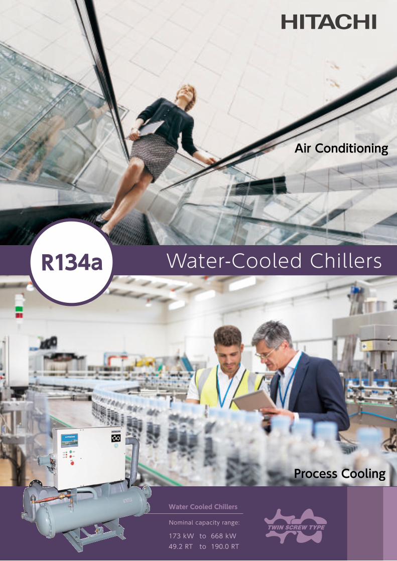
Water-Cooled Chillers Water Cooled Chillers Nominal capacity range: 173 kW 49.2 RT 668 kW 190.0 RT to to Air Conditioning Process Cooling R134a
Transcript of Water-Cooled Chillers - Johnson Controls Hitachi · PDF fileWater-Cooled Chillers Water Cooled...
Printed in Japan (H) HR-E621P Oct. 2015
Water-Cooled Chillers
Water Cooled Chillers
Nominal capacity range:
173 kW
49.2 RT
668 kW
190.0 RT
to
to
Air Conditioning
Process Cooling
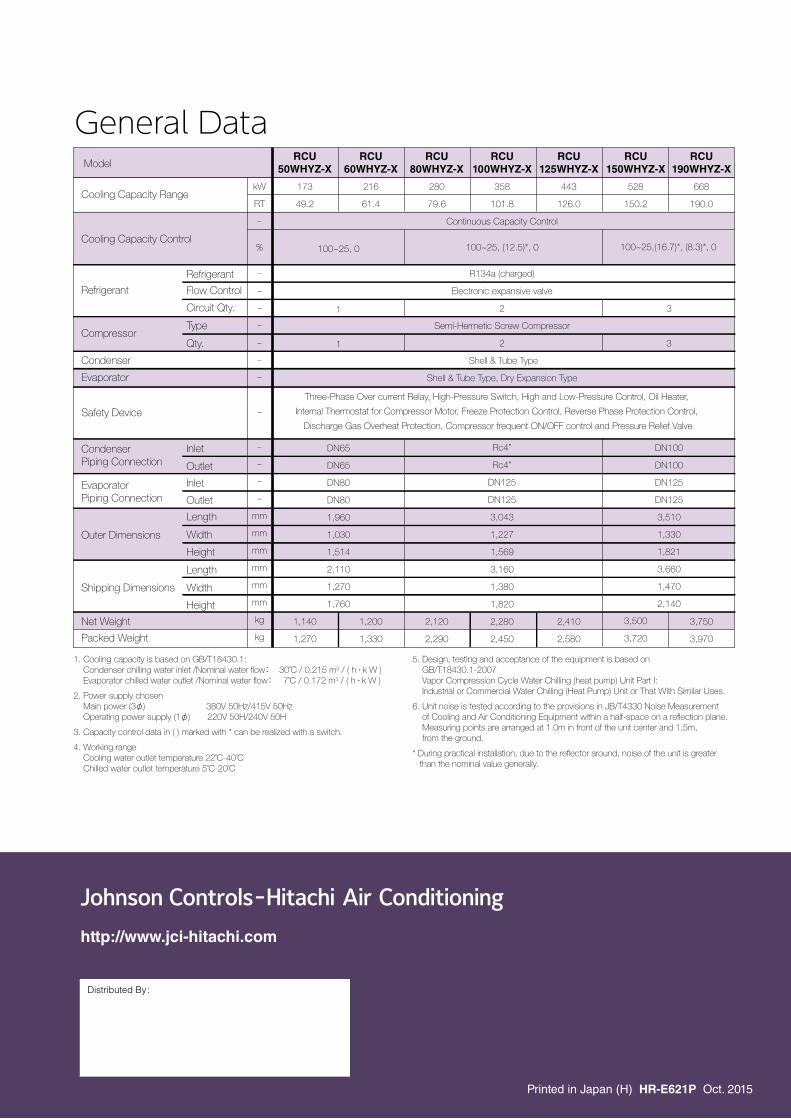
General DataModel
Cooling Capacity Range
Cooling Capacity Control
Refrigerant
Refrigerant
kW
RT
-
%
-
-
-
-
-
-
-
-
-
-
-
-
mm
mm
mm
mm
mm
mm
kg
kg
173
49.2
1,140
1,270
216
61.4
1,200
1,330
280
79.6
2,120
2,290
358
101.8
100~25, (12.5)*, 0
443
126.0
2,410
2,580
528
150.2
668
190.0
3,750
3,970
100~25, 0
1
1
DN65
DN65
DN80
DN80
1,960
1,030
1,514
2,110
1,270
1,760
3
3
DN100
DN100
DN125
DN125
3,510
1,330
1,821
3,660
1,470
2,140
3,500
3,720
Inlet
Outlet
Inlet
Outlet
Length
Width
Height
Length
Width
Height
Flow Control
Circuit Qty.
CompressorType
Qty.
Condenser
Evaporator
Safety Device
Condenser Piping Connection
Evaporator Piping Connection
Outer Dimensions
Shipping Dimensions
Net Weight
Packed Weight
RCU50WHYZ-X
RCU60WHYZ-X
RCU80WHYZ-X
RCU100WHYZ-X
RCU125WHYZ-X
RCU150WHYZ-X
RCU190WHYZ-X
Continuous Capacity Control
R134a (charged)
Electronic expansive valve
2
Semi-Hermetic Screw Compressor
2
Shell & Tube Type
Shell & Tube Type, Dry Expansion Type
Rc4”
Rc4”
DN125
DN125
3,043
1,227
1,569
3,160
1,380
1,820
2,280
2,450
1. Cooling capacity is based on GB/T18430.1: Condenser chilling water inlet /Nominal water flow: 30˚C / 0.215 m3 / ( h . k W ) Evaporator chilled water outlet /Nominal water flow: 7˚C / 0.172 m3 / ( h . k W )
2. Power supply chosen Main power (3φ) 380V 50Hz/415V 50Hz Operating power supply (1φ) 220V 50H/240V 50H
3. Capacity control data in ( ) marked with * can be realized with a switch.
4. Working range Cooling water outlet temperature 22˚C-40˚C Chilled water outlet temperature 5˚C-20˚C
5. Design, testing and acceptance of the equipment is based on GB/T18430.1-2007 Vapor Compression Cycle Water Chilling (heat pump) Unit Part I: Industrial or Commercial Water Chilling (Heat Pump) Unit or That With Similar Uses.
6. Unit noise is tested according to the provisions in JB/T4330 Noise Measurement of Cooling and Air Conditioning Equipment within a half-space on a reflection plane. Measuring points are arranged at 1.0m in front of the unit center and 1.5m, from the ground.
* During practical installation, due to the reflector around, noise of the unit is greater than the nominal value generally.
R134a
100~25,(16.7)*, (8.3)*, 0
Three-Phase Over current Relay, High-Pressure Switch, High and Low-Pressure Control, Oil Heater,
Internal Thermostat for Compressor Motor, Freeze Protection Control, Reverse Phase Protection Control,
Discharge Gas Overheat Protection, Compressor frequent ON/OFF control and Pressure Relief Valve
http://www.jci-hitachi.com
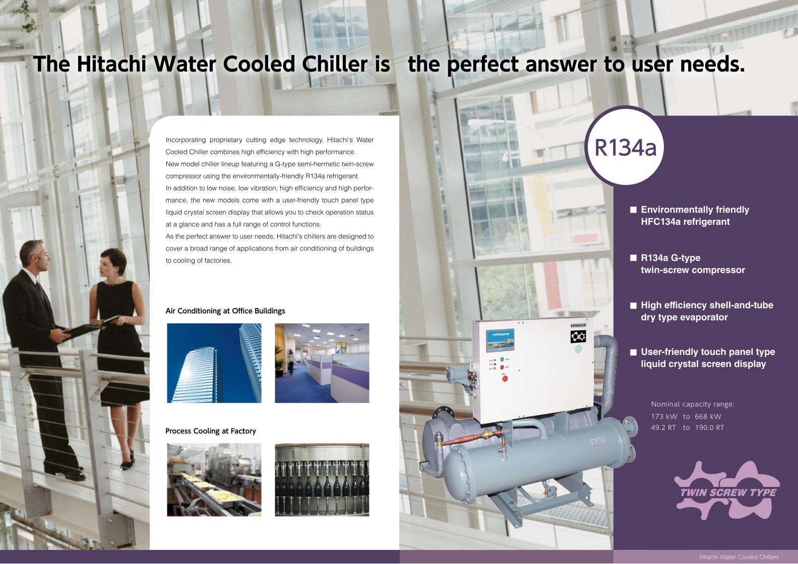
Incorporating proprietary cutting edge technology, Hitachi's Water
Cooled Chiller combines high efficiency with high performance.
New model chiller lineup featuring a G-type semi-hermetic twin-screw
compressor using the environmentally-friendly R134a refrigerant.
In addition to low noise, low vibration, high efficiency and high perfor-
mance, the new models come with a user-friendly touch panel type
liquid crystal screen display that allows you to check operation status
at a glance and has a full range of control functions.
As the perfect answer to user needs, Hitachi's chillers are designed to
cover a broad range of applications from air conditioning of buildings
to cooling of factories.
Air Conditioning at Of�ce Buildings
Process Cooling at Factory
R134a
Hitachi Water Cooled Chillers
Environmentally friendly HFC134a refrigerant
R134a G-type twin-screw compressor
High efficiency shell-and-tube dry type evaporator
User-friendly touch panel type liquid crystal screen display
Nominal capacity range:
173 kW
49.2 RT
668 kW
190.0 RT
to
to
The Hitachi Water Cooled Chiller is the perfect answer to user needs.
3 4
Hitachi Water Cooled Chillers
Accurate
Green
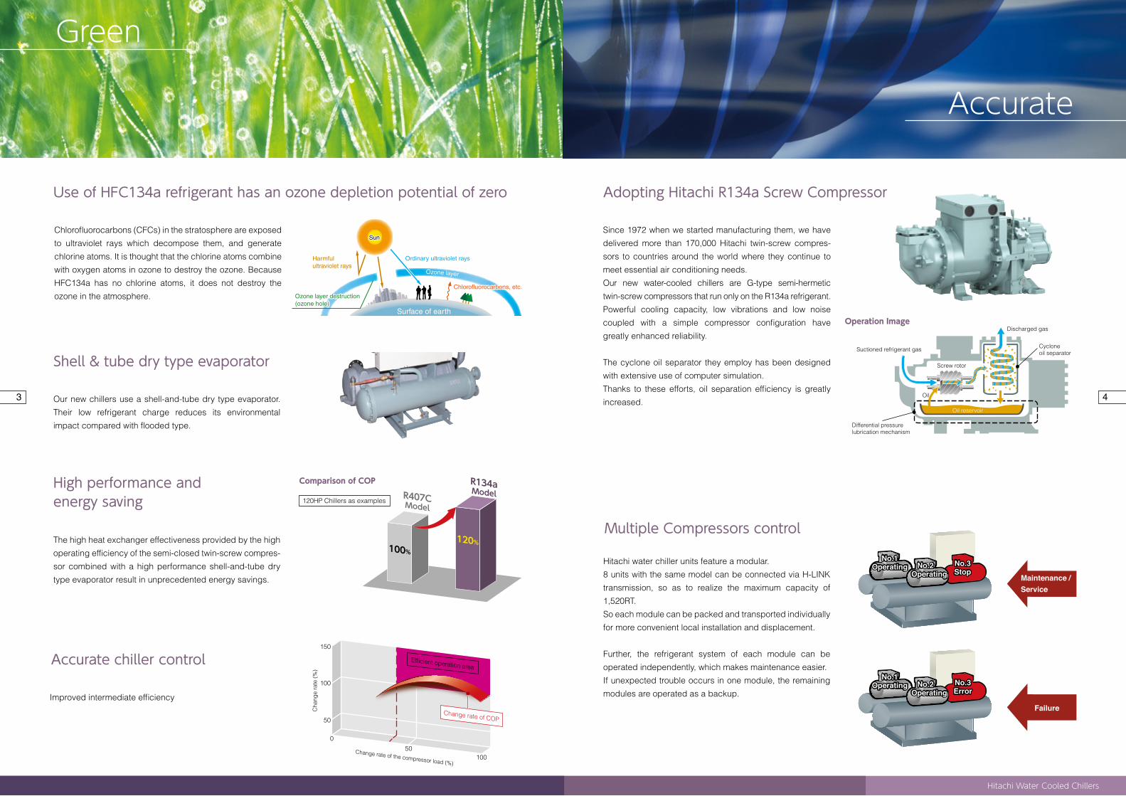
Adopting Hitachi R134a Screw CompressorUse of HFC134a refrigerant has an ozone depletion potential of zero
High performance and energy saving
Accurate chiller control
Since 1972 when we started manufacturing them, we have
delivered more than 170,000 Hitachi twin-screw compres-
sors to countries around the world where they continue to
meet essential air conditioning needs.
Our new water-cooled chillers are G-type semi-hermetic
twin-screw compressors that run only on the R134a refrigerant.
Powerful cooling capacity, low vibrations and low noise
coupled with a simple compressor configuration have
greatly enhanced reliability.
The cyclone oil separator they employ has been designed
with extensive use of computer simulation.
Thanks to these efforts, oil separation efficiency is greatly
increased.
Chlorofluorocarbons (CFCs) in the stratosphere are exposed
to ultraviolet rays which decompose them, and generate
chlorine atoms. It is thought that the chlorine atoms combine
with oxygen atoms in ozone to destroy the ozone. Because
HFC134a has no chlorine atoms, it does not destroy the
ozone in the atmosphere.
The high heat exchanger effectiveness provided by the high
operating efficiency of the semi-closed twin-screw compres-
sor combined with a high performance shell-and-tube dry
type evaporator result in unprecedented energy savings.
Our new chillers use a shell-and-tube dry type evaporator.
Their low refrigerant charge reduces its environmental
impact compared with flooded type.
Suctioned refrigerant gas
Discharged gas
Differential pressure lubrication mechanism
Efficient operation area
Change rate of the compressor load (%)
Change rate of COP
0
50
50
100
100
150
Cha
nge
rate
(%)
Comparison of COP
R407CModel
R134aModel
120HP Chillers as examples
Shell & tube dry type evaporator
Operation Image
Screw rotor
Oil
Oil reservoir
Cyclone oil separator
Multiple Compressors control
Sun
Ordinary ultraviolet raysHarmful ultraviolet rays
Ozone layer destruction (ozone hole)
Ozone layer
Surface of earth
Chlorofluorocarbons, etc.
Sun
Ozone layer destruction (ozone hole)
Chlorofluorocarbons, etc.
Improved intermediate efficiency
Hitachi water chiller units feature a modular.
8 units with the same model can be connected via H-LINK
transmission, so as to realize the maximum capacity of
1,520RT.
So each module can be packed and transported individually
for more convenient local installation and displacement.
Further, the refrigerant system of each module can be
operated independently, which makes maintenance easier.
If unexpected trouble occurs in one module, the remaining
modules are operated as a backup. No.3
Error
No.2 Operating
No.1Operating No.3
StopNo.3Stop
No.2 Operating
No.1Operating
No.2 Operating
No.1Operating No.3
ErrorNo.3Error
No.2 Operating
No.1Operating
Maintenance / Service
Failure
120%100%
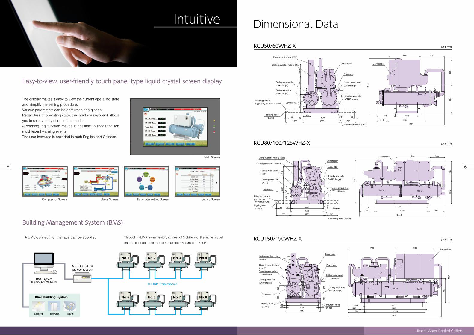
Dimensional Data
RCU150/190WHZ-X
RCU80/100/125WHZ-X
RCU50/60WHZ-X
Intuitive
A BMS-connecting interface can be supplied.
Building Management System (BMS)
BMS System(Supplied by BMS Maker)
MODOBUS RTUprotocol (option)
Other Building System
Lighting Elevator Alarm
Easy-to-view, user-friendly touch panel type liquid crystal screen display
The display makes it easy to view the current operating state and simplify the setting procedure.Various parameters can be confirmed at a glance. Regardless of operating state, the interface keyboard allows you to set a variety of operation modes.A warning log function makes it possible to recall the ten most recent warning events.The user interface is provided in both English and Chinese.
No.1 No.2 No.3 No.4
No.5 No.6 No.7 No.8
H-LINK Transmission
Through H-LINK transmission, at most of 8 chillers of the same model
can be connected to realize a maximum volume of 1520RT.
5 6
Hitachi Water Cooled Chillers
Main power line hole (φ78)
Control power line hole (φ32.5)Compressor Electrical box
Electrical box
Electrical box
Evaporator
Chilled water outlet
(DN80 flange)
Cooling water inlet
(DN80 flange)
Cooling water outlet
(DN65 flange)
Cooling water inlet
(DN65 flange)
Condenser
Mounting holes (4-φ26)
Compressor
Evaporator
Chilled water outlet
(DN125 flange)
Cooling water inlet
(DN125 flange)
Mounting holes (4-φ26)
Lifting support x 4
(supplied by the manufacturer)
Rigging holes
(4-φ40)
Main power line hole (φ112.5)
Control power line hole (φ32.5)
Cooling water outlet
(RC4”)
Cooling water inlet
(RC4”)
Condenser
Lifting support x 4
(supplied by the manufacturer)
Rigging holes
(4-φ40)
Compressor
Evaporator
Chilled water outlet
(DN125 flange)
Cooling water inlet
(DN125 flange)
Mounting holes
(4-φ26)
Main power line hole
(φ64.5)
Control power line hole
(φ32.5)
Cooling water outlet
(DN100 flange)
Cooling water inlet
(DN100 flange)
Condenser
Rigging holes
(4-φ40)
360
492
350
280
250
297
500
50225
970
10301960
1110
900 703
728
764
1514
318
812
1569
762
805
391
2195
1821
14301796
89650
828
1
280
365
3510
2288
2513
2200598442
614
264881 1168
1235
1330
1230 500
2163
30431256
1205
114550 50284
400
372
17010
7631
2
30
500 500
489
473
500
5030
(unit: mm)
(unit: mm)
(unit: mm)
Main Screen
Setting ScreenParameter setting ScreenStatus ScreenCompressor Screen
Surface of earth
Printed in Japan (H) HR-E621P Oct. 2015
Water-Cooled Chillers
Water Cooled Chillers
Nominal capacity range:
173 kW
49.2 RT
668 kW
190.0 RT
to
to
Air Conditioning
Process Cooling
General DataModel
Cooling Capacity Range
Cooling Capacity Control
Refrigerant
Refrigerant
kW
RT
-
%
-
-
-
-
-
-
-
-
-
-
-
-
mm
mm
mm
mm
mm
mm
kg
kg
173
49.2
1,140
1,270
216
61.4
1,200
1,330
280
79.6
2,120
2,290
358
101.8
100~25, (12.5)*, 0
443
126.0
2,410
2,580
528
150.2
668
190.0
3,750
3,970
100~25, 0
1
1
DN65
DN65
DN80
DN80
1,960
1,030
1,514
2,110
1,270
1,760
3
3
DN100
DN100
DN125
DN125
3,510
1,330
1,821
3,660
1,470
2,140
3,500
3,720
Inlet
Outlet
Inlet
Outlet
Length
Width
Height
Length
Width
Height
Flow Control
Circuit Qty.
CompressorType
Qty.
Condenser
Evaporator
Safety Device
Condenser Piping Connection
Evaporator Piping Connection
Outer Dimensions
Shipping Dimensions
Net Weight
Packed Weight
RCU50WHYZ-X
RCU60WHYZ-X
RCU80WHYZ-X
RCU100WHYZ-X
RCU125WHYZ-X
RCU150WHYZ-X
RCU190WHYZ-X
Continuous Capacity Control
R134a (charged)
Electronic expansive valve
2
Semi-Hermetic Screw Compressor
2
Shell & Tube Type
Shell & Tube Type, Dry Expansion Type
Rc4”
Rc4”
DN125
DN125
3,043
1,227
1,569
3,160
1,380
1,820
2,280
2,450
1. Cooling capacity is based on GB/T18430.1: Condenser chilling water inlet /Nominal water flow: 30˚C / 0.215 m3 / ( h . k W ) Evaporator chilled water outlet /Nominal water flow: 7˚C / 0.172 m3 / ( h . k W )
2. Power supply chosen Main power (3φ) 380V 50Hz/415V 50Hz Operating power supply (1φ) 220V 50H/240V 50H
3. Capacity control data in ( ) marked with * can be realized with a switch.
4. Working range Cooling water outlet temperature 22˚C-40˚C Chilled water outlet temperature 5˚C-20˚C
5. Design, testing and acceptance of the equipment is based on GB/T18430.1-2007 Vapor Compression Cycle Water Chilling (heat pump) Unit Part I: Industrial or Commercial Water Chilling (Heat Pump) Unit or That With Similar Uses.
6. Unit noise is tested according to the provisions in JB/T4330 Noise Measurement of Cooling and Air Conditioning Equipment within a half-space on a reflection plane. Measuring points are arranged at 1.0m in front of the unit center and 1.5m, from the ground.
* During practical installation, due to the reflector around, noise of the unit is greater than the nominal value generally.
R134a
100~25,(16.7)*, (8.3)*, 0
Three-Phase Over current Relay, High-Pressure Switch, High and Low-Pressure Control, Oil Heater,
Internal Thermostat for Compressor Motor, Freeze Protection Control, Reverse Phase Protection Control,
Discharge Gas Overheat Protection, Compressor frequent ON/OFF control and Pressure Relief Valve
http://www.jci-hitachi.com