Air-Cooled Liquid Chillers¾یش... · Air-Cooled Liquid Chillers 30XA “A” 252-1702 Nominal...
15
Air-Cooled Liquid Chillers www.eurovent-certification.com www.certiflash.com 30XA “A” 252-1702 Nominal cooling capacity 267-1682 kW Unit with options 279 and 23A 50 Hz The Aquaforce liquid chillers are the premium solution for industrial and commercial applications where installers , consultants and building owners require optimal perfor - mances and maximum quality. The units are designed to operate up to 55°C outside air temperature. The Aquaforce liquid chillers are designed to meet current and future requirements in terms of energy efficiency and operating sound levels. They use the best technologies available today: - Twin-rotor screw compressors with a variable capacity valve. - Single refrigerant R-134a. - Low-noise generation IV Flying Bird fans made of composite material. - Aluminium micro-channel heat exchangers (MCHE) - Pro-Dialog+ control system. To meet to all environmental and economic requirements , the Aquaforce is available in two versions: One offers an extremely low noise level while at the same time boasting superior energy efficiency. The other offers unequalled energy efficiency to satisfy the most stringent demands of building owners wanting to reduce operating costs to the minimum. This version is also recommended for applications in geographical zones where the air temperature is very high. Features and advantages Very economical operation ■ Exceptionally high full load and part load energy efficiency: - Eurovent energy efficiency class A and B (unit with high-efficiency option 119). - Standardised Eurovent values in accordance with EN 14511-3:2011: EER up to 3.3 and ESEER up to 4.2. - New twin-rotor screw compressor equipped with a high-efficiency motor and a variable capacity valve that permits exact matching of the cooling capacity to the load. - All aluminium condenser with high-efficiency micro- channels. - Flooded shell-and-tube evaporator to increase the heat exchange efficiency. - Electronic expansion device permitting operation at a lower condensing pressure and improved utilisation of the evaporator heat exchange surface (superheat control). - Economizer system with electronic expansion device for increased cooling capacity
Transcript of Air-Cooled Liquid Chillers¾یش... · Air-Cooled Liquid Chillers 30XA “A” 252-1702 Nominal...

Air-Cooled Liquid Chillers
www.eurovent-certification.com
www.certiflash.com
30XA “A” 252-1702
Nominal cooling capacity 267-1682 kW
Unit with options 279 and 23A
50 HzThe Aquaforce liquid chillers are the premium solution forindustrial and commercial applications where installers,consultants and building owners require optimal perfor-mances and maximum quality. The units are designed tooperate up to 55°C outside air temperature.
The Aquaforce liquid chillers are designed to meet currentand future requirements in terms of energy efficiency andoperating sound levels. They use the best technologiesavailable today:- Twin-rotor screw compressors with a variable capacity
valve.- Single refrigerant R-134a.- Low-noise generation IV Flying Bird fans made of
composite material.- Aluminium micro-channel heat exchangers (MCHE)- Pro-Dialog+ control system.
To meet to all environmental and economic requirements,the Aquaforce is available in two versions:
One offers an extremely low noise level while at the sametime boasting superior energy efficiency.
The other offers unequalled energy efficiency to satisfythe most stringent demands of building owners wanting toreduce operating costs to the minimum. This version isalso recommended for applications in geographical zoneswhere the air temperature is very high.
Features and advantages
Very economical operation■ Exceptionally high full load and part load energy efficiency:
- Eurovent energy efficiency class A and B (unit withhigh-efficiency option 119).
- Standardised Eurovent values in accordance with EN14511-3:2011: EER up to 3.3 and ESEER up to 4.2.
- New twin-rotor screw compressor equipped with ahigh-efficiency motor and a variable capacity valve thatpermits exact matching of the cooling capacity to theload.
- All aluminium condenser with high-efficiency micro-channels.
- Flooded shell-and-tube evaporator to increase the heatexchange efficiency.
- Electronic expansion device permitting operation at alower condensing pressure and improved utilisation of theevaporator heat exchange surface (superheat control).
- Economizer system with electronic expansion device forincreased cooling capacity

Low operating sound levels■ Compressors
- Discharge dampers integrated in the oil separator(Carrier patent).
- Silencer on the economiser return line.- Acoustic compressor and oil separator enclosure
reducing radiated noise (option)■ Condenser section
- Condenser coils in V-shape with an open angle, allowingquieter air flow across the coil
- Low-noise 4th generation Flying Bird fans, made of acomposite material (Carrier patent) are now even quieterand do not generate intrusive low-frequency noise
- Rigid fan mounting preventing start-up noise (Carrierpatent)
Easy and fast installation■ Integrated hydronic module (option)
- Centrifugal low or high-pressure water pump (as required),based on the pressure loss of the hydronic installation
- Single or dual pump (as required) with operating timebalancing and automatic changeover to the back-up pumpif a fault develops
- Water filter protecting the water pump against circulatingdebris
- High-capacity membrane expansion tank ensurespressurisation of the water circuit
- Thermal insulation and aluminium protection (option)- Pressure sensor to check filter pollution and for direct
numerical display of the water flow rate with an estimate ofthe instantaneous cooling capacity at the control interface
- Water flow control valve■ Simplified electrical connections
- Main disconnect switch with high trip capacity- Transformer to supply the integrated control circuit
(400/24 V)■ Fast commissioning
- Systematic factory operation test before shipment- Quick-test function for step-by-step verification of the
instruments, expansion devices, fans and compressors
Environmental care■ R-134a refrigerant
- Refrigerant of the HFC group with zero ozone depletionpotential
- 30% reduction in the refrigerant charge through the useof micro-channel heat exchangers
■ Leak-tight refrigerant circuit- Reduction of leaks as no capillary tubes and flare connec-
tions are used- Verification of pressure transducers and temperature
sensors without transferring refrigerant charge- Liquid line service valve for simplified maintenance
(option)
Absolute reliability■ Screw compressors
- Industrial-type screw compressors with oversized bearingsand motor cooled by suction gas.
- All compressor components are easily accessible on siteminimising down-time.
- Protection increased by an electronic board.■ Air condenser
- All aluminium micro-channel heat exchanger (MCHE)with high corrosion resistance. The all aluminium designeliminates the formation of galvanic currents betweenaluminium and copper that cause coil corrosion in salineor corrosive environments.
■ Evaporator- Thermal insulation with aluminium sheet finish (option)
for perfect resistance to external aggression (mechanicaland UV protection).
■ Auto-adaptive control- Control algorithm prevents excessive compressor
cycling (Carrier patent)- Automatic compressor unloading in case of abnormally
high condensing pressure. If condenser coil fouling orfan failure occurs, the Aquaforce continues to operate,but at reduced capacity
■ Exceptional endurance tests- Partnerships with specialised laboratories and use of limit
simulation tools (finite element calculation) for the designof critical components.
- Transport simulation test in the laboratory on a vibratingtable. The test is based on a military standard and equi-valent to 4000 km by truck.
- Salt mist corrosion resistance test in the laboratory forincreased corrosion resistance
Pro-Dialog+ controlPro-Dialog+ combines intelligence with operating simplicity.The control constantly monitors all machine parametersand precisely manages the operation of compressors,electronic expansion devices, fans and of the evaporatorwater pump for optimum energy efficiency.
■ Energy management- Internal time schedule clock: controls chiller on/off times
and operation at a second set-point- Set-point reset based on the outside air temperature or
the return water temperature- Master/slave control of two chillers operating in parallel
with operating time equalisation and automatic change-over in case of a unit fault
- Change-over based on the outdoor temperature■ Integrated features
- Night mode: capacity and fan speed limitation forreduced noise level
- With hydronic module: water pressure display and waterflow rate calculation
■ Ease-of-useThe new backlit LCD interface includes a manual controlpotentiometer to ensure legibility under any lightingconditions.- The information is displayed clearly in English, French,
German, Italian and Spanish (for other languages pleaseconsult Carrier).
- The Pro-Dialog+ navigation uses intuitive tree-structuremenus. They are user-friendly and permit quick access tothe principal operating parameters: compressor operation,suction/discharge pressure, compressor operating hours,set point, air temperature, entering/leaving watertemperature

\\MAINMENU\STATUS
CAPB_T 0 %DEM_LIM 100 %SP 4.2 °CCTRL_PNT -28.9 °CEMSTOP dsable
Circuit B Total Capacity
Control interfaces
Pro-Dialog+
Remote management (standard)Aquaforce is equipped with an RS485 serial port that offersmultiple remote control, monitoring and diagnostic possi-bilities. Carrier offers a vast choice of control products,specially designed to control, manage and supervise theoperation of an air conditioning system. Please consultyour Carrier representative for more information.
START/STOP
PRO-DIALOG+
ENTER
Aquaforce also communicates with other building manage-ment systems via optional communication gateways. Aconnection terminal allows remote control of the Aquaforceby wired cable:- Start/stop: opening of this contact will shut down the unit- Dual set-point: closing of this contact activates a second
set-point (example: unoccupied mode)- Demand limit: closing of this contact limits the maximum
chiller capacity to a predefined value- Heat reclaim (option): closing of this contact allows heat
reclaim mode operation- Water pump 1 and 2 control (not available for hydronic
module option 116): these outputs control the contactors■ Pro-Dialog + interface (standard)
The standard interface for 30XA 252 to 1702 units has fivebuttons that permit navigation via intuitive tree-structuremenus. In this way all information is very quickly accessible.
Note: The 30XA 1702 unit has two interfaces.
Pro-Dialog Touch Screen
■ Pro-Dialog Touch Screen interface (option 158)This user interface for 30XA 252 to 1702 units with itstouch screen is very user-friendly. It is a large-format touch-screen, and the information is easily accessible: clear textin the selected language allows monitoring of all operatingparameters. Up to eight screens can be personalised.
Note: The 30XA 1702 unit has two interfaces.
of one or two evaporator water pumps- Water pump on reversal (not available for option 116):
these contacts are used to detect a water pump operationfault and automatically change over to the other pump
- Operation indication: this volt-free contact indicates thatthe chiller is operating (cooling load) or that it is ready tooperate (no cooling load)
- Alert indication: this volt-free contact indicates thenecessity to carry out a maintenance operation or thepresence of a minor fault
- Alarm indication: this volt-free contact indicates thepresence of a major fault that has led to the shut-down ofone or several refrigerant circuits
Remote management (EMM option 156)■ The Energy Management Module offers extended remote
control possibilities:- Room temperature: permits set-point reset based on the
building indoor air temperature (with Carrier thermostat)- Set point reset: ensures reset of the cooling set-point
based on a 4-20 mA or 0-5 V signal- Demand limit: permits limitation of the maximum chiller
power or current based on a 0-10 V signal- Demand limit 1 and 2: closing of these contacts limits the
maximum chiller power or current to two predefinedvalues.
- User safety: this contact can be used for any customersafety loop; opening of the contact generates a specificalarm
- Ice storage end: when ice storage has finished, this inputpermits return to the second set-point (unoccupied mode)
- Time schedule override: closing of this contact cancelsthe time schedule effects
- Out of service: this signal indicates that the chiller iscompletely out of service
- Chiller capacity: this analogue output (0-10 V) gives animmediate indication of the chiller capacity

06T screw compressor
The Carrier 06T screw compressor benefits from Carrier’slong experience in the development of twin-rotor screwcompressors.The compressor is equipped with bearings withoversized rollers, oil pressure lubricated for reliable anddurable operation, even at maximum load.
A variable control valve controlled by the oil pressurepermits infinitely variable cooling capacity. This systemallows optimal adjustment of the compressor coolingcapacity and ensures exceptionally high stability of thechilled water leaving temperature.
Among the other advantages: if a fault occurs e.g. if thecondenser is fouled or at very high outside temperature, thecompressor does not switch off, but continues operationwith a reduced capacity (unloaded mode).
The compressor is equipped with a separate oil separatorthat minimises the amount of oil in circulation in therefrigerant circuit and with its integrated silencerconsiderably reduces discharge gas pulsations for muchquieter operation.
All-aluminium micro-channel heat exchanger (MCHE)
Already utilised in the automobile and aeronautical industriesfor many years, the MCHE micro-channel heat exchangerused in the Aquaforce is entirely made of aluminium. Thisone-piece concept significantly increases its corrosionresistance by eliminating the galvanic currents that arecreated when two different metals (copper and aluminium)come into contact in traditional heat exchangers. Unliketraditional heat exchangers the MCHE heat exchanger canbe used in moderate marine and urban environments(Carrier recommendation).
From an energy efficiency point-of-view the MCHE heatexchanger is approximately 10% more efficient than atraditional coil and allows a 30% reduction in the amountof refrigerant used in the chiller. The low thickness of theMCHE reduces air pressure losses by 50% and makes itsusceptible to very little fouling (e.g. by sand). Cleaning ofthe MCHE heat exchanger is very fast using a high-pressure washer.

Depth x height mm 2253 x 2297Compressors 06T semi-hermetic screw compressors, 50 r/s
Physical data, sizes 252 to 90230XA 252 302 352 402 452 502 602 702 752 802 852 902Air conditioning application as per EN14511-3:2011*- standard unitNominal cooling capacity kW 267 291 318 378 426 473 601 654 691 759 807 875EER kW/kW 3.00 2.96 2.98 3.08 2.89 2.93 3.03 3.11 2.91 2.88 2.98 2.91Eurovent class cooling B B B B C B B A B C B BESEER kW/kW 3.94 4.20 4.20 4.10 4.13 4.09 4.08 4.10 4.00 4.06 4.09 3.81Air conditioning application**- standard unitNominal cooling capacity kW 267 291 319 379 427 475 603 656 693 761 809 878EER kW/kW 3.02 2.98 3.01 3.12 2.92 2.97 3.07 3.15 2.94 2.91 3.01 2.94ESEER kW/kW 4.03 4.30 4.31 4.26 4.30 4.25 4.25 4.25 4.14 4.19 4.25 3.93Air conditioning application as per EN14511-3:2011* - unit with option 119***Nominal cooling capacity kW 273 298 325 391 442 499 612 679 723 785 841 886EER kW/kW 3.13 3.10 3.09 3.21 3.08 3.15 3.13 3.31 3.08 3.10 3.24 3.12Eurovent class cooling A A B A B A A A B A A AESEER kW/kW 3.89 3.96 4.01 3.88 3.93 3.93 3.84 4.07 3.87 3.92 4.03 3.82Air conditioning application** - unit with option 119***Nominal cooling capacity kW 273 298 325 392 443 500 614 681 726 787 844 889EER kW/kW 3.15 3.12 3.12 3.25 3.12 3.19 3.18 3.35 3.12 3.13 3.28 3.15ESEER kW/kW 3.97 4.04 4.10 4.03 4.08 4.08 4.00 4.22 4.01 4.05 4.18 3.94Operating weight****Standard unit + option 119*** kg 3410 3450 3490 4313 4883 4814 5707 5857 6157 6457 6958 7258Unit with options 254/255*** kg 3830 3860 4380 4830 4900 5470 6480 6640 7430 7750 7870 8620Sound levelsStandard unitSound power level† dB(A) 99 99 99 98 101 98 100 98 103 102 100 104Sound pressure level at 10 m†† dB(A) 67 67 67 65 69 65 67 65 70 70 67 71Unit with option 279***Sound power level† dB(A) 89 89 89 92 93 93 95 94 96 96 95 97Sound pressure level at 10 m†† dB(A) 57 57 57 60 61 61 62 61 63 64 63 64
Standard unit + option 257***Sound power level† dB(A) 87 87 87 90 91 91 93 92 94 94 94 95Sound pressure level at 10 m†† dB(A) 55 55 55 58 59 59 60 59 61 61 61 62Standard unit + option 258***Sound power level† dB(A) - - - - 89 89 91 90 91 92 91 93Sound pressure level at 10 m†† dB(A) - - - - 57 56 58 57 59 59 59 60High-efficiency unit with option 119***Sound power level† dB(A) 100 100 100 100 102 100 102 100 104 104 102 105Sound pressure level at 10 m†† dB(A) 68 68 68 68 70 68 69 68 71 71 69 72High-efficiency unit with options 119 + 257***Sound power level† dB(A) 93 93 93 95 95 95 97 96 97 97 97 98Sound pressure level at 10 m†† dB(A) 61 61 61 63 63 63 65 63 64 64 64 65DimensionsLength, standard unit mm 3604 3604 3604 4798 4798 5992 7186 7186 7186 7186 8380 8380Length, unit + opt. 254/255*** mm 3604 3604 4798 4798 4798 5992 7186 7186 8380 8380 8380 9574
Circuit A + BCircuit C + D
1 + 1-
1 + 1-
1 + 1-
1 + 1-
1 + 1-
1 + 1-
1 + 1-
1 + 1-
1 + 1-
1 + 1-
1 + 1-
1 + 1-
Refrigerant**** R-134aStandard unit and unit with option 119***Circuit A kg 37 35 35 51 52 59 58 58 65 69 72 69Circuit B kg 39 36 37 37 37 36 59 62 58 65 63 76Circuit C + D kg - - - - - - - - - - - -Unit with options 254/255***Circuit A kg 60 64 70 85 85 102 102 100 129 112 130 129Circuit B kg 64 64 56 56 56 56 88 95 88 95 95 103Circuit C + D kg - - - - - - - - - - - -Capacity control Pro-Dialog, electronic expansion valve (EXV), minimum capacity 15%Condensers All-aluminium micro-channel heat exchangerFans Axial Flying Bird 4, rotating shroud - speed standard unit + unit with options 254/255 = 11.7 r/s; speed unit with option 119 = 15.7 r/sQty. standard unit + with opt. 119*** 6 6 6 8 8 9 11 12 12 12 14 14Qty. unit + options 254/255*** 6 6 7 8 8 9 11 12 13 13 14 15Total air flowStd. unit + with options 254/255 l/s 20500 20500 20500 27333 27333 30750 37583 41000 41000 41000 47833 47833Unit with option 119*** l/s 27083 27083 27083 36111 36111 40625 49653 54167 54167 54167 63194 63194Evaporator Flooded shell-and-tube typeWater content l 58 61 61 66 70 77 79 94 98 119 119 130Without hydronic module Max. water-side pressure 1000 kPa, Victaulic water inlet and outlet connectionsNominal diameter‡ in 5 5 5 5 5 5 5 6 6 6 6 6Actual outside diameter‡ mm 141.3 141.3 141.3 141.3 141.3 141.3 141.3 168.3 168.3 168.3 168.3 168.3With hydronic module (option 116)*** Max. water-side pressure 400 kPa, nom. diameter 4”, actual outside diameter 114.3 mm, Victaulic water inlet + outlet connectionsExpansion tank volume l 50 50 50 50 50 80 - - - - - -Chassis paint colour Colour code: RAL7035
* Eurovent-certified performances in accordance with standard EN14511-3:2011.Cooling mode conditions: evaporator water entering/leaving temperature 12°C/7°C, outside air temperature 35°C. evaporator fouling factor 0 m2 K/W
** Gross performances, not in accordance with EN14511-3:2011. These performances do not take into account the correction for the proportional heating capacity and power input generated by thewater pump to overcome the internal pressure drop in the heat exchanger.Cooling mode conditions: evaporator water entering/leaving temperature 12°C/7°C, outside air temperature 35°C. evaporator fouling factor 0 m2 K/W
*** Options: 119 = high energy efficiency; 254 = traditional Cu/Al coils, 255 = traditional Cu/Al coils without slots, 257 = low noise level, 258 = very low noise leve, 279 = compressor enclosure.**** Weights are guidelines only. The refrigerant charge is also given on the unit nameplate.
† In accordance with ISO 9614-1 and certified by Eurovent†† Average sound pressure level, unit in a free field on a reflective surface
‡ Evporator 1 and 2 connection diameters for sizes 1352 to 1502.Notes:
1 Unit sizes 30XA 1402 to 1702 are supplied in two field-assembled modules.2 Option 119 can be used with options 254 or 255. Contact your Carrier representative for the performances.
10

Physical data, sizes 1002 to 170230XA 1002 1102 1112 1202 1212 1302 1312 1352 1382 1402 1502 1702Air conditioning application as per EN14511-3:2011*- standard unitNominal cooling capacity kW 960 1119 1107 1216 1218 1294 1285 1383 1377 1436 1443 1611EER kW/kW 2.95 3.02 3.04 2.96 3.09 2.87 2.91 2.64 2.77 2.97 2.87 3.00Eurovent class cooling B B B B B C B D C B C BESEER kW/kW 3.82 4.05 3.89 3.93 4.08 3.88 3.61 3.69 3.54 3.95 3.85 3.81Air conditioning application**- standard unitNominal cooling capacity kW 962 1122 1109 1219 1220 1298 1288 1387 1380 1441 1447 1616EER kW/kW 2.98 3.06 3.06 2.99 3.11 2.91 2.93 2.67 2.79 3.00 2.91 3.04ESEER kW/kW 3.93 4.20 3.97 4.08 4.17 4.03 3.69 3.82 3.63 4.10 4.00 3.97Air conditioning application as per EN14511-3:2011* - unit with option 119***Nominal cooling capacity kW 976 1147 1144 1235 1247 1317 1326 1437 1433 1480 1525 1682EER kW/kW 3.09 3.24 3.27 3.09 3.23 3.09 3.16 3.09 3.06 3.20 3.19 3.22Eurovent class cooling B A A B A B A B B A A AESEER kW/kW 3.74 4.08 4.00 3.93 4.10 4.00 3.89 4.03 3.91 3.98 3.97 3.87Air conditioning application** - unit with option 119***Nominal cooling capacity kW 978 1151 1146 1238 1249 1321 1329 1442 1436 1485 1530 1688EER kW/kW 3.13 3.28 3.30 3.13 3.25 3.13 3.19 3.13 3.09 3.24 3.23 3.27ESEER kW/kW 3.85 4.24 4.08 4.01 4.19 4.17 4.00 4.18 4.02 4.13 4.12 4.05Operating weight****Standard unit + option 119*** kg 7836 9590 9410 10020 9570 10410 10180 10770 10270 3953/ 7776 3953/ 7926 6958/ 6958Unit with options 254/255*** kg 8870 10890 - 11310 - 11660 - 12060 - 4460/8830 4460/8950 7880/7880Sound levelsStandard unitSound power level† dB(A) 101 102 103 103 102 102 104 104 104 103 104 103Sound pressure level at 10 m†† dB(A) 68 69 70 70 69 69 71 71 71 69 70 69Standard unit + option 279***Sound power level† dB(A) 96 96 97 96 96 96 100 97 97 97 97 97Sound pressure level at 10 m†† dB(A) 63 63 64 63 63 63 67 64 64 64 64 64Standard unit + option 257***Sound power level† dB(A) 94 95 94 95 94 95 99 96 95 96 96 96Sound pressure level at 10 m†† dB(A) 61 61 61 61 61 61 66 63 62 62 62 62Standard unit + option 258***Sound power level† dB(A) 92 92 93 - 93 92 - 93 94 93 93 93Sound pressure level at 10 m†† dB(A) 59 59 60 - 60 59 - 60 61 60 60 60High-efficiency unit with option 119***Sound power level† dB(A) 103 104 104 105 103 104 105 105 105 105 105 105Sound pressure level at 10 m†† dB(A) 70 71 71 72 70 71 72 72 72 72 72 71High-efficiency unit with options 119 + 257***Sound power level† dB(A) 98 99 98 99 98 99 101 99 99 100 100 100Sound pressure level at 10 m†† dB(A) 65 66 65 66 65 66 68 66 65 67 67 66DimensionsLength, standard unit mm 9574 11962 11962 11962 11962 11962 11962 11962 11962 9574/4798 9574/4798 8380/8380Length, unit + opt. 254/255*** mm 9574 11962 - 11962 - 11962 - 11962 - 9574/4798 9574/4798 8380/8380Depth x height mm 2253 x 2297Compressors 06T semi-hermetic screw compressors, 50 r/sCircuit A + B 1 + 1 1 + 1 1 + 1 1 + 1 1 + 1 1 + 1 1 + 1 1 + 1 1 + 1 1 + 1 1 + 1 1 + 1Circuit C + D - 1 + 0 - 1 + 0 - 1 + 0 - 1 + 0 - 1 + 0 1 + 0 1 + 1Refrigerant**** R-134aStandard unit and unit with option 119***Circuit A/B kg 75/79 64/52 80/116 69/52 80/124 70/59 110/116 83/69 116/124 84/78 85/88 72/63Circuit C/D kg - 80/- - 80/- - 80/- - 81/- - 80/- 80/- 72/63Unit with options 254/255***Circuit A/B kg 140/129 102/92 - 112/92 - 112/92 - 112/98 - 140/103 140/129 130/95Circuit C/D kg - 135/- - 135/- - 135/- - 122/- - 135/- 135/- 130/95Capacity control Pro-Dialog, electronic expansion valve (EXV), minimum capacity 15%Minimum capacity % 15 10 8 10 8 10 8 10 8 10 10 8Condensers All-aluminium micro-channel heat exchangerFans Axial Flying Bird 4, rotating shroud - speed standard unit + unit with options 254/255 = 11.7 r/s; speed unit with option 119 = 15.7 r/sQty. standard unit + opt. 119*** 16 19 19 20 20 20 20 20 20 24 24 28Qty. option 254*** 16 19 - 20 - 20 - 20 - 24 24 28Total air flowStd. unit + with options254/255
l/s 54667 64917 64917 68333 68333 68333 68333 68333 68333 82000 82000 95667
Unit with option 119*** l/s 72222 85764 85764 90278 90278 90278 90278 90278 90278 108333 108333 126389Evaporator Flooded shell-and-tube typeWater content l 140 168 164 182 174 203 180 224 180 230 240 240Without hydronic module Max. water-side pressure 1000 kPa, Victaulic water inlet and outlet connectionsNominal diameter‡ in 8 6 6 6 6 6 6 8/6 6 8/6 8/6 6Actual outside diameter‡ mm 219.1 168.3 168.3 168.3 168.3 168.3 168.3 219.1/ 168.3 168.3 219.1/ 168.3 219.1/ 168.3 168.3Chassis paint colour Colour code: RAL7035
* Eurovent-certified performances in accordance with standard EN14511-3:2011.Cooling mode conditions: evaporator water entering/leaving temperature 12°C/7°C, outside air temperature 35°C. evaporator fouling factor 0 m2 K/W
** Gross performances, not in accordance with EN14511-3:2011. These performances do not take into account the correction for the proportional heating capacity and power input generated by thewater pump to overcome the internal pressure drop in the heat exchanger.Cooling mode conditions: evaporator water entering/leaving temperature 12°C/7°C, outside air temperature 35°C. evaporator fouling factor 0 m2 K/W
*** Options: 119 = high energy efficiency; 254 = traditional Cu/Al coils, 255 = traditional Cu/Al coils without slots, 257 = low noise level, 258 = very low noise leve, 279 = compressor enclosure.**** Weights are guidelines only. The refrigerant charge is also given on the unit nameplate.
† In accordance with ISO 9614-1 and certified by Eurovent†† Average sound pressure level, unit in a free field on a reflective surface
‡ Evporator 1 and 2 connection diameters for sizes 1352 to 1502.Notes:
1 Unit sizes 30XA 1402 to 1702 are supplied in two field-assembled modules.2 Option 119 can be used with options 254 or 255. Contact your Carrier representative for the performances.3 Sizes 1112, 1212, 1312 and 1382 are not available with option 255

Electrical data, sizes 252 to 902Standard unit or with option 8130XA 252 302 352 402 452 502 602 702 752 802 852 902Power circuitNominal power supply V-ph-Hz 400-3-50 ± 10%
Control circuit 24 V via internal transformerMaximum start-up current*Circuit 1** A 269 269 287 402 505 505 574 606 773 803 805 893Circuit 2** A - - - - - - - - - - - -Option 81 A - - - - - - - - - - - -
Nominal start-up current***Circuit 1** A 245 245 262 378 480 480 536 562 735 759 761 845Circuit 2** A - - - - - - - - - - - -Option 81 A - - - - - - - - - - - -
Cosine Phi (maximum)**** 0.88 0.88 0.88 0.88 0.88 0.88 0.88 0.88 0.86 0.86 0.87 0.86Cosine Phi (nominal)† 0.85 0.85 0.84 0.84 0.85 0.85 0.85 0.85 0.83 0.84 0.84 0.85
Maximum power input‡Circuit 1** kW 121 131 141 165 185 204 247 267 293 312 343 359Circuit 2** kW - - - - - - - - - - - -Option 81 kW - - - - - - - - - - - -
Nominal unit current draw†Circuit 1** A 151 167 184 210 242 268 325 352 408 433 453 508Circuit 2** A - - - - - - - - - - - -Option 81 A - - - - - - - - - - - -
Maximum unit current draw (Un)‡Circuit 1** A 198 215 233 270 303 335 404 436 492 522 572 611Circuit 2** A - - - - - - - - - - - -Option 81 A - - - - - - - - - - - -
Maximum unit current draw (Un – 10%)****Circuit 1** A 208 232 251 290 326 360 435 469 529 561 615 657Circuit 2** A - - - - - - - - - - - -Option 81 A - - - - - - - - - - - -
Unit with option 119 or with option 119 and option 8130XA 252 302 352 402 452 502 602 702 752 802 852 902Power circuitNominal power supply V-ph-Hz 400-3-50 ± 10%
Control circuit 24 V via internal transformerMaximum start-up current*Circuit 1** A 274 274 292 407 510 510 583 616 782 812 815 905Circuit 2** A - - - - - - - - - - - -Option 81 A - - - - - - - - - - - -
Nominal start-up current***Circuit 1** A 246 246 261 379 479 479 535 561 734 757 760 845Circuit 2** A - - - - - - - - - - - -Option 81 A - - - - - - - - - - - -
Cosine Phi (maximum)**** 0.88 0.87 0.87 0.88 0.88 0.88 0.88 0.88 0.86 0.86 0.86 0.85Cosine Phi (nominal)† 0.84 0.84 0.83 0.83 0.84 0.84 0.84 0.84 0.83 0.83 0.83 0.84
Maximum power input‡Circuit 1** kW 126 136 147 172 192 212 257 278 304 323 356 372Circuit 2** kW - - - - - - - - - - - -Option 81 kW - - - - - - - - - - - -
Nominal unit current draw†Circuit 1** A 151 167 182 210 239 267 324 349 409 430 446 511Circuit 2** A - - - - - - - - - - - -Option 81 A - - - - - - - - - - - -
Maximum unit current draw (Un)‡Circuit 1** A 208 226 243 284 316 350 423 457 512 542 596 635Circuit 2** A - - - - - - - - - - - -Option 81 A - - - - - - - - - - - -
Maximum unit current draw (Un – 10%)****Circuit 1** A 219 243 262 305 340 376 455 491 551 583 640 683Circuit 2** A - - - - - - - - - - - -Option 81 A - - - - - - - - - - - -
* Instantaneous start-up current (operating current of the smallest compressor + fan current + locked rotor current in star connection of the largest compressor).Values obtained at operation withmaximum unit power input.
** 30XA 1102, 1202, 1302, 1352 and 1402 to 1702 units: circuit 1 supplies circuits A and B, circuit 2 supplies circuits C and D. 30XA 1112, 1212, 1312 and 1382 units: circuit 1 supplies circuit A,circuit 2 supplies circuit B.
*** Instantaneous start-up current (operating current of the smallest compressor + fan current + locked rotor current in star connection of the largest compressor).Values obtained at standardEurovent unit operating conditions: air 35°C, water 12/7°C.
**** Values obtained at operation with maximum unit power input.† Values obtained at standard Eurovent unit operating conditions: air 35°C, water 12/7°C‡ Values obtained at operation with maximum unit power input. Values given on the unit name plate
Notes:1. Motor and fan electrical data if the unit operates at Eurovent conditions (motor ambient temperature 50°C): 1.9 A for standard unit; 3.6 A for unit with option 119
Start-up current: 8.4 A for standard unit; 20 A for unit with option 119Power input: 760 W for standard unit; 1650 W for unit with option 119
2. Unit sizes 30XA 1102 to 1702 have two power connection points.

Electrical data, sizes 1002 to 1702Standard unit or with option 8130XA 1002 1102 1112 1202 1212 1302 1312 1352 1382 1402 1502 1702Power circuitNominal power supply V-ph-Hz 400-3-50 ± 10%
Control circuit 24 V via internal transformerMaximum start-up current**Circuit 1** A 941 574 587 773 587 803 772 891 772 893 941 805Circuit 2** A - 587 772 587 772 587 772 587 772 587 587 805Option 81 A - 991 1085 1079 1131 1155 1198 1242 1228 1248 1294 -
Nominal start-up current***Circuit 1** A 865 536 587 735 587 759 772 859 772 845 865 761Circuit 2** A - 587 772 587 772 587 772 587 772 587 587 761Option 81 A - 909 1023 993 1039 1036 1103 1156 1118 1125 1143 -
Cosine Phi (maximum)**** 0.87 0.87 0.86 0.87 0.87 0.87 0.87 0.86 0.87 0.86 0.87 0.87Cosine Phi (nominal)† 0.85 0.84 0.85 0.86 0.86 0.84 0.87 0.85 0.87 0.86 0.85 0.85
Maximum power input‡Circuit 1** kW 420 247 182 293 211 342 258 388 278 390 420 343Circuit 2** kW - 210 279 210 302 210 278 209 299 210 210 343Option 81 kW - 457 400 503 512 552 531 597 571 600 630 -
Nominal unit current draw†Circuit 1** A 548 322 258 401 274 445 340 560 356 530 556 452Circuit 2** A - 278 358 278 392 278 356 292 387 278 278 452Option 81 A - 600 616 679 666 723 696 852 743 808 834 -
Maximum unit current draw (Un)‡Circuit 1** A 707 404 313 492 359 568 426 655 456 661 707 572Circuit 2** A - 354 459 354 496 354 456 352 491 354 354 572Option 81 A - 758 771 845 855 922 882 1007 947 1015 1061 -
Maximum unit current draw (Un – 10%)****Circuit 1** A 760 435 332 529 381 611 462 705 494 711 760 615Circuit 2** A - 380 497 380 527 380 494 378 522 380 380 615Option 81 A - 815 828 909 908 991 956 1083 1016 1091 1141 -
Unit with option 119 or with option 119 and 8130XA 1002 1102 1112 1202 1212 1302 1312 1352 1382 1402 1502 1702Power circuitNominal power supply V-ph-Hz 400-3-50 ± 10%
Control circuit 24 V via internal transformerMaximum start-up current**Circuit 1** A 954 583 587 782 587 812 772 901 772 905 954 815Circuit 2** A - 587 772 587 772 587 772 587 772 587 587 815Option 81 A - 1010 1093 1099 1139 1175 1208 1265 1238 1275 1321 -
Nominal start-up current***Circuit 1** A 860 535 587 734 587 757 772 846 772 845 860 760Circuit 2** A - 587 772 587 772 587 772 587 772 587 587 760Option 81 A - 907 1031 991 1047 1026 1113 1124 1128 1122 1133 -
Cosine Phi (maximum)**** 0.86 0.88 0.86 0.87 0.87 0.87 0.87 0.86 0.87 0.86 0.86 0.86Cosine Phi (nominal)† 0.84 0.84 0.84 0.84 0.84 0.84 0.85 0.84 0.86 0.84 0.84 0.84
Maximum power input‡Circuit 1** kW 435 257 186 304 216 353 262 400 284 405 435 356Circuit 2** kW - 217 286 217 309 217 284 216 305 217 217 356Option 81 kW - 475 471 522 525 570 544 615 584 622 652 -
Nominal unit current draw†Circuit 1** A 541 323 259 400 275 435 341 529 356 527 546 446Circuit 2** A - 273 360 273 393 273 356 275 386 273 273 446Option 81 A - 596 619 673 668 708 697 804 742 800 820 -
Maximum unit current draw (Un)‡Circuit 1** A 734 423 321 512 367 588 436 678 466 688 734 596Circuit 2** A - 367 470 367 508 367 466 364 501 367 367 596Option 81 A - 790 790 879 875 956 902 1041 967 1056 1102 -
Maximum unit current draw (Un – 10%)****Circuit 1** A 790 455 340 551 389 633 472 729 504 740 790 640Circuit 2** A - 395 508 395 539 395 504 391 532 395 395 640Option 81 A - 850 847 946 928 1028 976 1120 1036 1135 1185 -
* Instantaneous start-up current (operating current of the smallest compressor + fan current + locked rotor current in star connection of the largest compressor).Values obtained at operation withmaximum unit power input.
** 30XA 1102, 1202, 1302, 1352 and 1402 to 1702 units: circuit 1 supplies circuits A and B, circuit 2 supplies circuits C and D. 30XA 1112, 1212, 1312 and 1382 units: circuit 1 supplies circuit A,circuit 2 supplies circuit B.
*** Instantaneous start-up current (operating current of the smallest compressor + fan current + locked rotor current in star connection of the largest compressor).Values obtained at standardEurovent unit operating conditions: air 35°C, water 12/7°C
**** Values obtained at operation with maximum unit power input.† Values obtained at standard Eurovent unit operating conditions: air 35°C, water 12/7°C‡ Values obtained at operation with maximum unit power input. Values given on the unit name plate
Notes:1. Motor and fan electrical data if the unit operates at Eurovent conditions (motor ambient temperature 50°C): 1.9 A for standard unit; 3.6 A for unit with option 119
Start-up current: 8.4 A for standard unit; 20 A for unit with option 119Power input: 760 W for standard unit; 1650 W for unit with option 119
2. Unit sizes 30XA 1102 to 1702 have two power connection points.
Load % Air temperature °C Energy efficiency Operating time %100 35 EER
13
30XA 252 302 352 402 452 502 602 702 752 802 852 902 1002 1102 1112 1202 1212 1302 1312 1352 1382 1402 1502 1702Standard unitIPLV kW/kW 4.41 4.50 4.77 4.73 4.75 4.77 4.54 4.67 4.58 4.55 4.66 4.35 4.39 4.66 4.36 4.54 4.60 4.54 3.95 4.29 3.97 4.57 4.43 4.33
1
2
3
4
2
3
4
1 2 3 4
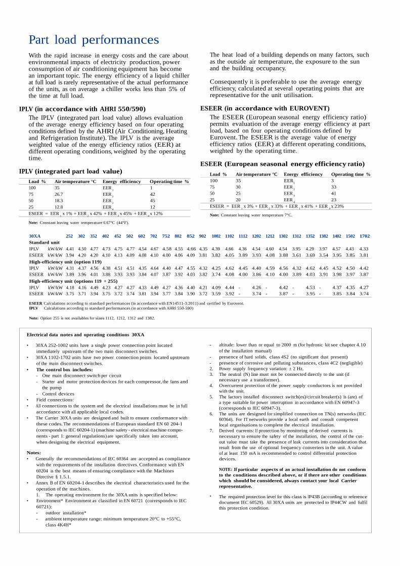
Part load performancesWith the rapid increase in energy costs and the care aboutenvironmental impacts of electricity production, powerconsumption of air conditioning equipment has becomean important topic. The energy efficiency of a liquid chillerat full load is rarely representative of the actual performanceof the units, as on average a chiller works less than 5% ofthe time at full load.
IPLV (in accordance with AHRI 550/590)The IPLV (integrated part load value) allows evaluationof the average energy efficiency based on four operatingconditions defined by the AHRI (Air Conditioning, Heatingand Refrigeration Institute). The IPLV is the averageweighted value of the energy efficiency ratios (EER) atdifferent operating conditions, weighted by the operatingtime.
IPLV (integrated part load value)Load % Air temperature °C Energy efficiency Operating time %100 35 EER 175 26.7 EER 4250 18.3 EER 4525 12.8 EER 12
The heat load of a building depends on many factors, suchas the outside air temperature, the exposure to the sunand the building occupancy.
Consequently it is preferable to use the average energyefficiency, calculated at several operating points that arerepresentative for the unit utilisation.
ESEER (in accordance with EUROVENT)The ESEER (European seasonal energy efficiency ratio)permits evaluation of the average energy efficiency at partload, based on four operating conditions defined byEurovent. The ESEER is the average value of energyefficiency ratios (EER) at different operating conditions,weighted by the operating time.
ESEER (European seasonal energy efficiency ratio)
75 30 EER 3350 25 EER 4125 20 EER 23ESEER = EER x 3% + EER x 33% + EER x 41% + EER x 23%
ESEER = EER x 1% + EER x 42% + EER x 45% + EER x 12%1 2 3 4 Note: Constant leaving water temperature 7°C.
Note: Constant leaving water temperature 6.67°C (44°F).
ESEER kW/kW 3.94 4.20 4.20 4.10 4.13 4.09 4.08 4.10 4.00 4.06 4.09 3.81 3.82 4.05 3.89 3.93 4.08 3.88 3.61 3.69 3.54 3.95 3.85 3.81
High-efficiency unit (option 119)IPLV kW/kW 4.31 4.37 4.56 4.38 4.51 4.51 4.35 4.64 4.40 4.47 4.55 4.32 4.25 4.62 4.45 4.40 4.59 4.56 4.32 4.62 4.45 4.52 4.50 4.42ESEER kW/kW 3.89 3.96 4.01 3.88 3.93 3.93 3.84 4.07 3.87 3.92 4.03 3.82 3.74 4.08 4.00 3.86 4.10 4.00 3.89 4.03 3.91 3.98 3.97 3.87
High-efficiency unit (options 119 + 255)IPLV kW/kW 4.18 4.16 4.49 4.23 4.27 4.27 4.33 4.49 4.27 4.36 4.40 4.21 4.09 4.44 - 4.26 - 4.42 - 4.53 - 4.37 4.35 4.27ESEER kW/kW 3.75 3.71 3.94 3.75 3.72 3.74 3.81 3.94 3.77 3.84 3.90 3.72 3.59 3.92 - 3.74 - 3.87 - 3.95 - 3.85 3.84 3.74
ESEER Calculations according to standard performances (in accordance with EN14511-3:2011) and certified by Eurovent.IPLV Calculations according to standard performances (in accordance with AHRI 550-590)
Note: Option 255 is not availables for sizes 1112, 1212, 1312 and 1382.
Electrical data notes and operating conditions 30XA
• 30XA 252-1002 units have a single power connection point locatedimmediately upstream of the two main disconnect switches.
• 30XA 1102-1702 units have two power connection points located upstreamof the main disconnect switches.
• The control box includes:- One main disconnect switch per circuit- Starter and motor protection devices for each compressor, the fans and
the pump- Control devices
• Field connections:• All connections to the system and the electrical installations must be in full
accordance with all applicable local codes.• The Carrier 30XA units are designed and built to ensure conformance with
these codes. The recommendations of European standard EN 60 204-1(corresponds to IEC 60204-1) (machine safety - electrical machine compo-nents - part 1: general regulations) are specifically taken into account,when designing the electrical equipment.
Notes:• Generally the recommendations of IEC 60364 are accepted as compliance
with the requirements of the installation directives. Conformance with EN60204 is the best means of ensuring compliance with the MachinesDirective § 1.5.1.
• Annex B of EN 60204-1 describes the electrical characteristics used for theoperation of the machines.1. The operating environment for the 30XA units is specified below:
• Environment* Environment as classified in EN 60721 (corresponds to IEC60721):- outdoor installation*- ambient temperature range: minimum temperature 20°C to +55°C,
class 4K4H*
- altitude: lower than or equal to 2000 m (for hydronic kit see chapter 4.10of the installation manual)
- presence of hard solids, class 4S2 (no significant dust present)- presence of corrosive and polluting substances, class 4C2 (negligible)2. Power supply frequency variation: ± 2 Hz.3. The neutral (N) line must not be connected directly to the unit (if
necessary use a transformer).4. Overcurrent protection of the power supply conductors is not provided
with the unit.5. The factory installed disconnect switch(es)/circuit breaker(s) is (are) of
a type suitable for power interruption in accordance with EN 60947-3(corresponds to IEC 60947-3).
6. The units are designed for simplified connection on TN(s) networks (IEC60364). For IT networks provide a local earth and consult competentlocal organisations to complete the electrical installation.
7. Derived currents: If protection by monitoring of derived currents isnecessary to ensure the safety of the installation, the control of the cut-out value must take the presence of leak currents into consideration thatresult from the use of optional frequency converters in the unit. A valueof at least 150 mA is recommended to control differential protectiondevices.
NOTE: If particular aspects of an actual installation do not conformto the conditions described above, or if there are other conditionswhich should be considered, always contact your local Carrierrepresentative.
* The required protection level for this class is IP43B (according to referencedocument IEC 60529). All 30XA units are protected to IP44CW and fulfilthis protection condition.

Dimensions/clearances30XA 252-352 - MCHE heat exchanger (standard)30XA 252-302 - Cu/Al heat exchanger (option 254/255)
NOTES:- Drawings are not contractually binding.- Before designing an installation, consult the certified dimensional drawings, available on
request.- If the installation includes several units or if this (these) is (are) close to walls, please
refer to chapters 3.13 - “Multiple chiller installation” and 3.14 - “Distance to the wall” of theinstallation manual to determine the space required.
LegendAll dimensions are given in mm.
Required clearances for maintenance (see note)
Recommended space for evaporator tube removal
Water inlet for standard unit - for options 5, 6,100A, 100C, 107 refer to the certified drawing.
Water outlet for standard unit - for options 5, 6,100A, 100C, 107 refer to the certified drawing.
Air outlet – do not obstruct
Power supply and control connection
Control circuit connection for option 158
30XA 402-452 - MCHE heat exchanger (standard)30XA 352-452 - Cu/Al heat exchanger (option 254/255)

Dimensions/clearances30XA 502 - MCHE heat exchanger (standard)30XA 502 - Cu/Al heat exchanger (option 254/255)
30XA 602-802 - MCHE heat exchanger (standard)30XA 602-702 - Cu/Al heat exchanger (option 254/255)
LegendAll dimensions are given in mm.
Required clearances for maintenance (see note)
Recommended space for evaporator tube removal
Water inlet for standard unit - for options 5, 6,100A, 100C, 107 refer to the certified drawing.
Water outlet for standard unit - for options 5, 6,100A, 100C, 107 refer to the certified drawing.
Air outlet – do not obstruct
Power supply and control connection
Control circuit connection for option 158
NOTES:- Drawings are not contractually binding.- Before designing an installation, consult the certified dimensional drawings, available on
request.- If the installation includes several units or if this (these) is (are) close to walls, please
refer to chapters 3.13 - “Multiple chiller installation” and 3.14 - “Distance to the wall” of theinstallation manual to determine the space required.

Dimensions/clearances30XA 852-902 - MCHE heat exchanger (standard)30XA 752-852 - Cu/Al heat exchanger (option 254/255)
NOTES:- Drawings are not contractually binding.- Before designing an installation, consult the certified dimensional drawings, available on
request.- If the installation includes several units or if this (these) is (are) close to walls, please
refer to chapters 3.13 - “Multiple chiller installation” and 3.14 - “Distance to the wall” of theinstallation manual to determine the space required.
LegendAll dimensions are given in mm.
Required clearances for maintenance (seenote)
Recommended space for evaporator tuberemoval
Water inlet for standard unitFor options 5, 6, 100A, 100C, 107 refer to thecertified drawing.
Water outlet for standard unitFor options 5, 6, 100A, 100C, 107 refer to thecertified drawing.
Air outlet – do not obstruct
Power supply and control connection
Control circuit connection for option 158
30XA 1002 - MCHE heat exchanger (standard)30XA 902-1002 - Cu/Al heat exchanger (option 254/255)

Dimensions/clearances
467
1500
2200
2297
467
30XA 1102, 1202, 1302, 1352 - MCHE heat exchanger (standard)30XA 1102, 1202, 1302, 1352 - Cu/Al heat exchanger (option 254/255)
LegendAll dimensions are given in mm.
Required clearances for maintenance (see note)
Recommended space for evaporator tube removal
Water inlet for standard unit - for options 5, 6, 100A, 100C, 107 refer to the certified drawing
Water outlet for standard unit - for options 5, 6, 100A, 100C, 107 refer to the certified drawing
Air outlet – do not obstruct
Power supply and control connection
Control circuit connection for option 158
30XA 1112, 1212, 1312, 1382 - MCHE heat exchanger (standard)
c
2253419 11962
419
1500
1
31
1 2
1
1500
LegendAll dimensions are given in mm.
Required clearances for maintenance (see note)
Recommended space for evaporator tube removal
3 Required clearances for maintenance if options 100A + 107 are used together
Water inlet for standard unit - for options 5, 6, 100A, 100C, 107 refer to the certified drawing
Water outlet for standard unit - for options 5, 6, 100A, 100C, 107 refer to the certified drawing
Air outlet – do not obstruct
Power supply and control connection
Control circuit connection for option 158
NOTES:- Drawings are not contractually binding.- Before designing an installation, consult the certified dimensional drawings, available on request.- If the installation includes several units or if this (these) is (are) close to walls, please refer to chapters 3.13 - “Multiple chiller installation” and 3.14 - “Distance to the wall” of the installation manual to
determine the space required.

Dimensions/clearances30XA 1402-1502 module 1/2 - MCHE heat exchanger (standard)30XA 1402-1502 module 1/2 - Cu/Al heat exchanger (option 254/255))
Mod
ule
2
To the water inlet of module 2
LegendAll dimensions are given in mm.
Required clearances for maintenance (see note)
Recommended space for evaporator tube removal
Water inlet for standard unitFor options 5, 6, 100A, 100C, 107 refer to the certified drawing.
Water outlet for standard unitFor options 5, 6, 100A, 100C, 107 refer to the certified drawing.
Air outlet – do not obstruct
Power supply and control connection
Control circuit connection for option 158
30XA 1402-1502 module 2/2 - MCHE heat exchanger (standard)30XA 1402-1502 module 2/2 - Cu/Al heat exchanger (option 254/255)
Water inlet (to be connected to the water outlet of module 1)
Module 1
NOTES:- Drawings are not contractually binding.- Before designing an installation, consult the certified dimensional
drawings, available on request.- If the installation includes several units or if this (these) is (are)
close to walls, please refer to chapters 3.13 - “Multiple chillerinstallation” and 3.14 - “Distance to the wall” of the installationmanual to determine the space required.

Dimensions/clearancesM
odul
e2
30XA 1702 module 1/2 - MCHE heat exchanger (standard)30XA 1702 module 1/2 - Cu/Al heat exchanger (option 254/255)
To the water inlet of module 2
LegendAll dimensions are given in mm.
Required clearances for maintenance (see note)
Recommended space for evaporator tube removal
Water inlet for standard unitFor options 5, 6, 100A, 100C, 107 refer to the certified drawing.
Water outlet for standard unitFor options 5, 6, 100A, 100C, 107 refer to the certified drawing.
Air outlet – do not obstruct
Power supply and control connection
Control circuit connection for option 158
30XA 1702 module 2/2 - MCHE heat exchanger (standard)30XA 1702 module 2/2 - Cu/Al heat exchanger (option 254/255)
Water inlet (to be connected to the water outlet of module 1)
Module 1
NOTES:- Drawings are not contractually binding.- Before designing an installation, consult the certified dimensional drawings, available on
request.- If the installation includes several units or if this (these) is (are) close to walls, please refer
to chapters 3.13 - “Multiple chiller installation” and 3.14 - “Distance to the wall” of theinstallation manual to determine the space required.