WATER AND SEWER STANDARD DETAILS
54
CITY OF DURHAM, NORTH CAROLINA WATER AND SEWER STANDARD DETAILS (UPDATED September 24, 2010) These details apply to all projects in for construction drawing review as of April 19, 2010 PUBLIC WORKS DEPARTMENT: 3 RD FLOOR OF CITY HALL ADDRESS: 101 CITY HALL PLAZA DURHAM, NC 27701 TELEPHONE: (919) 560-4326 FAX: (919) 560-4316 HOMEPAGE: http://www.durhamnc.gov/departments/works/engineering.cfm
Transcript of WATER AND SEWER STANDARD DETAILS
CITY OF DURHAM, NORTH CAROLINA
WATER AND SEWER STANDARD DETAILS
(UPDATED September 24, 2010)
These details apply to all projects in for construction drawing review as of April 19, 2010
PUBLIC WORKS DEPARTMENT: 3RD FLOOR OF CITY HALL ADDRESS: 101 CITY HALL PLAZA DURHAM, NC 27701 TELEPHONE: (919) 560-4326 FAX: (919) 560-4316 HOMEPAGE: http://www.durhamnc.gov/departments/works/engineering.cfm
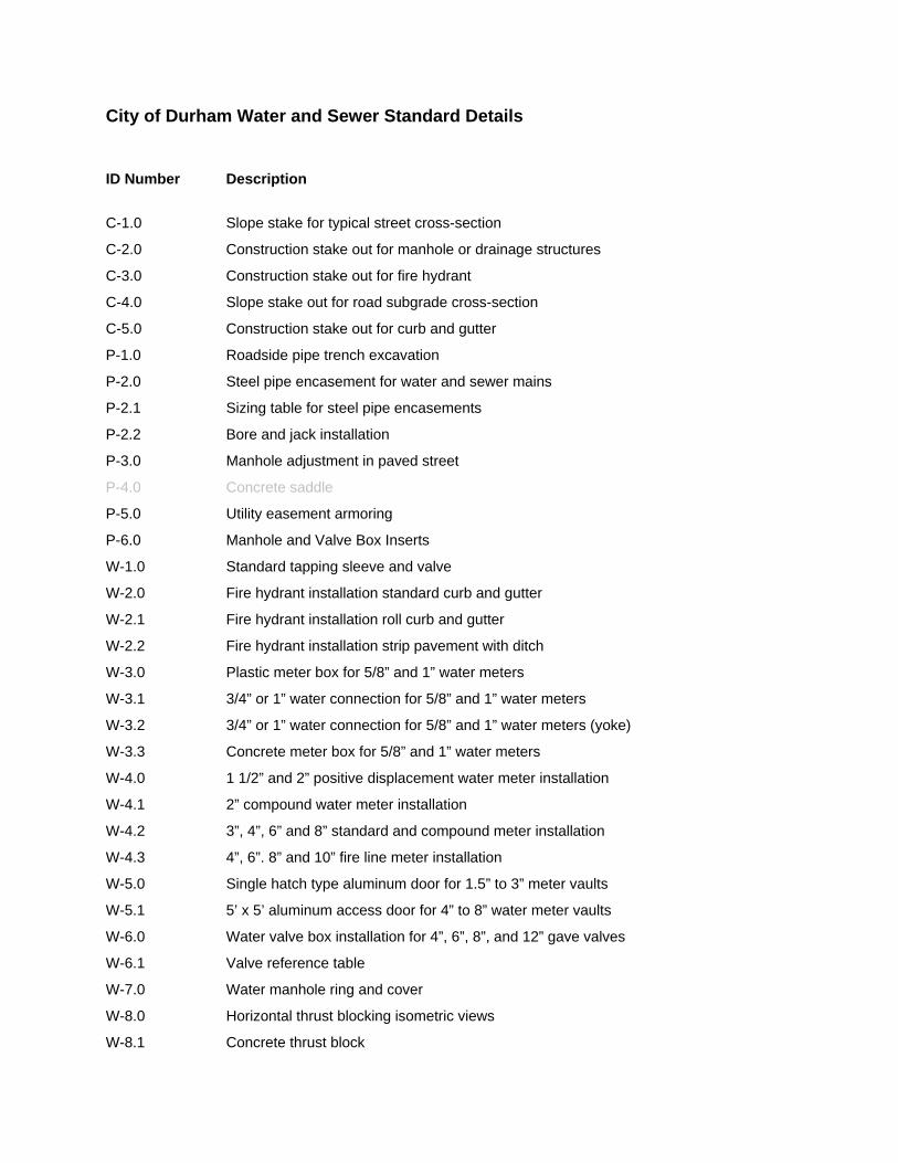
City of Durham Water and Sewer Standard Details
ID Number Description
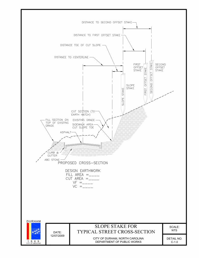
C-1.0 Slope stake for typical street cross-section
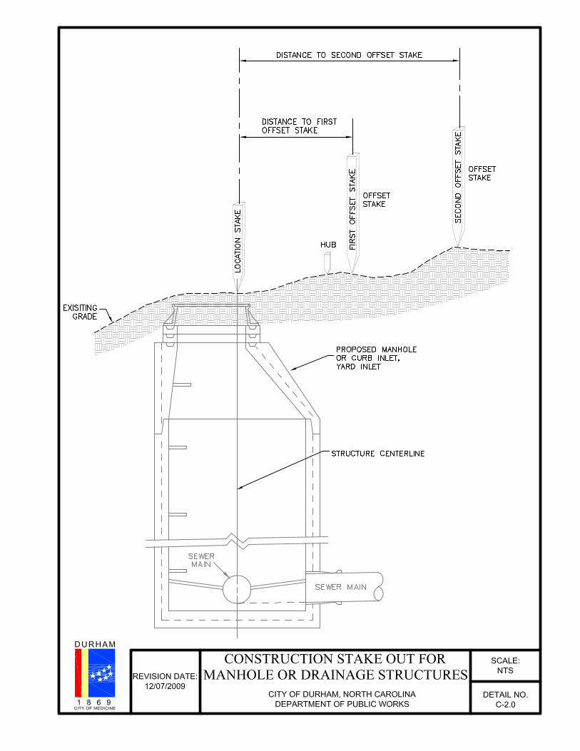
C-2.0 Construction stake out for manhole or drainage structures
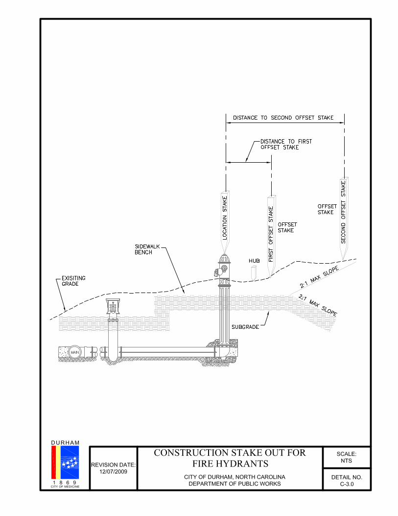
C-3.0 Construction stake out for fire hydrant
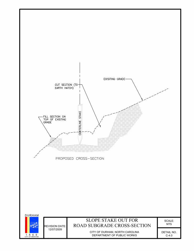
C-4.0 Slope stake out for road subgrade cross-section
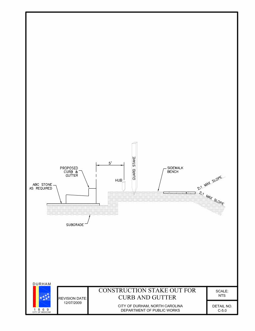
C-5.0 Construction stake out for curb and gutter
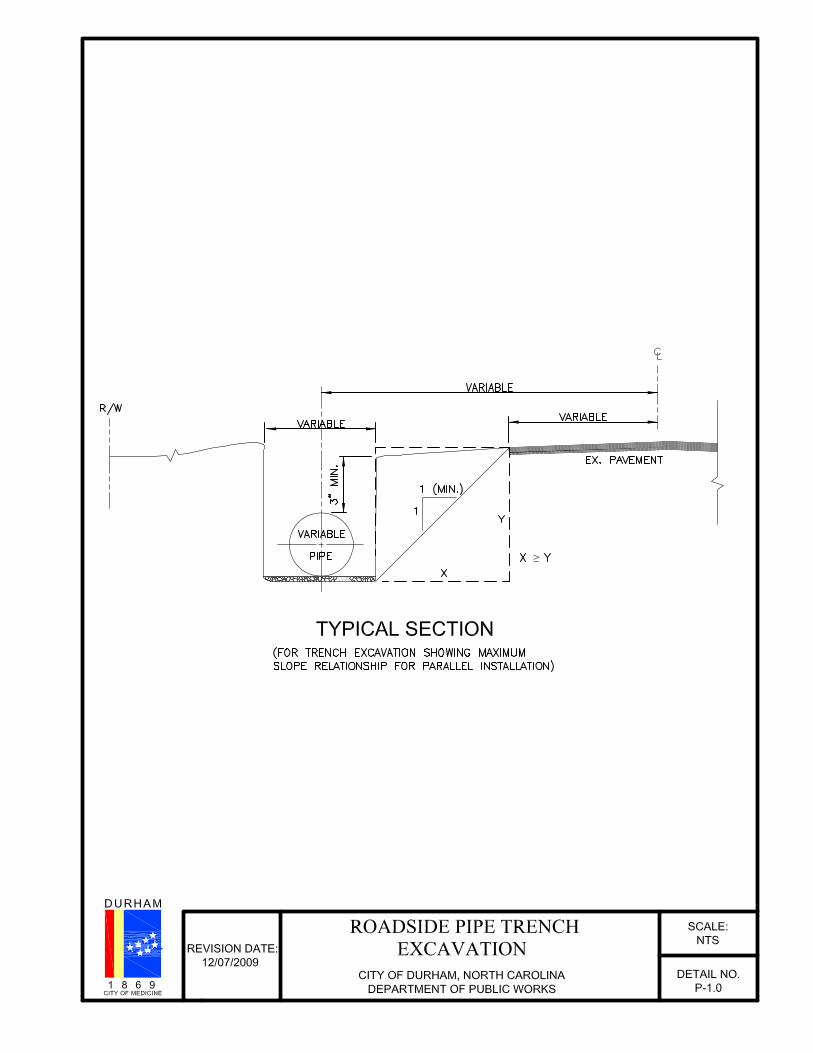
P-1.0 Roadside pipe trench excavation
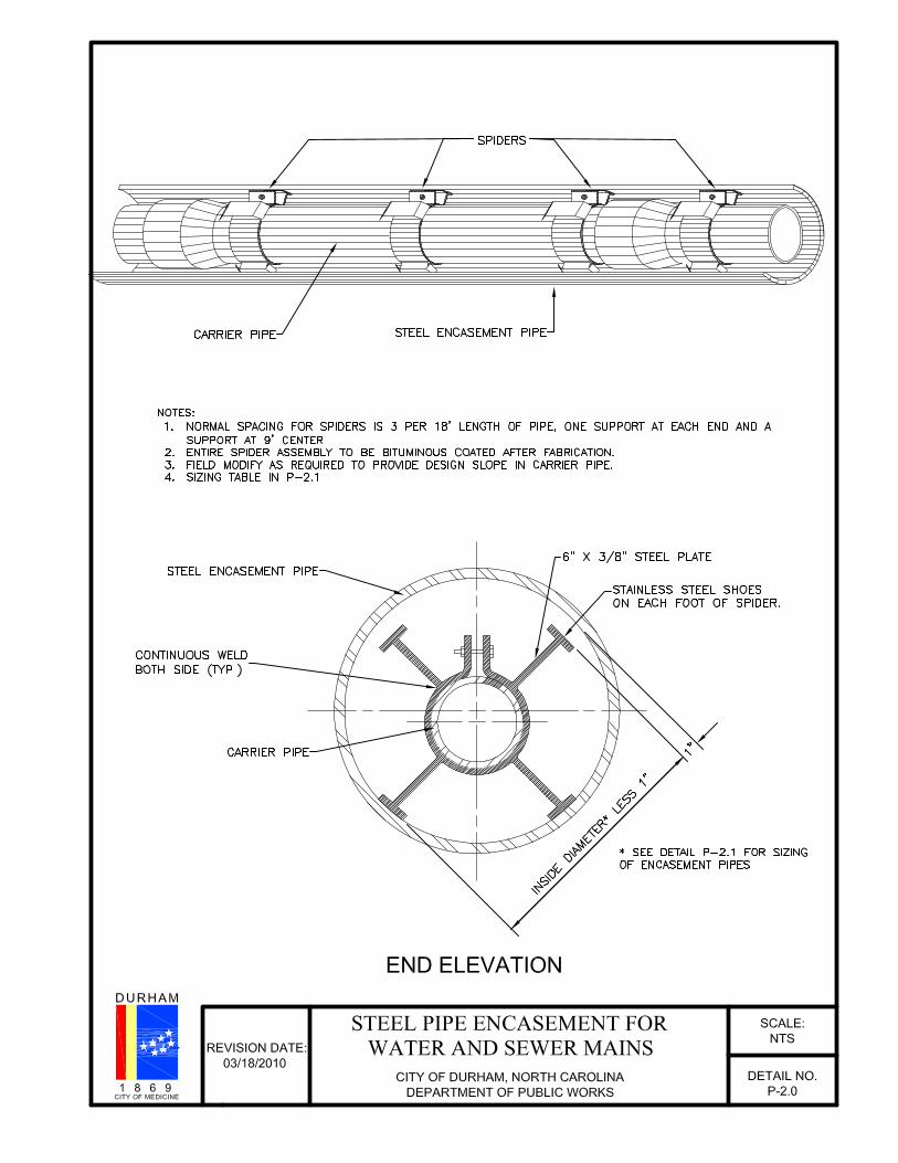
P-2.0 Steel pipe encasement for water and sewer mains
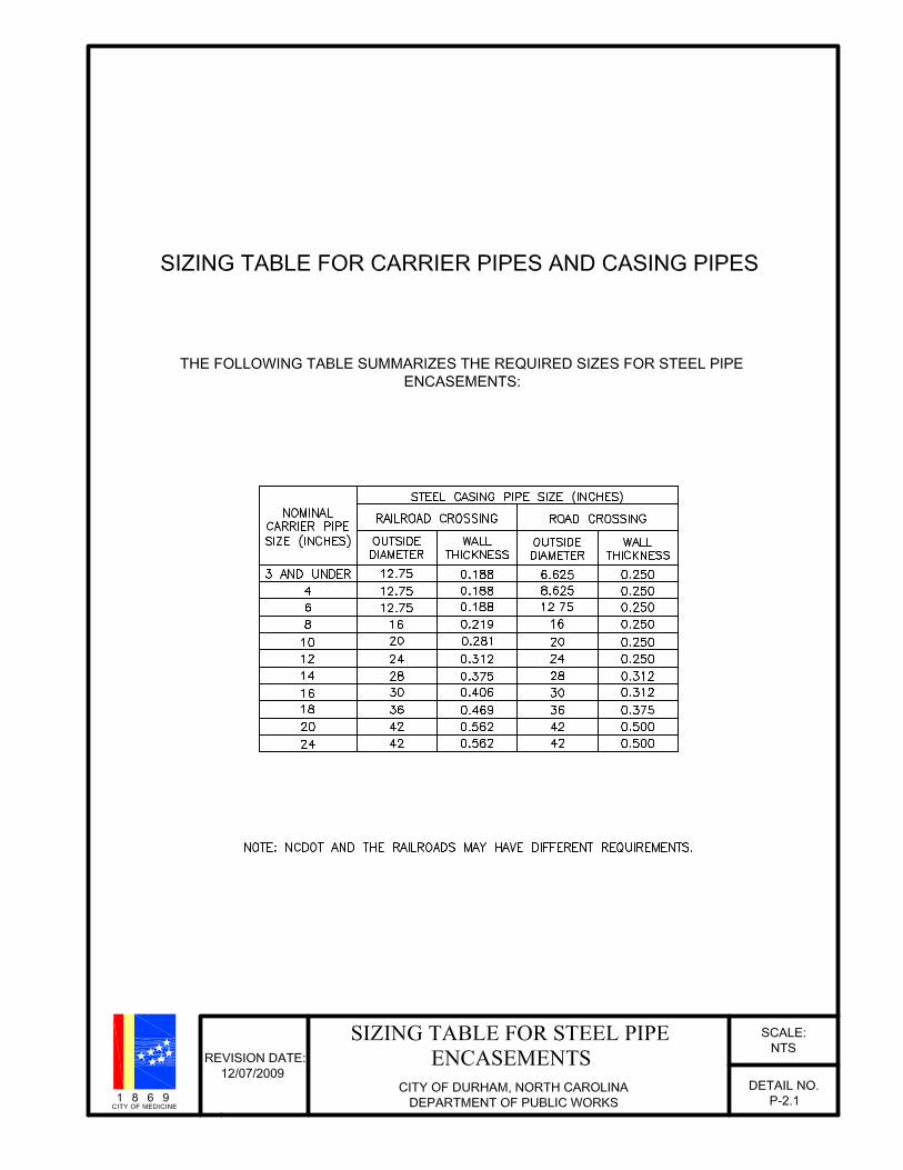
P-2.1 Sizing table for steel pipe encasements
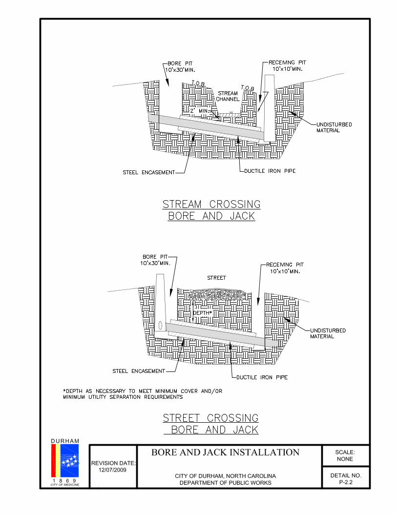
P-2.2 Bore and jack installation
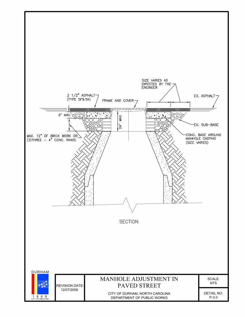
P-3.0 Manhole adjustment in paved street
P-4.0 Concrete saddle
P-5.0 Utility easement armoring
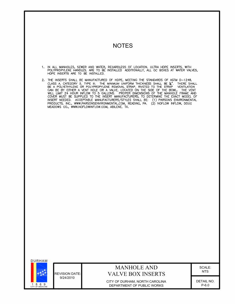
P-6.0 Manhole and Valve Box Inserts
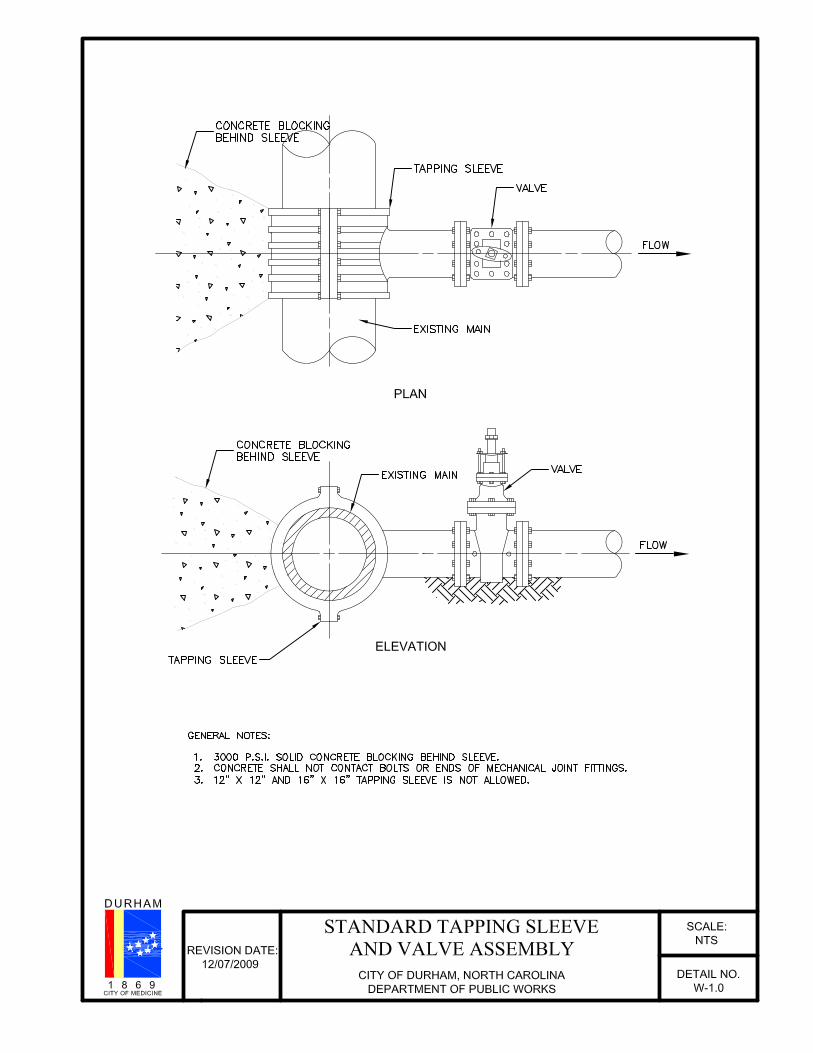
W-1.0 Standard tapping sleeve and valve
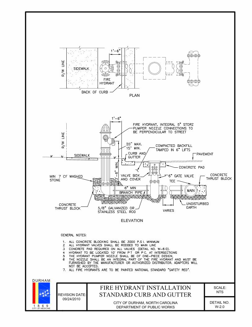
W-2.0 Fire hydrant installation standard curb and gutter
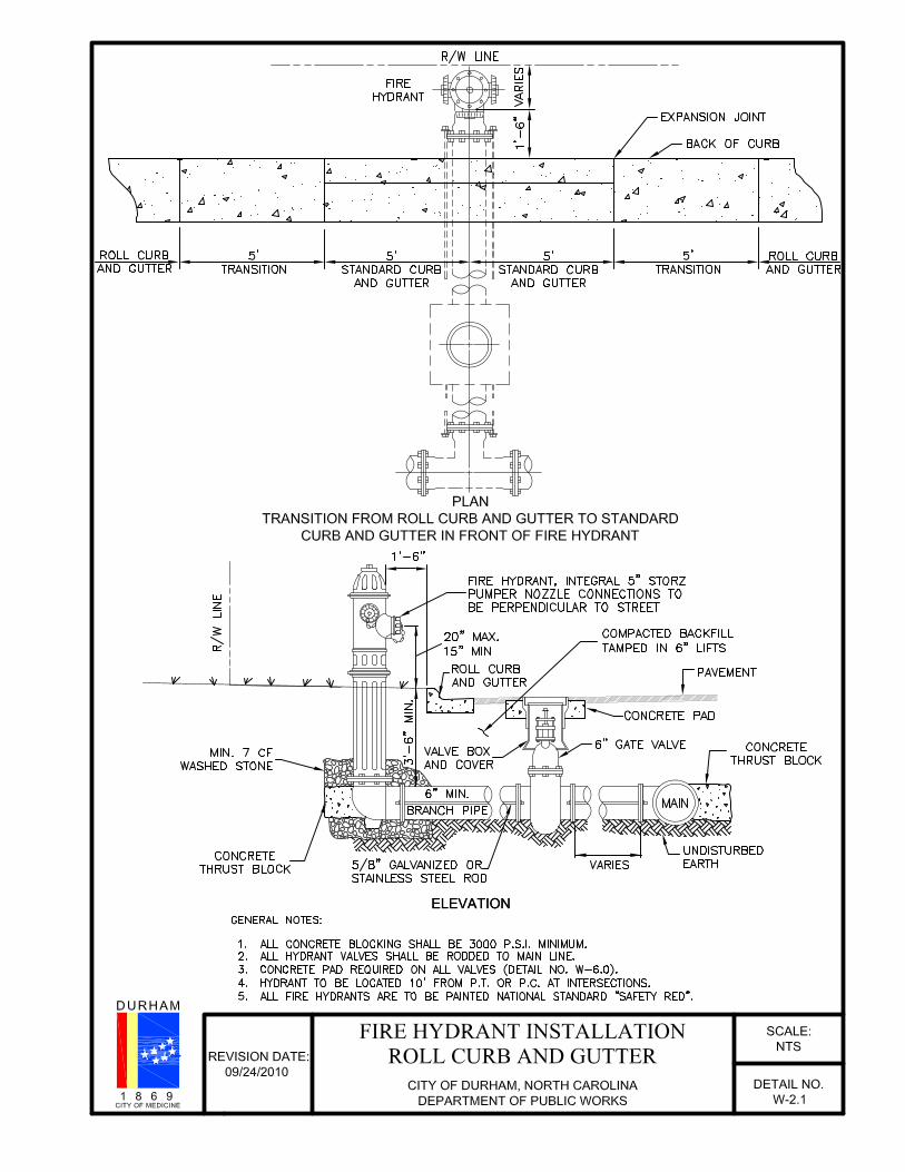
W-2.1 Fire hydrant installation roll curb and gutter
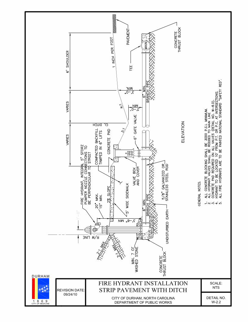
W-2.2 Fire hydrant installation strip pavement with ditch
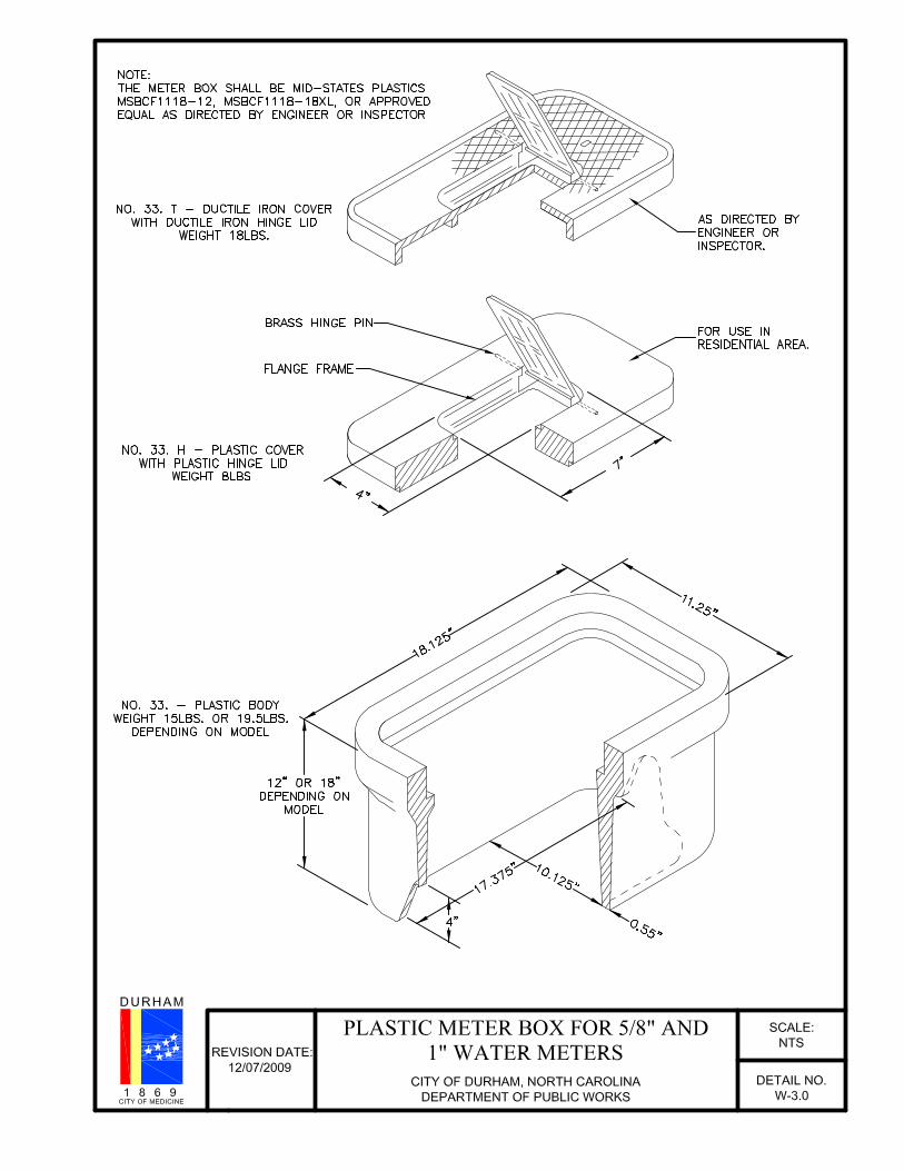
W-3.0 Plastic meter box for 5/8” and 1” water meters
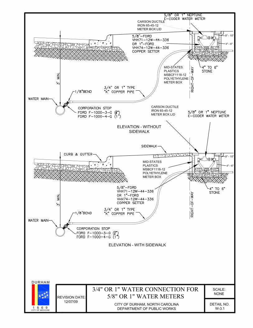
W-3.1 3/4” or 1” water connection for 5/8” and 1” water meters
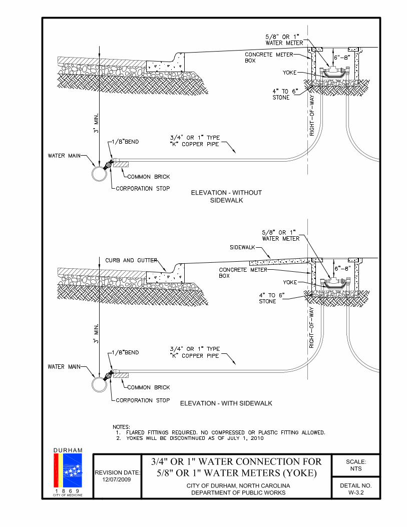
W-3.2 3/4” or 1” water connection for 5/8” and 1” water meters (yoke)
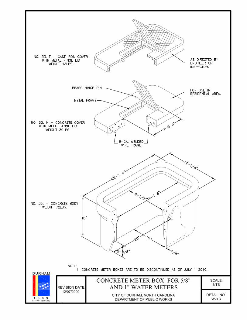
W-3.3 Concrete meter box for 5/8” and 1” water meters
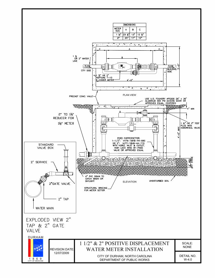
W-4.0 1 1/2” and 2” positive displacement water meter installation
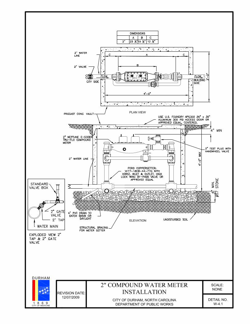
W-4.1 2” compound water meter installation
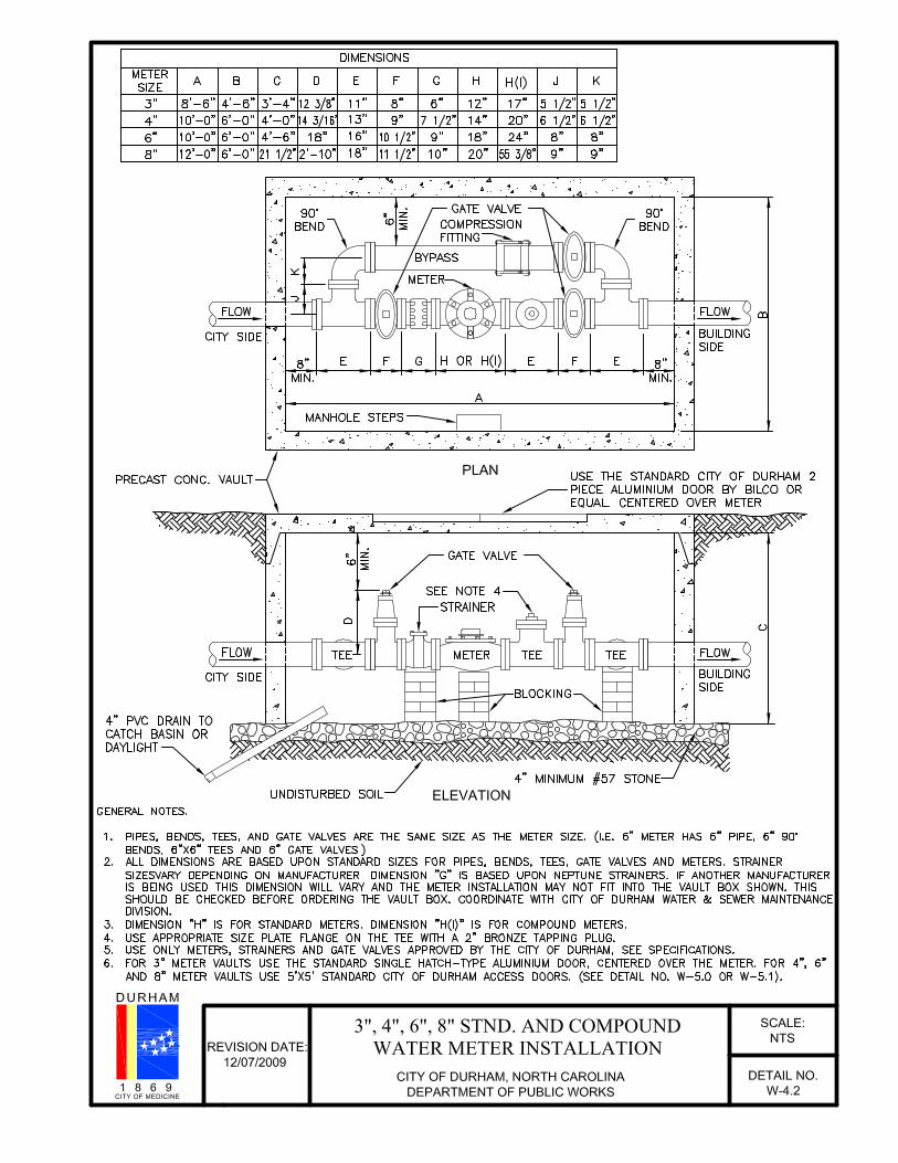
W-4.2 3”, 4”, 6” and 8” standard and compound meter installation
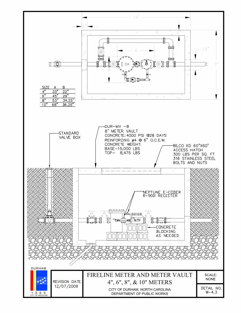
W-4.3 4”, 6”. 8” and 10” fire line meter installation
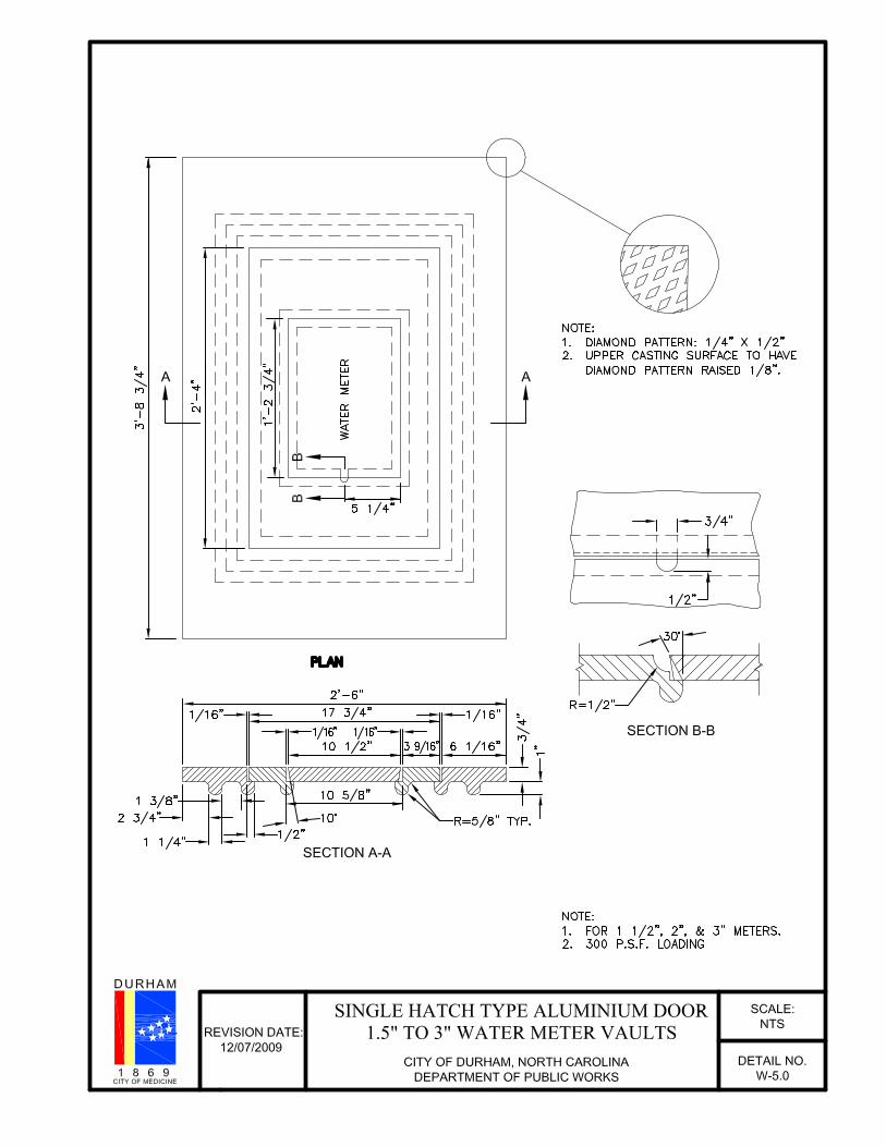
W-5.0 Single hatch type aluminum door for 1.5” to 3” meter vaults
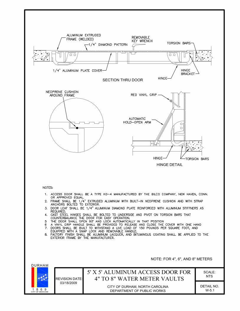
W-5.1 5’ x 5’ aluminum access door for 4” to 8” water meter vaults
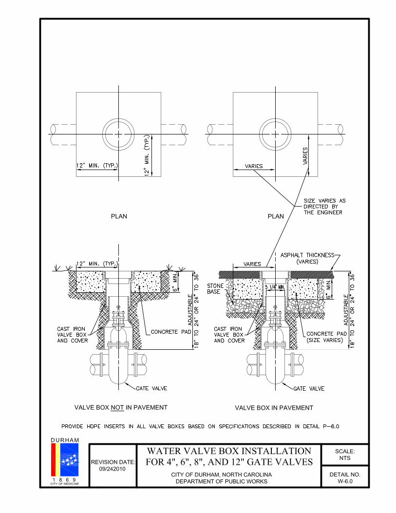
W-6.0 Water valve box installation for 4”, 6”, 8”, and 12” gave valves
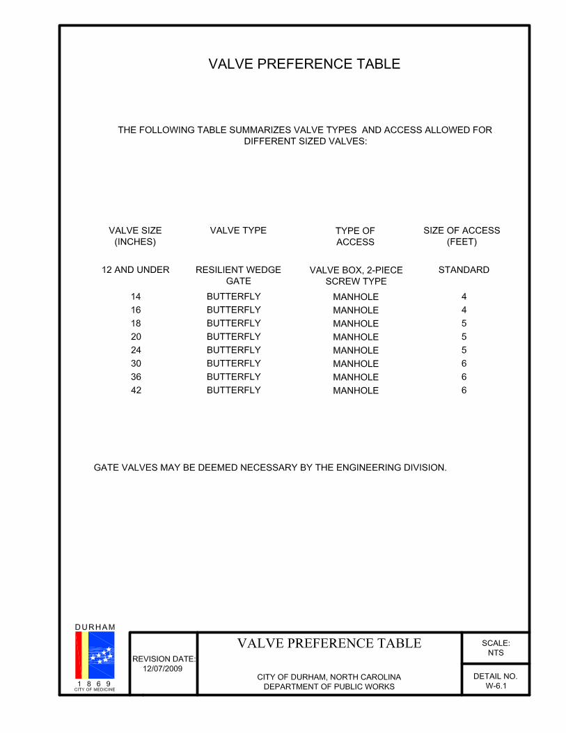
W-6.1 Valve reference table
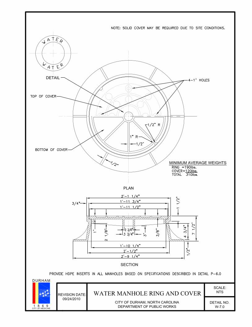
W-7.0 Water manhole ring and cover
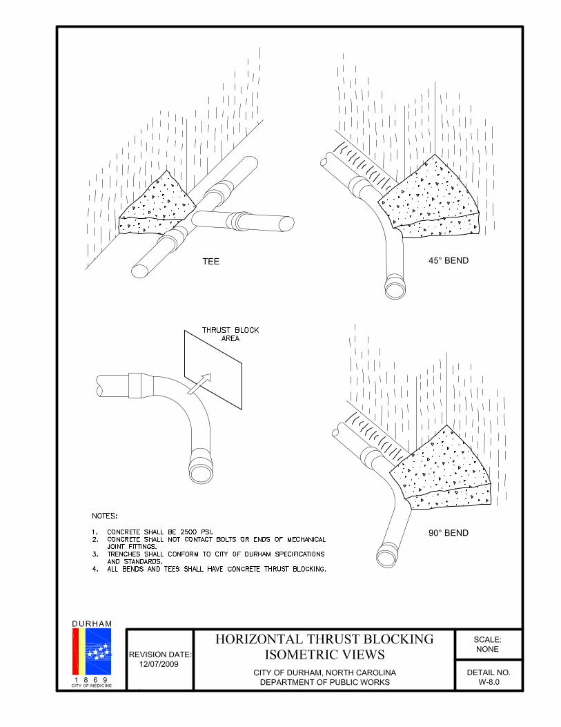
W-8.0 Horizontal thrust blocking isometric views
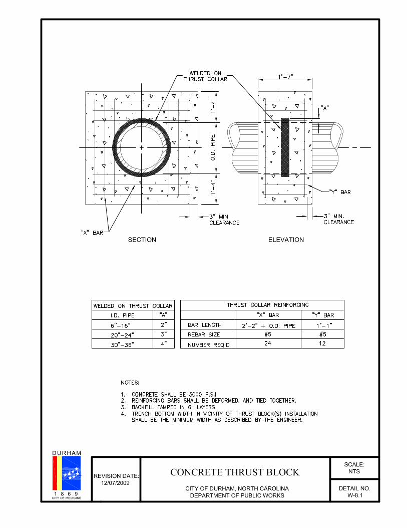
W-8.1 Concrete thrust block
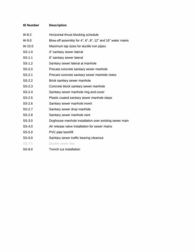
ID Number Description
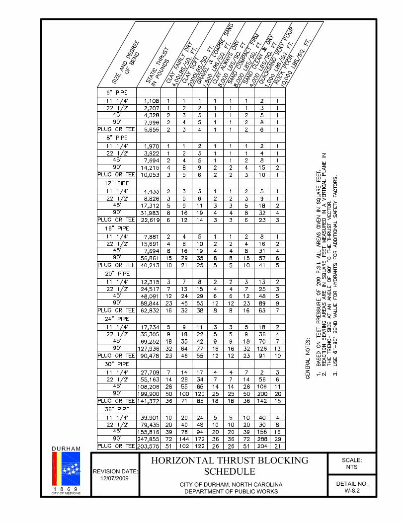
W-8.2 Horizontal thrust blocking schedule
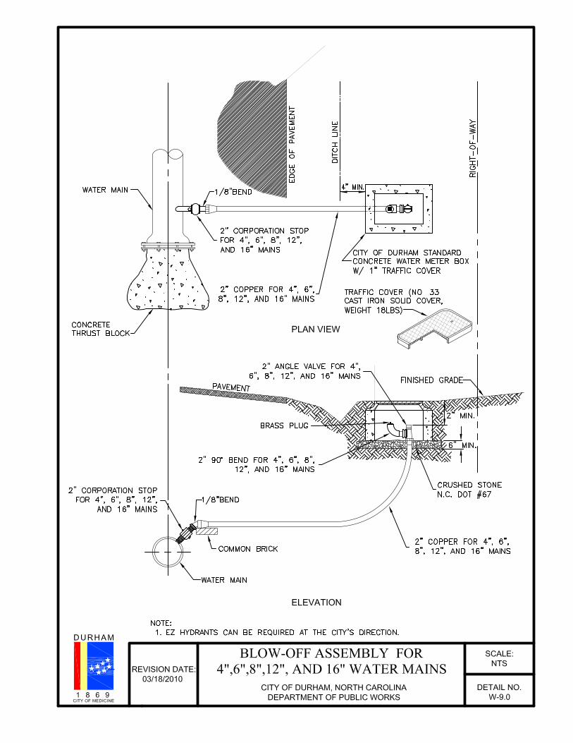
W-9.0 Blow-off assembly for 4”, 6”, 8”, 12” and 16” water mains
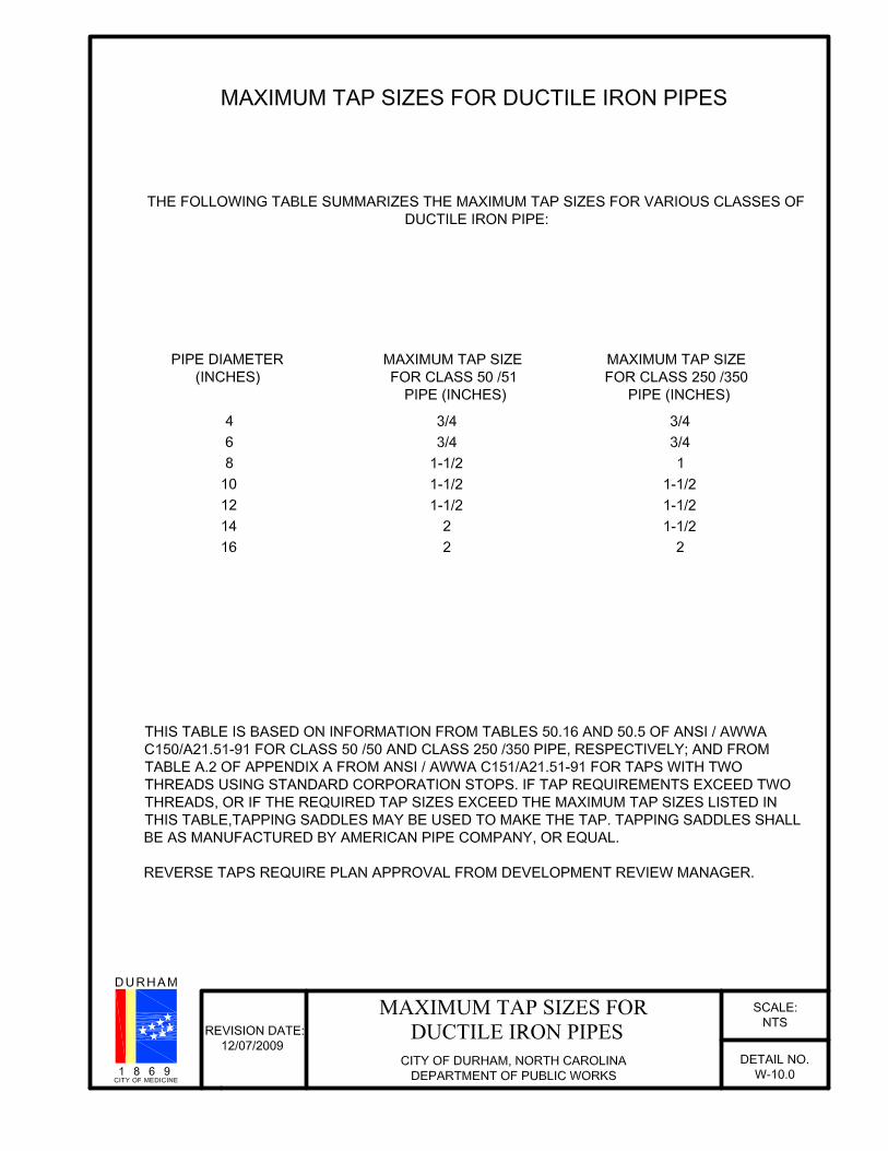
W-10.0 Maximum tap sizes for ductile iron pipes
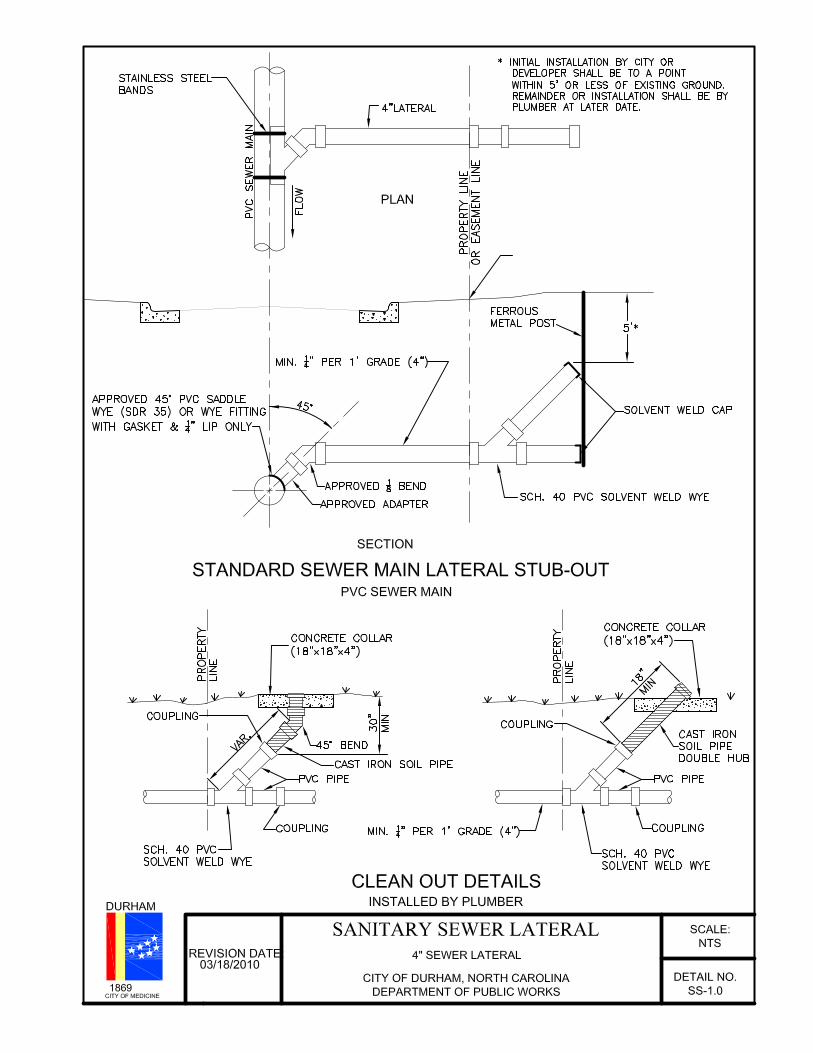
SS-1.0 4” sanitary sewer lateral
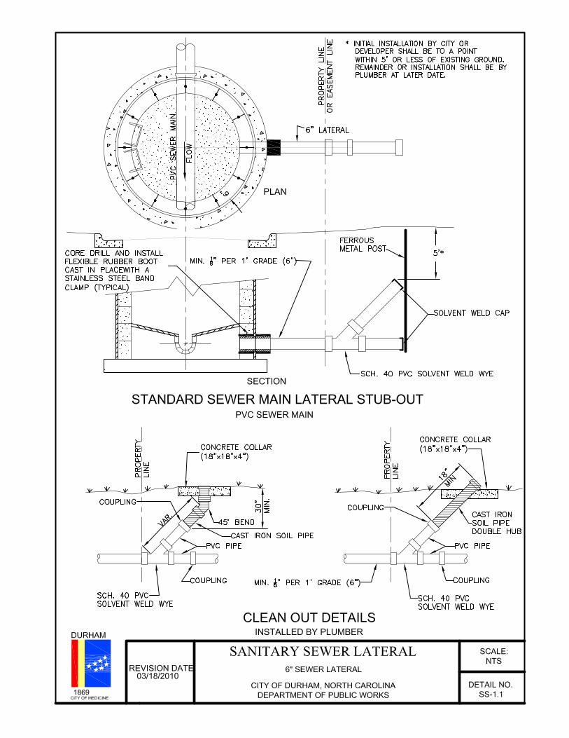
SS-1.1 6” sanitary sewer lateral
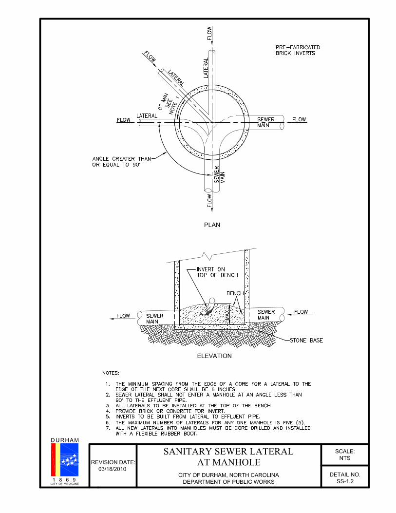
SS-1.2 Sanitary sewer lateral at manhole
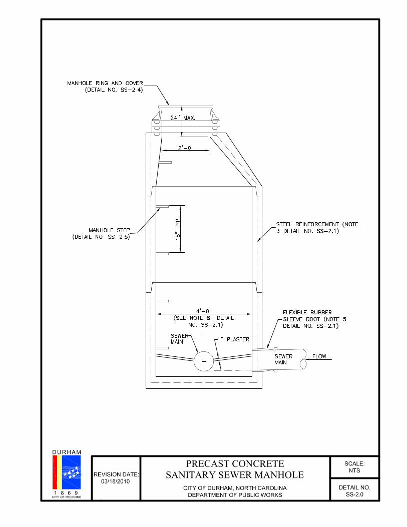
SS-2.0 Precast concrete sanitary sewer manhole
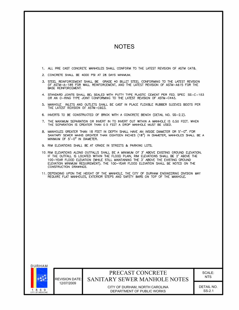
SS-2.1 Precast concrete sanitary sewer manhole notes
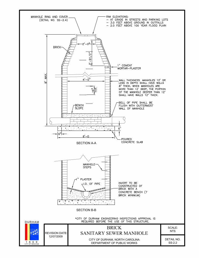
SS-2.2 Brick sanitary sewer manhole
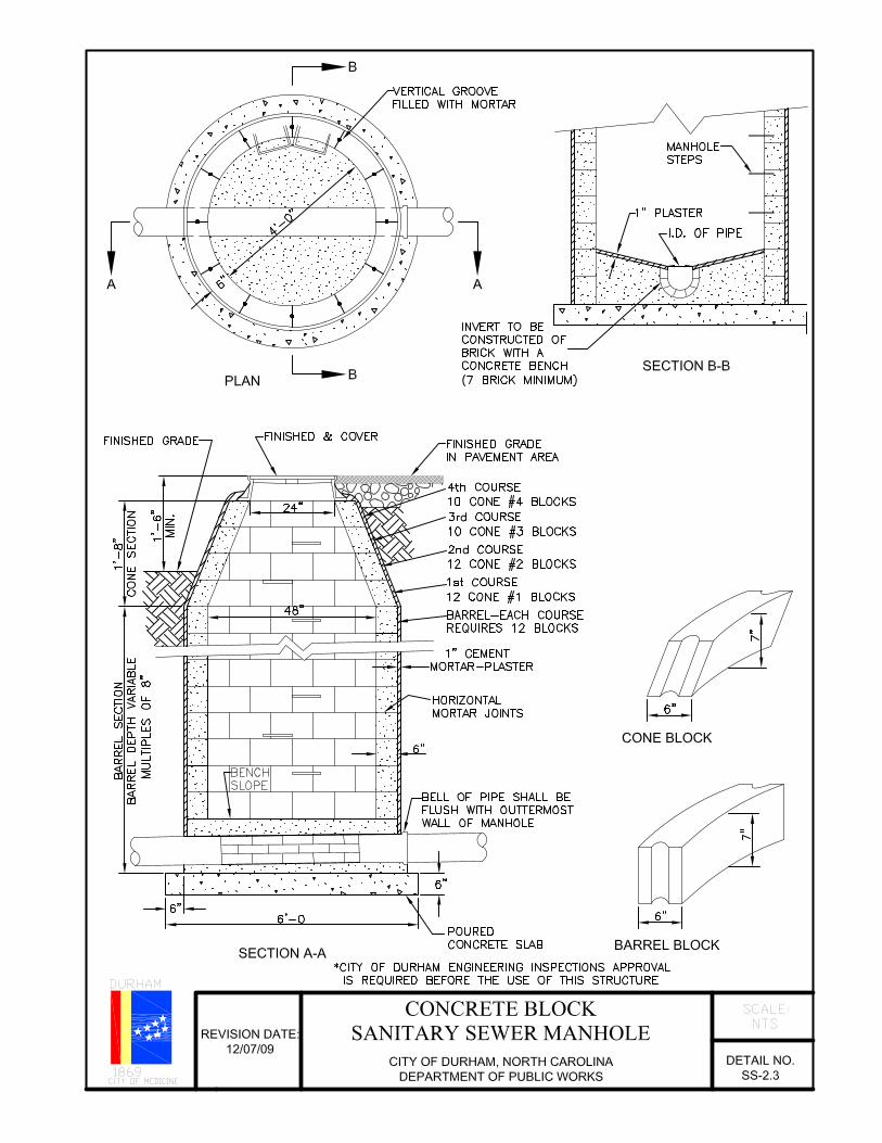
SS-2.3 Concrete block sanitary sewer manhole
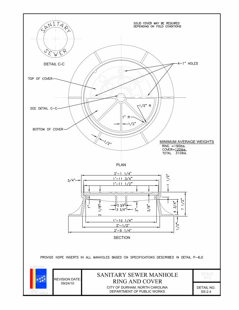
SS-2.4 Sanitary sewer manhole ring and cover
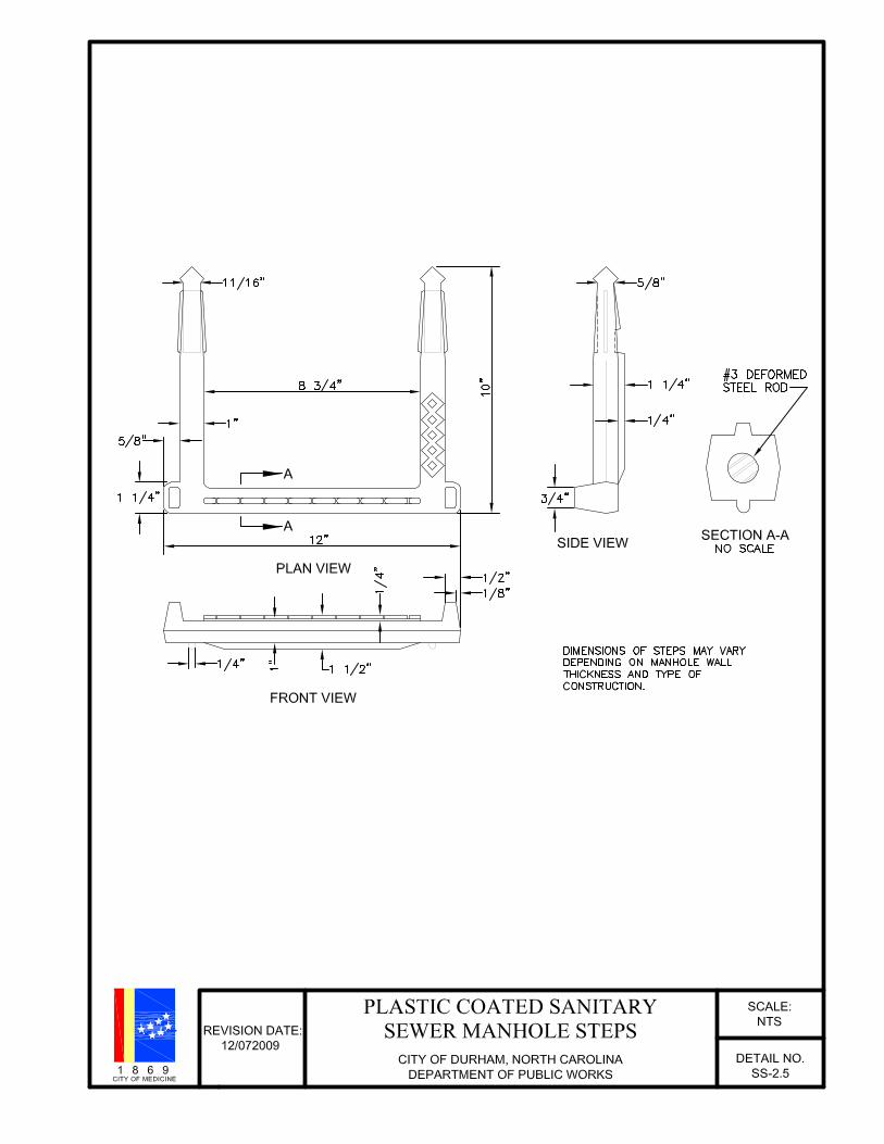
SS-2.5 Plastic coated sanitary sewer manhole steps
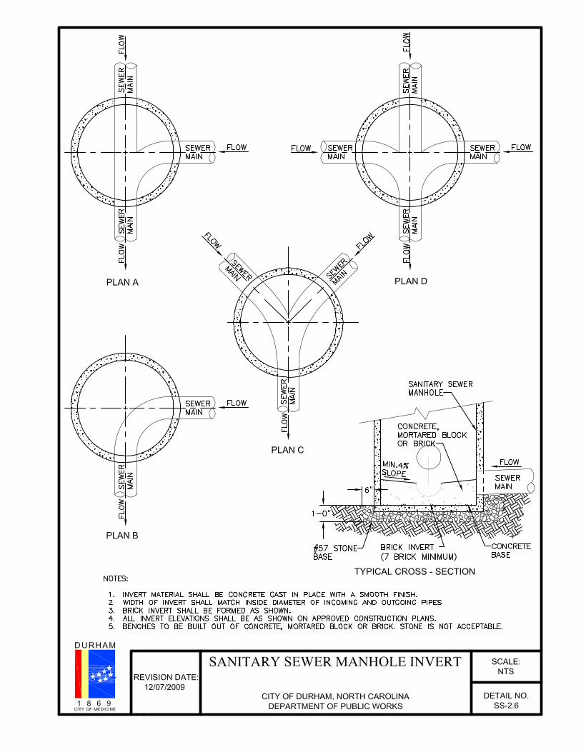
SS-2.6 Sanitary sewer manhole invert
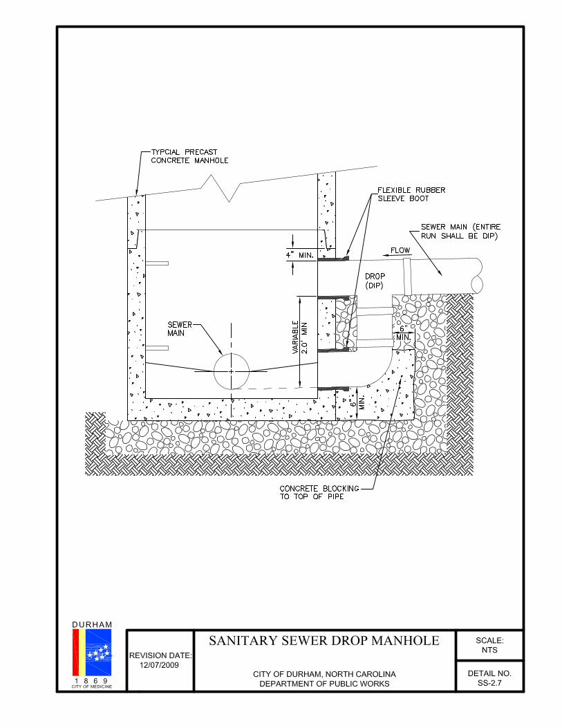
SS-2.7 Sanitary sewer drop manhole
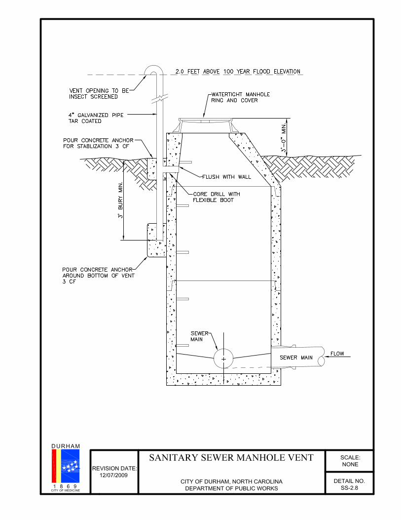
SS-2.8 Sanitary sewer manhole vent
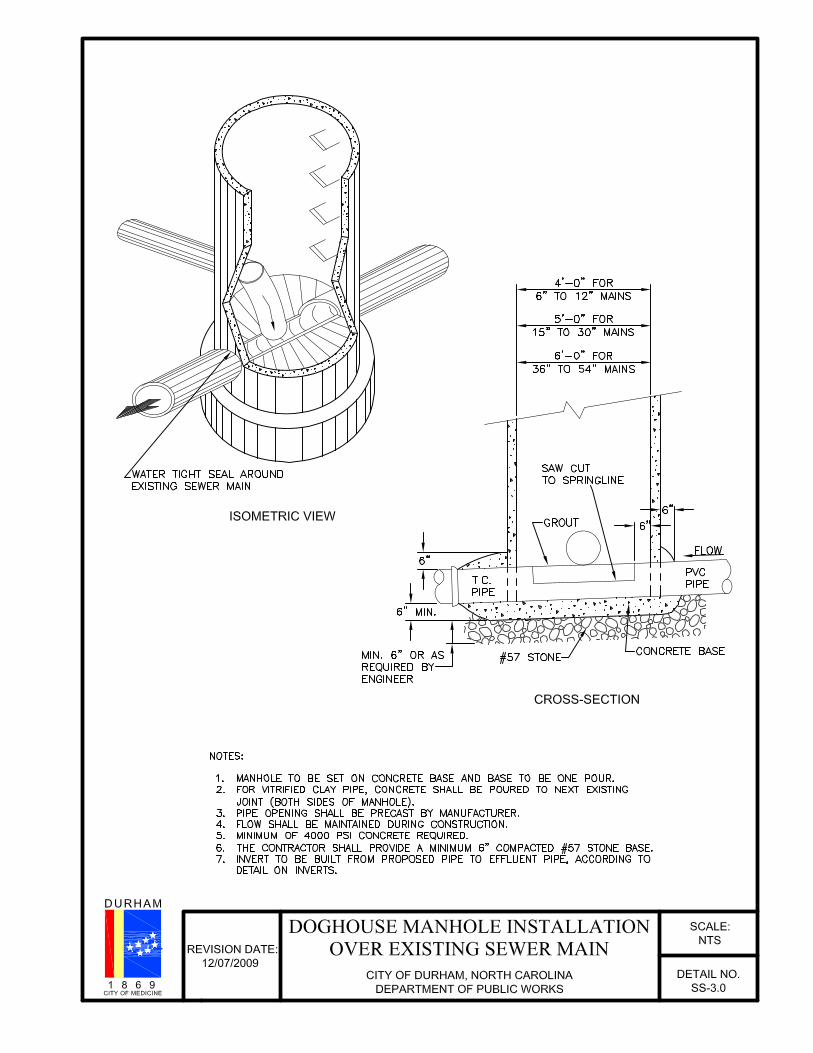
SS-3.0 Doghouse manhole installation over existing sewer main
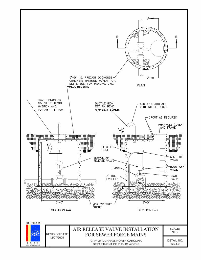
SS-4.0 Air release valve installation for sewer mains
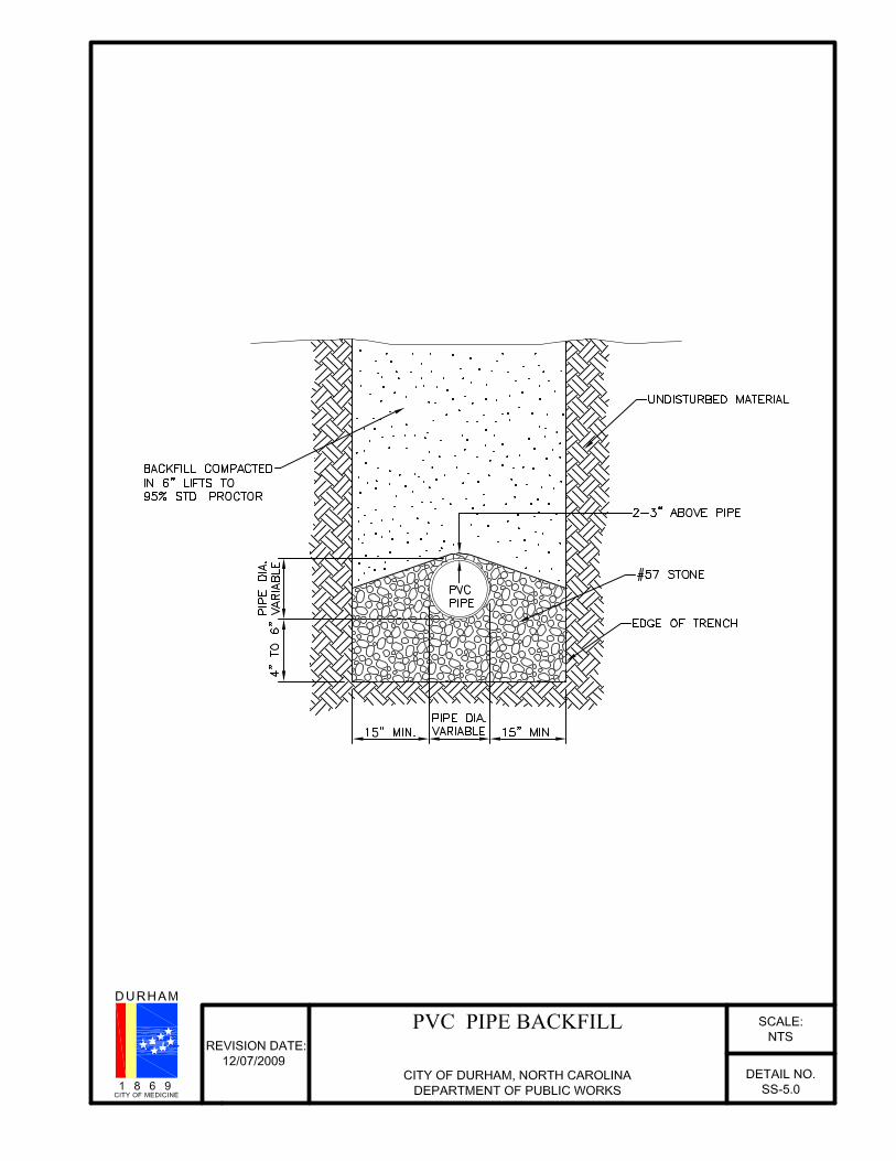
SS-5.0 PVC pipe backfill
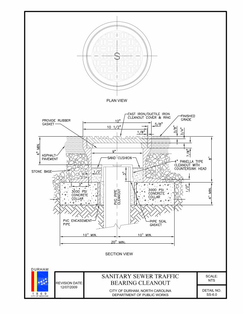
SS-6.0 Sanitary sewer traffic bearing cleanout
SS-7.0 Double sewer line
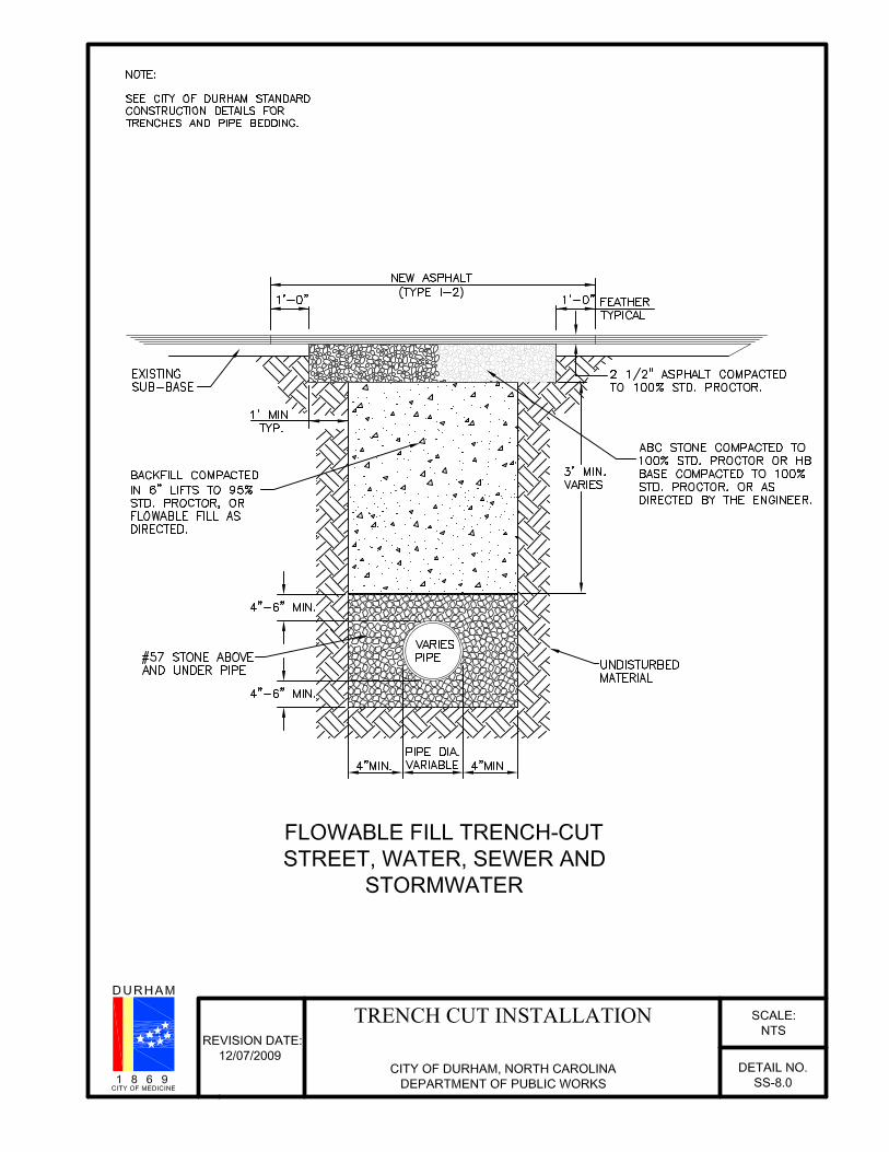
SS-8.0 Trench cut installation