SEWER SYSTEM STANDARD SPECIFICATIONS
29
SEWER SYSTEM STANDARD SPECIFICATIONS Detail Number 1. Parallel lines 2. Standard Manhole 3. Shallow Manhole 4. Typical oil separator 5. Manhole base – branching sewers 6. Manhole base – straight through flow 7. Typical vegetable-animal fat and grease interceptor 8. 9. Hill holder 10. Manhole step detail 11. Side sewer detail 12. Trench cross section for PVC or DI pipe 13. Pipe anchor 14. Low pressure air testing of gravity sewers Part Two – Materials S-1 > S-5 Part Three – Construction S-5 > S-14
Transcript of SEWER SYSTEM STANDARD SPECIFICATIONS

SEWER SYSTEM STANDARD SPECIFICATIONS
Detail Number
1. Parallel lines
2. Standard Manhole
3. Shallow Manhole
4. Typical oil separator
5. Manhole base – branching sewers
6. Manhole base – straight through flow
7. Typical vegetable-animal fat and grease interceptor
8.
9. Hill holder
10. Manhole step detail
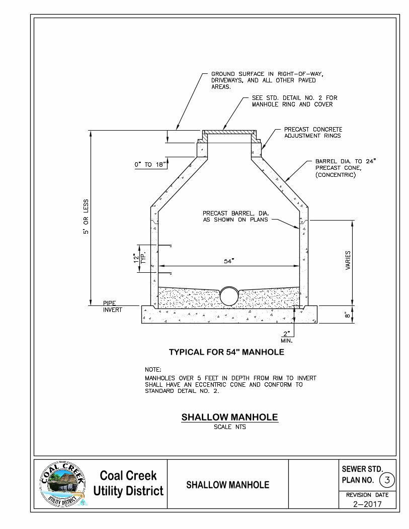
11. Side sewer detail
12. Trench cross section for PVC or DI pipe
13. Pipe anchor
14. Low pressure air testing of gravity sewers
Part Two – Materials
S-1 > S-5
Part Three – Construction
S-5 > S-14

DETAIL NO.1PARALLEL CONSTRUCTION

TYPICAL FOR 54" MANHOLE
STANDARD MANHOLE
TYPICAL FOR 54" MANHOLE
SHALLOW MANHOLE

TYPICAL OIL SEPARATOR (450 GAL. MIN.)

PLAN
MANHOLE BASE - BRANCHING SEWERS

PLAN
ELEVATION
MANHOLE BASESTRAIGHT THROUGH FLOW

TYPICAL VEGETABLE-ANIMALFAT & GREASE INTERCEPTOR

PLAN
ELEVATION
HILL HOLDER

MANHOLE STEP DETAILS
MANHOLE STEPS
STD. BASE SECTION LADDER
SINGLE SERVICE
STANDING SERVICE
CAST IRON RINGAND COVER
CLEAN OUT COVER
GASKET XMALE ADAPTOR

TRENCH CROSS SECTIONFOR P.V.C. OF D.I. PIPE

SECTION A-A
PIPE ANCHOR

LOW PRESSUREAIR TESTING OF
GRAVITY SEWERS
LOW PRESSURE AIR TESTINGOF GRAVITY SEWERS
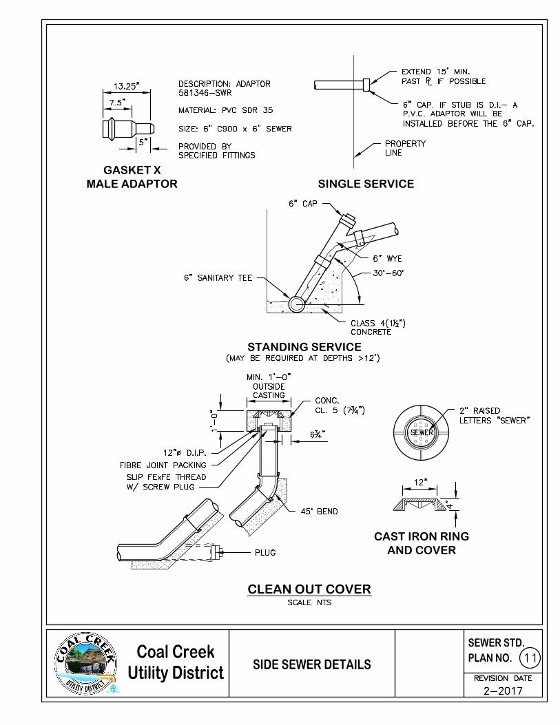
ACCESS ROADS

S-1
PART TWO – MATERIALS
NOTE:
"Developer" in these specifications shall also signify "Contractor" for the purpose of
District financed projects.
2-1 GENERAL
All materials and equipment shall be new and workmanship and materials shall be good quality. All material incorporated into the work shall conform to the provisions of this part. All references to Specifications shall be of the latest edition.
2-2 MATERIAL LISTS AND SPECIFICATIONS
The Developer or his Contractor shall deliver to the Engineer a material list not less than ten (10) days before commencement of construction. The list shall contain the manufacturer and model number, if applicable, of the material and equipment to be installed as a part of the work so that the Engineer may determine whether such materials conform to the Plans and Specifications. No materials that are not included in the material list shall be installed as a part of the work. The manufacturer's technical specifications for pipe, appurtenances and equipment to be incorporated into the work shall be submitted to the Engineer at least ten (10) days prior to commencement of construction with the materials listed.
2-3 GUARANTEE BY MANUFACTURER
If requested by the District or the Engineer, a written guarantee made by the manufacturer of any materials to be incorporated into the work shall be furnished, guaranteeing to the District that such materials shall conform to these Specifications and any specifications otherwise applying to the work.
2-4 SEWER PIPE AND APPURTENANCES, NON-PRESSURE
Non-pressure sewer pipe shall be PVC pipe conforming to ASTM D-3034 for depths of cover between 5 feet to 12 feet; and Ductile Iron pipe, class 50, conforming to AWWA Standard C-151 for depths of cover less than 5 feet or exceeding 12 feet and for slopes less than 1% and over 15%. Pipes installed at slopes 15% or greater shall incorporate "Field Lok" gaskets for the entire run. Ductile iron pipe and fittings shall be epoxy lined with Induron Protecto 401TM Ceramic Epoxy, or approved equal. Cement mortar lining is not allowed. Cut ends shall be sealed and damaged areas repaired in accordance with the manufacturer’s recommendations.
PVC sewer pipe is defined as flexible conduit. Joints shall conform to ASTM D-3212 using a restrained rubber gasket conforming to ASTM F-477. Fittings shall be injection molded tees or factory solvent welded saddle tees. Saddles fastened to pipe with external bands are not acceptable on any new system.

S-2
Ductile Iron pipe is defined as rigid conduit. Mechanical or push-on joints shall conform to AWWA Standard C-110.
2-5 SEWER PIPE AND APPURTENANCES – PRESSURE
Unless otherwise specified, pressure pipe shall be constructed of:
(a) High Density Polyethylene (HDPE) pipe conforming to ASTM 3035 with the type of joint, class, thickness, designation and markings as specified.
(b) Cast Iron fittings shall be rubber-gasket and shall conform to AWWA C-110 and C-111. HDPE fittings shall be as called out on the plans. Valves shall conform to AWWA Specifications C-500.
2-6 MANHOLES – 54” STANDARD
(a) Manhole Frames and Covers
Cast Iron frames and covers shall conform to the Olympic Foundry Company No. MH30A, or equivalent. Castings shall conform to the requirements of ASTM A48, class 30 and shall be free of porosity, shrink cavities, cold shuts, or cracks or any surface defects which would impair serviceability. Repair of defects by welding or by the use of "smooth-on" or similar material will not be permitted. Cover to be non-skid type surface and shall have the word "SEWER" in large raised letters.
A bituminous coating shall be applied to all surfaces. The finished coating shall be continuous, smooth, neither brittle when cold nor sticky when exposed to the sun, and shall be strongly adherent to the casting. The District shall have the right to require inspection and approval of all castings prior to painting. Manhole rings and covers shall be machine finished or ground on seating surfaces to assure non-rocking fit in any position. At the request of the District, there shall be made available at the foundry standard rings and standard covers for use by inspectors in testing fit and seating.
Manholes located outside public rights-of-way shall be equipped with a locking device of such design that the cover may be readily released from the ring. All movable parts shall be made of non-corrosive metals otherwise arranged to avoid possible binding. At the request of the District, there shall be made available at the foundry a testing device suitable for proving the capacity of the assembly to resist an uplift pressure on the lid equal to a 20-foot head. The locking frame and cover shall be Metro standard frame and cover with 3-screw-type locking lids.
All manhole frames and covers shall be identified by the name or symbol of the manufacturer. This identification shall be in a plainly visible location when the frames and covers are installed. In addition to the manufacturer's identification, the material shall be identified by the following "NOD" or "DUC" for nodular or ductile iron respectively. The manufacturer's identification and the material
S-3
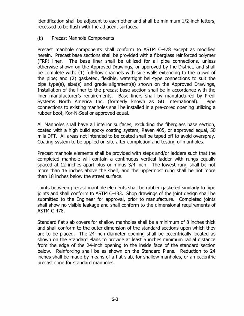
identification shall be adjacent to each other and shall be minimum 1/2-inch letters, recessed to be flush with the adjacent surfaces.
(b) Precast Manhole Components
Precast manhole components shall conform to ASTM C-478 except as modified herein. Precast base sections shall be provided with a fiberglass reinforced polymer (FRP) liner. The base liner shall be utilized for all pipe connections, unless otherwise shown on the Approved Drawings, or approved by the District, and shall be complete with: (1) full-flow channels with side walls extending to the crown of the pipe; and (2) gasketed, flexible, watertight bell-type connections to suit the pipe type(s), size(s) and grade alignment(s) shown on the Approved Drawings, Installation of the liner to the precast base section shall be in accordance with the liner manufacturer’s requirements. Base liners shall by manufactured by Predl Systems North America Inc. (formerly known as GU International). Pipe connections to existing manholes shall be installed in a pre-cored opening utilizing a rubber boot, Kor-N-Seal or approved equal.
All Manholes shall have all interior surfaces, excluding the fiberglass base section, coated with a high build epoxy coating system, Raven 405, or approved equal, 50 mils DFT. All areas not intended to be coated shall be taped off to avoid overspray. Coating system to be applied on site after completion and testing of manholes.
Precast manhole elements shall be provided with steps and/or ladders such that the completed manhole will contain a continuous vertical ladder with rungs equally spaced at 12 inches apart plus or minus 3/4 inch. The lowest rung shall be not more than 16 inches above the shelf, and the uppermost rung shall be not more than 18 inches below the street surface.
Joints between precast manhole elements shall be rubber gasketed similarly to pipe joints and shall conform to ASTM C-433. Shop drawings of the joint design shall be submitted to the Engineer for approval, prior to manufacture. Completed joints shall show no visible leakage and shall conform to the dimensional requirements of ASTM C-478.
Standard flat slab covers for shallow manholes shall be a minimum of 8 inches thick and shall conform to the outer dimension of the standard sections upon which they are to be placed. The 24-inch diameter opening shall be eccentrically located as shown on the Standard Plans to provide at least 6 inches minimum radial distance from the edge of the 24-inch opening to the inside face of the standard section below. Reinforcing shall be as shown on the Standard Plans. Reduction to 24 inches shall be made by means of a flat slab, for shallow manholes, or an eccentric precast cone for standard manholes.

S-4
(c) Deformed Bar Steps
Polypropylene coated steps shall conform to ASTM C-478 with deformed bar
conforming to ASTM A-615. Steps shall be Lane model P-14938 or approved equal.
Step dimensions and pattern shall conform to the Standard Plans.
(d) Ladders
Precast manhole base sections more than three feet in height shall be provided
with a ladder as detailed on the Standard Plans. Ladders shall be polypropylene
coated.
2-7 IMPORTED BACKFILL
Imported backfill material shall be free from wood, bark, roots or other extraneous
material and shall meet the requirements of WSDOT Section 9-03.19 for Bank Run
Gravel for Trench Backfill.
PEA GRAVEL WILL NOT BE ALLOWED AS BACKFILL MATERIAL.
2-8 TRENCH FOUNDATION MATERIAL
Over-excavated material shall be replaced with trench foundation material conforming
with the requirements of WSDOT Section 9-03.17 for Foundation Material Class A and
Class B.
2-9 BEDDING MATERIAL
Bedding material shall be well-graded, clean, granular material, commonly known as
pea gravel and shall meet the following requirements:
U.S. Standard % Passing Sieve Size By Weight
3/8" square opening 100 #8 sieve 0-5
2-10 ASPHALTIC CONCRETE
Asphalt concrete pavement shall conform to the technical requirements of the current edition of the Standard Specifications for Road, Bridge and Municipal Construction as published by the Washington State Department of Transportation.
2-11 TOP COURSE AND KEYSTONE MATERIAL

S-5
For use in the restoration of excavated areas, Top Course and Keystone material shall be manufactured from ledge or talus rock, be free from wood, roots, bark and other extraneous material and shall conform to the requirements of WSDOT Section 9-03.9(3) for Crushed Surfacing Top Course.
2-12 BASE COURSE MATERIAL
Base course material shall conform to the requirements of WSDOT Section 9-03.9(3) for Crushed Surfacing Base Course.
2-13 CONCRETE BEDDING AND BLOCKING
Bedding and blocking concrete shall be Portland cement concrete containing four sacks of cement per cubic yard and maximum aggregate size of 1-1/2 inches. Maximum slump shall be 3-1/2 inches.
PART THREE - CONSTRUCTION
3-1 GENERAL
Except as otherwise noted herein, all work shall be accomplished as recommended in the latest revision of the AWWA and APWA Specifications and according to the recommendations of the manufacturer of the material and equipment concerned. All specified depths shall be compacted depths.
In roadway areas, all asphalt and concrete pavement shall be saw cut. When trenching operations cut through concrete pavement, the pavement shall be removed to a width of 18 inches greater than the top width of the trench. The concrete shall be saw cut on a straight line and shall be beveled so that the cut will be approximately 1 inch wider at the top than at the bottom. Asphalt paving shall be saw cut ahead of the backhoe to prevent excessive tearing up of the surfacing and to eliminate ragged edges.
3-2 TRENCH EXCAVATION
Trenches shall be excavated to the line and grade designated by the District. Unless otherwise specified, trench sides shall be excavated vertically. Trench widths shall be adequate for proper working space and placement of bedding material under and around the pipe. The trench width, from the bottom of the trench to 4" above the crown of the pipe, shall not exceed 40 inches for 15-inch diameter and smaller pipe, or 1.5 times the inside diameter of 18-inch or larger pipe, plus 18 inches. If these widths are exceeded, a stronger grade of pipe and/or a higher classification and amount of bedding material shall be furnished, as directed by the District.

S-6
Excavation for manholes or other structures shall be sufficient to provide a minimum of 18 inches between the structure and the sides of the excavation, enough to allow for proper compaction of the surrounding backfill.
All material excavated from trenches and piled next to the trench, shall be placed and maintained so that the top of the material is at least 2 feet from the edge of the trench. Excavated material shall be located so that free access is provided to all fire hydrants, water valves, meters and other utilities, and clearance shall be left to enable free flow of storm water in all gutters, conduits and natural water courses.
3-3 TIMBERING AND SHEETING
The developer shall provide and install timbering and sheeting as necessary to protect workers, the work, existing buildings, utilities and other properties, and shall meet all OSHA and WISHA requirements.
3-4 JACKED OR BORED CROSSING
All work shall be done in conformance with the requirements of the agency in control of the facility being bored or jacked. See Roadway and Railway Crossings for further details.
3-5 ROADWAY AND RAILWAY CROSSINGS
Any method may be used for roadway or railway crossings that provides for satisfactory results and is acceptable to both the District and the governmental or private agency having control of the road or track, provided that the road or track shall be restored to its original condition after the crossing is completed. If tunneling or jacking is elected or required for crossings, steel, cast iron or concrete pipe casing shall be placed and the sewer pipe laid within the casing. For District Standards for boring or tunneling see "Water or Sewer Casing Detail" on separate sheet.
3-6 TRENCH FOUNDATION
If, in the judgment of the District, the native trench bottoms will provide a firm base for the subsequent placement of bedding, pipe and backfill, such native trench bottom may be used if the bottom is leveled and smoothed so that the entire length of pipe will rest on a well-compacted base. Trench bottoms shall be over-excavated as necessary to remove all unstable soil and eliminate "boiling" or "quick" conditions to such a depth as to provide a firm base. Over-excavated materials shall be replaced with trench foundation material as specified in Section 2-8. Foundation material shall be placed when ordered by the District.

S-7
3-7 BEDDING MATERIAL PLACEMENT
All pipe shall be placed in bedding material of the type specified in Section 2-9. The bedding shall be placed from a minimum of 4 inches below the pipe barrel to 4 inches above the pipe as shown on the Standard Detail. Bedding material shall be worked by hand under, around and over the pipe to the depths required for the full width of the trench.
Bedding shall be placed in more than one lift. The first lift, to provide at least 4-inch thickness under any portion of the pipe, shall be placed before the pipe is installed and shall be spread smoothly so that the pipe is uniformly supported along the barrel. Subsequent lifts of not more than 6-inch thickness shall be placed as shown on the Standard Detail and individually compacted to a minimum of 95 percent of maximum density. Shoring to be removed, or moveable trench shields or boxes, shall be located at least 2-1/2 pipe diameters away from flexible pipe if the bottom of the shoring, shield or box extends below the top of the pipe, unless a satisfactory means of reconsolidating the bedding or side support material disturbed by shoring removal can be demonstrated.
In solid rock excavation, all ledge rock, boulders or stones shall be removed to provide a minimum clearance of 8 inches under the pipe. All material thus removed shall be replaced with bedding material.
3-8 GRADE LINES
The Contractor shall maintain the correct grades between manholes and shall check all intermediate grade stakes by means of a laser or other approved methodology between at least three intermediate grade stakes. In the event that the grade stakes do not line up, the work shall be stopped until the situation is corrected. All bench marks, reference points and stakes shall be preserved. In case of destruction of any of them, the resulting expense of restoration shall be borne by the Developer. Construction staking shall consist of grade stakes at 10 foot offsets. Stakes at each manhole and intermediate grade stakes shall be located at 50 foot stations between manholes.
3-9 PIPELAYING
Each pipe shall be laid with bells upgrade and the invert of the pipe to the alignment and grade shown on the Plans. Concentric joints shall be closed and a smooth invert provided. Open ends of pipes or fittings shall be temporarily blocked or covered when laying is not in progress.
Adjustment to the line and grade shall be done by scraping away or filling and tamping bedding material under the body of the pipe. No wedging or blocking of the pipe for adjustment to line and grade may be done.

S-8
The pipe shall be lowered into the trench by means of ropes, tripod, crane or any other suitable means, shall not be dropped or handled roughly, and shall be checked for cracks and defects before installation. Any cracked or defective pipe shall not be installed.
Tees, wyes and standing services shall be installed as shown in the Standard Details herein and at such locations as shown on the Plans, or as otherwise directed by the District. They shall not be covered until the District has completed inspection and recorded their exact location.
Variance from established line and grade shall not be greater than 1/32nd of an inch per inch of pipe diameter, but shall not exceed 1/2 inch or result in a level or reverse sloping invert.
3-10 PIPE JOINTS
No joints shall be covered until examined and approved by the District. Only pipelayers experienced with the type of gasket being used in the work shall be allowed to lay pipe. On the request of the District, proof of such experience shall be furnished before laying may begin.
Joint material shall be installed according to the manufacturer's recommendations. After the gasket has been affixed, the pipe shall be handled to avoid bumping the gasket, knocking out of position or loading it with dirt or other foreign material. Any gasket so disturbed shall be removed, replaced, cleaned and relubricated before the joint is made. The pipe shall be properly aligned before the joint is forced home. During insertion of the tongue or spigot, the pipe shall be partially supported by hand, sling or crane as required to minimize lateral pressure on the gasket and to maintain concentricity until the gasket is properly positioned. Pipe deflection and straightening shall be avoided once the joint is home, to prevent creep of the joint.
Sufficient pressure shall be applied in making the joint to assure that the joint is home, as defined in the pipe manufacturer's standard instructions for installation. Sufficient restraint shall be applied to the line to assure the joints, once home, are held so by tamping fill under and alongside the pipe or other appropriate means. At the end of the day's work, the last pipe laid shall be blocked in such a manner as may be required to prevent creep during downtime.
3-11 MANHOLES
a) Precast manhole base sections shall be placed on a well-compacted bedding course of bedding material. The depth of the bedding shall not be less than 4 inches thick, extending a minimum of 12 inches beyond the outside perimeter of the base section. The balance of any remaining excavated area shall be filled with imported backfill material and well tamped to the level of the top of the bedding before the manhole is set in place. The bedding shall be well tamped

S-9
and made smooth and level to assure uniform contact support to the precast element. All lift holes and the inside and outside face of rubber gasketed joints between precast sections shall be thoroughly wetted, pointed, then filled with mortar, and smoothed both inside and out. Precast sections shall be placed and aligned to provide vertical sides and vertical alignment of ladder rungs. The complete manhole shall be rigid, true to dimension and watertight. Manholes set in paved streets or other paved areas shall be set to the finished grade of the paving. When required, the manhole frame shall be tilted to conform to the grade of the paved surface. Manholes not set in paved areas shall be set at a finished grade slightly higher than that of the surrounding terrain to prevent surface water infiltration into the system. Manholes set in unpaved areas shall have an asphalt pad, 2” thick and 6’ in diameter placed around the manhole casting. Manholes at the end of a line with no inflow shall have sloped floors to drain to the outflow. If there is inflow, a channel shall be provided. Unless needed to clear a paved road, stub-outs and channels intended to facilitate future hookup shall be omitted.
3-12 BACKFILLING
No backfilling shall be performed until after the District has inspected the installation of the pipe and bedding and approved backfilling.
The initial backfill shall be hand placed select material spread evenly over the bedding material and compacted by hand to an elevation of 6 inches above the crown of the pipe for Ductile Iron pipe and 10 inches above the crown of the pipe for PVC. This shall be done in such a manner that subsequent backfilling will not disturb the pipe in any way. Subsequent lifts of not more than 2-foot thickness shall be placed as shown on the Standard Details and individually compacted to a minimum of 95 percent maximum density. Subsequent backfilling shall be performed by pushing material from the end of the trench along and directly over the pipe so that the material will be applied in a rolling slope, rather than by side filling. Backfilling from the sides of the trench will not be done until the District has determined that material has been carefully placed over the pipe to a sufficient depth.
In areas such as existing paving, or in areas to be paved, where the District determines that minor settlement would be detrimental and the native excavated material is not suitable for compaction as backfill, the trench shall be backfilled with imported backfill material as specified in Section 2-7.
3-13 COMPACTION OF BACKFILL
Compaction of backfill and backfill procedures in public rights-of-way shall, at the minimum, conform to the requirements of the governmental agency having jurisdiction thereof.

S-10
Backfilling shall be compacted to 95 percent of maximum theoretical density in all areas where paving will be placed over the backfill or in shoulder areas and to 90 percent of maximum theoretical density in all other areas. Measurement of compaction density shall be by the modified AASHTO method.
Compaction of backfill shall be achieved by power operated tampers, roller vibration equipment or other mechanical means. Water settling will not be acceptable as a means of compaction. If excavated material cannot be compacted as specified, such excavated material shall be replaced with imported backfill material. No backfill shall be placed without immediate compaction according to these specifications.
The District will require that the services of an independent testing laboratory be employed to perform in-place density tests to ascertain whether the specified density can be or has been obtained. The costs of these tests shall be borne by the Developer.
Regardless of the approval of the District as to the manner of compaction or testing, the Developer shall repair any settlement of trenches and excavations that may occur within two years after completion and formal acceptance of the work by the District.
3-14 CLEANING AND FLUSHING
Prior to pipe testing, all pipes shall be cleaned as provided in this section. An inflatable ball of a size that will inflate to fit snugly into the pipe shall be furnished by the Contractor and placed in the last manhole on the pipe to be cleaned. The ball may be used with a tag line or a rope may be fastened to the ball to locate and control its position at all times. Water shall be introduced behind the ball and the ball shall pass through the pipe with only the force of the water impelling it. All debris flushed ahead of the ball shall be removed at the first manhole where presence of the debris is noted. In the event that cemented or wedged debris or damaged pipe shall stop the ball, the obstruction shall be removed.
3-15 TESTING OF NON-PRESSURE SEWER PIPE - DEFLECTION TESTING FOR FLEXIBLE SEWER PIPE
All non-pressure sewer pipe shall be air tested. The procedures set forth in this section shall be employed in conducting the testing. All facilities and personnel for conducting the testing under the observation of the District shall be furnished by the Developer. All equipment and personnel to conduct the test shall be subject to the approval of the District. Although air testing may be performed for the convenience of the Contractor before backfilling, no pipe shall be accepted until air tests have been performed after backfilling and compacting.
All wyes, tees and ends of side sewer stubs shall be plugged with flexible joint caps, or an alternate acceptable to the District, and securely fastened to withstand the internal test pressure. Such plugs or caps shall be readily removable and their removal shall provide a socket suitable for making a flexible-jointed lateral connection or extension. No double plugs shall be used.

S-11
Immediately following the pipe cleaning and manhole channeling the pipe installed shall be tested with low pressure air. Air shall be slowly supplied to the plugged pipe installation until the internal air pressure reaches 4.0 pounds per square inch greater than the average back pressure of any ground water that may submerge the pipe. At least two minutes shall be allowed for temperature stabilization before future procedure. A pressure gauge with a maximum of 30 psi shall be used for testing.
The pipe shall be acceptable if the time required in seconds for the pressure to decrease from 3.5 to 3.0 psi greater than the average back pressure is equal to or greater than the listed values for corresponding sizes of pipe shown on the air test graph located elsewhere in Part Four. Hazards created by use of air pressure for testing pipe shall be guarded against, and all plugs shall be securely blocked to prevent blowouts. A supply air regulator shall be installed on the air supply to the sewer that will allow only a maximum of 6 psig in the line to be tested and all pressure shall be relieved from the sewer line before removal of test plugs.
When required by the Engineer, all sanitary sewers constructed of flexible pipe shall be deflection tested not less than 30 days after the trench backfill and compaction has been completed. The test shall be conducted by pulling a solid pointed mandrel with a diameter equal to 95 percent of the pipe diameter through the completed pipeline. Testing shall be conducted on a manhole-to-manhole basis and shall be done after the line has been completely flushed out with water. The Contractor will be required, at his expense, to locate and repair any sections failing to pass the test and to retest the section
3-16 MANHOLE ACCEPTANCE TESTS
All manholes shall be subject to an acceptance test at the request of the Owner. Manholes shall be tested by an approved vacuum test. Water testing of the manholes shall not be allowed. The vacuum test shall be performed prior to the installation of the manhole channeling.
All lift holes shall be plugged and seams sealed. All pipes entering the manhole shall be temporarily plugged, taking care to securely brace the pipes and plugs to prevent them from being drawn into the manhole.
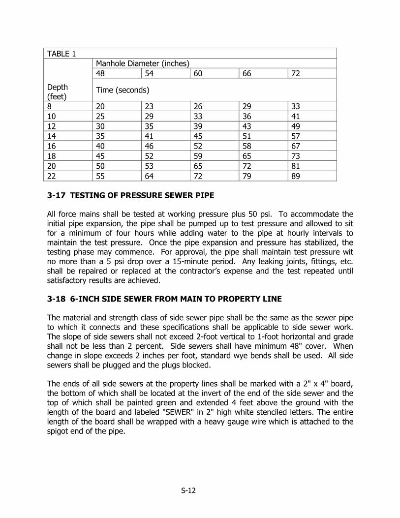
The test head shall be placed at the top of the manhole in accordance to the manufacturer's recommendations. A vacuum of 10 inches of mercury shall be drawn on the manhole, the valve on the vacuum line of the test head closed, and the vacuum pump shut off. The time shall be measured for the vacuum to drop to 9 inches of mercury. The manhole shall pass if the time it takes the mercury to drop from 10 inches of mercury to 9 inches of mercury meets or exceeds the values indicated in Table 1 below.
S-12
TABLE 1
Depth (feet)
Manhole Diameter (inches)
48 54 60 66 72
Time (seconds)
8 20 23 26 29 33
10 25 29 33 36 41
12 30 35 39 43 49
14 35 41 45 51 57
16 40 46 52 58 67
18 45 52 59 65 73
20 50 53 65 72 81
22 55 64 72 79 89
3-17 TESTING OF PRESSURE SEWER PIPE
All force mains shall be tested at working pressure plus 50 psi. To accommodate the initial pipe expansion, the pipe shall be pumped up to test pressure and allowed to sit for a minimum of four hours while adding water to the pipe at hourly intervals to maintain the test pressure. Once the pipe expansion and pressure has stabilized, the testing phase may commence. For approval, the pipe shall maintain test pressure wit no more than a 5 psi drop over a 15-minute period. Any leaking joints, fittings, etc. shall be repaired or replaced at the contractor’s expense and the test repeated until satisfactory results are achieved.
3-18 6-INCH SIDE SEWER FROM MAIN TO PROPERTY LINE
The material and strength class of side sewer pipe shall be the same as the sewer pipe to which it connects and these specifications shall be applicable to side sewer work. The slope of side sewers shall not exceed 2-foot vertical to 1-foot horizontal and grade shall not be less than 2 percent. Side sewers shall have minimum 48" cover. When change in slope exceeds 2 inches per foot, standard wye bends shall be used. All side sewers shall be plugged and the plugs blocked.
The ends of all side sewers at the property lines shall be marked with a 2" x 4" board, the bottom of which shall be located at the invert of the end of the side sewer and the top of which shall be painted green and extended 4 feet above the ground with the length of the board and labeled "SEWER" in 2" high white stenciled letters. The entire length of the board shall be wrapped with a heavy gauge wire which is attached to the spigot end of the pipe.

S-13
3-19 CONNECTION TO THE EXISTING SYSTEM
No connections shall be made to the existing sewer system without the presence of the District. Written application for connection shall be made to the District for connection, and the connection shall be made at a time agreed upon with the District.
Connections to existing manholes shall be made as follows: If the manhole is "live," manhole channel shall be tightly covered, prior to breaking into the manhole wall, to prevent debris from entering the sewer line. Immediately after the connection is made, the new pipe shall be plugged. The plug shall not be removed without permission of the District. If the existing manhole is not "live," a plug shall be installed in the downstream or discharge pipe of the existing manhole in addition to the above.
Connections of new mains to existing sewer lines shall be made as follows: A new manhole shall be placed over the existing line. The manhole shall be precast 54-inch diameter except that the base slab shall be cast in place. The new connection shall be plugged and blocked and the existing sewer pipe shall not be opened without the permission of the District.
Connections of side sewers to an existing sewer line shall be made as follows, or as directed by the District Engineer.
A) For ductile iron pipe, the connection shall be made with a stainless steel, or stainless steel with ductile iron flange, tapping tee, Romac model "SST" or equal. A FL by MJ adapter is required.
B) For PVC or AC pipe, the connection shall be made with a sewer saddle, Romac style "CB" or equal.
The existing sewer pipe shall be cut or drilled to give a smooth symmetrical opening of the proper size. Each connection shall be bedded with a 4-inch thick concrete pad in place to the lower quadrant of the pipe barrel. Unsuitable foundation material shall be overexcavated and replaced with bedding material.
3-20 TRAFFIC CONTROL
All traffic control shall be per the Manual of Uniform Traffic Control Devices, and/or agency of jurisdiction. During construction, traffic shall not be delayed for more than 5 minutes unless previously approved by the District and the agency of jurisdiction.
3-21 T.V. INSPECTION
Prior to acceptance, all pipe shall be flushed and T.V. inspected at contractors expense. Contractor shall notify the District 48 hours pior to the need for flushing and T.V. inspection. All manholes must be channeled, the sewer system completed and the roadway subbase (ATB or 2" class B asphalt) installed before the T.V. inspection. Sewer dye, Norlab or approved equal, shall be introduced into the system prior to the T.V. inspection, if required. The T.V. camera must be pulled through the pipe without
S-14
use of a hydraulic flushing nozzle. A video disk of this inspection shall be submitted to the District along with a completed certified report by the Contractor. Video must start at the downstream manhole and proceed upstream against the flow. All defects revealed by the T.V. inspection shall be repaired by the Contractor to the District's satisfaction. Any pipe or sanitary manhole channel with a sag that creates a standing water depth of 1/4-inch may be rejected by the District (No sag of 1/2-inch or greater will be accepted.) Depending on the severity and extent of the defects, the District may require that the entire pipe run be relayed.
3-22 SIDE SEWERS
A side sewer permit will be required from the District before installation of side sewers. Commercial waste discharge from fixtures and equipment that may contain grease, including but not limited to, scullery sinks, pot and pan sinks, dishwashers, soup kettles, and floor drains located in areas where grease containing materials may exist, will require a grease interceptor prior to entering the sanitary sewer system. Commercial establishments that may discharge oil into the sanitary sewer system will require an oil separator prior to entering the sewer system.
3-23 CATCH BASIN INSERTS
All catch basins located along the project shall have a sediment catch basin insert
installed that is in compliance with the local jurisdiction. The insert shall have a built-in
high-flow relief system. The insert retrieval system must allow removal of the insert
without spilling the collected material. Inserts are to be cleaned and replaced by
Contractor per manufacturer's recommendations or by District direction.