Sewer Bedding Standard Installation Method
8
-
Upload
sana-ullah -
Category
Documents
-
view
223 -
download
0
Transcript of Sewer Bedding Standard Installation Method
8/13/2019 Sewer Bedding Standard Installation Method
http://slidepdf.com/reader/full/sewer-bedding-standard-installation-method 1/8

8/13/2019 Sewer Bedding Standard Installation Method
http://slidepdf.com/reader/full/sewer-bedding-standard-installation-method 2/8
Indirect Design
Comparison of thestructural strengthof the pipe (Three-Edge-BearingTest) to the fieldsupportingstrength of aburied pipe.
Direct Design
The design of pipein the installedcondition. Themagnitude anddistributionof loads aredetermined andthe physicalproperties
necessary tosupport thoseloads arecalculated. Formore informationregardingconcrete pipedesign refer to theACPA’s ConcretePipe DesignManual.
Since the early1920’s, designersof buried pipe havespecified embedmentdetails based onClass A, B, C and Dbeddings developedby Marston &Spangler at Iowa StateUniversity. Many ofthe design practices incurrent use are basedon this research.
By the 1970’s,ACPA membersrealized that newanalytical knowledgeand field experiencewere availablethat could lead toimprovements in
understanding thestructural behaviorof buried pipe in itsinstalled conditionand thus, lead toimprovements indesign practice forburied concrete pipe.In view of this, ACPAinstituted a long-rangeresearch program
with the overallobjective of evaluatingthe performance ofconcrete pipe-soil
installations and improving design practice forpipe-soil installations. The structural behaviorof these installations was examined usingstate-of-the-art analytical tools of structuraland geotechnical engineering and computerscience and by comparing the results of
analytical studies with observations andmeasurements on prototype pipe inboth three-edge bearing tests and fieldinstallations.
These research results provide thebasis for a more advanced designpractice for pipe-soil installations basedon direct design of the pipe for itsinstalled conditions. They also providethe basis for recommending standardizedinstallation types that differ significantlyfrom those originally developed byMarston and Spangler and currently usedin indirect design practice.
Essentially, the same installation
types are defined for both trench andembankment installations. TheseStandard Installations have severaladvantages over Class A, B, C andD beddings because of the followingconsiderations of practical construction:
• A flat foundation and beddingsimplifies construction.
• Bedding cannot be shaped withinsufficient tolerance to provide uniformsupport to the outside of the pipe over
a shaped bedding angle.• Embedment soil cannot be compacted
in the lower haunch area up to about40 degrees from the invert.
• Standard Installations should permitthe use of a range of embedment soilsfrom the best quality granular soilsthat are easily compacted to variouslesser quality soils that may be readilyavailable at a site. They should alsoinclude the option to use many native
soils without compaction around thepipe for bedding, embedment andbackfill.
• Requirements for compaction with,or without, the use of high-qualityembedment soils should be limited tothose zones around the pipe wherethe embedment provides beneficialvertical or lateral support to the pipe.

8/13/2019 Sewer Bedding Standard Installation Method
http://slidepdf.com/reader/full/sewer-bedding-standard-installation-method 3/8
These new Standard Installations identifyfour principal zones (which are criticalto the pipe-soil system) surrounding thelower half of the pipe. The four zones
– middle bedding, outer bedding, haunchand lower side – are shown in Figures1 and 2 for trench and embankmentinstallations. The type of material (basedon soil characteristics) and level ofcompaction varies with the installationtype, i.e., 1, 2, 3, or 4, and the materialutilized in construction of these importantzones.
Installation – Type 4 Type 4 is intended
for installations where the most costeffective design approach is to specifyminimal requirements for soil type andcompaction, together with a pipe havingsufficient strength to safely resist theincreased structural effects that resultfrom using low quality soils. Thus, Type 4has little or no requirement for control ofcompaction and type of placed soil usedin the bedding and haunch areas, exceptif silty clay soils are used in the haunch
and outer bedding zones, they must becompacted. It is desirable to scarify(loosen) hard native soils before placingpipe.
Installation – Type 3 Type 3 permits theuse of soils in the haunch and beddingzones having easily attained compactionrequirements, justifying less stringentinspection requirements with granular
and some native soils. Silty clays maybe used in the haunch zone if adequatelycompacted. In addition to the foundationsimilar to Type 4, a bedding layer with aminimum thickness of 3 inches is requiredto avoid placing the pipe directly on hardor variable subgrade.
Installation – Type 2 Type 2 is a standardinstallation where certain native soils are
permitted to be used with proper compactionin the haunch and bedding zones. Adequatelycompacted native silty granular soils or selectgranular soils may be used in the haunch and
outer bedding zones. This is intended to allowthe use of soil frequently found at a site. Anynatural soil adjacent to the pipe should havea firmness equivalent to the placed soils.Foundation and bedding requirements aresimilar to Type 3.
Installation – Type 1 Type 1 requires wellcompacted, select granular soil to be placedin the haunch and bedding zones. Thestructural design of the pipe section then takes
advantage of the support provided by this highquality soil envelope, making this installationoften the most cost effective for pipe 60 inchesin diameter and larger in deep fills.
8/13/2019 Sewer Bedding Standard Installation Method
http://slidepdf.com/reader/full/sewer-bedding-standard-installation-method 4/8
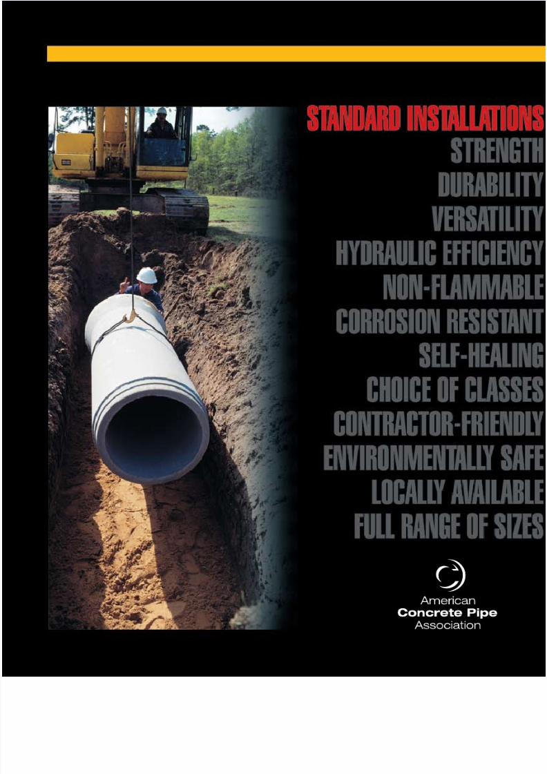
Relative ComparisonEmbedment vs Pipe Cost
Installation Type
Embedment CostPipe Cost
1 2 3 4
Beneficial CharacteristicsVersatile - One can choose between installation types and pipe strengths (classes) to suitspecific site conditions and budgetary constraints. The four standard installations can be
used to optimize the total installed cost by evaluation of the ratio of pipe cost to backfillmaterial cost.
Conservative - Analyses are based on the worst case (embankment) loadings, voids inthe haunch zone, the greatest predicted loads, and measurable requirements that moreaccurately assess long-term performance of the system.
Quantifiable – Definite and measurable levels of acceptance are prescribed, which providesbetter direction for the designer and the contractor.
Category I
Category II
Category III
Category IVbut notallowed
for haunchor bedding
Soil
Representative Soil Types Percent Compaction
StandardProctor
ModifiedProctor
USCSASTM D 2487
AASHTOM 145
Clean, course grainedsoils: SW, SP, GW,
GP or any soilbeginning with one
of those symbols with12% or less passing
a #200 sieve
Course grained soilswith fines: GM, GC,SM, SC or any soilbeginning with oneof these symbols,
containing more than12% passing a
#200 sieve;Sandy or gravelly fine–grained soils: CL, ML,
(or CL-ML, CL/ML,ML/CL) with 30%or more retainedon a #200 sieve
Fine-grained soils: CL,ML, (or CL-ML, CL/ML,
ML/CL) with less than 30%retained on a #200 sieve
MH, CH, OL,OH, PT
A-1, A-3
A-2-4, A-2-5,A-2-6: or A-4or A-6 soils with
30% or moreretained on a#200 sieve
A-2-7: or A-4 or A-6 with less than30% retained on a
#200 sieve
A-5, A-7
100959085
100959085
100959085
1009590
95908580
95908580
90858075
908580
NOTE 1: Compaction Specifications:Standard proctor density – AASHTO T 99, T 310, or Test Methods D 698Modified proctor density – AASHTO T 180 or Test Methods D 1557
Equivalent USCS and AASHTOSoil Classifications for Soil Designations
8/13/2019 Sewer Bedding Standard Installation Method
http://slidepdf.com/reader/full/sewer-bedding-standard-installation-method 5/8
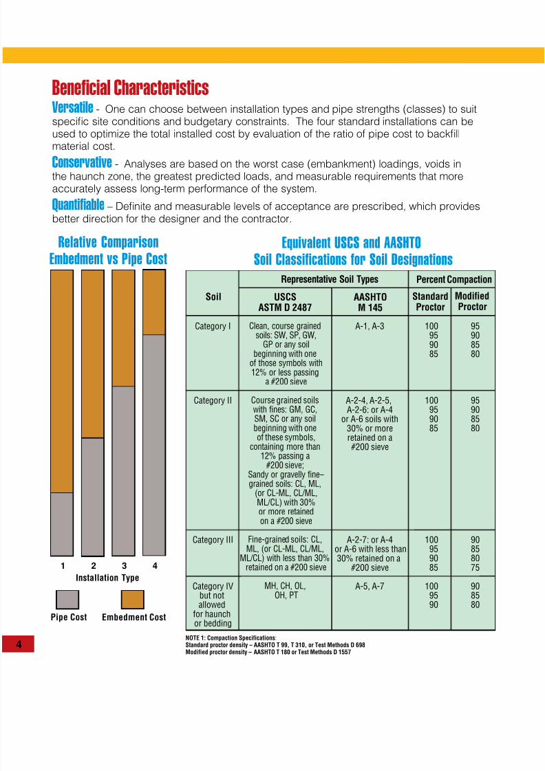
Do
See Note 1
Do (Min.)
Do /3
Di
Middle Bedding looselyplaced uncompactedbedding except for Type 4
Note 1: Clearance between pipe and trench wall shall be adequate to enable specific compaction, but not less than Do /6.
Outer bedding material andcompaction each side, same
requirements as haunchFoundation
Bedding
H
Haunch
Lower Side
Overfill or Backfill - Category I, II, III
Haunch andInstallation Type Bedding Thickness Outer Bedding Lower Side
Type 1
Type 2
Type 3
Type 4
D0 /24 minimum; not less than 3 in. If rockfoundation, use D0 /12 minimum; not less than 6 in.
D0 /24 minimum; not less than 3 in. If rockfoundation, use D0 /12 minimum; not less than 6 in.
D0 /24 minimum; not less than 3 in. If rockfoundation, use D0 /12 minimum; not less than 6 in.
No bedding required, except if rock foundation, useD0 /12 minimum; not less than 6 in.
95% Category I
90% Category I or95% Category II
85% Category I,90% Category II, or
95% Category III
No compaction required,except if Category III,use 85% Category III
Undisturbed natural soil with firmness equivalentto the following placed soils: 90% Category I,95% Category II, or 100% Category III, orembankment to the same requirements
Undisturbed natural soil with firmness equivalentto the following placed soils: 85% Category I,90% Category II, or 95% Category III, orembankment to the same requirements
Undisturbed natural soil with firmness equivalentto the following placed soils: 85% Category I,90% Category II, or 95% Category III, orembankment to the same requirements
No compaction required, except if Category III,use 85% Category III
Note 1. Compaction and soil symbols, i.e. 95% Category I, refer to a soil material category with a minimum standard proctor density. See Table on page 4 for
equivalent modified proctor values and soil types.
Note 2. When the trench width specified must be exceeded, the owner shall be notified.
Note 3. The trench width shall be wider than shown if required for adequate space to attain the specified compaction in the haunch and bedding zones.
Note 4. Embankment loading shall be used when trench walls consist of embankment unless a geotechnical analysis is made and the soil in the trench walls is
compacted to a higher level than the soil in the backfill zone.
Note 5. Required bedding thickness is the thickness of the bedding prior to placement of the pipe.
Note 6. “Dumped” material without additional compactive effort will not provide the design haunch support required for Type 1 and 2 installations and it
should be checked for Type 3 installations.
SOIL AND MINIMUM COMPACTION REQUIREMENTS
Figure 1. Standard Trench Installation
8/13/2019 Sewer Bedding Standard Installation Method
http://slidepdf.com/reader/full/sewer-bedding-standard-installation-method 6/8
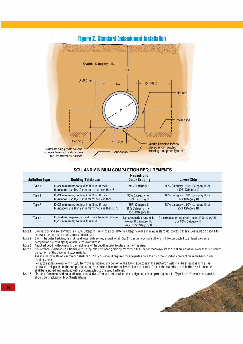
Do
Do /6 (min.)Do (Min.)
Do /3
Di
Middle Bedding looselyplaced uncompactedbedding except for Type 4Foundation
Bedding
H
Haunch
Lower Side
Overfill - Category I, II, III
Outer bedding material andcompaction each side, same
requirements as haunch
Figure 2. Standard Embankment Installation
Haunch and
Installation Type Bedding Thickness Outer Bedding Lower SideType 1
Type 2
Type 3
Type 4
D0 /24 minimum; not less than 3 in. If rockfoundation, use D0 /12 minimum; not less than 6 in.
D0 /24 minimum; not less than 3 in. If rockfoundation, use D0 /12 minimum; not less than 6 i
D0 /24 minimum; not less than 3 in. If rockfoundation, use D0 /12 minimum; not less than 6 in.
No bedding required, except if rock foundation, useD0 /12 minimum; not less than 6 in.
95% Category I
90% Category I or95% Category II
85% Category I,90% Category II, or
95% Category III
No compaction required,except if Category III,use 85% Category III
90% Category I, 95% Category II, or100% Category III
85% Category I, 90% Category II, or95% Category III
85% Category I, 90% Category II, or95% Category III
No compaction required, except if Category III,use 85% Category III
Note 1. Compaction and soil symbols, i.e. 95% Category I, refer to a soil material category with a minimum standard proctor density. See Table on page 4 forequivalent modified proctor values and soil types.
Note 2. Soil in the outer bedding, haunch, and lower side zones, except within DO /3 from the pipe springline, shall be compacted to at least the same
compaction as the majority of soil in the overfill zone.Note 3. Required bedding thickness is the thickness of the bedding prior to placement of the pipe.Note 4. A subtrench is defined as a trench with its top below finished grade by more than 0.1H or, for roadways, its top is at an elevation lower than 1 ft below
the bottom of the pavement base material. The minimum width of a subtrench shall be 1.33 DO or wider, if required for adequate space to attain the specified compaction in the haunch and
bedding zones. For subtrenches, except within DO /3 from the springline, any portion of the lower side zone in the subtrench wall shall be at least as firm as an
equivalent soil placed to the compaction requirements specified for the lower side zone and as firm as the majority of soil in the overfill zone, or itshall be removed and replaced with soil compacted to the specified level.
Note 5. “Dumped” material without additional compactive effort will not provided the design haunch support required for Type 1 and 2 installations and itshould be checked for Type 3 installations.
SOIL AND MINIMUM COMPACTION REQUIREMENTS

8/13/2019 Sewer Bedding Standard Installation Method
http://slidepdf.com/reader/full/sewer-bedding-standard-installation-method 7/8
STANDARDS: • ASTM C 1479 Installation of Precast
Concrete Sewer, Storm Drain, and Culvert
Pipe Using Standard Installations • AASHTO Standard Specifications forHighway Bridges
• ASCE 15 Direct Design of Buried PrecastConcrete Pipe Using Standard Installations(SIDD)
REFERENCES: • Concrete Pipe Technology Handbook • Concrete Pipe Design Manual
• Concrete Pipe Handbook • Design Data 40 (American Concrete Pipe Association
Publications)

8/13/2019 Sewer Bedding Standard Installation Method
http://slidepdf.com/reader/full/sewer-bedding-standard-installation-method 8/8
ACPA’S WEBSITE PROVIDES WEALTH OF ON-LINE INFORMATION
© ACPA 2007 (01/07) 5M Resource 07-126
1303 West Walnut Lane, Suite 305 • Irving, Texas 75038-3008 • Phone 972-506-7216 • Fax 972-506-7682 • [email protected]
The American Concrete Pipe Association’s website, www.
concrete-pipe.org, has become one of the most popular Internet
websites for design engineers and specifiers of drainage pipe
products – and for good reason! The site provides visitors with a
wealth of information on precast concrete pipe products. Information
available includes loads and supporting strengths, hydraulics,
installation standards, fill height tables, latest design software,
and installation guidelines. The popular Concrete Pipe Design
Manual is on-line and available for order in both hard copy and CD
format. The website also serves as a “gateway” to access member
locations, related associations – even Internet addresses for state
DOT websites. Visitors can also purchase additional resources
through ACPA’s Resource Center.
If you haven’t already, you will want to add ACPA’s website to
your “favorite” list on your browser, so you can access complete
information on precast concrete pipe products for culverts, storm
drains and sanitary sewer applications.
s h a r e t h i s s i t e • m a k e t h i s y o u r h o m e p a g e • c o n t a c t u s • s i t e m a p • h e l p • s e a r c h ASSOCIATION INFORMATION
EDUCATION
GOVERNMENT RELATIONS
MARKETING INFORMATION
MEETINGS AND EVENTS
MEMBERSHIP LOCATION
MEMBERS ONLY AREA
Q-CAST
RESOURCES
SAFETY AND ENVIROMENT
TECHNICAL INFORMATION