User and installation manual
18
ArcelorMittal INERD Innovation for earthquake-resistant design User’s manual Global Research and Development Esch Version 1.0.0 June 2009
-
Upload
teodorabogdan -
Category
Documents
-
view
232 -
download
0
Transcript of User and installation manual

8/7/2019 User and installation manual
http://slidepdf.com/reader/full/user-and-installation-manual 1/18
ArcelorMittal INERD
Innovation for earthquake-resistant design
User’s manual
Global Research andDevelopment Esch
Version 1.0.0 June 2009
8/7/2019 User and installation manual
http://slidepdf.com/reader/full/user-and-installation-manual 2/18
ArcelorMittal INERD – version 1.0.0
2
INERD – USER’S MANUEL
CONTENTS
1 INTRODUCTION_______________________________________________________3
1.1 Purpose ___________________________________________________________ 31.2 Required configuration _______________________________________________ 3
1.3 Installation procedure ________________________________________________ 3
2 DESCRIPTION OF THE GRAPHICAL USER INTERFACE ____________________7
2.1 General ___________________________________________________________ 7
2.1.1 Description of the main window ____________________________________ 7
2.1.2 Data and results files management __________________________________8
2.1.3 Units management_______________________________________________ 9
2.1.4 Module "Start full data check" _____________________________________ 9
2.1.5 Module "Start calculation to perform all design checks" _________________9
2.2 "Menu" bar _______________________________________________________10
2.2.1 File__________________________________________________________ 102.2.2 Edit _________________________________________________________10
2.2.3 View ________________________________________________________10
2.2.4 Calculation ___________________________________________________ 10
2.2.5 Tools ________________________________________________________11
2.2.6 Windows _____________________________________________________11
2.2.7 Help _________________________________________________________12
2.3 Description of the tab sheets __________________________________________12
2.3.1 Project Info ___________________________________________________ 12
2.3.2 Column section ________________________________________________ 12
2.3.3 Inerd profile___________________________________________________ 13
2.3.4 Layout _______________________________________________________14
2.3.5 Loading ______________________________________________________15
2.3.6 Results _______________________________________________________15
2.4 Graphical area _____________________________________________________17
2.5 Warning/error table _________________________________________________ 17
3 Description of the design procedures _______________________________________ 17
4 References____________________________________________________________ 18
8/7/2019 User and installation manual
http://slidepdf.com/reader/full/user-and-installation-manual 3/18
ArcelorMittal INERD – version 1.0.0
3
1 INTRODUCTION
1.1 Purpose
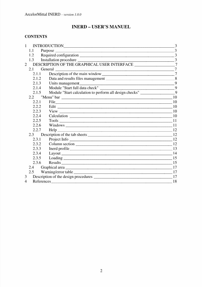
The INERD concept is an additional constructive system independent of analysis and design
that can be applied to reinforced concrete frame structures. It intends to bring to the structure
the robustness required by Eurocode 1 [prEN 1991-1-7: 2004 §1.5.14], i.e. “the ability of the
structure to withstand events like fire, explosions, impact or the consequences of human error,
without being damaged to an extent disproportionate to the original cause”. The particular
objective of the INERD system is to avoid progressive failure, i.e. a chain in which a local
failure at the bottom storey generates a global failure out of proportion with the original local
problem.
after earthquake
plastichinges
soft storey
More precisely, the INERD concept for concrete frames consists in placing a steel profile
inside the reinforced concrete columns of the ground storey of the building. This profile is not
considered in the structural design, which is carried out as usual for RC structures, and is
assumed to act as a safety belt activated only in case of unexpected deficiencies of the
concrete under earthquake action, due for example to presence of infill panels, uncertainties
on the seismic action and in particular on its vertical component, uncertainties on the actualconcrete properties.
The essential purpose of the INERD software is to help the designer for the selection of the
most appropriate profile to be placed inside the concrete columns of the bottom storey in
order to prevent the occurrence of soft storey mechanisms.
1.2 Required configuration
The software is designed for Microsoft Windows. The software has been tested on Windows
XP. It should also run under Windows 2000 and Windows Vista, but this is not assured. To
install and run the software 512 MB memory and 15 MB hard disk space is required.
The software is developed for the Microsoft .NET framework. If the .NET framework is notinstalled yet, this will be done automatically by the setup procedure. In this case additional
280 MB disk space must be available to install the .NET framework.
Finally the Adobe Reader is required to view the results of the calculation. The Adobe Reader
is not provided with the installation file, it can be downloaded for free from the Adobe
website: www.adobe.com/reader.
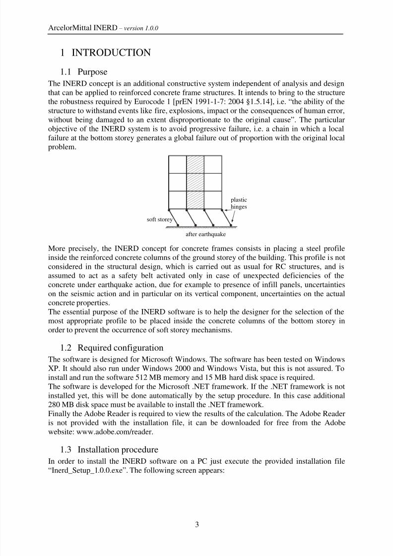
1.3 Installation procedure
In order to install the INERD software on a PC just execute the provided installation file
“Inerd_Setup_1.0.0.exe”. The following screen appears:
8/7/2019 User and installation manual
http://slidepdf.com/reader/full/user-and-installation-manual 4/18

8/7/2019 User and installation manual
http://slidepdf.com/reader/full/user-and-installation-manual 5/18
ArcelorMittal INERD – version 1.0.0
5
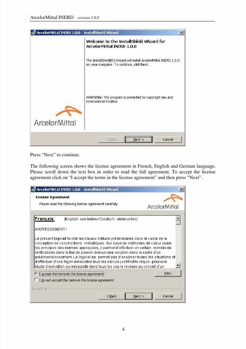
On this screen you can specify the installation folder. Press “Next” to continue.
Now click “Install” to start the installation process.

8/7/2019 User and installation manual
http://slidepdf.com/reader/full/user-and-installation-manual 6/18
ArcelorMittal INERD – version 1.0.0
6
Press “Finish” to quit the installation procedure.
INERD is now installed on your PC.
1.4 Launch INERD
To launch the INERD software click on the INERD icon on your desktop, or select“StartProgram FilesArcelorMittalINERDINERD 1.0.0”.
1.5 Examples
You can find some example files in the folder “<INERD installation folder>\Examples\”
(In a typical installation this folder would be “C:\Program files\ArcelorMittal\INERD\
Examples\”. For guidance to open INERD files reference is made to section 2.2.1)

8/7/2019 User and installation manual
http://slidepdf.com/reader/full/user-and-installation-manual 7/18
ArcelorMittal INERD – version 1.0.0
7
2 DESCRIPTION OF THE GRAPHICAL USER INTERFACE
2.1 General
2.1.1 Description of the main windowThe general layout of the main screen is similar to most software’s in the Windows
environment and includes from the top to the bottom:
- Title bar,
- Menu bar,
- Tool bar,
- Set of tab-sheets,
- Graphical area,
- Warning/errors table,
- Status bar.
"Menu" bar contains:
- "File" menu,
- "Edit" menu,
- "View" menu,
- "Calculation" menu,
- "Tools" menu,

8/7/2019 User and installation manual
http://slidepdf.com/reader/full/user-and-installation-manual 8/18
ArcelorMittal INERD – version 1.0.0
8
- "Windows" menu,
- "Help" menu.
"Tool" bar includes the classical Windows buttons (New, Open, Save, Print, Cut, Copy, Paste,
Undo, Redo) and 2 specific Inerd buttons activating respectively the following modules:
- Module "Start full data check" ,
- Module "Start calculation to perform all design checks" .
Note that access to the module "Start full data check" is not possible when the option
"Optimise profile" is activated in the tab-sheet "Results" (See later for more information).
The different tab-sheets are:
- "Project Info",
-
"Column section",- "Inerd profile",
- "Layout",
- "Loading",
- "Results".
2.1.2 Data and results files management
When saving the project ("save" button or "save as…" in the "file" menu), all project data are
stored in a *.Ird file.
During data introduction and after processing, available data and results can be viewed and/or
printed through the "outpout" file (adobe Pdf format). This file can be created through "File"

8/7/2019 User and installation manual
http://slidepdf.com/reader/full/user-and-installation-manual 9/18
ArcelorMittal INERD – version 1.0.0
9
menu ("Output"), through tab-sheet "Results" ("Show output") or by clicking "Output" button
in the tool bar.
A scroll list at the bottom of the "Output" window allows defining:
- "Output level"
o "Graphics & System & Detailed results"o "Graphics & System & Results"
o "Graphics & System"
o "Graphics"
- "Output settings"
2.1.3 Units management
The software allows the following choice of force and length units.
The force units are:- Newton (N),
- kiloNewton (kN),
- megaNewton (MN).
The length units are:
- millimeter (mm),
- centimeter (cm),
- meter (m).
When units are changed, values from data sheets and on the drawings (when displayed) are
automatically updated according to the new unit definition.
2.1.4 Module "Start full data check"
This module aims at checking all data given by the user according to the rules described in the
help document "General summary of the technological verifications" based on Eurocode 2
and 8 rules.
2.1.5 Module "Start calculation to perform all design checks"
This module has two possible uses:
a. Check whether a given profile fulfils all requirements in terms of
- INERD design conditions
- Profile anchorage check
b. Choose the optimum profile to be used for a given concrete configuration
It provides also additional outputs (anchorage length of the profile, spacing of stirrups in the
anchorage zone and thickness of the end plate).
8/7/2019 User and installation manual
http://slidepdf.com/reader/full/user-and-installation-manual 10/18
ArcelorMittal INERD – version 1.0.0
10
2.2 "Menu" bar
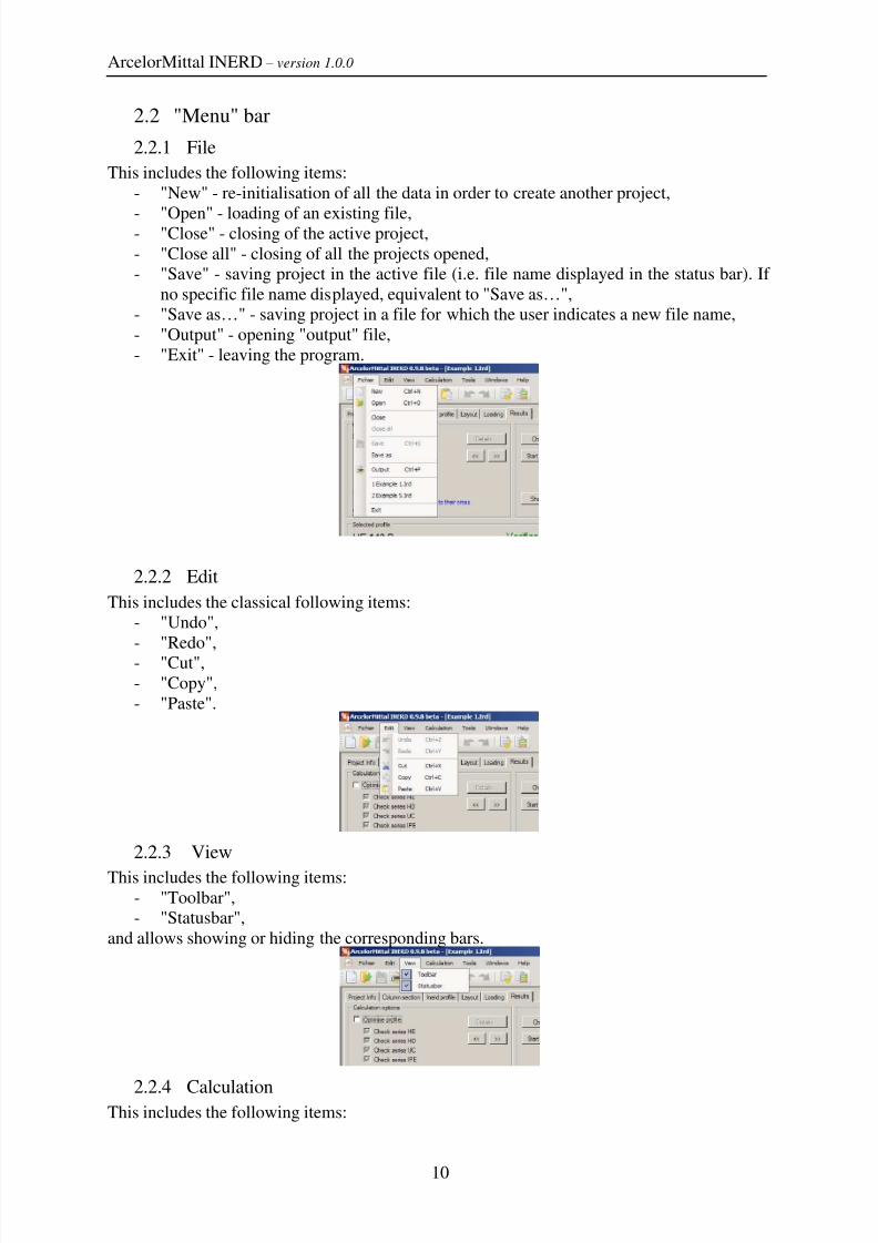
2.2.1 File
This includes the following items:
- "New" - re-initialisation of all the data in order to create another project,
- "Open" - loading of an existing file,- "Close" - closing of the active project,
- "Close all" - closing of all the projects opened,
- "Save" - saving project in the active file (i.e. file name displayed in the status bar). If
no specific file name displayed, equivalent to "Save as…",
- "Save as…" - saving project in a file for which the user indicates a new file name,
- "Output" - opening "output" file,
- "Exit" - leaving the program.
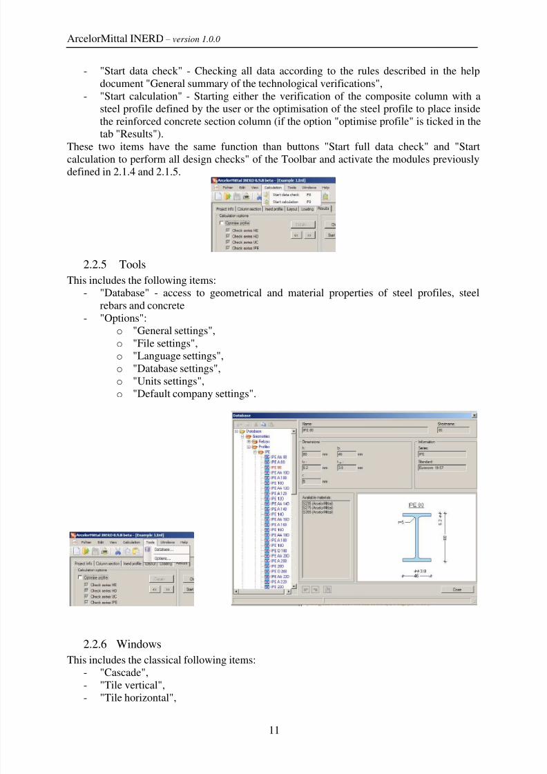
2.2.2 Edit
This includes the classical following items:
- "Undo",
- "Redo",
- "Cut",
- "Copy",
- "Paste".
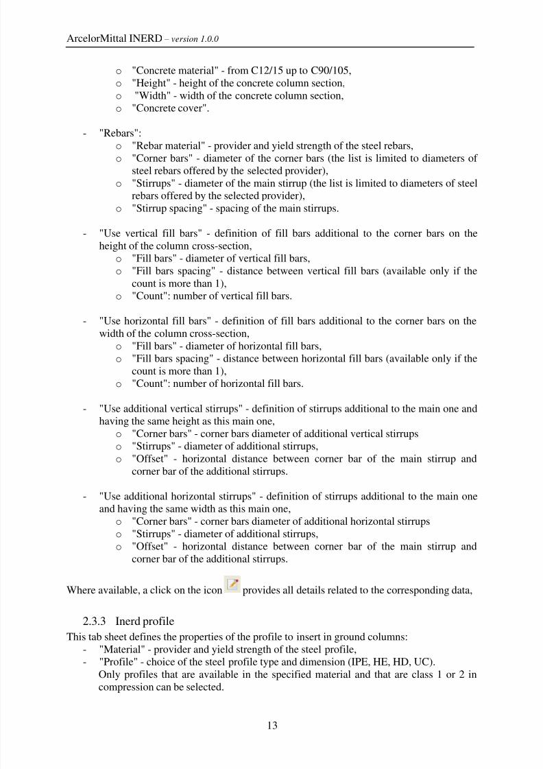
2.2.3 View
This includes the following items:- "Toolbar",
- "Statusbar",
and allows showing or hiding the corresponding bars.
2.2.4 CalculationThis includes the following items:
8/7/2019 User and installation manual
http://slidepdf.com/reader/full/user-and-installation-manual 11/18
ArcelorMittal INERD – version 1.0.0
11
- "Start data check" - Checking all data according to the rules described in the help
document "General summary of the technological verifications",
- "Start calculation" - Starting either the verification of the composite column with a
steel profile defined by the user or the optimisation of the steel profile to place inside
the reinforced concrete section column (if the option "optimise profile" is ticked in the
tab "Results").These two items have the same function than buttons "Start full data check" and "Start
calculation to perform all design checks" of the Toolbar and activate the modules previously
defined in 2.1.4 and 2.1.5.
2.2.5 Tools
This includes the following items:
- "Database" - access to geometrical and material properties of steel profiles, steel
rebars and concrete
- "Options":
o "General settings",
o "File settings",
o "Language settings",
o "Database settings",
o "Units settings",
o "Default company settings".
2.2.6 Windows
This includes the classical following items:
-
"Cascade",- "Tile vertical",
- "Tile horizontal",

8/7/2019 User and installation manual
http://slidepdf.com/reader/full/user-and-installation-manual 12/18
ArcelorMittal INERD – version 1.0.0
12
- Names of the files opened.
The first 3 items can only be used when more than one project is opened.
2.2.7 Help
It includes the following items:- User manual
- "Documents" - access to background information on the concept and on the software
(Pdf format):
The INERD concept,
General technical background of the software,
Anchorage of the steel profile in usual conditions,
Anchorage of the steel profile on a foundation,
Practical design of transverse reinforcement,
End-plates,
General summary of the technological verifications.
- "About" - version number and information on the technical partners
2.3 Description of the tab sheets
2.3.1 Project Info
This tab sheet includes the following items:
- "Client information" - definition of client name and address,
- "Project information" - description of the project,
- "Company information" - definition of company name, address and designer.
2.3.2 Column section
This tab sheet includes the following items:- "Concrete section":
8/7/2019 User and installation manual
http://slidepdf.com/reader/full/user-and-installation-manual 13/18
ArcelorMittal INERD – version 1.0.0
13
o "Concrete material" - from C12/15 up to C90/105,
o "Height" - height of the concrete column section,
o "Width" - width of the concrete column section,
o "Concrete cover".
- "Rebars":o "Rebar material" - provider and yield strength of the steel rebars,
o "Corner bars" - diameter of the corner bars (the list is limited to diameters of
steel rebars offered by the selected provider),
o "Stirrups" - diameter of the main stirrup (the list is limited to diameters of steel
rebars offered by the selected provider),
o "Stirrup spacing" - spacing of the main stirrups.
- "Use vertical fill bars" - definition of fill bars additional to the corner bars on the
height of the column cross-section,
o "Fill bars" - diameter of vertical fill bars,
o "Fill bars spacing" - distance between vertical fill bars (available only if thecount is more than 1),
o "Count": number of vertical fill bars.
- "Use horizontal fill bars" - definition of fill bars additional to the corner bars on the
width of the column cross-section,
o "Fill bars" - diameter of horizontal fill bars,
o "Fill bars spacing" - distance between horizontal fill bars (available only if the
count is more than 1),
o "Count": number of horizontal fill bars.
- "Use additional vertical stirrups" - definition of stirrups additional to the main one and
having the same height as this main one,
o "Corner bars" - corner bars diameter of additional vertical stirrups
o "Stirrups" - diameter of additional stirrups,
o "Offset" - horizontal distance between corner bar of the main stirrup and
corner bar of the additional stirrups.
- "Use additional horizontal stirrups" - definition of stirrups additional to the main one
and having the same width as this main one,
o "Corner bars" - corner bars diameter of additional horizontal stirrups
o "Stirrups" - diameter of additional stirrups,
o "Offset" - horizontal distance between corner bar of the main stirrup and
corner bar of the additional stirrups.
Where available, a click on the icon provides all details related to the corresponding data,
2.3.3 Inerd profile
This tab sheet defines the properties of the profile to insert in ground columns:
- "Material" - provider and yield strength of the steel profile,
- "Profile" - choice of the steel profile type and dimension (IPE, HE, HD, UC).
Only profiles that are available in the specified material and that are class 1 or 2 incompression can be selected.
8/7/2019 User and installation manual
http://slidepdf.com/reader/full/user-and-installation-manual 14/18
ArcelorMittal INERD – version 1.0.0
14
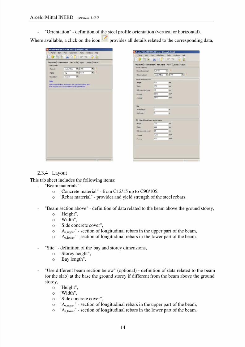
- "Orientation" - definition of the steel profile orientation (vertical or horizontal).
Where available, a click on the icon provides all details related to the corresponding data,
2.3.4 Layout
This tab sheet includes the following items:- "Beam materials":
o "Concrete material" - from C12/15 up to C90/105,
o "Rebar material" - provider and yield strength of the steel rebars.
- "Beam section above" - definition of data related to the beam above the ground storey,
o "Height",
o "Width",
o "Side concrete cover",
o "As,upper" - section of longitudinal rebars in the upper part of the beam,
o "As,lower" - section of longitudinal rebars in the lower part of the beam.
- "Site" - definition of the bay and storey dimensions,
o "Storey height",
o "Bay length".
- "Use different beam section below" (optional) - definition of data related to the beam
(or the slab) at the base the ground storey if different from the beam above the ground
storey,
o "Height",
o "Width",
o "Side concrete cover",
o "As,upper" - section of longitudinal rebars in the upper part of the beam,o "As,lower" - section of longitudinal rebars in the lower part of the beam.
8/7/2019 User and installation manual
http://slidepdf.com/reader/full/user-and-installation-manual 15/18
ArcelorMittal INERD – version 1.0.0
15
Where available, a click on the icon provides all details related to the corresponding data,
2.3.5 Loading
This tab sheet includes the following items:
- "Loading"o "NEd" - Design normal force in the column corresponding to gravity loads such
as considered in the seismic load combination.
The value of the design axial force EdN is given directly by the user. This
value should be evaluated as follows:
EdN is the compression force in a 1st
storey column due to the non seismic
actions participating in the seismic load combination. It may be computed
based on a weight W calculated as: W = kj Ei kiG ψ Q+ ⋅∑ ∑
Where Gkj are the dead loads and Qki are the variable loads.
The coefficient ψ Ei,used to estimate a likely value of service loads, is computed
as: Ei 2iψ ϕ ψ = ⋅
Values of ψ 2i (quasi-permanent combination coefficient as given by Eurocode1) and φ (reduction factor given by Eurocode 8) are summarized in Table 1 for
usual situations. For example, in an office buildings in which all levels are used
independently: Ei 2i 0,5 0,3 0,15ψ ϕ ψ = ⋅ = × =
Table 1. Coefficients ψ ψψ ψ 2,i and φ
Specific use ψ 2,i Storey ϕ
Cat. A : residence
Cat. B : officeCat. C: meeting rooms, places where people
congregate
0,3
0,30,6
Roof
Storeys with correlated occupanciesIndependently occupied storeys
1,0
0,80,5
Cat. D : shopping area
Cat. E : storage, accumulation of goods
Cat. F : traffic (vehicle ≤ 30 kN)
0,6
0,8
0,6
1,0
,
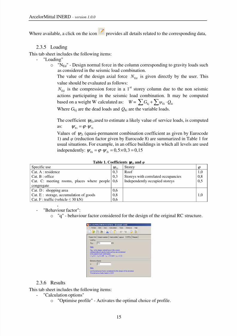
- "Behaviour factor":
o "q" - behaviour factor considered for the design of the original RC structure.
2.3.6 Results
This tab sheet includes the following items:
- "Calculation options"o "Optimise profile" - Activates the optimal choice of profile.

8/7/2019 User and installation manual
http://slidepdf.com/reader/full/user-and-installation-manual 16/18
ArcelorMittal INERD – version 1.0.0
16
"Check series HE": if ticked, the software will take into account the HE
series for steel profile optimisation,
"Check series HD" if ticked, the software will take into account the HD
series for steel profile optimisation,
"Check series UC" if ticked, the software will take into account the UC
series for steel profile optimisation, "Check series IPE" if ticked, the software will take into account the IPE
series for steel profile optimisation,
o "Details" - Provides a table defining whether design conditions and criteria are
fulfilled ( ) or not ( ) for each steel profile of the selected series. These
conditions and criteria are detailed in the Help document "General technical
background of the software". Profiles are sorted according to their cross
sectional area. The optimal profile is the first of the list (i.e. with the smallest
cross section) for which all conditions and criteria are fulfilled.
- "Check data" - Same as the module "Start full data check" defined in 2.1.4.
Note that access to the button "Check data" is not possible when the option "Optimise
profile" is ticked.- "Start calculation" (replaced by "Start optimisation" if the option "Optimise profile" is
ticked) - Launches the module "Start calculation to perform all design checks" defined
in 2.1.5.
- "Show output" - Opens directly the "output" file with all data and results.
- "Selected profile" - Shows the profile taken into account during the computing. Two
arrows allows moving in the steel profiles list sorted by cross section areas.
- "INERD condition checks" - These conditions are detailed in the Help documents
"General technical background of the software" and "Anchorage of the steel profile in
usual conditions". Results of the application of Inerd conditions 1 to 4 are
automatically displayed. A click on "Further results…" displays additional results
related to cross section properties, anchorage checks…
8/7/2019 User and installation manual
http://slidepdf.com/reader/full/user-and-installation-manual 17/18
ArcelorMittal INERD – version 1.0.0
17
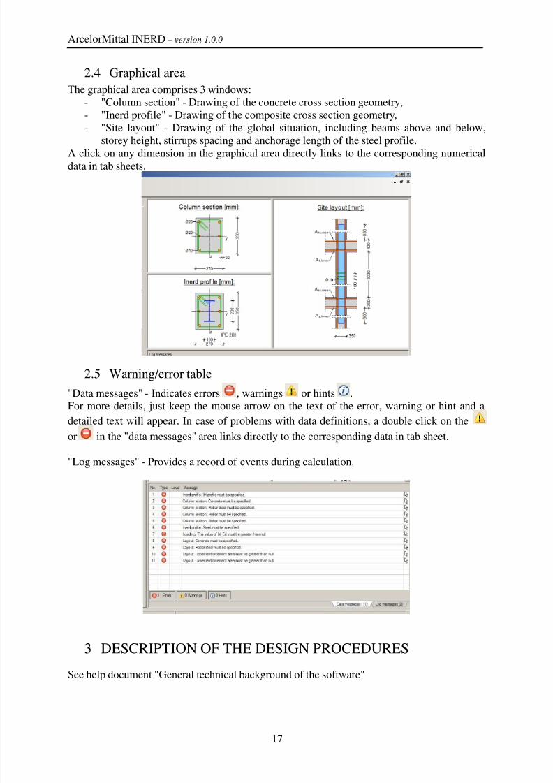
2.4 Graphical area
The graphical area comprises 3 windows:
- "Column section" - Drawing of the concrete cross section geometry,
- "Inerd profile" - Drawing of the composite cross section geometry,
- "Site layout" - Drawing of the global situation, including beams above and below,
storey height, stirrups spacing and anchorage length of the steel profile.A click on any dimension in the graphical area directly links to the corresponding numerical
data in tab sheets.
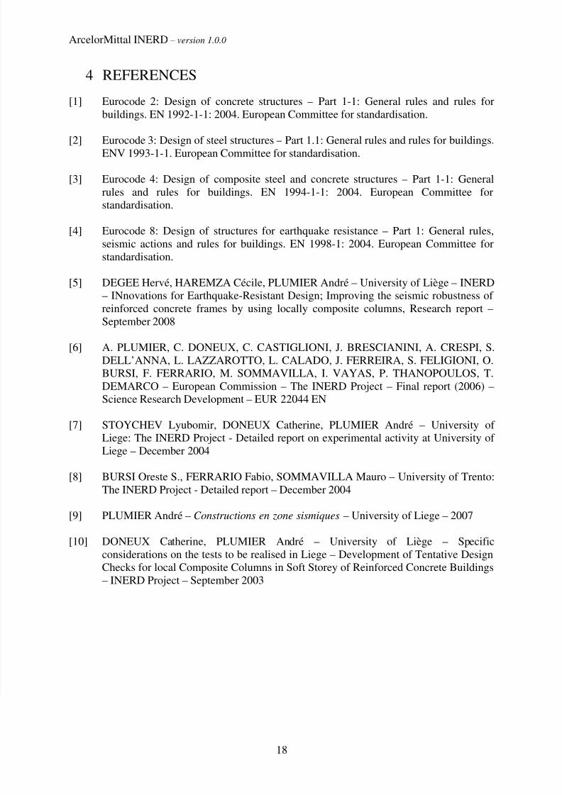
2.5 Warning/error table
"Data messages" - Indicates errors , warnings or hints .
For more details, just keep the mouse arrow on the text of the error, warning or hint and adetailed text will appear. In case of problems with data definitions, a double click on the
or in the "data messages" area links directly to the corresponding data in tab sheet.
"Log messages" - Provides a record of events during calculation.
3 DESCRIPTION OF THE DESIGN PROCEDURES
See help document "General technical background of the software"
8/7/2019 User and installation manual
http://slidepdf.com/reader/full/user-and-installation-manual 18/18
ArcelorMittal INERD – version 1.0.0
18
4 REFERENCES
[1] Eurocode 2: Design of concrete structures – Part 1-1: General rules and rules for
buildings. EN 1992-1-1: 2004. European Committee for standardisation.
[2] Eurocode 3: Design of steel structures – Part 1.1: General rules and rules for buildings.ENV 1993-1-1. European Committee for standardisation.
[3] Eurocode 4: Design of composite steel and concrete structures – Part 1-1: General
rules and rules for buildings. EN 1994-1-1: 2004. European Committee for
standardisation.
[4] Eurocode 8: Design of structures for earthquake resistance – Part 1: General rules,
seismic actions and rules for buildings. EN 1998-1: 2004. European Committee for
standardisation.
[5] DEGEE Hervé, HAREMZA Cécile, PLUMIER André – University of Liège – INERD– INnovations for Earthquake-Resistant Design; Improving the seismic robustness of
reinforced concrete frames by using locally composite columns, Research report –
September 2008
[6] A. PLUMIER, C. DONEUX, C. CASTIGLIONI, J. BRESCIANINI, A. CRESPI, S.
DELL’ANNA, L. LAZZAROTTO, L. CALADO, J. FERREIRA, S. FELIGIONI, O.
BURSI, F. FERRARIO, M. SOMMAVILLA, I. VAYAS, P. THANOPOULOS, T.
DEMARCO – European Commission – The INERD Project – Final report (2006) –
Science Research Development – EUR 22044 EN
[7] STOYCHEV Lyubomir, DONEUX Catherine, PLUMIER André – University of
Liege: The INERD Project - Detailed report on experimental activity at University of
Liege – December 2004
[8] BURSI Oreste S., FERRARIO Fabio, SOMMAVILLA Mauro – University of Trento:
The INERD Project - Detailed report – December 2004
[9] PLUMIER André – Constructions en zone sismiques – University of Liege – 2007
[10] DONEUX Catherine, PLUMIER André – University of Liège – Specific
considerations on the tests to be realised in Liege – Development of Tentative DesignChecks for local Composite Columns in Soft Storey of Reinforced Concrete Buildings
– INERD Project – September 2003