UNIVERSITY OF CALIFORNIA Santa Barbara …ucsb.curby.net/broadcast/thesis/thesis.pdfUNIVERSITY OF...
57
UNIVERSITY OF CALIFORNIA Santa Barbara Cryptanalysis of the SIGABA A Thesis submitted in partial satisfaction of the requirements for the degree Master of Science in Computer Science by Michael Lee Committee in charge: Professor Alan G. Konheim, Chair Professor Richard A. Kemmerer Professor Giovanni Vigna June 2003
Transcript of UNIVERSITY OF CALIFORNIA Santa Barbara …ucsb.curby.net/broadcast/thesis/thesis.pdfUNIVERSITY OF...

UNIVERSITY OF CALIFORNIA
Santa Barbara
Cryptanalysis of the SIGABA
A Thesis submitted in partial satisfaction of the
requirements for the degree Master of Science
in Computer Science
by
Michael Lee
Committee in charge:
Professor Alan G. Konheim, Chair
Professor Richard A. Kemmerer
Professor Giovanni Vigna
June 2003
The Thesis of Michael Lee is approved.
Richard A. Kemmerer
Giovanni Vigna
Alan G. Konheim, Committee Chair
June 2003
Cryptanalysis of the SIGABA
Copyright c© 2003
by
Michael Lee
iii
ABSTRACT
Cryptanalysis of the SIGABA
by
Michael Lee
The SIGABA is a rotor-based cryptosystem developed by the United States
for use during World War II. Its history has been shrouded in secrecy, with the
result that few people know of its significance in securing American communica-
tions during and after World War II. SIGABA’s operational details were finally
declassified in 1996, and the patent for its design was granted in 2001, more than
50 years after it was filed.
In this thesis I present a generic model of rotor-based cryptosystems that
represents a machine at least as difficult to break as the SIGABA. I present tech-
niques that can be used for full plaintext recovery on a cryptosystem using one to
three rotors, and I show how these techniques can be extended to systems using
more rotors. These attacks compromise not only the generic model, but also the
SIGABA and related cryptosystems.
Keywords: rotor machines, cryptanalysis, cribbing, SIGABA, ECM Mark II,CSP-889, M-134-C.
iv

Contents
List of Figures vii
List of Tables viii
1 Introduction 1
2 Rotors 32.1 Rotor Construction . . . . . . . . . . . . . . . . . . . . . . . . . . 32.2 Rotor Encryption . . . . . . . . . . . . . . . . . . . . . . . . . . . 32.3 Using Multiple Rotors . . . . . . . . . . . . . . . . . . . . . . . . 62.4 Interval Rotor Wiring . . . . . . . . . . . . . . . . . . . . . . . . . 7
3 Introducing the SIGABA 93.1 The SIGABA Family . . . . . . . . . . . . . . . . . . . . . . . . . 93.2 SIGABA’s Rotor Banks . . . . . . . . . . . . . . . . . . . . . . . 113.3 Cipher Rotors . . . . . . . . . . . . . . . . . . . . . . . . . . . . . 123.4 Stepping Maze . . . . . . . . . . . . . . . . . . . . . . . . . . . . 13
3.4.1 Control Rotors . . . . . . . . . . . . . . . . . . . . . . . . 133.4.2 Index Rotors . . . . . . . . . . . . . . . . . . . . . . . . . 14
3.5 Operation of the SIGABA . . . . . . . . . . . . . . . . . . . . . . 153.5.1 Setup Procedure . . . . . . . . . . . . . . . . . . . . . . . 163.5.2 Encryption Procedure . . . . . . . . . . . . . . . . . . . . 17
4 Prior Cryptanalysis Efforts 194.1 Attack One: Key Trial . . . . . . . . . . . . . . . . . . . . . . . . 194.2 Attack Two: Superposition . . . . . . . . . . . . . . . . . . . . . . 20
5 Cribbing 24
6 Cryptanalyzing 1-rotor SIGABA 266.1 Attack Model . . . . . . . . . . . . . . . . . . . . . . . . . . . . . 266.2 Attack Three: Substitution Consistency . . . . . . . . . . . . . . 276.3 Strategy . . . . . . . . . . . . . . . . . . . . . . . . . . . . . . . . 286.4 Sample Results . . . . . . . . . . . . . . . . . . . . . . . . . . . . 31
v
6.5 Uniqueness of Rotorstreams . . . . . . . . . . . . . . . . . . . . . 336.6 Extending this Technique . . . . . . . . . . . . . . . . . . . . . . 34
7 Cryptanalyzing 2- and 3-rotor SIGABA 367.1 Attack Model . . . . . . . . . . . . . . . . . . . . . . . . . . . . . 367.2 Attack Four: Plaintext Recovery . . . . . . . . . . . . . . . . . . . 377.3 Cribbing Strategy . . . . . . . . . . . . . . . . . . . . . . . . . . . 377.4 Results of Cribbing . . . . . . . . . . . . . . . . . . . . . . . . . . 397.5 Extending the Crib . . . . . . . . . . . . . . . . . . . . . . . . . . 39
7.5.1 Test 1: Markov Model . . . . . . . . . . . . . . . . . . . . 407.5.2 Test 2: pspell . . . . . . . . . . . . . . . . . . . . . . . . . 447.5.3 Test 3: Customization . . . . . . . . . . . . . . . . . . . . 45
7.6 Performance and Extension . . . . . . . . . . . . . . . . . . . . . 45
8 Conclusion 48
vi
List of Figures
2.1 Generic Rotor . . . . . . . . . . . . . . . . . . . . . . . . . . . . . 42.2 Internal Rotor Wirings . . . . . . . . . . . . . . . . . . . . . . . . 4
3.1 The SIGABA . . . . . . . . . . . . . . . . . . . . . . . . . . . . . 103.2 Rotor Cage and Rotors . . . . . . . . . . . . . . . . . . . . . . . . 123.3 Cipher Rotor Bank . . . . . . . . . . . . . . . . . . . . . . . . . . 133.4 Control Rotor Bank . . . . . . . . . . . . . . . . . . . . . . . . . . 143.5 Index Rotor Bank . . . . . . . . . . . . . . . . . . . . . . . . . . . 15
vii
List of Tables
2.1 Substitution for Sample Rotor . . . . . . . . . . . . . . . . . . . . 52.2 Generation of an Interval Rotor . . . . . . . . . . . . . . . . . . . 8
3.1 Sample key list . . . . . . . . . . . . . . . . . . . . . . . . . . . . 16
4.1 Alphabets for Attack Two . . . . . . . . . . . . . . . . . . . . . . 224.2 Displacements for Attack Two . . . . . . . . . . . . . . . . . . . . 22
6.1 One-Rotor Consistency Test . . . . . . . . . . . . . . . . . . . . . 286.2 One-Rotor Encryption . . . . . . . . . . . . . . . . . . . . . . . . 296.3 Inconsistent Rotorstream . . . . . . . . . . . . . . . . . . . . . . . 296.4 Consistent Rotorstream . . . . . . . . . . . . . . . . . . . . . . . 306.5 Attack Three Algorithm Execution . . . . . . . . . . . . . . . . . 316.6 Results of Algorithm . . . . . . . . . . . . . . . . . . . . . . . . . 326.7 Distinct Consistent Rotorstreams . . . . . . . . . . . . . . . . . . 336.8 Two-Rotor Consistency Test . . . . . . . . . . . . . . . . . . . . . 34
7.1 Multiple Rotor Encryption . . . . . . . . . . . . . . . . . . . . . . 387.2 Multiple Rotor Cribbing . . . . . . . . . . . . . . . . . . . . . . . 407.3 Cribbing with Different Rotor Orders . . . . . . . . . . . . . . . . 407.4 Execution Times for Cribbing . . . . . . . . . . . . . . . . . . . . 46
viii
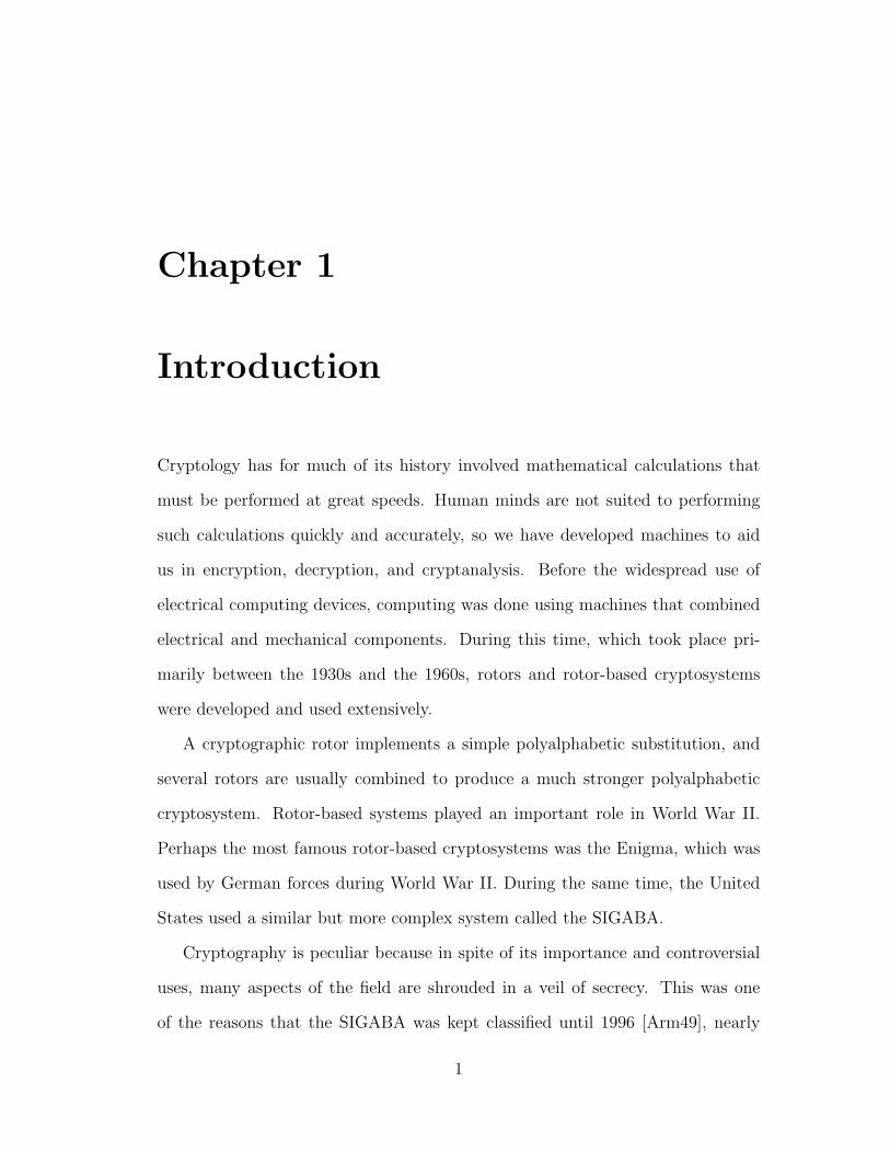
Chapter 1
Introduction
Cryptology has for much of its history involved mathematical calculations that
must be performed at great speeds. Human minds are not suited to performing
such calculations quickly and accurately, so we have developed machines to aid
us in encryption, decryption, and cryptanalysis. Before the widespread use of
electrical computing devices, computing was done using machines that combined
electrical and mechanical components. During this time, which took place pri-
marily between the 1930s and the 1960s, rotors and rotor-based cryptosystems
were developed and used extensively.
A cryptographic rotor implements a simple polyalphabetic substitution, and
several rotors are usually combined to produce a much stronger polyalphabetic
cryptosystem. Rotor-based systems played an important role in World War II.
Perhaps the most famous rotor-based cryptosystems was the Enigma, which was
used by German forces during World War II. During the same time, the United
States used a similar but more complex system called the SIGABA.
Cryptography is peculiar because in spite of its importance and controversial
uses, many aspects of the field are shrouded in a veil of secrecy. This was one
of the reasons that the SIGABA was kept classified until 1996 [Arm49], nearly
1
four decades after it was retired. After the details of the SIGABA’s design and
operation were declassified, the cryptographic community gradually learned of its
significance. One historian notes: “It was one of the top ten most important
technologies of WW II . . . but virtually nothing has been written about it because
it remained classified for all those years” [Pek01]. While both sides of the war had
success in breaking certain enemy cryptosystems, the SIGABA was one of the few
systems believed to have avoided compromise throughout its period of service. In
fact, German cryptanalysts even stopped intercepting SIGABA messages because
they believed it to be impregnable. Even modern cryptanalysis of the machine
was made difficult due to the complexity of the design.
This thesis will present further progress on the cryptanalysis of the SIGABA.
In Chapter 2, I introduce rotors and rotor-based machines in general. Chapter 3
describes the design and operation of the SIGABA. Chapter 4 summarizes existing
cryptanalytic work, and Chapters 5 through 7 describe the new cryptanalytic
techniques used to break models of the SIGABA. I conclude in Chapter 8.
2
Chapter 2
Rotors
Rotor-based cryptosystems are so called because of their use of electro-mechanical
components called rotors.
2.1 Rotor Construction
A cryptographic rotor is a disk with electrical contacts arranged in a circle on
both sides, and a series of teeth set into the circumference of the disk (see Figure
2.1). A geared mechanism in the machine meshes with the rotor’s teeth and causes
it to turn around a central axis. Thus, a rotor interacts with the cryptosystem
via both an electrical interface that is used to encrypt letters and a mechanical
interface that is used to turn the rotor. (Cipher disks are similar to rotors but
are purely mechanical, and therefore have no electrical contacts [CSE].)
2.2 Rotor Encryption
Wires within the disc connect contacts on one side to those on the other side in a
one-to-one mapping. Therefore, a rotor implements a monoalphabetic substitution.
3
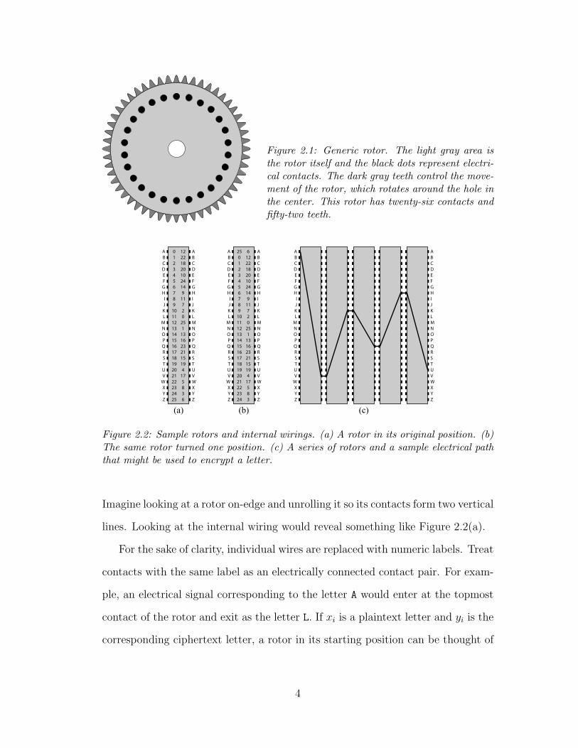
Figure 2.1: Generic rotor. The light gray area isthe rotor itself and the black dots represent electri-cal contacts. The dark gray teeth control the move-ment of the rotor, which rotates around the hole inthe center. This rotor has twenty-six contacts andfifty-two teeth.
A B C D E F G H I J K L
M N O P Q R S T U V
W X Y Z
A B C D E F G H I J K L M N O P Q R S T U V W X Y Z
0 1 2 3 4 5 6 7 8 9
10 11 12 13 14 15 16 17 18 19 20 21 22 23 24 25
12 22 18 20 10 24 14 9
11 7 2 0
25 1
13 16 23 21 15 19 4
17 5 8 3 6
A B C D E F G H I J K L
M N O P Q R S T U V
W X Y Z
A B C D E F G H I J K L
M N O P Q R S T U V
W X Y Z
A B C D E F G H I J K L M N O P Q R S T U V W X Y Z
A B C D E F G H I J K L M N O P Q R S T U V W X Y Z
25 0 1 2 3 4 5 6 7 8 9
10 11 12 13 14 15 16 17 18 19 20 21 22 23 24
6 12 22 18 20 10 24 14 9
11 7 2 0
25 1
13 16 23 21 15 19 4
17 5 8 3
(a) (b) (c)
Figure 2.2: Sample rotors and internal wirings. (a) A rotor in its original position. (b)The same rotor turned one position. (c) A series of rotors and a sample electrical paththat might be used to encrypt a letter.
Imagine looking at a rotor on-edge and unrolling it so its contacts form two vertical
lines. Looking at the internal wiring would reveal something like Figure 2.2(a).
For the sake of clarity, individual wires are replaced with numeric labels. Treat
contacts with the same label as an electrically connected contact pair. For exam-
ple, an electrical signal corresponding to the letter A would enter at the topmost
contact of the rotor and exit as the letter L. If xi is a plaintext letter and yi is the
corresponding ciphertext letter, a rotor in its starting position can be thought of
4
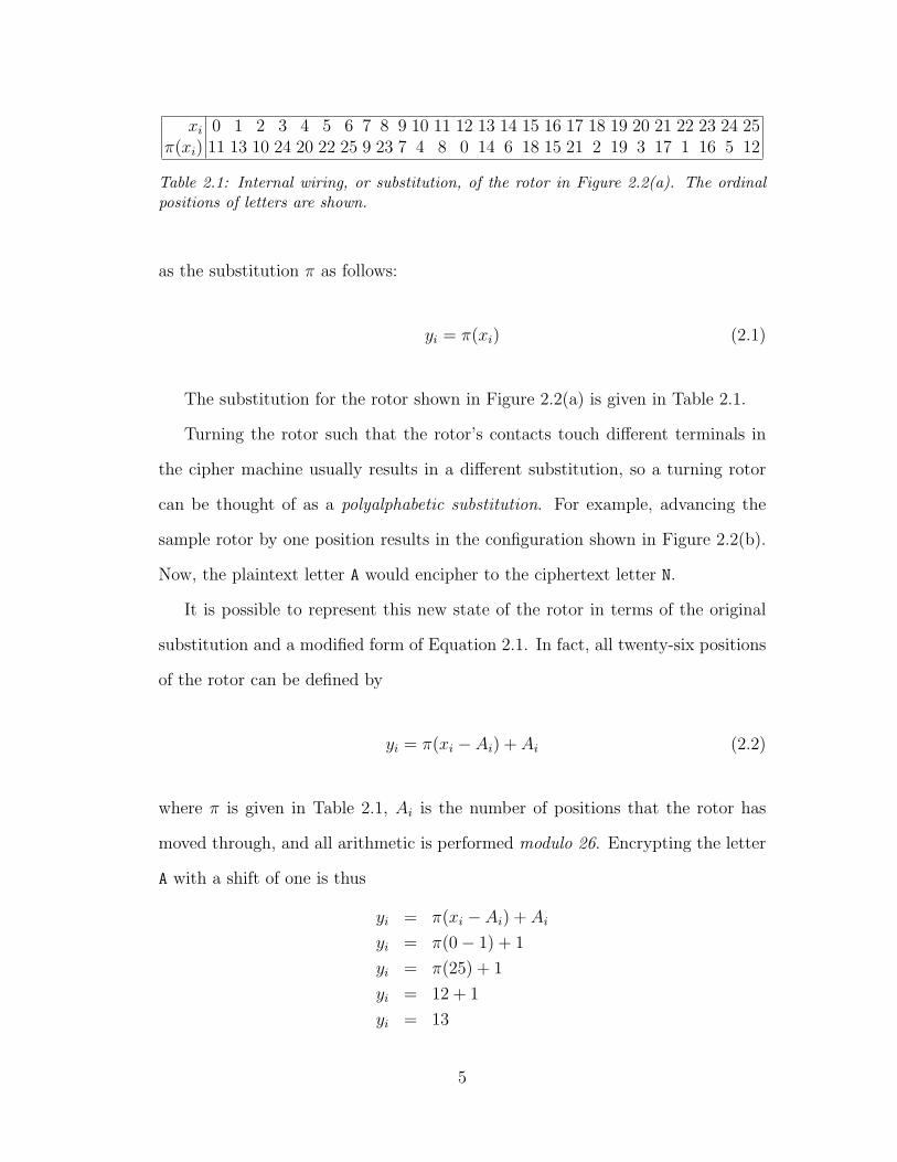
xi 0 1 2 3 4 5 6 7 8 9 10 11 12 13 14 15 16 17 18 19 20 21 22 23 24 25π(xi) 11 13 10 24 20 22 25 9 23 7 4 8 0 14 6 18 15 21 2 19 3 17 1 16 5 12
Table 2.1: Internal wiring, or substitution, of the rotor in Figure 2.2(a). The ordinalpositions of letters are shown.
as the substitution π as follows:
yi = π(xi) (2.1)
The substitution for the rotor shown in Figure 2.2(a) is given in Table 2.1.
Turning the rotor such that the rotor’s contacts touch different terminals in
the cipher machine usually results in a different substitution, so a turning rotor
can be thought of as a polyalphabetic substitution. For example, advancing the
sample rotor by one position results in the configuration shown in Figure 2.2(b).
Now, the plaintext letter A would encipher to the ciphertext letter N.
It is possible to represent this new state of the rotor in terms of the original
substitution and a modified form of Equation 2.1. In fact, all twenty-six positions
of the rotor can be defined by
yi = π(xi − Ai) + Ai (2.2)
where π is given in Table 2.1, Ai is the number of positions that the rotor has
moved through, and all arithmetic is performed modulo 26. Encrypting the letter
A with a shift of one is thus
yi = π(xi − Ai) + Ai
yi = π(0− 1) + 1
yi = π(25) + 1
yi = 12 + 1
yi = 13
5
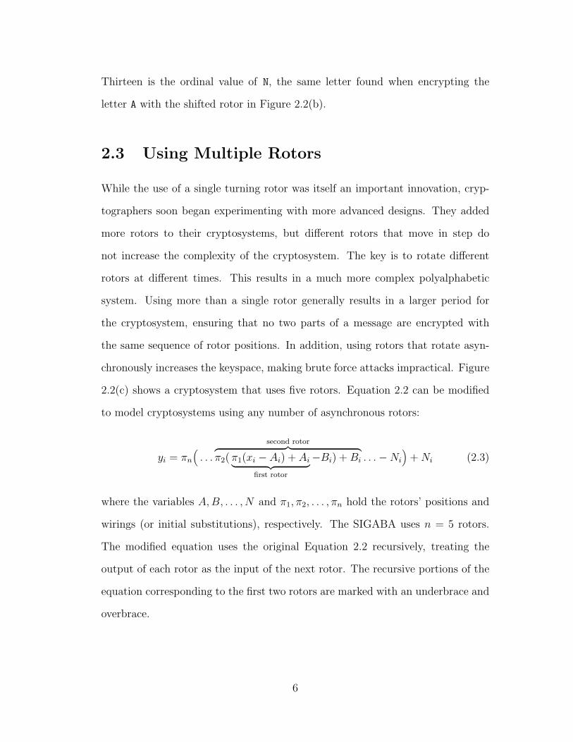
Thirteen is the ordinal value of N, the same letter found when encrypting the
letter A with the shifted rotor in Figure 2.2(b).
2.3 Using Multiple Rotors
While the use of a single turning rotor was itself an important innovation, cryp-
tographers soon began experimenting with more advanced designs. They added
more rotors to their cryptosystems, but different rotors that move in step do
not increase the complexity of the cryptosystem. The key is to rotate different
rotors at different times. This results in a much more complex polyalphabetic
system. Using more than a single rotor generally results in a larger period for
the cryptosystem, ensuring that no two parts of a message are encrypted with
the same sequence of rotor positions. In addition, using rotors that rotate asyn-
chronously increases the keyspace, making brute force attacks impractical. Figure
2.2(c) shows a cryptosystem that uses five rotors. Equation 2.2 can be modified
to model cryptosystems using any number of asynchronous rotors:
yi = πn
(. . .
second rotor︷ ︸︸ ︷π2( π1(xi − Ai) + Ai︸ ︷︷ ︸
first rotor
−Bi) + Bi . . .−Ni
)+ Ni (2.3)
where the variables A, B, . . . , N and π1, π2, . . . , πn hold the rotors’ positions and
wirings (or initial substitutions), respectively. The SIGABA uses n = 5 rotors.
The modified equation uses the original Equation 2.2 recursively, treating the
output of each rotor as the input of the next rotor. The recursive portions of the
equation corresponding to the first two rotors are marked with an underbrace and
overbrace.
6
2.4 Interval Rotor Wiring
A rotor should always be wired so that as it advances through each of its positions,
it forms substitutions that are as different as possible. The displacement of a rotor
wire i, called D(i), is the distance between its contacts:
D(i) = π(i)− i 0 ≤ i < n (2.4)
where n is the number of contacts on each side of the rotor. Consider a rotor that
connects contacts on one side directly to those on the other side. Such a straight-
through rotor would produce the same substitution regardless of its position. This
is because every wire displaces the input by the same number. As such a rotor
advances, each contact is still displaced by the same amount, and the substitution
does not change.
On the other hand, consider another rotor where every contact will connect
to many different contacts on the other side as the rotor moves, resulting in a
more complex polyalphabetic substitution. For example, as the rotor in Figure
2.2(a) turns, the letter A will encrypt to the letters L, N, H, T, and so on. The
ultimate goal would be to create an interval rotor, a rotor whose displacements
are a permutation of the numbers 0, 1, 2, . . . , n− 1. Unfortunately, interval rotors
that never repeat a displacement are only possible when there are an odd number
of contacts on each side. For rotors with an even number of contact pairs, such
as those often used for encryption of English text, at least one displacement must
be used twice and at least once displacement will not be used. For example, the
rotor shown in Figure 2.2(a) uses the displacement 19 twice and it doesn’t use the
displacement 6 at all.
Generating an interval rotor is an example of a constraint satisfaction problem.
7

i 0 1 2 3 4 5 6 7 8 9 10 11 12 13 14 15 16 17 18 19 20 21 22 23 24 25D(i) 7 3 4 14 22 12 2 11 20 17 23 9 24 10 0 15 25 1 8 5 13 6 21 19 18 16
π H E G R A R I S C A H U K X O E P S A Y H B R Q Q P...
......
D(i) 14 19 21 3 7 23 4 8 16 22 11 2 17 20 24 15 10 1 25 0 5 6 13 12 18 9π O U X G L C K P Y F V N D H M E A S R T Z B J J Q I
D(i) 14 19 21 3 7 23 4 8 16 22 11 2 17 20 24 15 10 1 25 0 5 6 0 12 18 9π O U X G L C K P Y F V N D H M E A S R T Z B W J Q I
Table 2.2: Using the Interval Method. Collisions are shown in boldface. When only onecollision remains, one wire is remapped to eliminate it. The final rotor wiring withoutany collisions is given on the bottom line.
Another such problem is the N -queens problem, which tries to put N queens on
an N ×N chess board such that no two queens share a diagonal, row, or column.
In this case, we must use 26 wires of varying lengths to connect contacts of a rotor.
The algorithm used is adapted from the N -queens algorithm proposed in [SG90].
A rotor is generated with a pseudo-random wiring, and collisions between wires
mapping to the same contact are gradually taken away. When only one collision
remains, it is solved by remapping one of the conflicting wires. This process is
shown in Table 2.2. In this example, the last remaining collision is between two
J letters, and the letter W is not used. When the first J is mapped to W instead,
the displacement 0 gets used twice, but the displacement 13 isn’t used at all.
8
Chapter 3
Introducing the SIGABA
Development of the SIGABA (Figure 3.1) occurred primarily during the 1930s
under Frank Rowlett and William Friedman in the U.S. Army, and Joseph Wenger
and Laurence Safford, among others, in the U.S. Navy [Pek02]. The original
machine was used only by the United States, but it was later modified to allow it to
communicate with the British Typex machine [CSE]. This section will summarize
the design and operation of the SIGABA, concentrating on its encryption mode
since the rotors move the same way for decryption.
3.1 The SIGABA Family
ECM Mark I: An early rotor-based cryptosystem designed by Edward Hebern
during World War I. ECM stands for Electronic Code Machine, or alter-
nately, Electric Cipher Machine.
M-134-C: A U.S. Army designation for the SIGABA. The other models of the
M-134 series were predecessors of the final SIGABA, and featured different
ways of randomizing rotor movements. Most notably, the M-134-A included
9
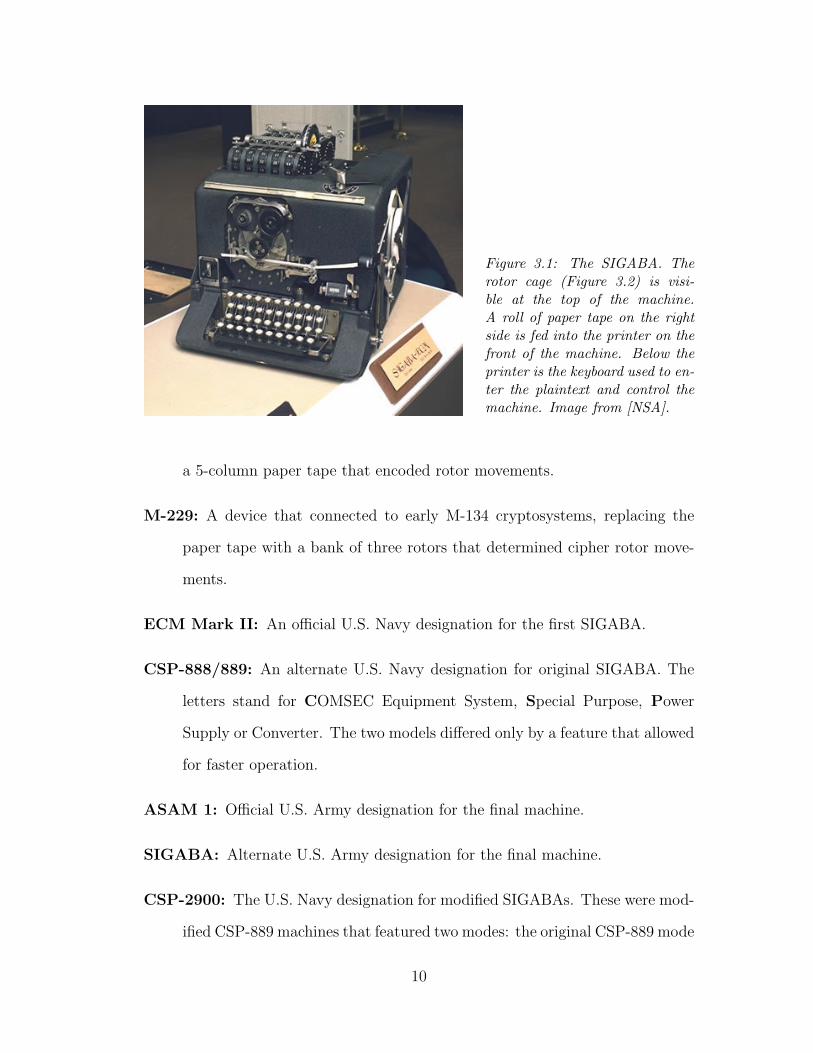
Figure 3.1: The SIGABA. Therotor cage (Figure 3.2) is visi-ble at the top of the machine.A roll of paper tape on the rightside is fed into the printer on thefront of the machine. Below theprinter is the keyboard used to en-ter the plaintext and control themachine. Image from [NSA].
a 5-column paper tape that encoded rotor movements.
M-229: A device that connected to early M-134 cryptosystems, replacing the
paper tape with a bank of three rotors that determined cipher rotor move-
ments.
ECM Mark II: An official U.S. Navy designation for the first SIGABA.
CSP-888/889: An alternate U.S. Navy designation for original SIGABA. The
letters stand for COMSEC Equipment System, Special Purpose, Power
Supply or Converter. The two models differed only by a feature that allowed
for faster operation.
ASAM 1: Official U.S. Army designation for the final machine.
SIGABA: Alternate U.S. Army designation for the final machine.
CSP-2900: The U.S. Navy designation for modified SIGABAs. These were mod-
ified CSP-889 machines that featured two modes: the original CSP-889 mode
10
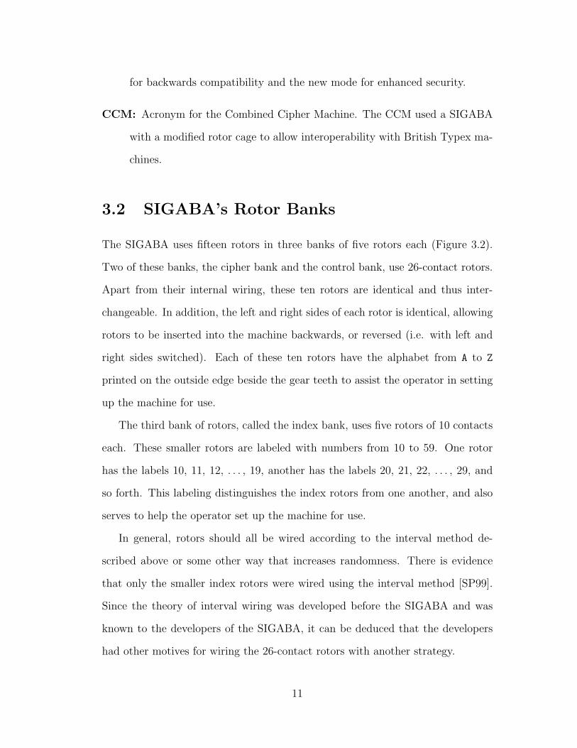
for backwards compatibility and the new mode for enhanced security.
CCM: Acronym for the Combined Cipher Machine. The CCM used a SIGABA
with a modified rotor cage to allow interoperability with British Typex ma-
chines.
3.2 SIGABA’s Rotor Banks
The SIGABA uses fifteen rotors in three banks of five rotors each (Figure 3.2).
Two of these banks, the cipher bank and the control bank, use 26-contact rotors.
Apart from their internal wiring, these ten rotors are identical and thus inter-
changeable. In addition, the left and right sides of each rotor is identical, allowing
rotors to be inserted into the machine backwards, or reversed (i.e. with left and
right sides switched). Each of these ten rotors have the alphabet from A to Z
printed on the outside edge beside the gear teeth to assist the operator in setting
up the machine for use.
The third bank of rotors, called the index bank, uses five rotors of 10 contacts
each. These smaller rotors are labeled with numbers from 10 to 59. One rotor
has the labels 10, 11, 12, . . . , 19, another has the labels 20, 21, 22, . . . , 29, and
so forth. This labeling distinguishes the index rotors from one another, and also
serves to help the operator set up the machine for use.
In general, rotors should all be wired according to the interval method de-
scribed above or some other way that increases randomness. There is evidence
that only the smaller index rotors were wired using the interval method [SP99].
Since the theory of interval wiring was developed before the SIGABA and was
known to the developers of the SIGABA, it can be deduced that the developers
had other motives for wiring the 26-contact rotors with another strategy.
11
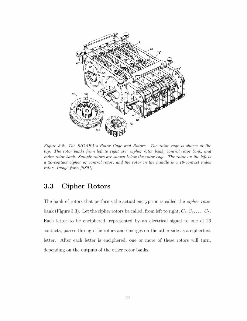
Figure 3.2: The SIGABA’s Rotor Cage and Rotors. The rotor cage is shown at thetop. The rotor banks from left to right are: cipher rotor bank, control rotor bank, andindex rotor bank. Sample rotors are shown below the rotor cage. The rotor on the left isa 26-contact cipher or control rotor, and the rotor in the middle is a 10-contact indexrotor. Image from [SS01].
3.3 Cipher Rotors
The bank of rotors that performs the actual encryption is called the cipher rotor
bank (Figure 3.3). Let the cipher rotors be called, from left to right, C1, C2, . . . , C5.
Each letter to be enciphered, represented by an electrical signal to one of 26
contacts, passes through the rotors and emerges on the other side as a ciphertext
letter. After each letter is enciphered, one or more of these rotors will turn,
depending on the outputs of the other rotor banks.
12

Signals FromIndex Rotors
PlaintextLetters from
Keyboard
CiphertextLetters toPrinter
C 1 C 2 C 3 C 4 C 5
Figure 3.3: Cipher RotorBank. Each of the blackboxes under the rotors rep-resents an actuator thatmoves the appropriate ro-tor when given a signalfrom the index rotors.
3.4 Stepping Maze
While other rotor-based cryptosystems tended to rotate their rotors as an odome-
ter (with the last rotor moving one position per letter, and each other rotor moving
one position when the rotor after it completes a full cycle), the SIGABA intro-
duces an innovative concept. The movement of its cipher rotors depend on the
two other rotor banks, collectively known as the stepping maze. The output of
the stepping maze is not seen directly, but rather controls the movements of the
cipher rotors. Thus, the SIGABA uses a hidden cryptosystem within another
cryptosystem.
3.4.1 Control Rotors
To determine which rotors will turn after a letter is enciphered, electrical signals
are applied to four inputs of the control rotor bank (Figure 3.4), which is the first
part of the stepping maze. Let the control rotors be named, from left to right,
R1, R2, . . . , R5. When the machine is set up for encryption, all control rotors
13
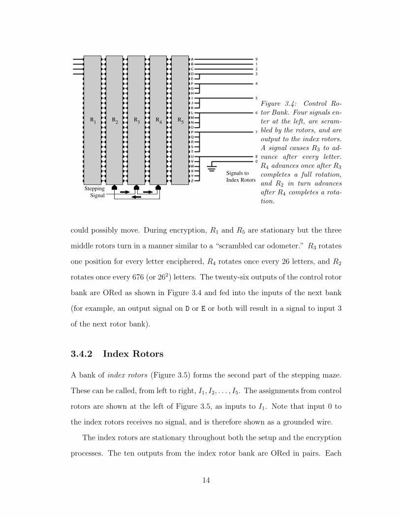
SteppingSignal
Signals toIndex Rotors
9 1 2 3 4 5 6 7 8�0
A B C D E F G H I J K L M N O P Q R S T U V W X Y Z
R 1 R 2 R 3 R 4 R 5
Figure 3.4: Control Ro-tor Bank. Four signals en-ter at the left, are scram-bled by the rotors, and areoutput to the index rotors.A signal causes R3 to ad-vance after every letter.R4 advances once after R3
completes a full rotation,and R2 in turn advancesafter R4 completes a rota-tion.
could possibly move. During encryption, R1 and R5 are stationary but the three
middle rotors turn in a manner similar to a “scrambled car odometer.” R3 rotates
one position for every letter enciphered, R4 rotates once every 26 letters, and R2
rotates once every 676 (or 262) letters. The twenty-six outputs of the control rotor
bank are ORed as shown in Figure 3.4 and fed into the inputs of the next bank
(for example, an output signal on D or E or both will result in a signal to input 3
of the next rotor bank).
3.4.2 Index Rotors
A bank of index rotors (Figure 3.5) forms the second part of the stepping maze.
These can be called, from left to right, I1, I2, . . . , I5. The assignments from control
rotors are shown at the left of Figure 3.5, as inputs to I1. Note that input 0 to
the index rotors receives no signal, and is therefore shown as a grounded wire.
The index rotors are stationary throughout both the setup and the encryption
processes. The ten outputs from the index rotor bank are ORed in pairs. Each
14

Signals FromControl Rotors
Signals toCipher RotorActuators
1 2 3 4 5 6 7 8 9 0
C
C
C
C
C
5
4
3
2
1
B C
D, E F, G, H
I, J, K L, M, N, O
P, Q, R, S, T U, V, W, X, Y, Z
A
I1 I2 I3 I4 I5
Figure 3.5: Index RotorBank. Signals enter onthe left, are further scram-bled by the index rotors,and exit at the right tosignal cipher rotor move-ments.
pair of wires controls one cipher rotor; an electrical signal on either wire causes
the associated cipher rotor to turn after a letter is encrypted.
Since there are initially four active inputs to the control rotors and signals
never split in two, at most four rotors can turn after any letter is encrypted.
While signals are combined together between banks of rotors, they are never
completely lost, so there is always at least one rotor that will turn after every
letter. On the surface, this might seem bad because randomly moving rotors
might all advance or all stay still after any given letter is encrypted. However,
the substitution is monoalphabetic if no rotors turn, and weak if all rotors turn
at once. Therefore, it seems that the designers valued a continuously changing
substitution over increased randomness in rotor movements.
3.5 Operation of the SIGABA
The operation of the SIGABA can be described in two parts: preparing the ma-
chine for encryption, and actually performing the encryption. (Again, since the
operation of the machine for encryption and decryption are nearly identical, the
description here will consider only encryption. In general, the same steps are
performed for decryption.)
15

Day Rotor Arrangement SECRETof Control Cipher Index CheckMonth Rotors Rotors Rotors Group1 0R 4 6 2R 7 1 8 5 9 3R 10 23 31 49 55 R N H V C
2 2 3R 9R 1 5 6 4R 8 7 0 14 25 33 46 59 S E M N O...
......
......
Day CONFIDENTIAL RESTRICTEDof Index Check Index CheckMonth Rotors Group Rotors Group1 12 28 31 44 53 P W V M T 17 25 36 43 58 M C S D T
2 15 20 32 48 56 E H E W B 10 27 34 42 56 R S T H H...
......
......
Table 3.1: Sample key list from [Arm49]. Each day of the month has a rotor arrangementgiving the order that 26-contact rotors should be placed into the control and cipher rotorbanks. The letter R indicates that the rotor should be inserted backwards. In addition,index rotor positions and check groups are provided for each of three different securityclassifications.
3.5.1 Setup Procedure
The instructions for preparing the SIGABA for encryption are broken down into
five steps. This information has been condensed from the Army’s SIGABA manual
[Arm49]. Refer to the manual for full details about SIGABA operation.
First, control and cipher rotors are placed into their rotor banks in the order
and orientation (normal or reversed) given in an official key list. The key list has
a different rotor order and orientation for the control and cipher rotors for every
day of the month, as shown in Table 3.1. During this step, the position of each
rotor from A to Z does not matter, since they will be aligned later. Alignment
marks on the rotor cage ensure that rotors are properly seated.
Secondly, index rotors are inserted into the index rotor bank in accordance with
the official key list. The keylist has three index rotor placements (corresponding
to different security classifications) for every day of the month, as shown in Table
3.1. Since each index rotor has unique labeling, there is only one way index rotors
16
can be inserted correctly. Again, there are marks on the rotor cage to help align
the index rotors.
After the rotors are all placed, a “26–30 check group” is produced to make sure
the rotors are in the correct locations and orientations. A Zeroize function on the
machine is used to turn all the cipher and control rotors to the letter O. Then the
letter A is encrypted thirty times, and the last five outputs are compared with the
corresponding group listed in the official key list. If every character matches, then
there is little chance that an error has occurred. Dirty contacts and misplaced
rotors are common causes of errors.
The operator will then choose a random group of five letters that will identify
the message. This message indicator cannot be any “bona fide five-letter word,”
even though such words do occur at random. A different message indicator must
be used for every message, or part of a message.
Lastly, the rotors are aligned with respect to the message indicator. First,
the machine is once again Zeroized, then control rotors are advanced one at a
time until their labels match the letters of the message indicator. During this
time, both control and cipher rotors can be expected to turn. After this step, the
machine is ready to encrypt plaintext.
3.5.2 Encryption Procedure
Once the SIGABA is prepared for use as described above, the process of encryp-
tion is relatively simple. The operator types out an unencrypted standard header
including the message indicator. Note that in order for the receiver to decrypt the
message, he or she must have the unencrypted message indicator. Then the plain-
text is typed in and encrypted. After every letter, the rotors move as described
in the previous section. When the encryption is complete, an unencrypted footer
17

is appended to the message. Lastly the total output, which has been printed on
a paper tape, can be taken from the machine.
18
Chapter 4
Prior Cryptanalysis Efforts
John Savard and Richard Pekelney attempted a cryptanalysis of the SIGABA in
their 1999 paper “The ECM Mark II: Design, History and Cryptology” [SP99].
Their paper provides comprehensive details pertaining to the design and operation
of the SIGABA, and also attempts to break the cipher. Specifically, the authors
develop two techniques.
4.1 Attack One: Key Trial
The first attack can be summarized as follows:
Given:• Ciphertext• Internal wirings of all fifteen rotors
Find:• The order of the rotors• The cipher rotors’ positions and movements
They determine that the keyspace of the rotor orders and rotor settings com-
bined represent the equivalent of a 48.6-bit key, which would be susceptible to a
19
brute-force search on modern hardware. The attack would consist of exhaustively
attempting decryptions with all possible keys until the correct one is found.
Actually, the keyspace is over 70 bits. First, there are 10! ways of arranging
the ten 26-contact rotors within the machine. For each of those arrangements, the
rotors can be inserted in reverse, leading to 210 more variations per arrangement.
For each of those possibilities, there are 265 ways of setting the control and cipher
rotors’ positions, since that depends on the five-letter message indicator. From
the manual, it appears as if index rotors always appear in order from smallest
label to largest label. Even so, the index rotors may be turned to any one of
105 configurations depending on the date and the security classification of the
message. Thus, the effective key length is approximately
log2(10!× 210 × 265 × 105) = 71.9
bits. Regardless of the effective key size, this method of cryptanalysis is not
efficient.
4.2 Attack Two: Superposition
The second attack is summarized below:
Given:• 10–15 ciphertexts using the same key• Corresponding plaintexts
Find:• Internal wirings of the cipher rotors• The cipher rotors’ positions and movements
This second attack uses different ciphertexts resulting from identical keys to
reproduce consecutive enciphering alphabets. Unfortunately, it is difficult to find
20
so many messages enciphered with the same key. Since every day has different
rotor settings, as specified in the official key list, all such messages must be gener-
ated on the same day. In addition, each message depends on a message indicator,
as described in the previous chapter. It is unlikely that an operator will be so
careless as to use the same message indicator ten or more times on the same day,
though perhaps message intercepts from different stations could yield the required
volume.
Assuming that 10 or more messages encrypted with the same key can be found,
the attack allows for the cryptanalyst to recover not only the cipher rotors’ move-
ments, but also their internal wiring schemes. The attack uses the ciphertexts to
reconstruct substitutions of the rotors. It does this by identifying different times
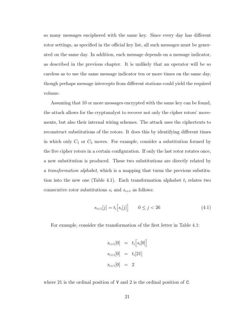
in which only C1 or C5 moves. For example, consider a substitution formed by
the five cipher rotors in a certain configuration. If only the last rotor rotates once,
a new substitution is produced. These two substitutions are directly related by
a transformation alphabet, which is a mapping that turns the previous substitu-
tion into the new one (Table 4.1). Each transformation alphabet ti relates two
consecutive rotor substitutions si and si+1 as follows:
si+1[j] = ti[si[j]
]0 ≤ j < 26 (4.1)
For example, consider the transformation of the first letter in Table 4.1:
si+1[0] = ti[si[0]
]si+1[0] = ti[21]
si+1[0] = 2
where 21 is the ordinal position of V and 2 is the ordinal position of C.
21
si V T U W N B J H E M Q S D F R I A Y O X G K L Z P Cti A G N T U M J L Q W F R B E V O H P X S Y C I Z D K
si+1 C S Y I E G W L U B H X T M P Q A D V Z J F R K O N...
......
sj I M C V T O Z K H N S G B Y D Q F A U P W E L X R Jtj C G N D J Q W X P M O T Z I U E H Y R K S A V B F L
sj+1 P Z N A K U L O X I R W G F D H Q C S E V J T B Y M
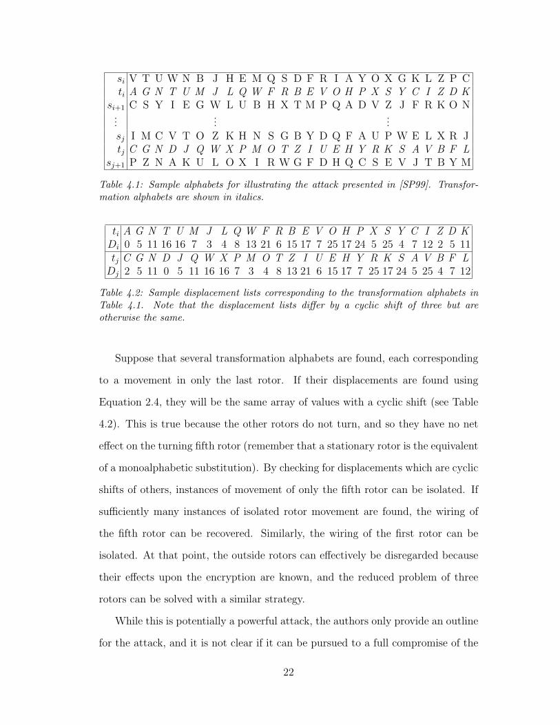
Table 4.1: Sample alphabets for illustrating the attack presented in [SP99]. Transfor-mation alphabets are shown in italics.
ti A G N T U M J L Q W F R B E V O H P X S Y C I Z D KDi 0 5 11 16 16 7 3 4 8 13 21 6 15 17 7 25 17 24 5 25 4 7 12 2 5 11tj C G N D J Q W X P M O T Z I U E H Y R K S A V B F L
Dj 2 5 11 0 5 11 16 16 7 3 4 8 13 21 6 15 17 7 25 17 24 5 25 4 7 12
Table 4.2: Sample displacement lists corresponding to the transformation alphabets inTable 4.1. Note that the displacement lists differ by a cyclic shift of three but areotherwise the same.
Suppose that several transformation alphabets are found, each corresponding
to a movement in only the last rotor. If their displacements are found using
Equation 2.4, they will be the same array of values with a cyclic shift (see Table
4.2). This is true because the other rotors do not turn, and so they have no net
effect on the turning fifth rotor (remember that a stationary rotor is the equivalent
of a monoalphabetic substitution). By checking for displacements which are cyclic
shifts of others, instances of movement of only the fifth rotor can be isolated. If
sufficiently many instances of isolated rotor movement are found, the wiring of
the fifth rotor can be recovered. Similarly, the wiring of the first rotor can be
isolated. At that point, the outside rotors can effectively be disregarded because
their effects upon the encryption are known, and the reduced problem of three
rotors can be solved with a similar strategy.
While this is potentially a powerful attack, the authors only provide an outline
for the attack, and it is not clear if it can be pursued to a full compromise of the
22
SIGABA. For example, the authors acknowledge the possibility of false positives,
where movements of rotors other than the fifth rotor might be incorrectly seen
as movement by the fifth rotor only. In addition, it is unlikely that the neces-
sary ciphertexts could ever be recovered in actual use, since so many ciphertexts
with the same key are required. Nonetheless, their efforts pave the way for new
developments.
23
Chapter 5
Cribbing
The cryptanalysis described below relies on a technique known as cribbing. In
the context of cryptanalysis, a crib is any word or phrase that the cryptanalyst
expects to be in the plaintext. With this knowledge, the analyst can then look
for representations of the crib in the ciphertext, and hope to gather more infor-
mation once the corresponding ciphertext is found. This is similar to the idea
of adaptive-chosen-plaintext cryptanalysis [Sch96], in which the attacker repeat-
edly encrypts plaintexts with varying parameters that depend on the results of
previous encryption attempts.
Guessing good cribs is generally not difficult because attackers do not usually
attack random ciphertexts. They have some motive to break a cryptosystem
or ciphertext, and that reason might provide clues about the subject or general
content of a message. For example, an adversary during war might talk about
troop movements, supply lines, and attack plans. A target of corporate espionage
might talk about product designs, profit margins, or marketing campaigns. These
and others are suitable cribs to try. Even when nothing is known about the
message, common phrases in the target language, such as “there are” in English,
could be searched for. In addition, as messages are successfully decrypted, the
24

attacker learns more and more about the communications of the target and is
more easily able to guess good cribs.
25
Chapter 6
Cryptanalyzing 1-rotor SIGABA
In this initial step, we attack a cryptosystem that uses one cipher rotor.
6.1 Attack Model
The machine that will be attacked resembles a modified SIGABA. First of all,
there is only one cipher rotor. Secondly, the stepping maze will be ignored for the
duration of this attack. Since the stepping maze is itself a hidden cryptosystem,
it would be difficult to recover its details. Thankfully, the stepping maze is not
required for simulating the machine. The movement of each rotor can be repre-
sented by a rotorstream: a bitstream, denoted a, where a 1 represents movement
after enciphering a letter and a 0 represents no movement after enciphering. The
rotorstream can be thought of as the following:
a = (a0, a1, . . . , an−2) ai ∈ {0, 1} (0 ≤ i < n− 1)
Only n− 1 rotorstream bits are required for encrypting n characters because
each bit represents movement that occurs between enciphering two letters. When
26
a is recovered, its bits will perform the same role as the stepping maze outputs
and tell the cipher rotor when to advance. Using a and the initial rotor position
A0, the complete sequence of rotor positions, denoted A, can be defined as:
A = (A0, A1, . . . , An−1)
Ai =
A0 if i = 0
Ai−1 + ai−1 if 1 ≤ i < n
6.2 Attack Three: Substitution Consistency
The cryptanalysis can be summarized as follows:
Given:• Ciphertext• A crib within the corresponding plaintext
Find:• The internal wiring of the cipher rotor• The rotor’s position when the crib is found• The cipher rotor’s rotorstream
Depending on the length of the crib and the characteristics of the plaintext,
it is possible that the complete internal wiring might not be found, or that more
than one rotorstream may be found that fits the ciphertext and plaintext. How-
ever, as cribs of increasing length are used, incorrect rotorstreams are generally
eliminated, leaving the rotorstream that will recover part of the original cipher
rotor’s wiring. For the rest of this section, let the word substitution refer to a
single letter mapping, for example D→L, and let the word wiring refer to all of the
substitutions in a rotor collectively.
27
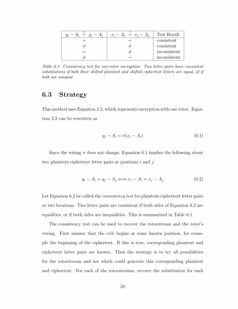
yi − Ai?= yj − Aj xi − Ai
?= xj − Aj Test Result
= = consistent6= 6= consistent= 6= inconsistent6= = inconsistent
Table 6.1: Consistency test for one-rotor encryption. Two letter pairs have consistentsubstitutions if both their shifted plaintext and shifted ciphertext letters are equal, of ifboth are unequal.
6.3 Strategy
This method uses Equation 2.2, which represents encryption with one rotor. Equa-
tion 2.2 can be rewritten as
yi − Ai = π(xi − Ai) (6.1)
Since the wiring π does not change, Equation 6.1 implies the following about
two plaintext-ciphertext letter pairs at positions i and j:
yi − Ai = yj − Aj ⇐⇒ xi − Ai = xj − Aj (6.2)
Let Equation 6.2 be called the consistency test for plaintext-ciphertext letter pairs
at two locations. Two letter pairs are consistent if both sides of Equation 6.2 are
equalities, or if both sides are inequalities. This is summarized in Table 6.1.
The consistency test can be used to recover the rotorstream and the rotor’s
wiring. First assume that the crib begins at some known position, for exam-
ple the beginning of the ciphertext. If this is true, corresponding plaintext and
ciphertext letter pairs are known. Then the strategy is to try all possibilities
for the rotorstream and see which could generate this corresponding plaintext
and ciphertext. For each of the rotorstreams, recover the substitution for each
28

xi C O M P U T E R C O M M U N I C A T I Oyi E G L J C U Z L R U N N K O D F B U V D
Table 6.2: Example of encrypting 20 characters with one cipher rotor. Each plaintextletter is shown with the corresponding ciphertext letter below it.
i 0 1 2 3 4 5 6 7 8 9 10ai 0 1 1 0 0 1 1 0 1 1Ai 0 0 1 2 2 2 3 4 4 5 6xi C O M P U T E R C O M
xi − Ai C O L N S R B N Y J Gyi − Ai E G K H A S W H N P H
yi E G L J C U Z L R U N
Table 6.3: Example of a contradiction. The letter pairs in boxes are inconsistent withthe requirement that a rotor mapping be one-to-one. The elimination of this rotorstreamnow also eliminates 29 other rotorstreams automatically, since those would all have thesame contradiction.
plaintext-ciphertext letter pair using Equation 6.1. Test the letter substitutions
using the consistency test, and discard any rotorstream that has inconsistent sub-
stitutions. For example, the letter C might encrypt to R at some point, but B
at another point. After all rotorstreams with inconsistent substitutions are dis-
carded, the results of performing this test with a sufficiently long crib are the
wiring and rotorstream used in the original encryption.
The problem with this strategy is that it is a brute-force technique. A crib
of length l would require O(2l) work since every rotorstream sequence must be
tested. Thus, a way of reducing the amount of work performed must be devised.
The solution is to start with a rotorstream of length one, and gradually increment
the length of the rotorstream, discarding inconsistent substitutions as they appear.
For example, consider the corresponding plaintext and ciphertext given in Table
6.2.
To begin, consider the first letter pair: C and E. Generate a set of candidates
29

i 0 1 2 3 4 5 6 7 8 9 10 11 12 13 14 15 16 17 18 19ai 0 1 1 0 0 1 1 0 1 0 0 0 1 1 1 1 0 0 1Ai 0 0 1 2 2 2 3 4 4 5 5 5 5 6 7 8 9 9 9 10xi C O M P U T E R C O M M U N I C A T I O
xi − Ai C O L N S R B N Y J H H P H B U R K Z Eyi − Ai E G K H A S W H N P I I F I W X S L M T
yi E G L J C U Z L R U N N K O D F B U V D
Table 6.4: Example of a rotorstream with no contradicting substitutions.
τ . Each candidate will include a rotorstream and the set of letter substitutions
resulting from applying Equation 6.1 to the rotorstream and corresponding letter
pairs. Initially, τ will contain entries for the rotorstreams 0 and 1 (rotorstreams
of length one). Both entries will contain the substitution C→E (see Table 6.5).
Consider the next letter pair: O and G. Remove the candidates in τ and per-
form the following steps on each. First, compute the new letter substitution from
the candidate’s rotorstream and the current letter pair. If the new substitution
contradicts an existing substitution (as in Table 6.3), discard the candidate com-
pletely. Otherwise, merge the new substitution into the candidate’s substitution
set. Then, add two copies of the candidate to τ , where each copy extends the
rotorstream by one bit. For example, if the initial rotorstream 0 passes the test-
ing, two candidates are added to τ in its place: one with the rotorstream 00 and
another with the rotorstream 01. Each candidate pair added in this way has the
same letter substitutions, and their rotorstreams differ only by the last bit.
After all candidates are either discarded or extended and merged back into
τ , the next letter pair can be considered and processed in the same way, and so
forth until the crib is consumed. Eventually, consistent rotorstreams such as the
one shown in Table 6.4 will survive as results of using the crib. Note that for all
positions (i, j), the consistency test (Equation 6.2) is satisfied.
However, the initial assumption that the crib occurs at the beginning of the ci-
30
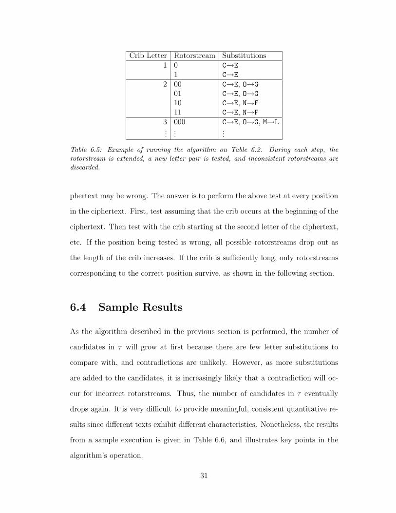
Crib Letter Rotorstream Substitutions1 0 C→E
1 C→E
2 00 C→E, O→G
01 C→E, O→G
10 C→E, N→F
11 C→E, N→F
3 000 C→E, O→G, M→L...
......
Table 6.5: Example of running the algorithm on Table 6.2. During each step, therotorstream is extended, a new letter pair is tested, and inconsistent rotorstreams arediscarded.
phertext may be wrong. The answer is to perform the above test at every position
in the ciphertext. First, test assuming that the crib occurs at the beginning of the
ciphertext. Then test with the crib starting at the second letter of the ciphertext,
etc. If the position being tested is wrong, all possible rotorstreams drop out as
the length of the crib increases. If the crib is sufficiently long, only rotorstreams
corresponding to the correct position survive, as shown in the following section.
6.4 Sample Results
As the algorithm described in the previous section is performed, the number of
candidates in τ will grow at first because there are few letter substitutions to
compare with, and contradictions are unlikely. However, as more substitutions
are added to the candidates, it is increasingly likely that a contradiction will oc-
cur for incorrect rotorstreams. Thus, the number of candidates in τ eventually
drops again. It is very difficult to provide meaningful, consistent quantitative re-
sults since different texts exhibit different characteristics. Nonetheless, the results
from a sample execution is given in Table 6.6, and illustrates key points in the
algorithm’s operation.
31

Crib Crib PositionLength 0 1 2 3 4 5 6 7 8 9 10 11 12 13 14 15 16
2 2 1 2 2 2 2 2 2 2 2 2 2 2 2 2 2 14 2 2 2 3 4 4 4 4 3 4 4 4 4 4 2 2 26 6 6 4 8 16 8 8 8 8 12 16 16 6 6 6 6 88 4 2 6 2 4 1 7 2 5 12 5 3 10 3 7 8 10
10 10 5 4 2 12 6 6 11 6 4 23 5 7 16 1412 2 4 3 2 4 3 8 5 37 8 3 11 1714 2 1 31 4 316 2 57 318 8720 10122 3024 4226 2428 1230 4
......
Table 6.6: Results from a sample algorithm execution. Values represent the number ofconsistent rotorstreams (whose lengths are one less than the crib length) found usingvarying crib lengths and different positions. Truncated rotorstreams are used becausethe last rotorstream bit has no effect until the next crib letter is considered. Tests thatresult in zero valid candidates are left blank.
In this example, 12 is the correct position of the crib within the text. It is
clear from the table that for all the other (incorrect) positions, the candidates are
all quickly eliminated. For every position, the number of candidates first increases
and then decreases as the crib length grows. This agrees with the expectations
outlined above. The table has been cropped to only show the most relevant data.
This initial cryptanalytic attack shows that a sufficiently long crib is generally
able to recover a unique substitution corresponding to the rotor internal wiring,
and the movement of the rotor during encryption. As mentioned previously, it is
difficult to draw quantitative conclusions from the tests performed because crib
lengths required to narrow down the number of possibilities to one vary depending
on the nature of the text being examined.
32
i 9 10 11 12 13 14 15 16 17 18 · · · 19 20 19 20 · · · 21 22 23 24 25ai 0 0 0 1 1 1 1 1 0 0 1 0 0 1 0 1 0 0 1Ai 5 5 5 5 6 7 8 9 10 10 10 11 10 10 11 11 12 12 12xi M A N C E E V A L U A T A T I O N O F
xi − Ai H V I X Y X N R B K Q I Q J X D B C Tyi − Ai I C O B N B H S W L D O D P B R W E Z
yi N H T G T I P B G V · · · N Z N Z · · · M C I Q L
i 26 27 28 29 30 31 32 33 34 35 36 37 38 39 40 41 42 43 44 45 46ai 1 0 1 0 0 0 1 1 1 0 1 0 1 1 1 1 1 1 1 0Ai 13 14 14 15 15 15 15 16 17 18 18 19 19 20 21 22 23 24 25 26 26xi C O M P U T E R C O M M U N I C A T I O N
xi − Ai P A Y A F E P B L W U T B T N G D V J O Nyi − Ai F Q N Q Y T F W K V X Z W Z H U R C P G H
yi S E B F N I U M B N P S P T C Q O A O G H
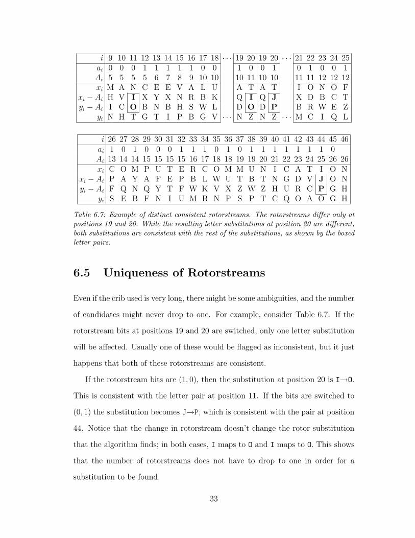
Table 6.7: Example of distinct consistent rotorstreams. The rotorstreams differ only atpositions 19 and 20. While the resulting letter substitutions at position 20 are different,both substitutions are consistent with the rest of the substitutions, as shown by the boxedletter pairs.
6.5 Uniqueness of Rotorstreams
Even if the crib used is very long, there might be some ambiguities, and the number
of candidates might never drop to one. For example, consider Table 6.7. If the
rotorstream bits at positions 19 and 20 are switched, only one letter substitution
will be affected. Usually one of these would be flagged as inconsistent, but it just
happens that both of these rotorstreams are consistent.
If the rotorstream bits are (1, 0), then the substitution at position 20 is I→O.
This is consistent with the letter pair at position 11. If the bits are switched to
(0, 1) the substitution becomes J→P, which is consistent with the pair at position
44. Notice that the change in rotorstream doesn’t change the rotor substitution
that the algorithm finds; in both cases, I maps to O and I maps to O. This shows
that the number of rotorstreams does not have to drop to one in order for a
substitution to be found.
33

yi −Bi?= yj −Bj xi − Ai
?= xj − Aj Ai −Bi
?= Aj −Bj Test Result
= = = consistent= 6= 6= consistent6= = 6= consistent6= 6= = consistent6= 6= 6= consistent= = 6= inconsistent= 6= = inconsistent6= = = inconsistent
Table 6.8: Consistency test for two-rotor encryption.
6.6 Extending this Technique
This strategy could also be applied to more than one cipher rotor. If, for example,
there are two rotors, then Equation 2.2 becomes
yi −Bi = π2
(π1(xi − Ai) + Ai −Bi
)(6.3)
Since the wiring π does not change, Equation 6.3 implies the following consis-
tency test for two plaintext-ciphertext letter pairs at positions i and j:
yi −Bi = yj −Bj ⇐⇒ π1(xi − Ai) + Ai −Bi = π1(xj − Aj) + Aj −Bj (6.4)
The consistency test is now more complex because there are three equalities
to check for; the right hand side depends on the equality of the difference between
rotor positions as well as the equality of the shifted plaintext letters. For example,
if both xi −Ai = xj −Aj and Ai −Bi = Aj −Bj but yi −Bi 6= yj −Bj, the only
possibility is that there is an inconsistency in the rotor wiring, and so the test
will return inconsistent. The results of the revised consistency test are shown in
Table 6.8.
Using the new consistency test proceeds as described above for the one-rotor
34

case by gradually extending rotorstreams and discarding inconsistent examples.
Naturally, the crib lengths required would be expected to increase as more rotors
are added. At some point, the amount of crib required renders the attack imprac-
tical. Thus, this method of extending the one-rotor attack was not carried out
completely, but rather a new attack strategy was devised.
35

Chapter 7
Cryptanalyzing 2- and 3-rotor
SIGABA
7.1 Attack Model
This attack assumes that a SIGABA machine along with its rotors has been
captured or reproduced. However, it assumes that the official key list used for
setting up the SIGABA is not known. The attack will be able to recover the order
and initial positions of the cipher rotors.
Once again, this attack does not attempt to model or recover details pertaining
to the stepping maze; the movements of each rotor will be assumed to be controlled
by a random number generator. A successful attack against this model thus
not only compromises the SIGABA but also any SIGABA-like rotor machine
regardless of what causes the rotor movements.
For the one-rotor case, the plaintext was assumed to be simply a concatenation
of English words. However, plaintext in the SIGABA is transformed so that every
letter Z becomes an X and every space becomes a Z. Thus, a plaintext that reads
36
THE ZEBRA ZIGZAGS would be transformed to THEZXEBRAZXIGXAGS just before it
is encrypted. To emulate this behavior, the letter Z is used to delimit words for
this attack.
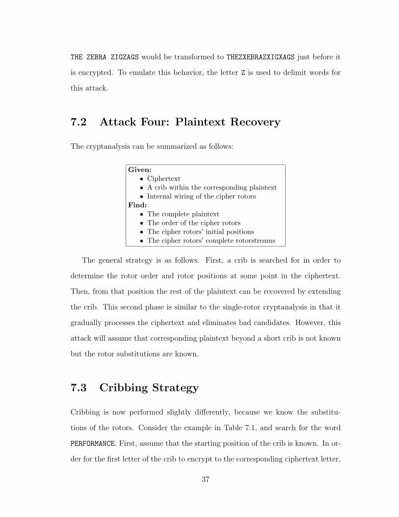
7.2 Attack Four: Plaintext Recovery
The cryptanalysis can be summarized as follows:
Given:• Ciphertext• A crib within the corresponding plaintext• Internal wiring of the cipher rotors
Find:• The complete plaintext• The order of the cipher rotors• The cipher rotors’ initial positions• The cipher rotors’ complete rotorstreams
The general strategy is as follows. First, a crib is searched for in order to
determine the rotor order and rotor positions at some point in the ciphertext.
Then, from that position the rest of the plaintext can be recovered by extending
the crib. This second phase is similar to the single-rotor cryptanalysis in that it
gradually processes the ciphertext and eliminates bad candidates. However, this
attack will assume that corresponding plaintext beyond a short crib is not known
but the rotor substitutions are known.
7.3 Cribbing Strategy
Cribbing is now performed slightly differently, because we know the substitu-
tions of the rotors. Consider the example in Table 7.1, and search for the word
PERFORMANCE. First, assume that the starting position of the crib is known. In or-
der for the first letter of the crib to encrypt to the corresponding ciphertext letter,
37

xi T H E Z P E R F O R M A N C E Z E V A L U A T I O N Zyi D W A A W K F F E I C P K O Y X A G C B V L B Q E C Y
Table 7.1: Example of encrypting two cipher rotors. For every plaintext letter xi, thecorresponding ciphertext letter yi is given below it.
the cipher rotors must be in one of possibly several orientations that produce the
desired substitution. In the example, the first crib letter is P, the corresponding
ciphertext letter is W, and there must be some set of rotor positions that produce
the substitution P→W. As an arbitrary example, (A4 = 1, B4 = 4) could be a set
of rotor positions that would result in the desired substitution using the given ci-
pher rotors. Store all such possibilities, and continue with the next crib-ciphertext
letter pair, E→K.
For each of the stored possibilities, the rotors may have advanced in one of four
ways (a4, b4) to arrive at this new state: (0,0), (0,1), (1,0), and (1,1). However, it
is extremely likely that some of these new states will not be consistent with the
new letter pair. For example, (A5 = 2, B5 = 5) is a set of rotor positions that
will encrypt the letter E to K for some rotors, but (A5 = 1, B5 = 5) will perform
some other (inconsistent) substitution. Whenever a set of rotor positions results
in a substitution that is inconsistent with the plaintext and ciphertext letter pairs
(e.g. E6→K at position 5), it is discarded. Consistent examples are kept under
consideration for the next letter pair. After all the letters in the crib have been
processed this way, the rotor position possibilities that remain are those that could
encrypt the crib to the ciphertext using the given rotors.
Of course, the crib might appear anywhere (or not at all) within the ciphertext.
If the position that is being tested is incorrect, then there will be many more
inconsistencies between the rotor substitutions and the crib-ciphertext letter pairs.
With a sufficiently long crib, the possibilities at incorrect ciphertext positions will
38
all be eliminated, leaving only those corresponding to the actual location of the
crib.
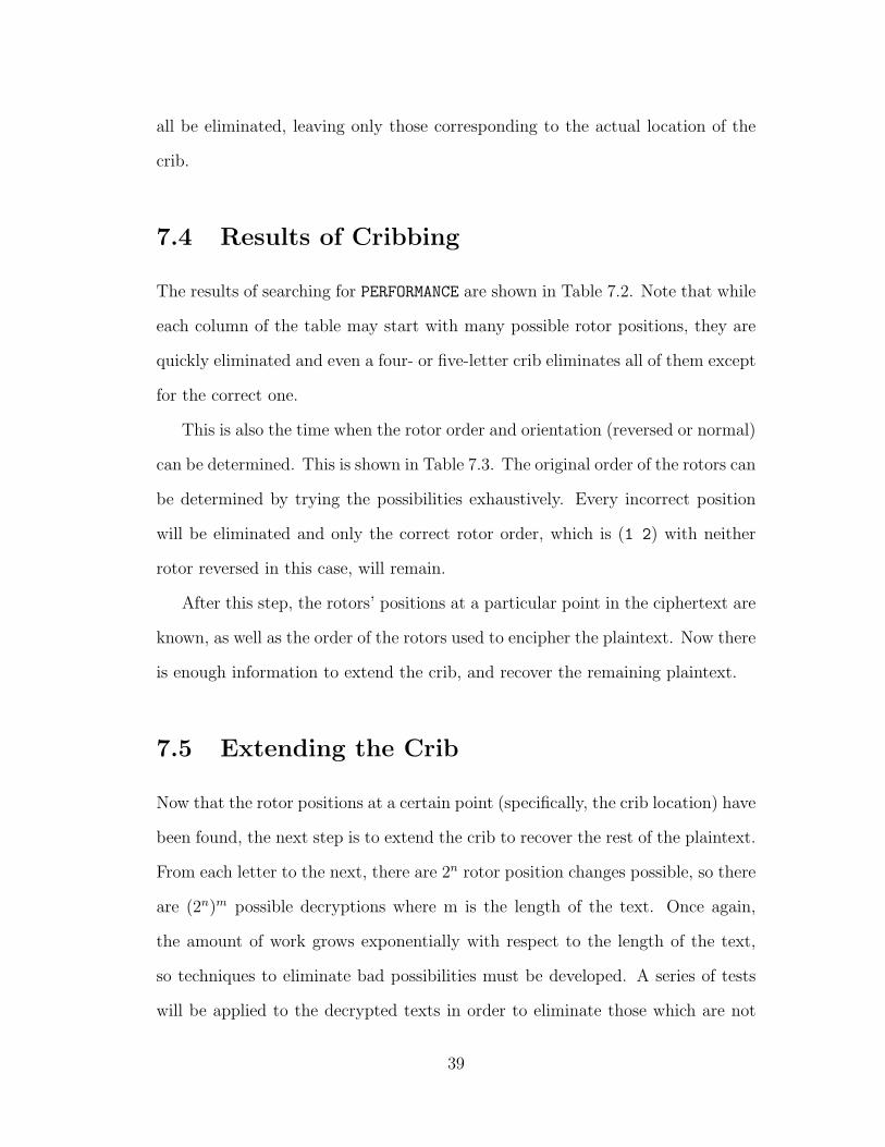
7.4 Results of Cribbing
The results of searching for PERFORMANCE are shown in Table 7.2. Note that while
each column of the table may start with many possible rotor positions, they are
quickly eliminated and even a four- or five-letter crib eliminates all of them except
for the correct one.
This is also the time when the rotor order and orientation (reversed or normal)
can be determined. This is shown in Table 7.3. The original order of the rotors can
be determined by trying the possibilities exhaustively. Every incorrect position
will be eliminated and only the correct rotor order, which is (1 2) with neither
rotor reversed in this case, will remain.
After this step, the rotors’ positions at a particular point in the ciphertext are
known, as well as the order of the rotors used to encipher the plaintext. Now there
is enough information to extend the crib, and recover the remaining plaintext.
7.5 Extending the Crib
Now that the rotor positions at a certain point (specifically, the crib location) have
been found, the next step is to extend the crib to recover the rest of the plaintext.
From each letter to the next, there are 2n rotor position changes possible, so there
are (2n)m possible decryptions where m is the length of the text. Once again,
the amount of work grows exponentially with respect to the length of the text,
so techniques to eliminate bad possibilities must be developed. A series of tests
will be applied to the decrypted texts in order to eliminate those which are not
39
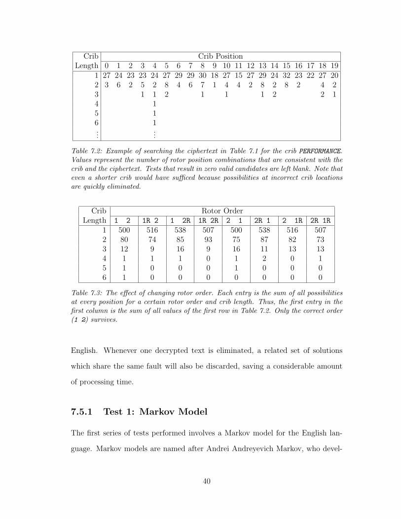
Crib Crib PositionLength 0 1 2 3 4 5 6 7 8 9 10 11 12 13 14 15 16 17 18 19
1 27 24 23 23 24 27 29 29 30 18 27 15 27 29 24 32 23 22 27 202 3 6 2 5 2 8 4 6 7 1 4 4 2 8 2 8 2 4 23 1 1 2 1 1 1 2 2 14 15 16 1...
...
Table 7.2: Example of searching the ciphertext in Table 7.1 for the crib PERFORMANCE.Values represent the number of rotor position combinations that are consistent with thecrib and the ciphertext. Tests that result in zero valid candidates are left blank. Note thateven a shorter crib would have sufficed because possibilities at incorrect crib locationsare quickly eliminated.
Crib Rotor OrderLength 1 2 1R 2 1 2R 1R 2R 2 1 2R 1 2 1R 2R 1R
1 500 516 538 507 500 538 516 5072 80 74 85 93 75 87 82 733 12 9 16 9 16 11 13 134 1 1 1 0 1 2 0 15 1 0 0 0 1 0 0 06 1 0 0 0 0 0 0 0
Table 7.3: The effect of changing rotor order. Each entry is the sum of all possibilitiesat every position for a certain rotor order and crib length. Thus, the first entry in thefirst column is the sum of all values of the first row in Table 7.2. Only the correct order(1 2) survives.
English. Whenever one decrypted text is eliminated, a related set of solutions
which share the same fault will also be discarded, saving a considerable amount
of processing time.
7.5.1 Test 1: Markov Model
The first series of tests performed involves a Markov model for the English lan-
guage. Markov models are named after Andrei Andreyevich Markov, who devel-
40
oped the underlying theory in the first part of the 20th century [NIS]. A Markov
model can be thought of as a weighted directed graph or a finite state machine
with weighted state transitions. When applied to a natural language such as En-
glish, states represent letters or words. Once a model is developed, a string known
as a Markov chain can be tested against the model to determine the resemblance
of that string to the model. If the model is good and the resemblance is high,
there is a high chance that the string is in the language from which the model was
derived.
Creating the Model
Generating a Markov model requires a large amount of text from the target lan-
guage. An n-gram is any string n characters long. Since the model is based upon
the probabilities of n-grams, using a larger sample of text reduces the chance
that irregularities in the sample will greatly affect the model. For example, if the
source text for modeling English was the sample “The YYY Company,” the model
would mistakenly believe that the 3-gram “YYY” was a common occurrence in
normal English. However, if the source was a novel that only mentioned the com-
pany name a few times, occurrences of “YYY” would be overshadowed by more
common 3-grams such as “the.”
For this project, the source sample consists of various English novels. Elec-
tronic versions of these were obtained primarily through Project Gutenberg [Gut],
which makes public domain texts available over the Internet. The works used total
nearly 6 million characters, of which 5.6 million are letters and spaces. Multiple
consecutive whitespace characters are treated as a single space, and punctuation
is ignored.
The second primary parameter that defines the Markov model is the size of
41
the n-gram it considers. First-order Markov models are built using 1-grams and 2-
grams, second-order models use 2-grams and 3-grams, etc. More complex models
represent the language more accurately, but they require exponentially increasing
storage to hold their data. A second-order model seemed to be a reasonable
compromise.
First, the absolute frequencies (counts) of all 2-grams and 3-grams were de-
termined by scanning all of the sample text. The counts of 2-grams and 3-grams
are stored, respectively, in
count(i, j) count(i, j, k) 0 ≤ i, j, k ≤ 26
Note that the space is given the ordinal position 26, and the English letters
are given ordinal positions 0 through 25 as before. Then, the following equation
was used to generate the relative probability of finding any 2-gram of letters and
spaces:
twograms =∑i,j
count(i, j)
π(i, j) =count(i, j)
twograms0 ≤ i, j ≤ 26 (7.1)
Next, the conditional probabilities for 3-grams are calculated. The following
is the probability of seeing the letter k, given that the letters i and j were just
seen:
P (k/(i, j)) =count(i, j, k)
count(i, j)0 ≤ i, j, k ≤ 26 (7.2)
Equations 7.1 and 7.2 form the Markov model.
42
Using a Markov model
Once a model X is generated, the probability of a string S = (s0, s1, . . . , sm−1)
occurring can be tested against the model as follows:
Pr(X0 = s0, . . . , Xm−1 = sm−1) = π(s0, s1)m−1∏i=2
P (si/(si−2, si−1)) (7.3)
The higher the resulting value, the closer that S matches the model. As the
crib is extended to different strings, each string’s score is updated by multiplying
by the conditional probability of the new character. At every step the lowest
scores, as determined by a threshold value, are discarded.
Problems
A variety of problems can occur when using a Markov model. First of all, a false
positive would be a non-English string that scores as high as English strings. Real
English text is not generated by a Markov model, so even strings with a high score
might not be valid. For example, all the three-grams in THEANGRIBL are relatively
common but it is not a word, so it will score unreasonably high.
Secondly, false negatives are possible. An English sentence such as “The YYY
Company finds zygotes” might have a low score because “YYY” does not normally
appear in English, and the word “zygote” has unusual trigrams. If the source the
model is derived from does not include the 3-gram “YYY” at all, then the score
will be zero from multiplying by zero in Equation 7.3. Even if all trigrams are
accounted for in the model, sufficiently many unusual trigrams will lower the score
with respect to other strings, even if those strings are not the actual plaintext.
Then, the valid but unusual sentence would be discarded as being non-English.
To help fix these problems, there are a variety of solutions. To help minimize
43
false negatives, a large sample of text should be used to generate the Markov
model and the threshold should be raised if it discards the valid strings. To deal
with false positives, more tests can be applied to the strings that pass the Markov
test.
7.5.2 Test 2: pspell
While the Markov test is able to weed out decrypted strings that are unlikely to
be English, it still lets many non-English strings pass. The second phase of testing
involves a spell checker to verify that the decrypted text is in English.
The tool used is the pspell interface to the aspell utility, which is gradually
replacing ispell as the spell checking utility on Unix platforms [asp]. When a Z is
detected, the letters read since the previous Z are sent to the spell checker. If the
result is not an English word, the string is discarded, and the surviving strings
are extended as described above.
Once again, the spell checker is susceptible to both false positives and false
negatives. For example, the string “fast dog hello the very” consists of valid
English words, but it is very unlikely to be the correct plaintext. A much bigger
problem is a false negative because the real plaintext is discarded. For example,
the word SIGABA is not in the standard pspell dictionary, so this thesis would
not pass a pspell test even if everything was spelled correctly.
False negatives can be fixed by using a custom word list. Words in the custom
list are accepted by the spell checker as being correct, in addition to the master
list. This is difficult if nothing is known about the text, but just as cribbing
makes guesses about the text and guessing cribs becomes easier as different texts
are compromised, developing a custom word list is not an insurmountable task.
44

7.5.3 Test 3: Customization
There are many strings that will pass the above tests. If the texts are sufficiently
small (50–100 characters), then the resulting strings may be searched by hand to
see which of them may be the correct plaintext. For longer texts, even pspell lets
too much through and the number of successful strings becomes unmanageable.
The problem gets even worse when three cipher rotors are used, because every
new letter added gives 23 = 8 new possibilities instead of four.
For the last step, we implemented two things. First of all, the main pspell
word list can be completely replaced by a custom list. This means that many
words that aren’t expected due to the context of the document will be weeded
out as opposed to being left in as false positives. In addition, we allow the user to
interact with the program, and manually weed out texts such as “fast dog hello
the very” before they get extended during the following steps, wasting processing
power unnecessarily.
After implementing these different steps, the number of decrypted texts re-
mains small enough so that they can be checked manually, and the correct plain-
text can be determined.
7.6 Notes Regarding Performance and Extend-
ing the Technique
As more of the tests described above are added, the processing power required
increases. In addition, the amount of work required increases at least exponentially
as more cipher rotors are added. Consider the initial cribbing step. Some sample
timings are given in Table 7.4. All tests were performed on a typical 800MHz
desktop computer. The addition of each rotor introduces a factor of roughly 40
45
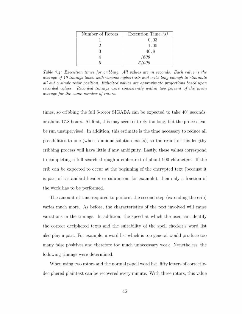
Number of Rotors Execution Time (s)1 0.032 1.053 40.84 16005 64000
Table 7.4: Execution times for cribbing. All values are in seconds. Each value is theaverage of 10 timings taken with various ciphertexts and cribs long enough to eliminateall but a single rotor position. Italicized values are approximate projections based uponrecorded values. Recorded timings were consistently within two percent of the meanaverage for the same number of rotors.
times, so cribbing the full 5-rotor SIGABA can be expected to take 403 seconds,
or about 17.8 hours. At first, this may seem entirely too long, but the process can
be run unsupervised. In addition, this estimate is the time necessary to reduce all
possibilities to one (when a unique solution exists), so the result of this lengthy
cribbing process will have little if any ambiguity. Lastly, these values correspond
to completing a full search through a ciphertext of about 900 characters. If the
crib can be expected to occur at the beginning of the encrypted text (because it
is part of a standard header or salutation, for example), then only a fraction of
the work has to be performed.
The amount of time required to perform the second step (extending the crib)
varies much more. As before, the characteristics of the text involved will cause
variations in the timings. In addition, the speed at which the user can identify
the correct deciphered texts and the suitability of the spell checker’s word list
also play a part. For example, a word list which is too general would produce too
many false positives and therefore too much unnecessary work. Nonetheless, the
following timings were determined.
When using two rotors and the normal pspell word list, fifty letters of correctly-
deciphered plaintext can be recovered every minute. With three rotors, this value
46

drops to about one letter per minute with the standard pspell word list. When
the word list is replaced with something more appropriate, the speed increases to
about two to four characters a minute. This new word list was derived by taking
the union of all words that appeared in the ciphertexts used for this project.
It would be possible to extend these techniques for two and three rotors to
attack and defeat the full five-rotor SIGABA. The difference will be more pos-
sibilities generated with the addition of new cipher rotors, which in turn would
require more computer power or more streamlined tests to eliminate them.
Nonetheless, this is an effective attack because it only needs a very small crib.
While it does require human interaction or knowledge of a word list specific to
the subject of the text, this makes it less prone to stalling caused by an explosion
of false positives, especially if the user can monitor the progress and interact with
the program to influence its decryption path.
47

Chapter 8
Conclusion
In this thesis, an overview of the SIGABA and its history was made, a review of
the existing cryptanalytic work on the SIGABA was conducted, and new crypt-
analytic methods were introduced. The methods discussed include a brute force
technique, known plaintext attacks, and a known ciphertext attack with crib-
bing. The new attacks have been used to successfully defeat cryptosystems of
up to three rotors. The cryptosystem model used for the cryptanalysis is general
enough that defeating it not only defeats the SIGABA, but also defeats any cryp-
tosystem where the rotors move according to any pseudorandom source. Lastly,
methods that can be used to extend these attacks were considered. As a result of
this work, the SIGABA and related rotor-based cryptosystems can be considered
compromised.
48

Bibliography
[Arm49] Department of the Army. Crypto-Operating Instructions for ASAM 1/1,1949. Available from http://www.maritime.org/ecminst.htm.
[asp] GNU aspell. Available from http://aspell.net/.
[CSE] Communications Security Establishment. An Overview of the His-tory of Cryptography. Available on the Internet from http://www.cse-cst.gc.ca/en/documents/about cse/museum.pdf.
[Gut] Project gutenberg. Available from http://www.gutenberg.org/.
[NIS] National Institute of Standards and Technology. Dictionary of Al-gorithms and Data Structures. Available on the Internet fromhttp://www.nist.gov/dads/HTML/markovchain.html.
[NSA] National cryptologic museum. Available on the Internet fromhttp://www.nsa.gov/museum/big.html.
[Pek01] Richard S. Pekelney. SIGABA – ECM mark II, 2001. Available fromhttp://webhome.idirect.com/ jproc/crypto/ecm2.html.
[Pek02] Richard S. Pekelney. USS pampanito – ECM mark II, 2002. Availablefrom http://www.maritime.org/ecm2.htm.
[Sch96] Bruce Schneier. Applied Cryptography. John Wiley & Sons Inc., secondedition, 1996.
[SG90] Rok Sosic and Jun Gu. A polynomial time algorithm for the N -queensproblem. SIGART Bulletin, 1(3):7–11, October 1990.
[SP99] John J. G. Savard and Richard S Pekelney. The ECM mark II: Design,history, and cryptology. Cryptologia, XXIII(3), July 1999.
[SS01] Laurance F. Safford and Donald W. Seiler. Control circuits for electriccoding machines. United States Patent Number 6,175,625, January 2001.
49