Ultrasonic based distance meter
41
A Mini Project Report on “ULTRASONIC DISTANCE METER” submitted in partial fulfillment of the requirement for the award of degree of BACHELOR OF TECHNOLOGY in ELECTRONICS AND COMMUNICATION ENGINEERING submitted by P.UTTEJ KUMAR 12M61A04A2 Under the Guidance of Mr. Mohammad Hafizzudin M.Tech Assistant Professor DEPARTMENT OF ELECTRONICS & COMMUNICATION ENGINEERING SWARNA BHARATHI INSTITUTE OF SCIENCE & TECHNOLOGY, KHAMMAM (Approved by AICTE, Govt. of A.P. & Affiliated to JNTUH, Hyderabad) (2015-16)
-
Upload
uttej-kumar-palavai -
Category
Engineering
-
view
376 -
download
12
Transcript of Ultrasonic based distance meter
A Mini Project Report
on “ULTRASONIC DISTANCE METER”
submitted in partial fulfillment of the
requirement for the award of degree of BACHELOR OF TECHNOLOGY
in ELECTRONICS AND COMMUNICATION ENGINEERING
submitted by
P.UTTEJ KUMAR 12M61A04A2
Under the Guidance of Mr. Mohammad Hafizzudin M.Tech
Assistant Professor
DEPARTMENT OF ELECTRONICS & COMMUNICATION ENGINEERING
SWARNA BHARATHI INSTITUTE OF SCIENCE & TECHNOLOGY, KHAMMAM (Approved by AICTE, Govt. of A.P. & Affiliated to JNTUH, Hyderabad)
(2015-16)

Department of Electronics & Communication Engineering Swarna Bharathi Institute of Science & Technology, Khammam
(Approved by AICTE, Govt. of A.P. & Affiliated to JNTUH, Hyderabad)
CERTIFICATE
This is to certify that the project report entitled “ULTRASONIC
DISTANCE METER” is a bonafide record of work carried out by
P.UTTEJ KUMAR 12M61A04A2 We hereby accord our approval of it as a project work carried out and
presented in a manner required for its acceptance in partial fulfillment for the award of degree of BACHELOR OF TECHNOLOGY in ELECTRONICS AND COMMUNICATION ENGINEERING of Jawaharlal Nehru Technological University Hyderabad, Hyderabad during the academic year 2015-2016.
External Examiner
INTERNAL GUIDE Mr. Mohammad Hafizzudin M.Tech, Assistant Professor
PRINCIPAL Prof. P. Krishna Murthy M.Tech., Ph.D,
HEAD OF THE DEPARTMENT Mr.Gandham Srinivasa Rao M.Tech, MIEEE, Associate Professor

ACKNOWLEDGEMENT I take the opportunity to express my deep sense of gratitude to my Project guide,
Mr. Mohammad Hafizzudin, Assistant Professor, Department of ECE, Swarna Bharathi Institute of Science & Technology, Khammam, for his excellent guidance, technical information and support which helped me in successfully completing this project report.
I take the opportunity to express my heartfelt thanks to the Head of the Department Mr. Gandham Srinivasa Rao, Associate Professor, Department of Electronics & Communication Engineering, Swarna Bharathi Institute of Science & Technology, Khammam, for his excellent guidance, technical information and support which helped me in successfully completing this project.
I wish to express my profound thanks to Prof. P. Krishna Murthy, Principal, Swarna Bharathi Institute of Science & Technology, Khammam, for providing necessary facilities to make this project a success.
I thank all the members of Teaching and Non-Teaching Staff, Department of ECE, and all those who have helped me directly or indirectly in completing my project successfully.
UTTEJ KUMAR PALAVAI 12M61A04A2

DECLARATION
I declare that the project entitled “ULTRASONIC DISTANCE METER” recorded in this report does not form part of any other thesis on which a degree has been awarded earlier. I further declare that this project report is based on my work carried out at the “SWARNA BHARATHI INSTITUTE OF SCIENCE & TECHNOLOGY”, Khammam during the B.Tech course. DATE: PLACE: Khammam
Reported by,
Mr.UTTEJ KUMAR PALAVAI 12M61A04A2

ABSTRACT Ultrasonic Distance Meter working principle is based on ultrasonic waves.
As the human ear’s audible perception range is 20 Hz to 20 kHz, it is Insensitive to ultrasonic waves, and hence the ultrasound waves can be used for applications in industries/vehicles without hindering human activity. The distance can be measured using pulse echo and phase measurement method. The signal is transmitted by an ultrasonic transducer, reflected by an obstacle and received by another transducer where the signal is detected. The time delay of the transmitted and the received signal corresponds to the distance between the system and the obstacle. A common use of ultrasound is for range finding. Sonar works similarly to radar. An ultrasonic pulse is generated in a particular direction. If there is an object in the way of this pulse, the pulse is reflected back to the sender as an echo and is detected. Measuring the difference in time between the pulse transmitted and the echo received, it is possible to determine how far away the object is. Bats use a variety of ultrasonic ranging (echolocation) to detect their prey.
The application area of the Ultrasonic Distance Meter is very wide in rescue operations, spy robot, versatile use in autonomous technology, use in mining; it has found essential use in light industry (e.g. Toy industry) agriculture, used in car parking systems and all other engineering practices.
INDEX
CONTENTS PAGE NO
1. INTRODUCTION 1 2. HISTORY AND CIRCUIT DIAGRAM 3 2.1 History 4 2.2 Circuit Diagram 5 3. IMPLEMENTATION 6 3.1 Design Implementation 6 3.1.1 ATMEGA8 Microcontroller 6 3.1.2 Ultrasonic Sensor 17 3.1.3 Liquid Crystal Display 20 3.1.4 Buzzer 22 3.1.5 Voltage Regulator 23 3.2 Software Requirement 23 3.2.1 AVR STUDIO Overview 24 3.2.2 PROTUES Overview 24 3.2.3 PROGISP Overview 25 4. BLOCK DIAGRAM AND OUTPUT 26 4.1 Block Diagram 26 4.2 Sample Output 27
5. ADVANTAGES 28 5.1 Advantages 28 5.2 Limitations 28 6. SOURCE CODE 29 7. CONCLUSION 32 8. BIBLIOGRAPHY 33 9. PROJECT OUTLOOK 34

LIST OF FIGURES 1.1 Electronic Distance Measurement 2 2.1 Measuring Using Scales 4 2.2 Traditional Measuring Devices 5 2.3 Circuit Diagram 5 3.1 Atmega8 Microcontroller 8 3.2 Pin Diagram of Atmega8 Microcontroller 11 3.3 Block Diagram of Atmega8 Microcontroller 12 3.4 AVR Status Register 13 3.5 AVR CPU General Purpose Working Registers 15 3.6 Ultrasonic Sensor 17 3.7 Measuring the Distance Using Ultrasonic Sensor 19 3.8 Timing Diagram of the Sensor 20 3.9 LCD Screen 21 3.10 Power Supply Connection to LCD 22 3.11 Buzzer 22 3.12 Pin Diagram of Voltage Regulator 23 4.1 Block Diagram 26 4.2 PCB Design Used For the Project 27
CHAPTER 1
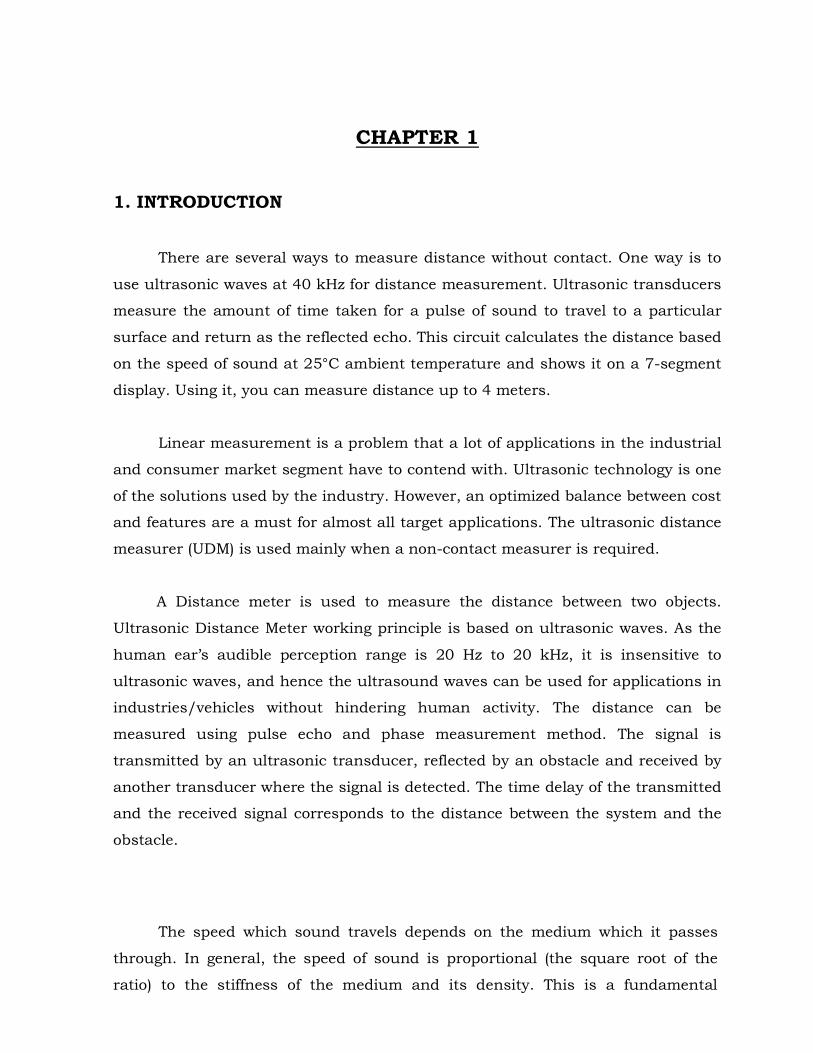
1. INTRODUCTION
There are several ways to measure distance without contact. One way is to use ultrasonic waves at 40 kHz for distance measurement. Ultrasonic transducers measure the amount of time taken for a pulse of sound to travel to a particular surface and return as the reflected echo. This circuit calculates the distance based on the speed of sound at 25°C ambient temperature and shows it on a 7-segment display. Using it, you can measure distance up to 4 meters.
Linear measurement is a problem that a lot of applications in the industrial and consumer market segment have to contend with. Ultrasonic technology is one of the solutions used by the industry. However, an optimized balance between cost and features are a must for almost all target applications. The ultrasonic distance measurer (UDM) is used mainly when a non-contact measurer is required.
A Distance meter is used to measure the distance between two objects. Ultrasonic Distance Meter working principle is based on ultrasonic waves. As the human ear’s audible perception range is 20 Hz to 20 kHz, it is insensitive to ultrasonic waves, and hence the ultrasound waves can be used for applications in industries/vehicles without hindering human activity. The distance can be measured using pulse echo and phase measurement method. The signal is transmitted by an ultrasonic transducer, reflected by an obstacle and received by another transducer where the signal is detected. The time delay of the transmitted and the received signal corresponds to the distance between the system and the obstacle.
The speed which sound travels depends on the medium which it passes
through. In general, the speed of sound is proportional (the square root of the ratio) to the stiffness of the medium and its density. This is a fundamental
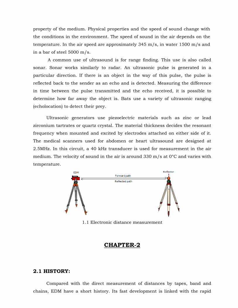
property of the medium. Physical properties and the speed of sound change with the conditions in the environment. The speed of sound in the air depends on the temperature. In the air speed are approximately 345 m/s, in water 1500 m/s and in a bar of steel 5000 m/s. A common use of ultrasound is for range finding. This use is also called sonar. Sonar works similarly to radar. An ultrasonic pulse is generated in a particular direction. If there is an object in the way of this pulse, the pulse is reflected back to the sender as an echo and is detected. Measuring the difference in time between the pulse transmitted and the echo received, it is possible to determine how far away the object is. Bats use a variety of ultrasonic ranging (echolocation) to detect their prey.
Ultrasonic generators use piezoelectric materials such as zinc or lead zirconium tartrates or quartz crystal. The material thickness decides the resonant frequency when mounted and excited by electrodes attached on either side of it. The medical scanners used for abdomen or heart ultrasound are designed at 2.5MHz. In this circuit, a 40 kHz transducer is used for measurement in the air medium. The velocity of sound in the air is around 330 m/s at 0°C and varies with temperature.
1.1 Electronic distance measurement
CHAPTER-2
2.1 HISTORY:
Compared with the direct measurement of distances by tapes, band and chains, EDM have a short history. Its fast development is linked with the rapid
progress in electronics during this century. The availability of relatively cheap instruments was only possible due to the rapid progress which has been made in solid state electronics since the early 1970s.
The development of the first light wave EDM instrument is connected with the name of the Swedish scientist E.Bergstrand. He designed the First Geodetic meter (short form of GEOdetic distance METER) for the determination of the velocity of light in 1943. The commercial instrument Geodimeter NASM-2 became available in 1950, produced by a large Swedish manufacturer of chemicals, AGA. With the early Geodimeters, longer distances could only be measured at night. The latest long-range Geodimeters, models 600 and 8, are at present in wide use in geodetic surveying throughout the world. The first EDM instrument using radio waves was developed by T.L. Wadley at the National Institute of Telecommunications Research of South Africa in 1954. It became available under the name Tellurometer in 1957. Its range exceeded that of the Geodimeter and it was therefore in much wider use until lasers were introduced in EDM late in the 1960's.
The first prototypes of short range EDM instruments (incorporating luminescence diodes) appeared in the mid 1960's (Tellurometer MA 100 in 1965; Zeiss SM 11 in 1967). These instruments have been commercially released since the late 1960's (Wi Id/Secret Distomat DI 10 in 1968; Tellurometer MA 100 in 1969; Zeiss SM 11 in 1970). Short range instruments with infrared (I R) light sources are now increasingly used for all types of surveys; long range instruments are used for the measurement of geodetic networks.
Two other groups also need be mentioned. The most precise EDM instrument to date, the Mekometer, was built by K.D.Froome and R.H.Bradsell in 1961 at the National Physical Laboratory, Teddington (U.K.) and became commercially available early in 1973. On short distances, accuracies of 0.2 mm can be achieved.
The first electronic tachometer (sometimes termed "total station"), the Zeiss (Oberkochen) Reg E1 to 14, became available in 1970 and featured electronic readout not only of distance but also of the vertical and horizontal circles. The second total station, the AGA Geodimeter 700 became available in 1971.
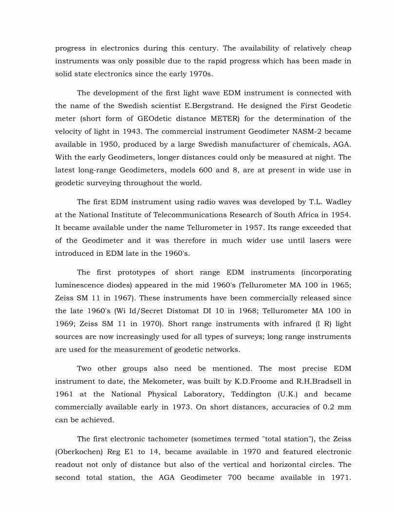
Electronic tachometers have a great future in large scale detail surveys, especially if combined with electronic booking and computerized data processing and plotting.
2.1 Measuring using scales
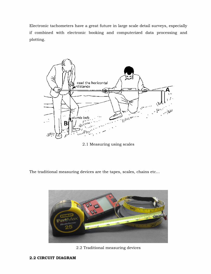
The traditional measuring devices are the tapes, scales, chains etc…
2.2 Traditional measuring devices
2.2 CIRCUIT DIAGRAM
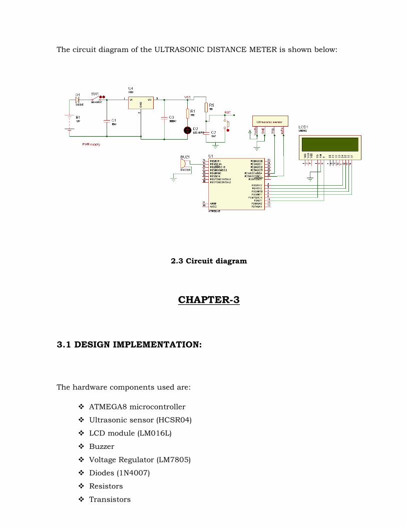
The circuit diagram of the ULTRASONIC DISTANCE METER is shown below:
2.3 Circuit diagram
CHAPTER-3
3.1 DESIGN IMPLEMENTATION: The hardware components used are:
ATMEGA8 microcontroller Ultrasonic sensor (HCSR04) LCD module (LM016L) Buzzer Voltage Regulator (LM7805) Diodes (1N4007) Resistors Transistors

Capacitors Switch
3.1.1 ATMEGA8 MICROCONTROLLER Definition of a Microcontroller
Microcontroller, as the name suggests, are small controllers. They are like single chip computers that are often embedded into other systems to function as processing/controlling unit. For example, the remote control you are using probably has microcontrollers inside that do decoding and other controlling functions. They are also used in automobiles, washing machines, microwave ovens, toys ... etc., where automation is needed.
The key features of microcontrollers include:
High Integration of Functionality Microcontrollers sometimes are called single-chip computers because they
have on-chip memory and I/O circuitry and other circuitries that enable them to function as small standalone computers without other supporting circuitry.
Field Programmability, Flexibility Microcontrollers often use EEPROM or EPROM as their storage device to
allow field programmability so they are flexible to use. Once the program is tested to be correct then large quantities of microcontrollers can be programmed to be used in embedded systems.
Easy to Use
Assembly language is often used in microcontrollers and since they usually follow RISC architecture, the instruction set is small. The development package of microcontrollers often includes an assembler, a simulator, a programmer to "burn" the chip and a demonstration board. Some packages include a high level language compiler such as a C compiler and more sophisticated libraries.
Most microcontrollers will also combine other devices such as:
A Timer module to allow the microcontroller to perform tasks for certain time periods.

A serial I/O port to allow data to flow between the microcontroller and other devices such as a PC or another microcontroller.
An ADC to allow the microcontroller to accept analogue input data for processing.
ATMEGA8 microcontroller is used in this project:
The Atmel AVR core combines a rich instruction set with 32 general purpose working registers. All the 32 registers are directly connected to the Arithmetic Logic Unit (ALU), allowing two independent registers to be accessed in one single instruction executed in one clock cycle. The resulting architecture is more code efficient while achieving throughputs up to ten times faster than conventional CISC microcontrollers.
3.1 Atmega8 Microcontroller
The ATmega8 provides the following features: 8 Kbytes of In-System Programmable Flash with Read-While-Write capabilities, 512 bytes of EEPROM, 1 Kbyte of SRAM, 23 general purpose I/O lines, 32 general purpose working registers, three flexible Timer/Counters with compare modes, internal and external interrupts, a serial programmable USART, a byte oriented Two- wire Serial Interface, a 6-channel ADC (eight channels in TQFP and QFN/MLF packages) with 10-bit accuracy, a programmable Watchdog Timer with Internal Oscillator, an SPI serial port, and five software selectable power saving modes. The Idle mode stops the CPU while allowing the SRAM; Timer/Counters, SPI port,

and interrupt system to continue functioning. The Power- down mode saves the register contents but freezes the Oscillator, disabling all other chip functions until the next Interrupt or Hardware Reset. In Power-save mode, the asynchronous timer continues to run, allowing the user to maintain a timer base while the rest of the device is sleeping. The ADC Noise Reduction mode stops the CPU and all I/O modules except asynchronous timer and ADC, to minimize switching noise during ADC conversions. In Standby mode, the crystal/resonator Oscillator is running while the rest of the device is sleeping. This allows very fast start-up combined with low-power consumption. The device is manufactured using Atmel’s high density non-volatile memory technology. The Flash Program memory can be reprogrammed In-System through an SPI serial interface, by a conventional non-volatile memory programmer, or by an On-chip boot program running on the AVR core. The boot program can use any interface to download the application program in the Application Flash memory. Software in the Boot Flash Section will continue to run while the Application Flash Section is updated, providing true Read-While-Write operation. By combining an 8-bit RISC CPU with In-System Self-Programmable Flash on a monolithic chip, the Atmel ATmega8 is a powerful microcontroller that provides a highly-flexible and cost-effective solution to many embedded control applications. The ATmega8 is supported with a full suite of program and system development tools, including C compilers, macro assemblers, program debugger/simulators, In-Circuit Emulators, and evaluation kits. The high-performance Atmel AVR ALU operates in direct connection with all the 32 general purpose working registers. Within a single clock cycle, arithmetic operations between general purpose registers or between a register and an immediate are executed. The ALU operations are divided into three main categories – arithmetic, logical, and bit-functions. Some implementations of the architecture also provide a powerful multiplier supporting both signed/unsigned multiplication and fractional format.
Key features
High-performance, Low-power Atmel AVR 8-bit Microcontroller. Advanced RISC Architecture 130 Powerful Instructions – Most Single-clock Cycle Execution 32 × 8 General Purpose Working Registers

Fully Static Operation Up to 16MIPS Throughput at 16MHz On-chip 2-cycle Multiplier
High Endurance Non-volatile Memory segments. 8Kbytes of In-System Self-programmable Flash program memory 512Bytes EEPROM, 1Kbyte Internal SRAM Write/Erase Cycles: 10,000 Flash/100,000 EEPROM. Data retention: 20 years at 85°C/100 years at 25°C. Optional Boot Code Section with Independent Lock Bits. In-System Programming by On-chip Boot Program True Read-While-Write
Operation Programming Lock for Software Security Peripheral Features, Two 8-bit Timer/Counters with Separate Presale, one
Compare Mode One 16-bit Timer/Counter with Separate Pre scalar, Compare Mode, and
Capture Mode Real Time Counter with Separate Oscillator Three PWM Channels 8-channel ADC in TQFP and QFN/MLF package Eight Channels 10-bit
Accuracy. 6-channel ADC in PDIP package Six Channels 10-bit Accuracy Byte-oriented Two-wire Serial Interface. Programmable Serial USART. Master/Slave SPI Serial Interface. Programmable Watchdog Timer with Separate On-chip Oscillator. On-chip Analog Comparator Power-on Reset and Programmable Brown-out Detection Internal Calibrated RC Oscillator External and Internal Interrupt Sources Five Sleep Modes: Idle, ADC Noise Reduction, Power-save, Power-down, and
Standby 23 Programmable I/O Lines, 28-lead PDIP, 32-lead TQFP, and 32-pad
QFN/MLF.

2.7V - 5.5V (ATmega8L),4.5V - 5.5V (ATmega8) Power Consumption at 4Mhz, 3V, 25°C
PIN DIAGRAM The PIN diagram of the ATmega8 microcontroller is shown below:
3.2 Pin diagram of Atmega8 Microcontroller
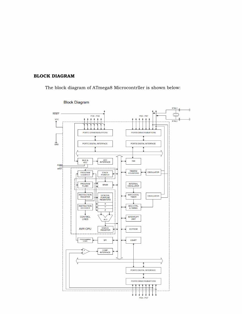
BLOCK DIAGRAM The block diagram of ATmega8 Microcontrller is shown below:
3.3 BLOCK DIAGRAM of ATMEGA8 MICROCONTROLLER
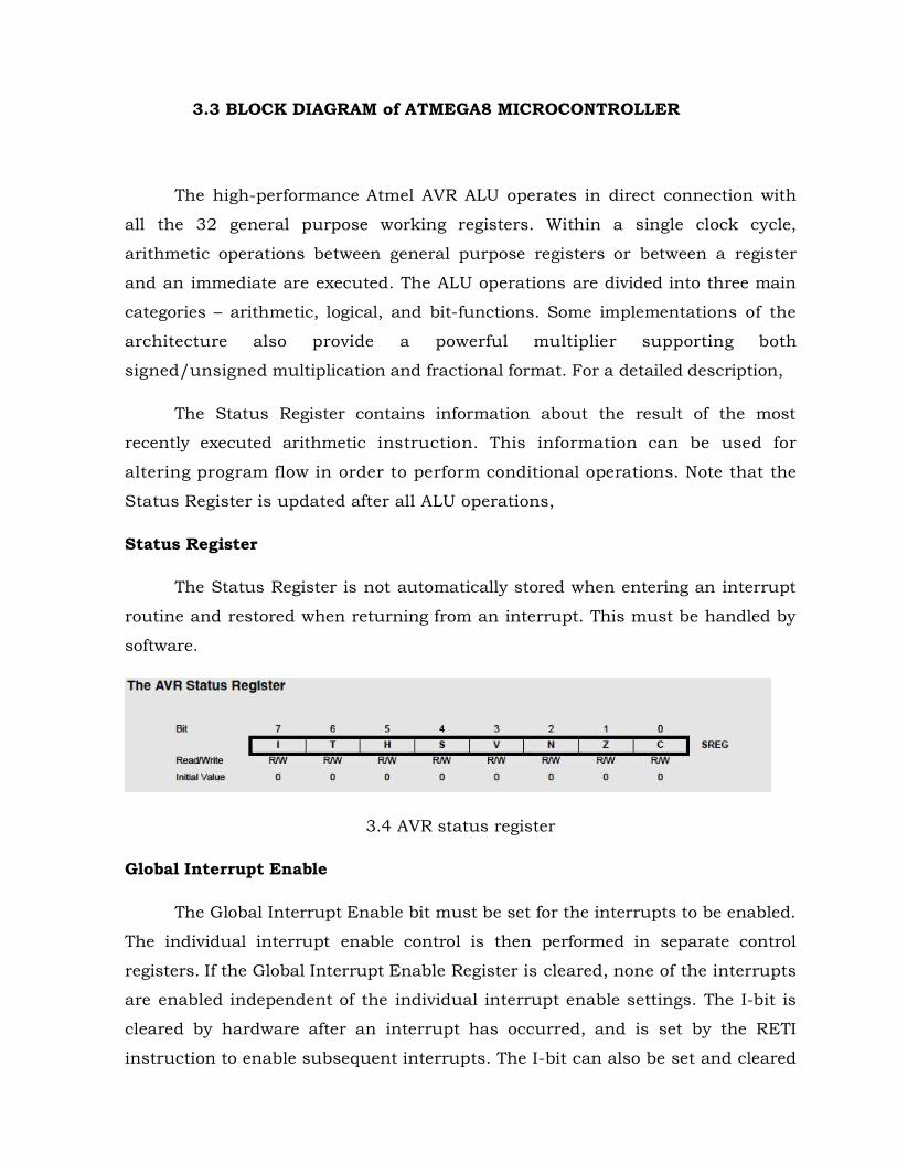
The high-performance Atmel AVR ALU operates in direct connection with all the 32 general purpose working registers. Within a single clock cycle, arithmetic operations between general purpose registers or between a register and an immediate are executed. The ALU operations are divided into three main categories – arithmetic, logical, and bit-functions. Some implementations of the architecture also provide a powerful multiplier supporting both signed/unsigned multiplication and fractional format. For a detailed description,
The Status Register contains information about the result of the most recently executed arithmetic instruction. This information can be used for altering program flow in order to perform conditional operations. Note that the Status Register is updated after all ALU operations, Status Register
The Status Register is not automatically stored when entering an interrupt routine and restored when returning from an interrupt. This must be handled by software.
3.4 AVR status register
Global Interrupt Enable The Global Interrupt Enable bit must be set for the interrupts to be enabled.
The individual interrupt enable control is then performed in separate control registers. If the Global Interrupt Enable Register is cleared, none of the interrupts are enabled independent of the individual interrupt enable settings. The I-bit is cleared by hardware after an interrupt has occurred, and is set by the RETI instruction to enable subsequent interrupts. The I-bit can also be set and cleared
by the application with the SEI and CLI instructions, as described in the Instruction Set Reference. Bit Copy Storage
The Bit Copy instructions BLD (Bit Load) and BST (Bit Store) use the T-bit as source or destination for the operated bit. A bit from a register in the Register File can be copied into T by the BST instruction, and a bit in T can be copied into a bit in a register in the Register File by the BLD instruction. Half Carry Flag
The Half Carry Flag H indicates a Half Carry in some arithmetic operations. Half Carry is useful in BCD arithmetic. Two’s Complement Overflow Flag
The Two’s Complement Overflow Flag V supports two’s complement arithmetic’s. Negative Flag
The Negative Flag N indicates a negative result in an arithmetic or logic operation. Zero Flag
The Zero Flag Z indicates a zero result in an arithmetic or logic operation. Carry Flag
The Carry Flag C indicates a Carry in an arithmetic or logic operation. General Purpose Register File
The Register File is optimized for the AVR Enhanced RISC instruction set. In order to achieve the required performance and flexibility, the following input/output schemes are supported by the Register File.
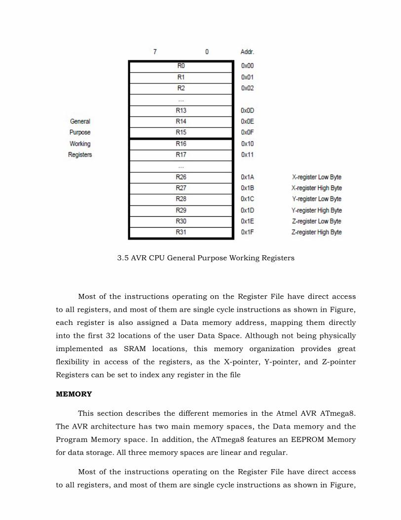
3.5 AVR CPU General Purpose Working Registers
Most of the instructions operating on the Register File have direct access
to all registers, and most of them are single cycle instructions as shown in Figure, each register is also assigned a Data memory address, mapping them directly into the first 32 locations of the user Data Space. Although not being physically implemented as SRAM locations, this memory organization provides great flexibility in access of the registers, as the X-pointer, Y-pointer, and Z-pointer Registers can be set to index any register in the file MEMORY
This section describes the different memories in the Atmel AVR ATmega8. The AVR architecture has two main memory spaces, the Data memory and the Program Memory space. In addition, the ATmega8 features an EEPROM Memory for data storage. All three memory spaces are linear and regular.
Most of the instructions operating on the Register File have direct access to all registers, and most of them are single cycle instructions as shown in Figure,

each register is also assigned a Data memory address, mapping them directly into the first 32 locations of the user Data Space. Although not being physically implemented as SRAM locations, this memory organization provides great flexibility in access of the registers, as the X-pointer, Y-pointer, and Z-pointer Registers can be set to index any register in the file. In-System Reprogrammable Flash memory
The ATmega8 contains 8Kbytes On-chip In-System Reprogrammable Flash memory for pro- gram storage. Since all AVR instructions are 16-bits or 32-bits wide, the Flash is organized as 4K × 16 bits. For software security, the Flash Program memory space is divided into two sections, Boot Program section and Application Program section.
The Flash memory has an endurance of at least 10,000 write/erase cycles. The ATmega8 Pro- gram Counter (PC) is 12 bits wide, thus addressing the 4K Program memory locations. The operation of Boot Program section and associated Boot Lock Bits for software protection are described in detail in “Boot Loader Support – Read-While-Write Self-Programming”. SRAM DATA MEMORY
The lower 1120 Data memory locations address the Register File, the I/O Memory, and the internal data SRAM. The first 96 locations address the Register File and I/O Memory, and the next 1024 locations address the internal data SRAM.
The five different addressing modes for the Data memory cover Direct, Indirect with Displacement, Indirect, Indirect with Pre-decrement, and Indirect with Post-increment. In the Register File, registers R26 to R31 feature the indirect addressing pointer registers. 3.1.2 ULTRASONIC SENSOR
Ultrasonic sensor ranging module HCSR04 provides 2cm-400cm non-contact measurement function, the ranging accuracy can reach to 3mm.the module includes ultrasonic transmitter, receiver and a control circuit.
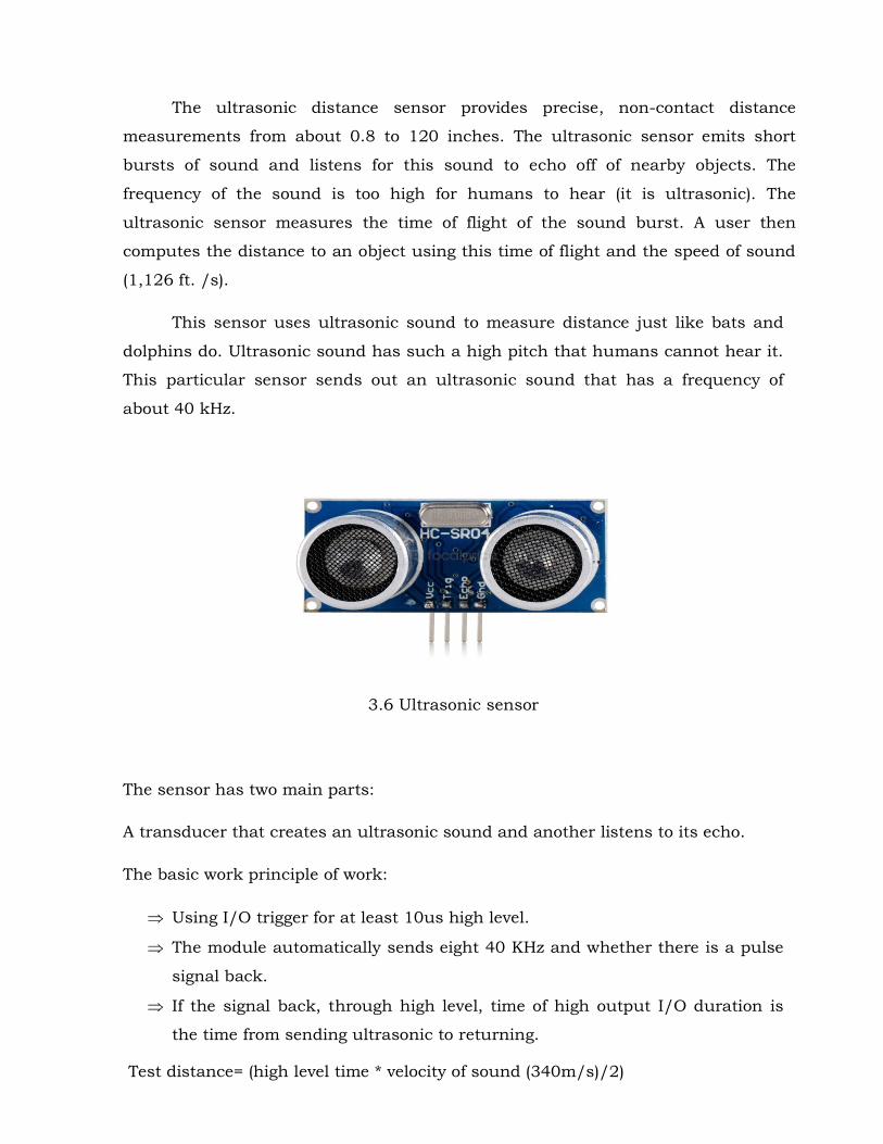
The ultrasonic distance sensor provides precise, non-contact distance measurements from about 0.8 to 120 inches. The ultrasonic sensor emits short bursts of sound and listens for this sound to echo off of nearby objects. The frequency of the sound is too high for humans to hear (it is ultrasonic). The ultrasonic sensor measures the time of flight of the sound burst. A user then computes the distance to an object using this time of flight and the speed of sound (1,126 ft. /s).
This sensor uses ultrasonic sound to measure distance just like bats and dolphins do. Ultrasonic sound has such a high pitch that humans cannot hear it. This particular sensor sends out an ultrasonic sound that has a frequency of about 40 kHz.
3.6 Ultrasonic sensor
The sensor has two main parts: A transducer that creates an ultrasonic sound and another listens to its echo. The basic work principle of work:
Using I/O trigger for at least 10us high level. The module automatically sends eight 40 KHz and whether there is a pulse
signal back. If the signal back, through high level, time of high output I/O duration is
the time from sending ultrasonic to returning. Test distance= (high level time * velocity of sound (340m/s)/2)

Sound travels at approximately 340 meters per second. This corresponds to about 29.412us (microseconds) per centimeter. To measure the distance the sound has travelled we use the formula:
Distance = (Time x Speed of Sound) / 2. The "2" is in the formula because the sound has to travel back and forth. First the sound travels away from the sensor, and then it bounces off of a surface and returns back. The easy way to read the distance as centimeters is use the formula:
Centimeters = ((Microseconds / 2) / 29). For example, if it takes 100us (microseconds) for the ultrasonic sound to bounce back, then the distance is ((100 / 2) / 29) centimeters or about 1.7 centimeters.
3.7 Measuring the Distance Using Ultrasonic Sensor
Wire connecting direct as following
5V Supply

Trigger Pulse Input Echo Pulse Output 0V Ground
Electric Parameters Working Voltage : DC 5 V Working Current : 15mA Working Frequency : 40Hz Max Range : 4m Min Range : 2cm Measuring Angle : 15 degree Trigger Input Signal : 10uS TTL pulse Echo output signal : input TTL lever signal & the range in proportion Dimension : 45*20*15mm
Timing diagram
The Timing diagram is shown below. You only need to supply a short 10uS pulse to the trigger input to start the ranging, and then the module will send out an 8 cycle burst of ultrasound at 40 kHz and raise its echo. The Echo is a distance object that is pulse width and the range in proportion .You can calculate the range through the time interval between sending trigger signal and receiving echo signal.
3.8 Timing diagram of the sensor

3.1.3 LIQUID CRYSTAL DISPLAY
LCD stands for Liquid Crystal Display. LCD is finding wide spread use replacing LEDs (seven segment LEDs or other multi segment LEDs) because of the following reasons:
1. The declining prices of LCDs. 2. The ability to display numbers, characters and graphics. This is in contrast
to LEDs, which are limited to numbers and a few characters. 3. Incorporation of a refreshing controller into the LCD, thereby relieving the
CPU of the task of refreshing the LCD. In contrast, the LED must be refreshed by the CPU to keep displaying the data.
4. Ease of programming for characters and graphics.
These components are “specialized” for being used with the microcontrollers, which means that they cannot be activated by standard IC circuits. They are used for writing different messages on a miniature LCD.
LM160L type liquid crystal display board is used here.
3.9 LCD screen
LCD screen

LCD screen consists of two lines with 16 characters each. Each character consists of 5x7 dot matrix. Contrast on display depends on the power supply voltage and whether messages are displayed in one or two lines. For that reason, variable voltage 0-Vdd is applied on pin marked as Vee. Trimmer potentiometer is usually used for that purpose the connections some versions of displays have built in backlight (blue or green diodes). When used during operating, a resistor for current limitation should be used (like with any LE diode).
3.10 Power supply connection to LCD
3.1.4 BUZZER
A buzzer or beeper is an audio signaling device, which may be mechanical, electromechanical or piezoelectric. Typical uses of buzzers and beepers include alarm devices, timers and confirmation of user input such as a mouse click or keystroke.
3.11 Buzzer
Electromechanical Early device were based on an electromechanical system identical to an
electric bell without the metal gong. Similarly a relay may be connected to

interrupt its own actuating current, causing the contacts to buzz. Often these units were anchored to a wall or ceiling to use it as a sounding board. The word “buzzer comes from the rasping noise that electromechanical buzzers made. Mechanical
A joy buzzer is an example of a purely mechanical buzzer. They require a driver. Piezoelectric
A Piezoelectric element may be driven by an oscillating electronic circuit or by other audio signal source, driven with a piezoelectric audio amplifier. Sounds commonly used to indicate that a button has been pressed are a click, a ring or a beep. 3.1.5 VOLTAGE REGULATOR
A Voltage regulator is designed to automatically maintain a constant voltage level. A Voltage regulator may be a simple “feed-forward” design or may include negative feedback control loops. It may use an electromechanical mechanism, or electronic components. Depending upon the design, it may be used to regulate one or more AC or DC voltages.

3.12 Pin diagram of voltage regulator 3.2 Software Requirements: AVR Studio Proteus ProgISP 3.2.1 AVR STUDIO Overview AVR stands for advanced virtual RISC.
AVR Studio, the popular Software, combines Project Management, Source
Code Editing, Program Debugging, and Flash Programming in a single, powerful environment.
Project Management, Device Setup, and Tool Configuration. Editor facilities for Creating, Modifying, and Correcting Programs. Target Debugging or CPU & Peripheral Simulation.
3.2.2 PROTEUS Overview PROTEUS stands for PROcesses and Transactions Editable by Users.
Proteus is simulation software for various designs with microcontroller. It is mainly popular because of availability of almost all microcontrollers in it. So it is a handy tool to test programs and embedded design as for electronics hobbyist. User can simulate his programming of microcontroller in Proteus simulation software.
After simulating your circuit in Proteus software user can directly make PCB design with it so it could be an all in one package for the clients.
3.2.3 PROGISP Overview: PROGISP stands for Project In System Programmer.
PROGISP is a way for, in system programming of micro controllers in controlled way.
Its development credit goes to Chi Fang Technology Co., Ltd, which engages in the design of embedded systems products, sharing and free software developing.
PROGISP supports for nearly 110 CPUs with on board by default fuse bits selection for every controller. It’s very friendly user interface with required graphics.

Chapter-4 4.1 Block diagram:
4.1 Block Diagram
SENSOR
ATMEGA8
MICRO CONTROLLER
POWER SUPPLY
LCD
BUZZER
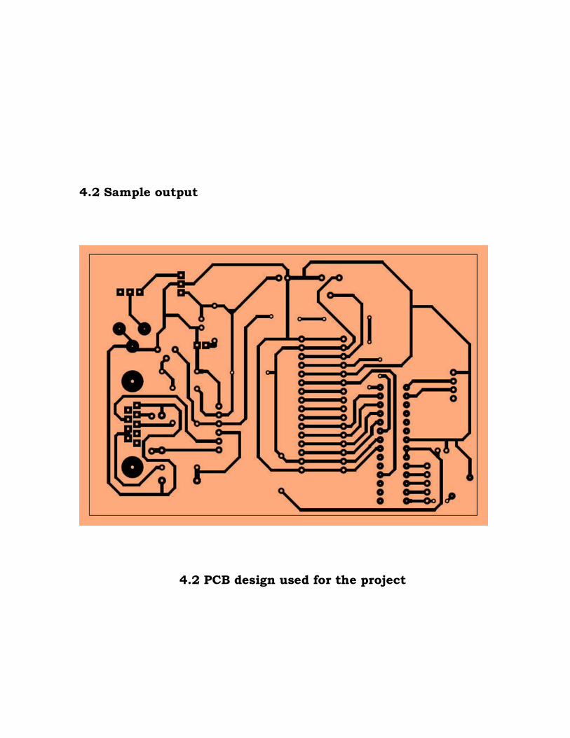
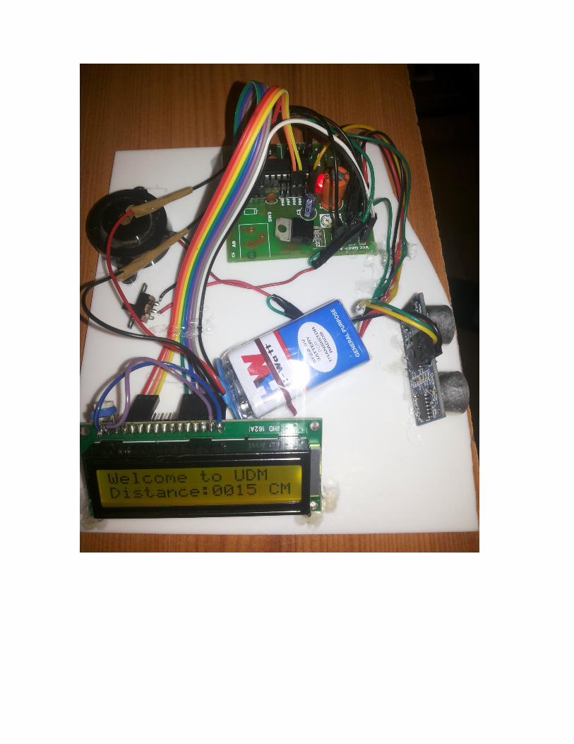
4.2 Sample output
4.2 PCB design used for the project

Chapter-5 5.1 Advantages:
Works very accurately. As it uses sound waves the operational speed is very high. It is when a non-contact measurer is required. Low cost.
5.2 Limitations:
The range of the ultrasonic sensor is low (=4m). The power level of the signal is too low for long range measurement.
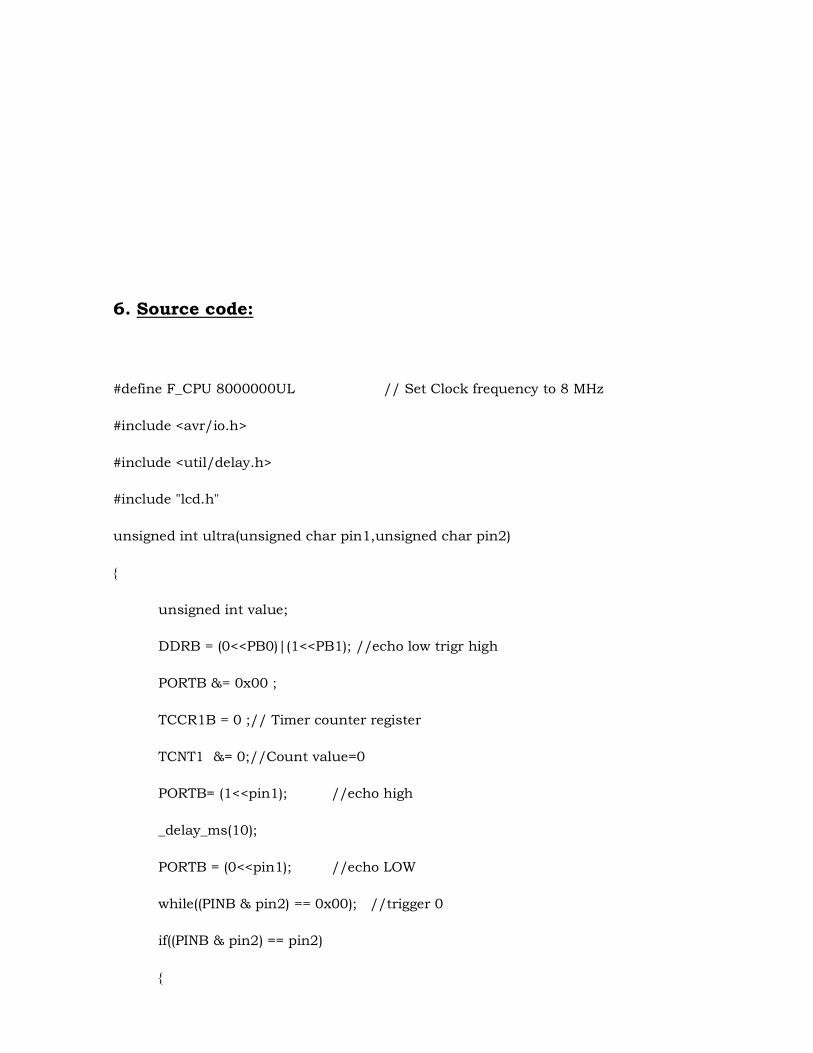
6. Source code: #define F_CPU 8000000UL // Set Clock frequency to 8 MHz #include <avr/io.h> #include <util/delay.h> #include "lcd.h" unsigned int ultra(unsigned char pin1,unsigned char pin2) { unsigned int value; DDRB = (0<<PB0)|(1<<PB1); //echo low trigr high PORTB &= 0x00 ; TCCR1B = 0 ;// Timer counter register TCNT1 &= 0;//Count value=0 PORTB= (1<<pin1); //echo high _delay_ms(10); PORTB = (0<<pin1); //echo LOW while((PINB & pin2) == 0x00); //trigger 0 if((PINB & pin2) == pin2) {
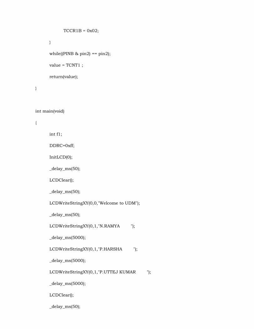
TCCR1B = 0x02; } while((PINB & pin2) == pin2); value = TCNT1 ; return(value); } int main(void) { int f1; DDRC=0xff; InitLCD(0); _delay_ms(50); LCDClear(); _delay_ms(50); LCDWriteStringXY(0,0,"Welcome to UDM"); _delay_ms(50); LCDWriteStringXY(0,1,"N.RAMYA "); _delay_ms(5000); LCDWriteStringXY(0,1,"P.HARSHA "); _delay_ms(5000); LCDWriteStringXY(0,1,"P.UTTEJ KUMAR "); _delay_ms(5000); LCDClear(); _delay_ms(50);
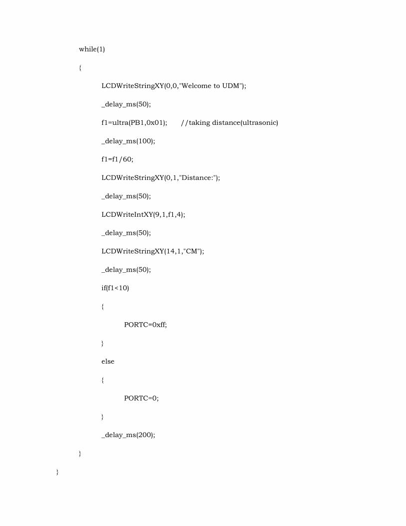
while(1) { LCDWriteStringXY(0,0,"Welcome to UDM"); _delay_ms(50); f1=ultra(PB1,0x01); //taking distance(ultrasonic) _delay_ms(100); f1=f1/60; LCDWriteStringXY(0,1,"Distance:"); _delay_ms(50); LCDWriteIntXY(9,1,f1,4); _delay_ms(50); LCDWriteStringXY(14,1,"CM"); _delay_ms(50); if(f1<10) { PORTC=0xff; } else { PORTC=0; } _delay_ms(200); } }

7. CONCLUSION:
Ultrasonic distance measurement is a convenient method compared to traditional one using measurement scales. This kind of measurement is particularly applicable to inaccessible areas where traditional means cannot be implemented such as high temperature, pressure zones etc.
The ultrasonic sensors have a great future scope as it is a non-contact distance measurer. The application area of the Ultrasonic Distance Meter is very wide in rescue operations, spy robot, versatile use in autonomous technology, use in mining; it has found essential use in light industry (e.g. Toy industry) agriculture, used in car parking systems and all other engineering practices.

8. BIBILIOGRAPHY: www.google.co.in www.wikipedia.com www.atmel.com/images/atmel-2486-8-bit-avr-microcontroller-
atmega8_l_datasheet.pdf www.micropik.com/pdf/HCSR04.pdf www.seminarsonly.com

9. PROJECT OUTLOCK