ultrasonic distance measurement
31
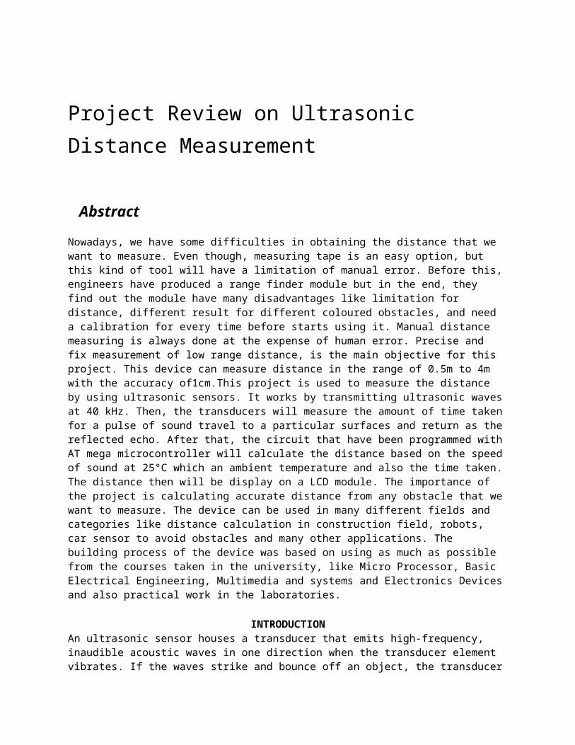
Project Review on Ultrasonic Distance Measurement Abstract Nowadays, we have some difficulties in obtaining the distance that we want to measure. Even though, measuring tape is an easy option, but this kind of tool will have a limitation of manual error. Before this, engineers have produced a range finder module but in the end, they find out the module have many disadvantages like limitation for distance, different result for different coloured obstacles, and need a calibration for every time before starts using it. Manual distance measuring is always done at the expense of human error. Precise and fix measurement of low range distance, is the main objective for this project. This device can measure distance in the range of 0.5m to 4m with the accuracy of1cm.This project is used to measure the distance by using ultrasonic sensors. It works by transmitting ultrasonic waves at 40 kHz. Then, the transducers will measure the amount of time taken for a pulse of sound travel to a particular surfaces and return as the reflected echo. After that, the circuit that have been programmed with AT mega microcontroller will calculate the distance based on the speed of sound at 25°C which an ambient temperature and also the time taken. The distance then will be display on a LCD module. The importance of the project is calculating accurate distance from any obstacle that we want to measure. The device can be used in many different fields and categories like distance calculation in construction field, robots, car sensor to avoid obstacles and many other applications. The building process of the device was based on using as much as possible from the courses taken in the university, like Micro Processor, Basic Electrical Engineering, Multimedia and systems and Electronics Devices and also practical work in the laboratories. INTRODUCTION An ultrasonic sensor houses a transducer that emits high-frequency, inaudible acoustic waves in one direction when the transducer element vibrates. If the waves strike and bounce off an object, the transducer
-
Upload
tj-ideaforinnovation -
Category
Technology
-
view
83 -
download
8
Transcript of ultrasonic distance measurement
Project Review on Ultrasonic Distance Measurement
AbstractNowadays, we have some difficulties in obtaining the distance that we want to measure. Even though, measuring tape is an easy option, but this kind of tool will have a limitation of manual error. Before this, engineers have produced a range finder module but in the end, they find out the module have many disadvantages like limitation for distance, different result for different coloured obstacles, and need a calibration for every time before starts using it. Manual distance measuring is always done at the expense of human error. Precise and fix measurement of low range distance, is the main objective for this project. This device can measure distance in the range of 0.5m to 4m with the accuracy of1cm.This project is used to measure the distance by using ultrasonic sensors. It works by transmitting ultrasonic waves at 40 kHz. Then, the transducers will measure the amount of time taken for a pulse of sound travel to a particular surfaces and return as the reflected echo. After that, the circuit that have been programmed with AT mega microcontroller will calculate the distance based on the speed of sound at 25°C which an ambient temperature and also the time taken. The distance then will be display on a LCD module. The importance of the project is calculating accurate distance from any obstacle that we want to measure. The device can be used in many different fields and categories like distance calculation in construction field, robots, car sensor to avoid obstacles and many other applications. The building process of the device was based on using as much as possible from the courses taken in the university, like Micro Processor, Basic Electrical Engineering, Multimedia and systems and Electronics Devices and also practical work in the laboratories.
INTRODUCTIONAn ultrasonic sensor houses a transducer that emits high-frequency, inaudible acoustic waves in one direction when the transducer element vibrates. If the waves strike and bounce off an object, the transducer receives the echoed signal. The sensor then determines its distance from the object based on the length of time between the initial sound burst and the echo's return. Ultrasonic sensors require fairly accurate timing circuitry, so acoustic sensors really require a processor of some sort to drive them. Ultrasonic sensors should be a first choice for detecting clear objects, liquids, dense materials of any surface type (rough, smooth, shiny) and irregular shaped objects. This makes them one of the most ideal choices for measuring the height of containers which could be of different shapes, sizes, color and material. The transmitter transmits the ultra sonic waves towards the object and according to the time taken by echo from the transmitter to object and object to receiver, the distance is calculated. If the obstacle is in the designated range the comparator sends the signal to microcontroller which in turn sends an output signal as shown through block diagram in
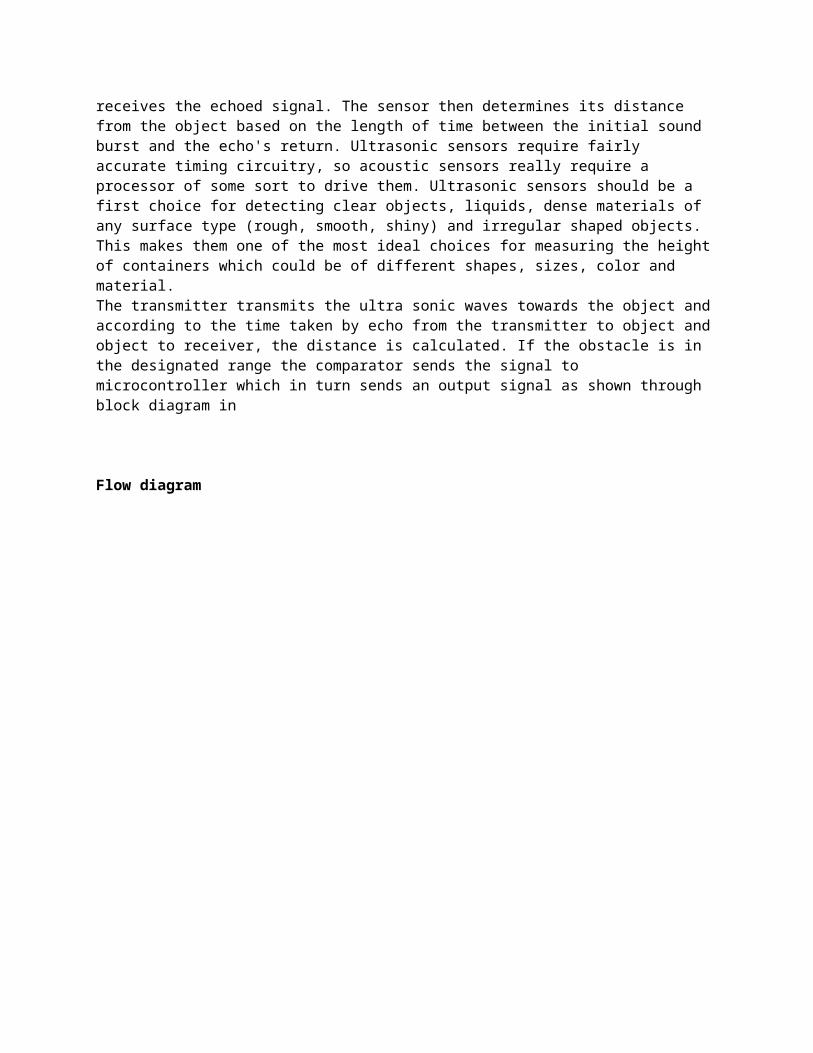
Flow diagram
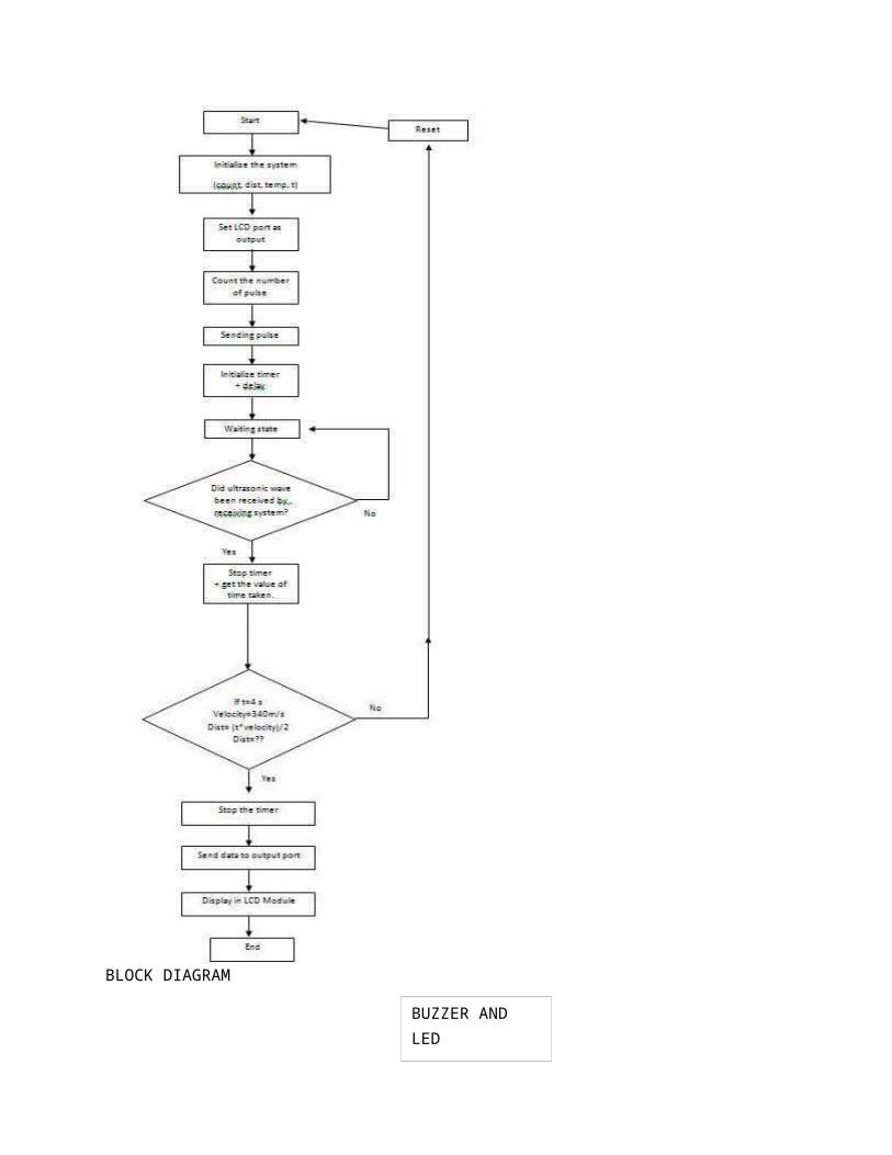
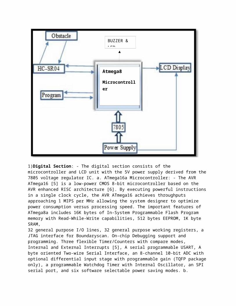
BLOCK DIAGRAM
Design Formulate Op-Amp gain formula: In the negative feedback mode of operation, operational amplifier gain is given by, AV = Rf / R1 PLL Center frequency: In PLL tone detector, the free-running frequency of the current controlled oscillator in the absence of an input signal, is known as center frequency, which is given by,
MICRO CONTROLLER SMPS 12V 1A
LCD 16X2
ULTRA SONIC SENSOR
BUZZER AND LED
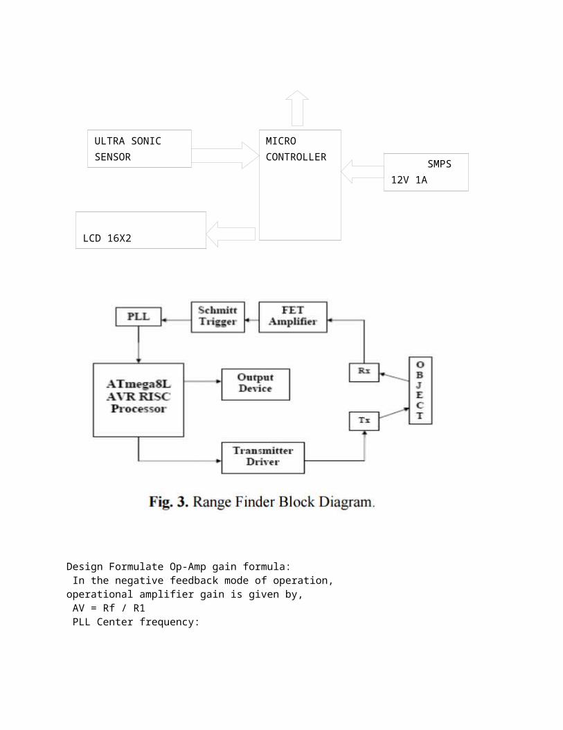
fO = 1 / (1.1 R1 C1) PLL Detection Bandwidth: The frequency range, centered about fO, within which an input signal above the threshold voltage (typically 20 mVRMS) will cause a logical zero state on the output. The detection bandwidth corresponds to the loop capture range.
BW (in % of fO) = 1070 V1 / (fO C1) Velocity of Sound in air: The velocity of sound, V, in gas such as air, for frequencies above 200 Hz is given by, V = √ (γρ / ℮), which is 332 m/s The velocity of sound for 1 µ sec is .34 mm.
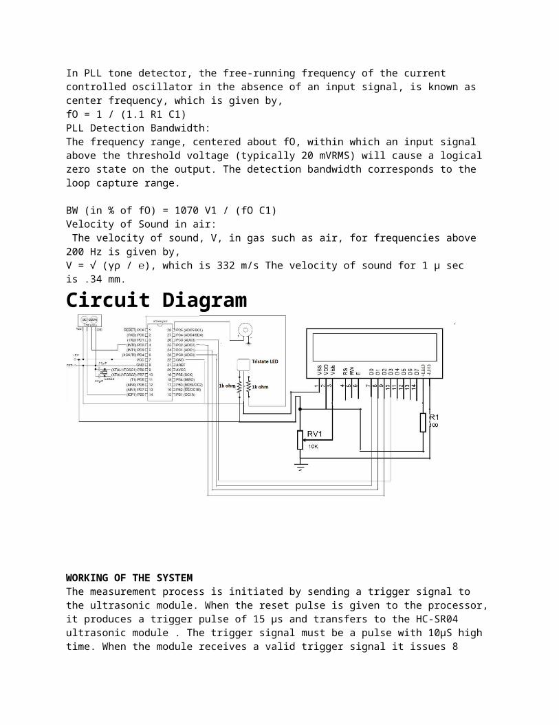
Circuit Diagram
WORKING OF THE SYSTEM The measurement process is initiated by sending a trigger signal to the ultrasonic module. When the reset pulse is given to the processor, it produces a trigger pulse of 15 µs and transfers to the HC-SR04 ultrasonic module . The trigger signal must be a pulse with 10µS high time. When the module receives a valid trigger signal it issues 8 pulses of 40 KHz ultrasonic sound from the transmitter. The echo of this sound is picked by the receiver, after getting the echo of the ultrasonic sound, the module produce a signal at the echo pin whose high time is proportional to the distance to be measured. Test distance = (high level time × velocity of sound (340M/S)) / 2 Distance in cm = echo pulse width in µs/58 Distance in inch = echo pulse width in µs/148 Finally the distance calculated based upon the pulse width of the echo signal is send to the LCD segment and the range is displayed in centimetres. This ultrasonic rangefinder can measure distances up to 2.5 meters at an accuracy of 0.1 centimetre.
METHODOLOGY The system design required familiarisation with adopted technologies for contactless range determination. The flaws in the infrared based system and the advantages of employing an ultrasonic wave based system was analysed in detail by referring to the systems designed based on these technologies. Comparisons were made and the technique was finalised. Extensive literature survey was conducted to determine the best suited components for the system to be fabricated. Program code [3] and the hardware design [4] were completed after considering the required system performance and the constraints like range temperature etc.
HARDWARE DESIGN The system hardware may be broadly classified into two sections i) Digital section and ii) Analog section. The basic hardware structure can be understood from conceptual block diagram is shown in Fig.
1)Digital Section: - The digital section consists of the microcontroller and LCD unit with the 5V power supply derived from the 7805 voltage regulator IC. a. ATmega16a Microcontroller: - The AVR ATmega16 [5] is a low-power CMOS 8-bit microcontroller based on the AVR enhanced RISC architecture [6]. By executing powerful instructions in a single clock cycle, the AVR ATmega16 achieves throughputs approaching 1 MIPS per MHz allowing the system designer to optimize power consumption versus processing speed. The important features of ATmega8a includes 16K bytes of In-System Programmable Flash Program memory with Read-While-Write capabilities, 512 bytes EEPROM, 1K byte SRAM,32 general purpose I/O lines, 32 general purpose working registers, a JTAG interface for Boundaryscan. On-chip Debugging support and programming. Three flexible Timer/Counters with compare modes, Internal and External Interrupts [5], A serial programmable USART, A byte oriented Two-wire Serial Interface, an 8-channel 10-bit ADC with optional differential input stage with programmable gain (TQFP package only), a programmable Watchdog Timer with Internal Oscillator, an SPI serial port, and six software selectable power saving modes. b. LCDisplay:- A 16x2 Liquid Crystal Display is a low power, low cost, basic electronic display.A 16x2 LCD means it can display 16 characters per line and there are 2 such lines. In this LCD each character is displayed in 5x7 pixel matrix. This LCD has two registers, namely, Command and Data. The command register stores the command instructions given to the LCD. A command is an instruction given to LCD to do a predefined task like initializing it, clearing its screen, setting the cursor position, controlling display etc. The data register stores the data to be displayed on the LCD. The data is the ASCII value of the character (measured distance) to be displayed on the LCD.
2)Analog Section:-The analog system consists of the ultrasonic module which consists of the ultrasonic transmitter and the receiver. a. HC-SR04 Ultrasonic Module: - HC-SR04 is an ultrasonic ranging module
Atmega8
Microcontroller
BUZZER & LED
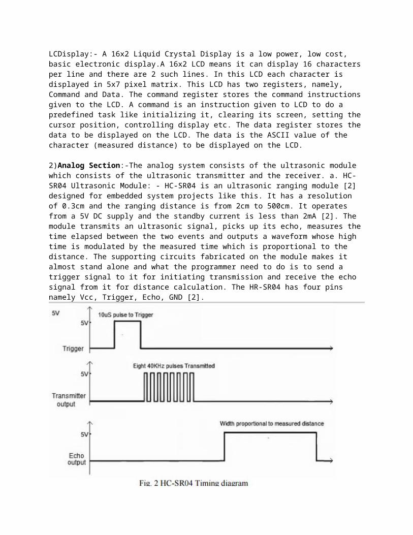
[2] designed for embedded system projects like this. It has a resolution of 0.3cm and the ranging distance is from 2cm to 500cm. It operates from a 5V DC supply and the standby current is less than 2mA [2]. The module transmits an ultrasonic signal, picks up its echo, measures the time elapsed between the two events and outputs a waveform whose high time is modulated by the measured time which is proportional to the distance. The supporting circuits fabricated on the module makes it almost stand alone and what the programmer need to do is to send a trigger signal to it for initiating transmission and receive the echo signal from it for distance calculation. The HR-SR04 has four pins namely Vcc, Trigger, Echo, GND [2].
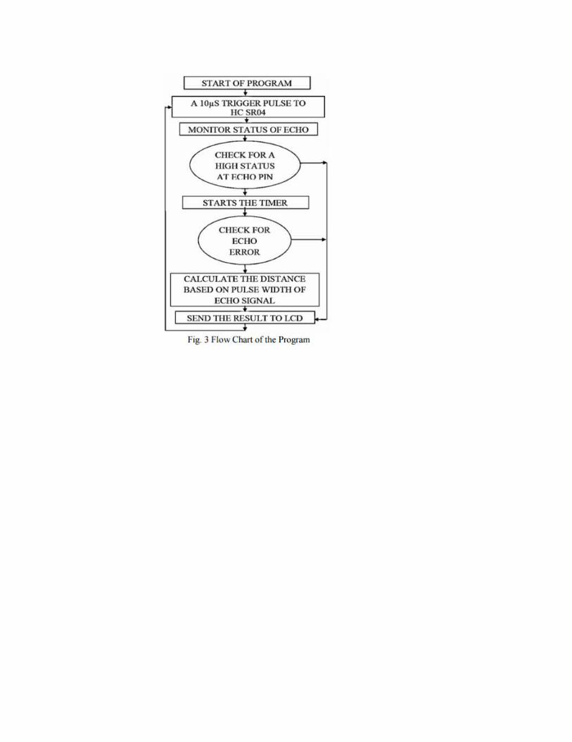
From the timing diagram, you can see that the 40 KHz pulse train is transmitted just after the 10uS triggering pulse and the echo output is obtained after some more time. The next triggering pulse can be given only after the echo is faded away and this time period is called cycle period. The cycle period for HC-SR04 must not be below 50mS. According to datasheet [2], the distance can be calculated from the echo pulse width using the following equations. Distance in cm = echo pulse width in µs/58 Distance in inch = echo pulse width in µs/148SOFTWARE DESIGN The program design for ATmega8 was done in C language [7]. It is easy to develop and implement Atmega16a program in C language [5] due to its flexibility, easiness of programming and debugging. The program [3] was burned to the ATmega8 microcontroller [4] using the USBASP programmer. The compilation of C language program to hex file was done using the popular GNU based WinAVR GCC [5]. It offers additional functionality of burning the program to the IC. The USBASP programmer [7] utilizes the In Serial Programming capability of AVR microcontrollers and thus makes it possible to program the IC real-time during development. The flow chart of the program is shown in Fig
Software and Hardware Requirement
Software system
It is a remedies which plays a main role over the project integrating, actuating the hardware with automatic manner ,the software required for development are mentioned below.
Hardware system
It is a group of electronic devices put together to achieve the physical actions with a automatic manner based on the requirement under repetitive manner of loop.
3.1 Software details
Below specified software are used in developing printed circuit board and firmware to cruise the
vehicle.
Eagle cad
Avr Studio
Sina programmer
3.1.1 Eagle cad
Eagle stand for Easy Applicable Graphical Layout Editor is a successful PCB programming tool
which is intended to satisfy the requirements of the expert planners of the system. For more than
25 years, this software tool has been the PCB plot device of choice for an immense number of
electronic setup planners and designers around the globe. With a tremendous and element
building and reinforce bunch and an expansive domain, EAGLE offers significantly more than
faultless circuit plot.
Features:
1. Can be extended up to 999 sheets for building a schematic design
2. For all the sheets there are pre-viewing of the icon
3. Easy sorting of the designed sheets by just dragging and dropping the sheets.
4. reflexive prompting of contact cross references
5. Effective regeneration of parts by copying.
6. There is stability between both the schematic and the layout that is maintained.
7. The details or the comments on the schematic and the board can be given where needed.
Eagle-software can be divided into 3 parts: 1. Schematic-editor. 2. Layout-editor 3. Auto-router.
1. Schematic editor: Here it grants us to make typical representation of any of our own
outline. The significant point is to give great records of the whole outline and even it
grants different clients to see effortlessly.
Features:
Each and every line of schematic contains about 999 sheets per layout.
Individual sheets is associated with preview-icon
The supply or the power connections are generated automatically.
When a schematic is designed, the board is generated consequently.
The advantage of the hierarchical feature of schematic is that it will permit to divide the
schematic design for easy analysis
2. Layout editor: Here we can make our own particular format for our own schematic
configuration. Here we can effectively put the segments as indicated by our necessities
and copper-follows can be steered between those parts.
Features:
4X4m is the size of each board
Even we can place surface-device components
Rotation can be possible in 360-degree
Texts/words can be placed according to our convenient
DRC is used to check for the wrong connections
3. Auto router: This is a capable device so as to point the copper ways between the 2 parts.
It prompts in giving fruitful results in time without influencing the control components. It
keeps running on the various applications.
Features:
0.02mm is the dimension of single grid
Possible to generate is changed by adjusting the price issues.
Buried-paths are supported here.
16-layers can be supported at a time
3.1.2 Avr StudioAtmel® AVR Studio® 5 is the Integrated Development Environment (IDE) for creating and
troubleshooting implanted Atmel AVR® applications.
Fig 3.1 Shows Front View of AVR Studio Version 5
The AVR Studio 5 IDE gives you a consistent and simple to-use environment to compose,
construct, and troubleshoot your C/C++ and constructing agent code. Which is utilized to
produce a hex document which is to composed to microcontroller with an assistance of developer
and developer programming.
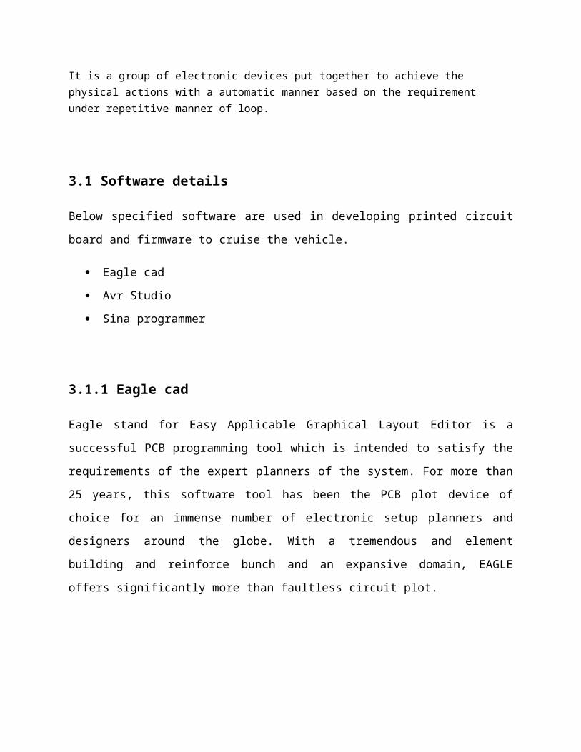
Steps involved to code and generate project hex file:
Step1:
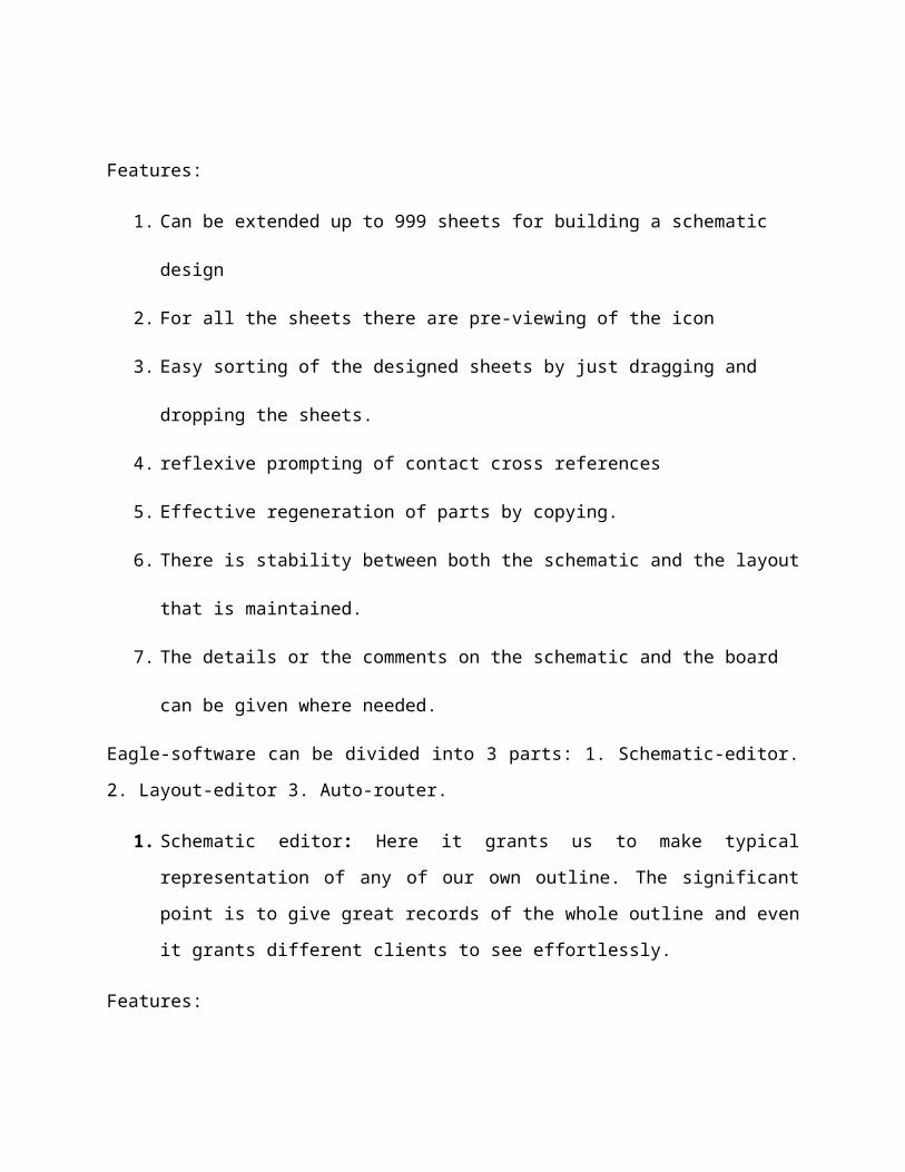
Fig3.2Create a New Project
Step 2:
Fig 3.3 Select the Target Device for Which the Hex File is to be generated
Step3:
Fig 3.4 Write Code With C.
Step4: click on run compile, no errors result.
Step5: build target generate hex file.
3.1.3 Sina-ProgrammerSinaProg is burner programming with straightforward client likewise consolidates an AVR Fuse
mini-computer.

Fig 3.5 Shows Front View of Sina Programmer
It utilizes enhanced AVRDUDE 5.10 and underpins new ic and new records just the accessible
ports and baud rate choice is conceivable. It is a standalone basic programming and no
establishment is select the ic sort as ATmega16 and set the Programmer to USB asp and port to
USB (as seen at the base of window).Click on browse under Hex File and find the .Hex
document to click Program button under bits can also be programmed .
3.2 Hardware Details
Following specified hardware components which include sensors, motors, and controller are
used in design of prototype.
Ultrasonic Sensor
L293d h-bridge motor driver
60rpm gear dc motor
Lcd 16x2
Battery
Atmega-8
POWER SUPPLY
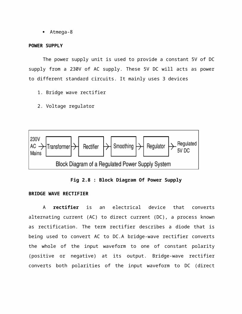
The power supply unit is used to provide a constant 5V of DC supply from a 230V of AC
supply. These 5V DC will acts as power to different standard circuits. It mainly uses 3 devices
1. Bridge wave rectifier
2. Voltage regulator

Fig 2.8 : Block Diagram Of Power Supply
BRIDGE WAVE RECTIFIER
A rectifier is an electrical device that converts alternating current (AC) to direct current
(DC), a process known as rectification. The term rectifier describes a diode that is being used to
convert AC to DC.A bridge-wave rectifier converts the whole of the input waveform to one of
constant polarity (positive or negative) at its output. Bridge-wave rectifier converts both polarities
of the input waveform to DC (direct current), and is more efficient. However, in a circuit with a
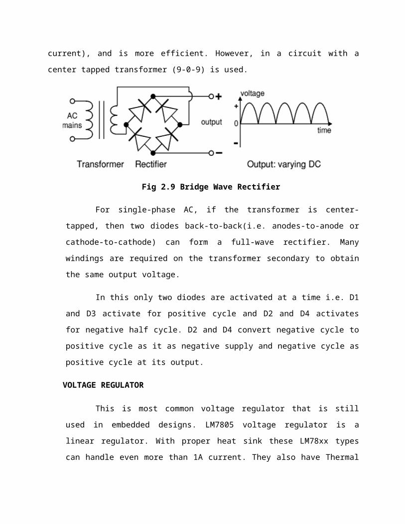
center tapped transformer (9-0-9) is used.
Fig 2.9 Bridge Wave Rectifier
For single-phase AC, if the transformer is center-tapped, then two diodes back-to-
back(i.e. anodes-to-anode or cathode-to-cathode) can form a full-wave rectifier. Many
windings are required on the transformer secondary to obtain the same output voltage.
In this only two diodes are activated at a time i.e. D1 and D3 activate for positive
cycle and D2 and D4 activates for negative half cycle. D2 and D4 convert negative cycle to
positive cycle as it as negative supply and negative cycle as positive cycle at its output.
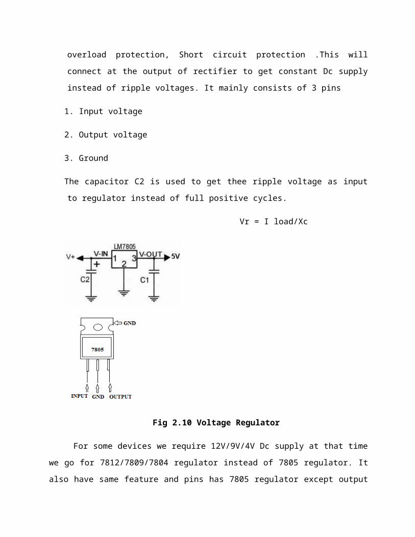
VOLTAGE REGULATOR
This is most common voltage regulator that is still used in embedded designs.
LM7805 voltage regulator is a linear regulator. With proper heat sink these LM78xx types
can handle even more than 1A current. They also have Thermal overload protection, Short
circuit protection .This will connect at the output of rectifier to get constant Dc supply
instead of ripple voltages. It mainly consists of 3 pins
1. Input voltage
2. Output voltage
3. Ground
The capacitor C2 is used to get thee ripple voltage as input to regulator instead of full
positive cycles.
Vr = I load/Xc
Fig 2.10 Voltage Regulator
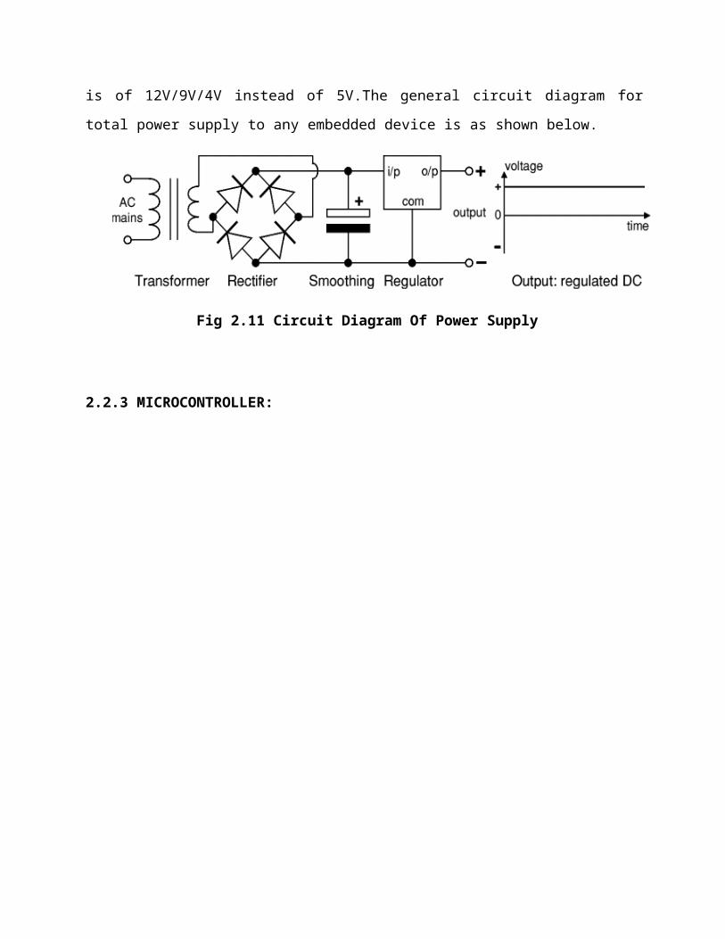
For some devices we require 12V/9V/4V Dc supply at that time we go for
7812/7809/7804 regulator instead of 7805 regulator. It also have same feature and pins has 7805
regulator except output is of 12V/9V/4V instead of 5V.The general circuit diagram for total
power supply to any embedded device is as shown below.
Fig 2.11 Circuit Diagram Of Power Supply

2.2.3 MICROCONTROLLER:
Fig 2.13 Show Pin Diagram of Atmega8l-PU
The Atmel®AVR® ATmega8 is a low-power CMOS 8-bit microcontroller based on the
AVR RISC architecture. By executing powerful instructions in a single clock cycle, the
ATmega8 achieves throughputs approaching 1MIPS per MHz, allowing the system designer to
optimize power consumption versus processing speed.
Features
High-performance, Low-power Atmel®AVR® 8-bit Microcontroller

Advanced RISC Architecture
130 Powerful Instructions – Most Single-clock Cycle Execution
32 × 8 General Purpose Working Registers
Up to 16MIPS Throughput at 16MHz
High Endurance Non-volatile Memory segments
8Kbytes of In-System Self-programmable Flash program memory
512Bytes EEPROM
1Kbyte Internal SRAM
Write/Erase Cycles: 10,000 Flash/100,000 EEPROM
Data retention: 20 years at 85°C/100 years at 25°C(1)
Programming Lock for Software Security
Peripheral Features
Two 8-bit Timer/Counters with Separate Prescaler, one Compare Mode
One 16-bit Timer/Counter with Separate Prescaler,Compare Mode, and Capture Mode
Real Time Counter with Separate Oscillator
Three PWM Channels.
6-channel ADC in PDIP package
Byte-oriented Two-wire Serial Interface
Programmable Serial USART
Master/Slave SPI Serial Interface
Programmable Watchdog Timer with Separate On-chip Oscillator
On-chip Analog Comparator
Special Microcontroller Features
Internal Calibrated RC Oscillator
External and Internal Interrupt Sources
Five Sleep Modes: Idle, ADC Noise Reduction, Power-save, Power-down, and
Standby
I/O and Packages
23 Programmable I/O Lines
28-lead PDIP.
Operating Voltages
2.7V - 5.5V (ATmega8L)
4.5V - 5.5V (ATmega8)
Speed Grades
0 - 8MHz (ATmega8L)
0 - 16MHz (ATmega8)
Power Consumption at 4 MHz, 3V, 25oC
Active: 3.6mA
Idle Mode: 1.0mA
Power-down Mode: 0.5μA
4 LCD 16x2
LCD screen is an electronic showcase and has broad variety of uses. These modules are superior more than 7 portions and added multi fragment LEDs. LCD is prudent.
Fig 3.10: LCD display 4bit mode Fig 3.11: pin functions of LCD
Easily programmable; have no detention of showing distinctive characters. A 16x2 LCD
surmises it can demonstrate 16 characters for each line. In this each character is in 5x7 pixel
frameworks. This LCD has 2 registers i.e., Cmd and Data.
The Cmd register stores guidelines that are given to LCD. The data register stores the
information that is visible on LCD.
3.2.5 Battery
Power bank are major source to run the prototype here 12volt 1.2ampere/hour sealed lead acid
battery is used to give constant supply for continuous operation of the system compared to
conventional lead acid battery this bank won’t spill and acid and no need to put distilled water an
additional charger need to charge the battery 14.1 volts is knows as battery full and 10 volts is
known as low battery discharging the battery beyond the level make the battery unusable.
Additional voltage reducer ic 7805 must be used to drive the digital part.
3.2.1 Ultrasonic Sensor
Ultrasonic sensors (generally called transceivers when they both send and get be that as it may
all the more generally called transducers) manage a rule like radar or sonar does the process for
a goal by deciphering the echoes from electromagnetic or sound waves solely. Ultrasonic sensors
make repeat sound waves and evaluate the resonation which is gotten back by the sensor.
Sensors figure the time break between sending the sign and tolerating the resonation to decide
the range of the target. Frameworks more often than not utilize a transducer which makes sound
waves in the ultrasonic degree, above 18,000 hertz, by changing electrical vitality into sound,
then in the wake of getting the reverberation change the sound waves into electrical centrality
which can be measured and showed up.
Figure 3. 6 Ultrasonic Sensor
Light Emitting Diodes (LEDs)
A light-emitting diode (LED) is a two-lead semiconductor light source. It is a p–n junction diode, which emits light when activated.[4]When a suitable voltage is applied to the leads, electrons are able to recombine with electron holes within the device, releasing energy in the form of photons. This effect is called electroluminescence, and the color of the light (corresponding to the energy of the photon) is determined by the energy band gap of the semiconductor.
An LED is often small in area (less than 1 mm2) and integrated optical components may be used to shape its radiation pattern.
Appearing as practical electronic components in 1962, [6] the earliest LEDs emitted low-intensity infrared light. Infrared LEDs are still frequently used as transmitting elements in remote-control circuits, such as those in remote controls for a wide variety of consumer electronics. The first visible-light LEDs were also of low intensity and limited to red. Modern LEDs are available across the visible, ultraviolet, and infrared wavelengths, with very high brightness.
Advantages
Internal defects can be detected and sized when a validated procedure is applied Thick specimens take no more time to examine than thin ones, assuming correct instrumentation
set up Access to only one side of the component is needed There is no radiation hazard in ultrasonic examination, and hence no disruption of work as there is
with radiography Volumetric and crack like defects can be detected, irrespective of their orientationDisadvantages
A high degree of operator skill and integrity is needed. Hence, the need for trained and certified NDT personnel
In most examinations, there is no permanent record of the inspection as there is in radiography, however more recent equipment does offer this facility
In certain materials, like austenitic steel, the large grain size found in welds can cause attenuation and this may mask defects
Spurious indications, and the misreading of signals, can result in unnecessary repairs, which is why a validated procedure should be applied when carrying out any ultrasonic examination.
Applications1.distance measurements over the objects.
2.speed of the approaching target.3.object detection over restricted area.4.enmies and unauthorized activity detections.
Results Once the hardware is designed, the Microcontroller was programmed to generate 40 kHz pulses. The receiver found responding to distances up to 10 meters and above in the initial stages. But this caused a problem of false triggering and inaccurate results. To avoid this, the range of the device has been greatly reduced by decreasing the amplifier gain and adjusting the variable resistance for range and sensitivity. Range finder encountered problem of false triggering, which was successfully eliminated by adjusting the locking frequency of Phase Locked Loop. Once this task is accomplished, software code is written for calculation of time of flight and distance measurement. The measured values are sent to PC through serial port using USART. Ultrasonic range finder found to be working efficiently, in the laboratory environment, where stray noises are less. However in open environment, it has produced less accurate results. Software algorithms can be employed to eliminate this problem in future. Ultrasonic range finder has successfully detected obstructions at a distance of 6 meters, while it produced accurate results when the obstruction is placed with in the range of 25 cm to 2 meters. With efficient algorithms, and filtering techniques, measurement range can be improved to a greater extent.
CONCLUSION The paper presents a low-cost, low power and simple system for distance measurement. The precision of the result high compared to other conventional methods. Fig. 4 shows the model of this paper implemented. It is certainly a reliable and efficient method for instantaneous measurement of distance. Since the system remained unaffected with the human activity. This system will have high application in civil and mechanical field of engineering [9] [10] where it has been a bigger challenge for precise measurement of small and physically unreachable distances. It will surely have influence on small and large technicians who find measurements challenging in different severe environments. The future modification may include addition of speaker for distance announcement, portable device etc.


![Ultrasonic Based Distance Measurement System - News · PDF fileEE616 Electronic Design Lab Project Report, ... [2] K. J. Ayala, 8051 Microcontroller, ... GAIN AMPLIFIER ULTRASONIC](https://static.fdocuments.in/doc/165x107/5a700db87f8b9abb538b95a5/ultrasonic-based-distance-measurement-system-newswww8051projectsnetfilespublic133794617138097ft0reportpdfpdf.jpg)