
TWIN-TURBINE CENTRIFUGAL COMPRESSOR - … Monitoring Tools Quick Start... · TWIN-TURBINE...
29
SERVICE MONITORING TOOLS QUICK START GUIDE M-SM-002-EN Rev. C October 2013 TWIN-TURBINE CENTRIFUGAL COMPRESSOR
Transcript of TWIN-TURBINE CENTRIFUGAL COMPRESSOR - … Monitoring Tools Quick Start... · TWIN-TURBINE...

TWIN-TURBINE CENTRIFUGAL COMPRESSOR
SERVICE MONITORING TOOLS QUICK START GUIDEM-SM-002-EN Rev. C
October 2013

This Page Left Intentionally Blank
Table of Contents
Danfoss Turbocor Compressors Inc. 3M-SM-002-EN Rev. C
Service Monitoring Tools Quick Start Guide
1 Service Monitoring Tools Quick Start ...................................................................................................... 41.1 Compatibility Requirements..................................................................................................... 41.2 Installing the Service Monitoring Tools .................................................................................... 41.3 Starting the SMT Software..................................................................................................... 101.4 Connecting to a Compressor ................................................................................................. 11
1.4.1 Shared Connection .................................................................................................131.4.2 Direct Connection ...................................................................................................151.4.3 TCP/IP Connection .................................................................................................17
1.5 Running a Simulation............................................................................................................. 181.6 SMT Suite Launcher Strip Tool Options ................................................................................ 24
1.6.1 Right-Click Context Menu .......................................................................................261.7 General Usage....................................................................................................................... 26
1.7.1 Internal Logging System .........................................................................................261.7.2 Informative Tooltips ................................................................................................261.7.3 Highlight-on-click ....................................................................................................261.7.4 Collapsible Group Boxes ........................................................................................271.7.5 Interactive Graphs ..................................................................................................271.7.6 Persistent User Settings .........................................................................................281.7.7 The Remote Serial Multiplexer ...............................................................................281.7.8 Normalized Tool Framework...................................................................................281.7.9 Product Update Checking.......................................................................................281.7.10 Tool Identification..................................................................................................29
Service Monitoring Tools Quick Start Guide
1 Service Monitoring Tools Quick Start
1.1 Compatibility Requirements
The Service Monitoring Tools software system requires the following environment for operation:
• Framework: .NET Framework Version 3.5 or later
• Operating System: Microsoft Windows XP (32-bit or 64-bit) SP2 or later, Microsoft Windows Vista (32-bit or 64-bit) Basic or better, or Microsoft Windows 7 (32-bit or 64-bit) Home Basic or better
• Hardware: 1.0 GHz or higher CPU, minimum OS-required RAM, 1024x768 high-color display (or better), and 20 MB or more available hard-disk space
1.2 Installing the Service Monitoring Tools
To install the Service Monitoring Tools.
1. Download the smt3ginstall.exe file to your computer.
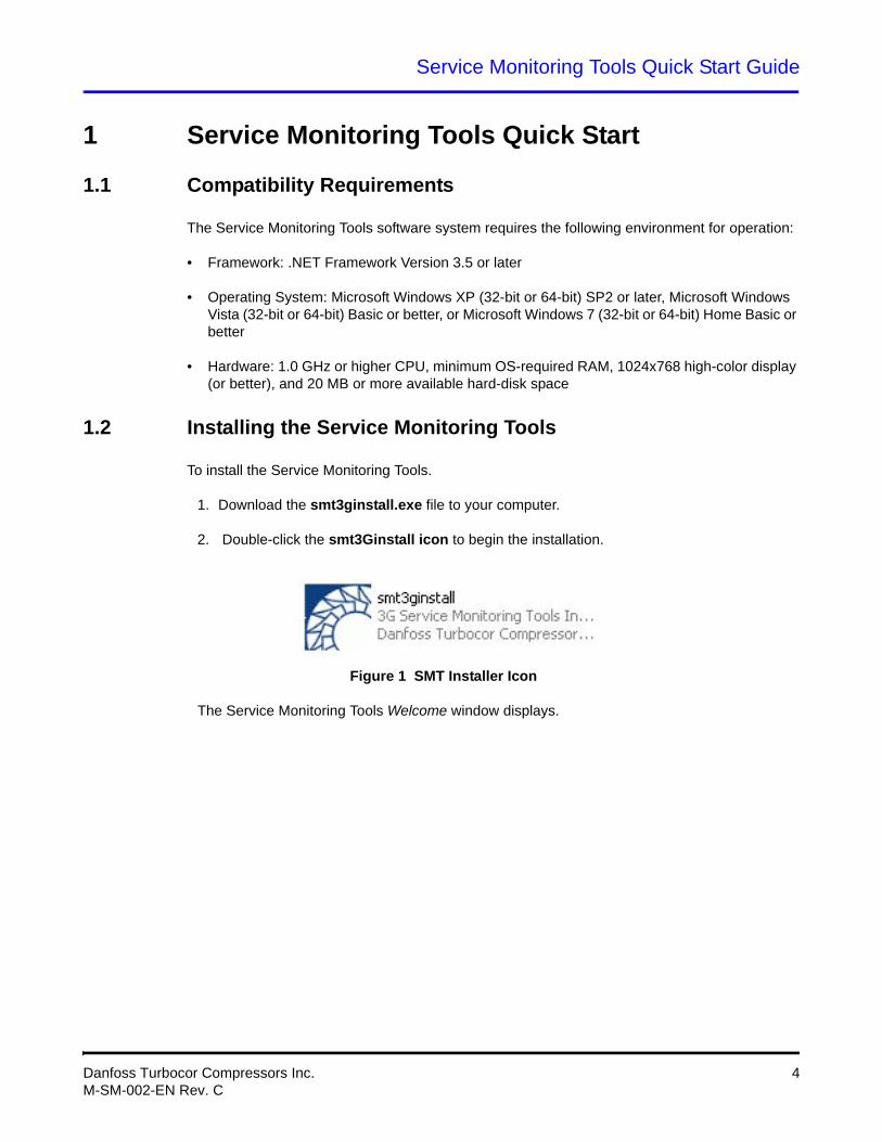
2. Double-click the smt3Ginstall icon to begin the installation.
Figure 1 SMT Installer Icon
The Service Monitoring Tools Welcome window displays.
Danfoss Turbocor Compressors Inc. 4M-SM-002-EN Rev. C
Service Monitoring Tools Quick Start Guide
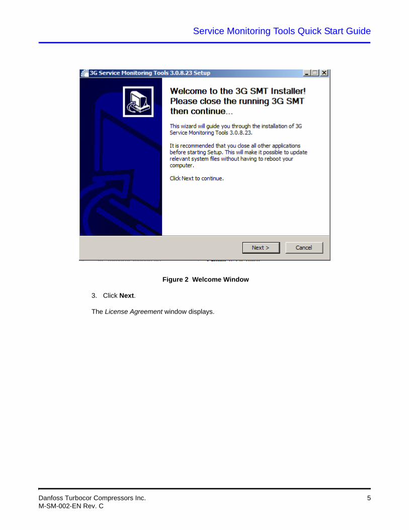
Figure 2 Welcome Window
3. Click Next.
The License Agreement window displays.
Danfoss Turbocor Compressors Inc. 5M-SM-002-EN Rev. C
Service Monitoring Tools Quick Start Guide
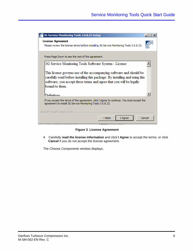
Figure 3 License Agreement
4. Carefully read the license information and click I Agree to accept the terms, or click Cancel if you do not accept the license agreement.
The Choose Components window displays.
Danfoss Turbocor Compressors Inc. 6M-SM-002-EN Rev. C
Service Monitoring Tools Quick Start Guide
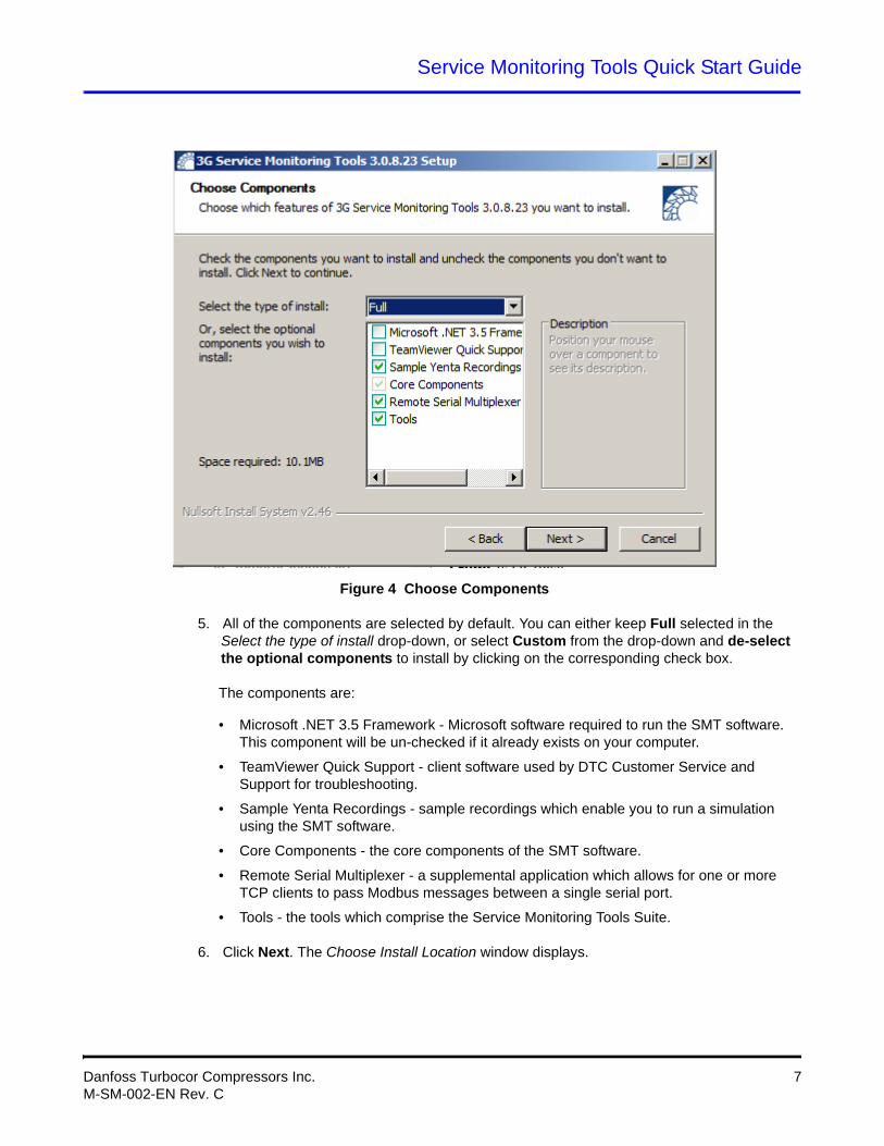
Figure 4 Choose Components
5. All of the components are selected by default. You can either keep Full selected in the Select the type of install drop-down, or select Custom from the drop-down and de-select the optional components to install by clicking on the corresponding check box.
The components are:
• Microsoft .NET 3.5 Framework - Microsoft software required to run the SMT software. This component will be un-checked if it already exists on your computer.
• TeamViewer Quick Support - client software used by DTC Customer Service and Support for troubleshooting.
• Sample Yenta Recordings - sample recordings which enable you to run a simulation using the SMT software.
• Core Components - the core components of the SMT software.
• Remote Serial Multiplexer - a supplemental application which allows for one or more TCP clients to pass Modbus messages between a single serial port.
• Tools - the tools which comprise the Service Monitoring Tools Suite.
6. Click Next. The Choose Install Location window displays.
Danfoss Turbocor Compressors Inc. 7M-SM-002-EN Rev. C
Service Monitoring Tools Quick Start Guide
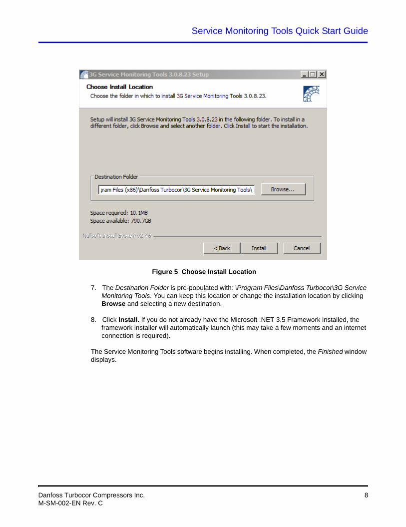
Figure 5 Choose Install Location
7. The Destination Folder is pre-populated with: \Program Files\Danfoss Turbocor\3G Service Monitoring Tools. You can keep this location or change the installation location by clicking Browse and selecting a new destination.
8. Click Install. If you do not already have the Microsoft .NET 3.5 Framework installed, the framework installer will automatically launch (this may take a few moments and an internet connection is required).
The Service Monitoring Tools software begins installing. When completed, the Finished window displays.
Danfoss Turbocor Compressors Inc. 8M-SM-002-EN Rev. C
Service Monitoring Tools Quick Start Guide
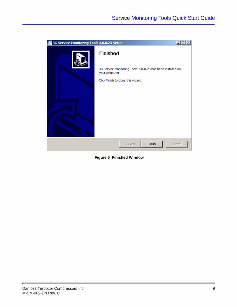
Figure 6 Finished Window
Danfoss Turbocor Compressors Inc. 9M-SM-002-EN Rev. C
Service Monitoring Tools Quick Start Guide
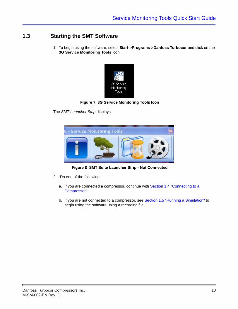
1.3 Starting the SMT Software
1. To begin using the software, select Start->Programs->Danfoss Turbocor and click on the 3G Service Monitoring Tools icon.
Figure 7 3G Service Monitoring Tools Icon
The SMT Launcher Strip displays.
Figure 8 SMT Suite Launcher Strip - Not Connected
2. Do one of the following:
a. If you are connected a compressor, continue with Section 1.4 "Connecting to a Compressor".
b. If you are not connected to a compressor, see Section 1.5 "Running a Simulation" to begin using the software using a recording file.
Danfoss Turbocor Compressors Inc. 10M-SM-002-EN Rev. C
Service Monitoring Tools Quick Start Guide
1.4 Connecting to a Compressor
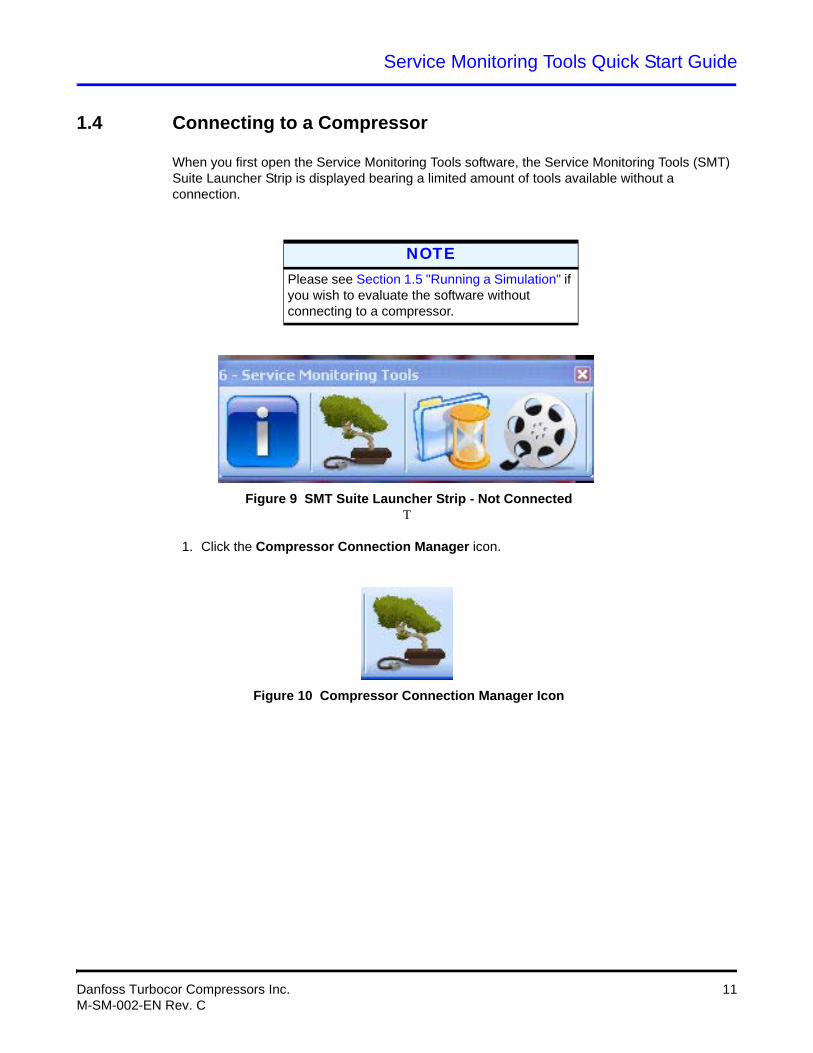
When you first open the Service Monitoring Tools software, the Service Monitoring Tools (SMT) Suite Launcher Strip is displayed bearing a limited amount of tools available without a connection.
Figure 9 SMT Suite Launcher Strip - Not ConnectedT
1. Click the Compressor Connection Manager icon.
Figure 10 Compressor Connection Manager Icon
NOTEPlease see Section 1.5 "Running a Simulation" if you wish to evaluate the software without connecting to a compressor.
Danfoss Turbocor Compressors Inc. 11M-SM-002-EN Rev. C
Service Monitoring Tools Quick Start Guide
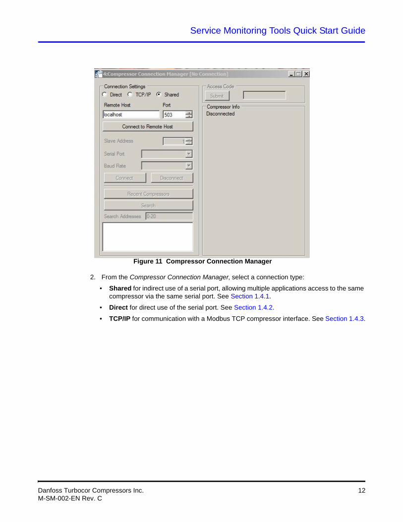
Figure 11 Compressor Connection Manager
2. From the Compressor Connection Manager, select a connection type:
• Shared for indirect use of a serial port, allowing multiple applications access to the same compressor via the same serial port. See Section 1.4.1.
• Direct for direct use of the serial port. See Section 1.4.2.
• TCP/IP for communication with a Modbus TCP compressor interface. See Section 1.4.3.
Danfoss Turbocor Compressors Inc. 12M-SM-002-EN Rev. C
Service Monitoring Tools Quick Start Guide
1.4.1 Shared Connection
1. Once you have selected Shared as your connection type, enter your shared host name and TCP port number. The default values are usually fine.
2. Click the Connect to Remote Host button.
3. Select a Serial Port Name. The items listed in the drop-down labeled Serial Port identify available compressor data streams - typically, the default (and most likely only) selection is sufficient.
4. If the slave address and baud rate are known, follow steps a and b below; otherwise proceed to step 5.
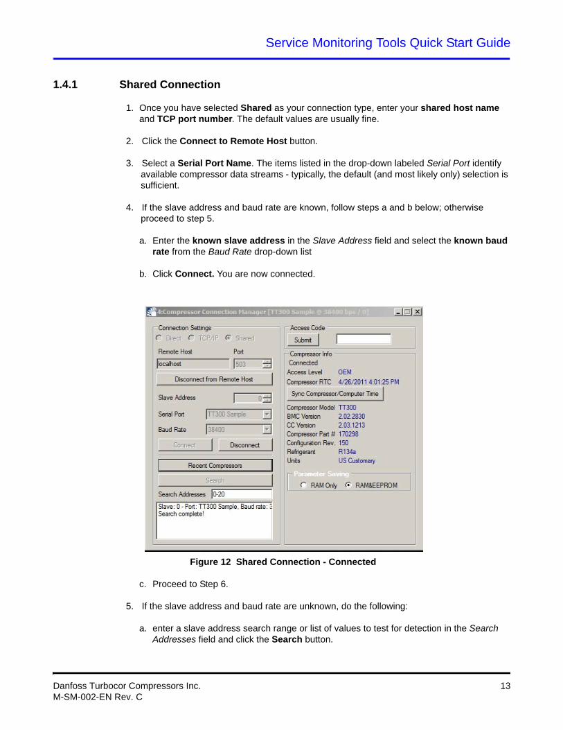
a. Enter the known slave address in the Slave Address field and select the known baud rate from the Baud Rate drop-down list
b. Click Connect. You are now connected.
Figure 12 Shared Connection - Connected
c. Proceed to Step 6.
5. If the slave address and baud rate are unknown, do the following:
a. enter a slave address search range or list of values to test for detection in the Search Addresses field and click the Search button.
Danfoss Turbocor Compressors Inc. 13M-SM-002-EN Rev. C
Service Monitoring Tools Quick Start Guide
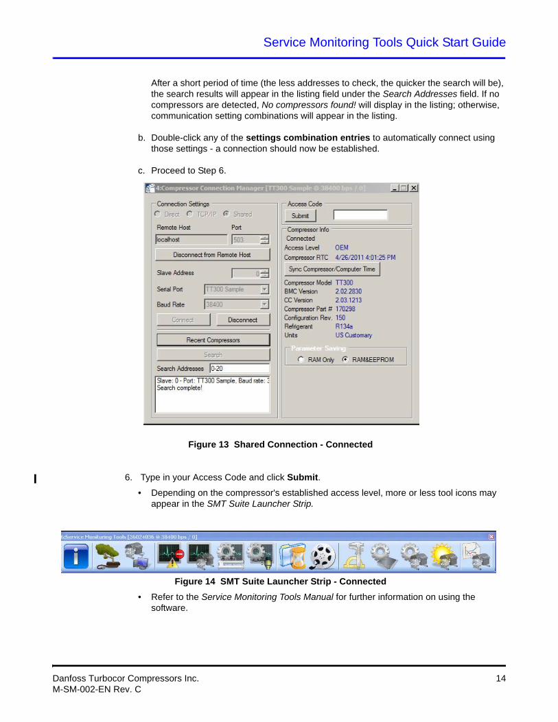
After a short period of time (the less addresses to check, the quicker the search will be), the search results will appear in the listing field under the Search Addresses field. If no compressors are detected, No compressors found! will display in the listing; otherwise, communication setting combinations will appear in the listing.
b. Double-click any of the settings combination entries to automatically connect using those settings - a connection should now be established.
c. Proceed to Step 6.
Figure 13 Shared Connection - Connected
6. Type in your Access Code and click Submit.
• Depending on the compressor's established access level, more or less tool icons may appear in the SMT Suite Launcher Strip.
Figure 14 SMT Suite Launcher Strip - Connected
• Refer to the Service Monitoring Tools Manual for further information on using the software.
Danfoss Turbocor Compressors Inc. 14M-SM-002-EN Rev. C
Service Monitoring Tools Quick Start Guide
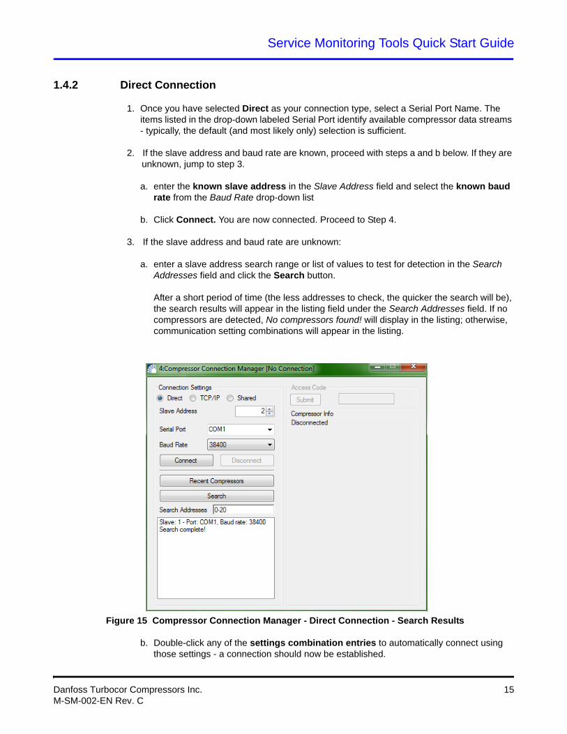
1.4.2 Direct Connection
1. Once you have selected Direct as your connection type, select a Serial Port Name. The items listed in the drop-down labeled Serial Port identify available compressor data streams - typically, the default (and most likely only) selection is sufficient.
2. If the slave address and baud rate are known, proceed with steps a and b below. If they are unknown, jump to step 3.
a. enter the known slave address in the Slave Address field and select the known baud rate from the Baud Rate drop-down list
b. Click Connect. You are now connected. Proceed to Step 4.
3. If the slave address and baud rate are unknown:
a. enter a slave address search range or list of values to test for detection in the Search Addresses field and click the Search button.
After a short period of time (the less addresses to check, the quicker the search will be), the search results will appear in the listing field under the Search Addresses field. If no compressors are detected, No compressors found! will display in the listing; otherwise, communication setting combinations will appear in the listing.
Figure 15 Compressor Connection Manager - Direct Connection - Search Results
b. Double-click any of the settings combination entries to automatically connect using those settings - a connection should now be established.
Danfoss Turbocor Compressors Inc. 15M-SM-002-EN Rev. C
Service Monitoring Tools Quick Start Guide
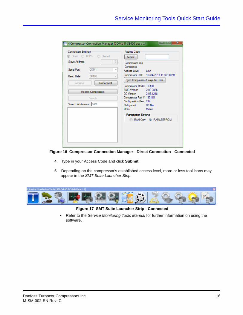
Figure 16 Compressor Connection Manager - Direct Connection - Connected
4. Type in your Access Code and click Submit.
5. Depending on the compressor's established access level, more or less tool icons may appear in the SMT Suite Launcher Strip.
Figure 17 SMT Suite Launcher Strip - Connected
• Refer to the Service Monitoring Tools Manual for further information on using the software.
Danfoss Turbocor Compressors Inc. 16M-SM-002-EN Rev. C
Service Monitoring Tools Quick Start Guide
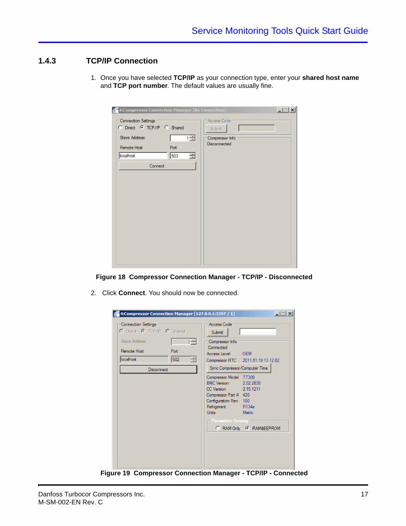
1.4.3 TCP/IP Connection
1. Once you have selected TCP/IP as your connection type, enter your shared host name and TCP port number. The default values are usually fine.
Figure 18 Compressor Connection Manager - TCP/IP - Disconnected
2. Click Connect. You should now be connected.
Figure 19 Compressor Connection Manager - TCP/IP - Connected
Danfoss Turbocor Compressors Inc. 17M-SM-002-EN Rev. C
Service Monitoring Tools Quick Start Guide
3. Type in your Access Code and click Submit.
4. Depending on the compressor's established access level, more or less tool icons may appear in the SMT Suite Launcher Strip.
Figure 20 SMT Suite Launcher Strip - Connected
• Refer to the Service Monitoring Tools Manual for further information on using the software.
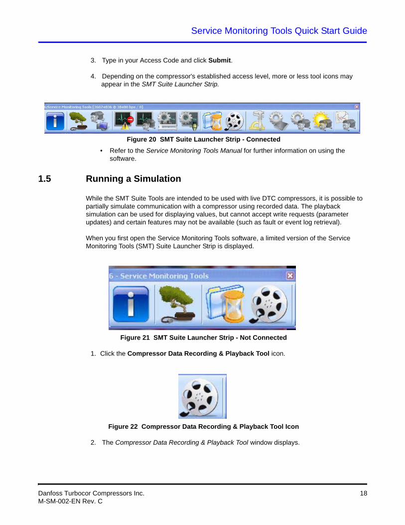
1.5 Running a Simulation
While the SMT Suite Tools are intended to be used with live DTC compressors, it is possible to partially simulate communication with a compressor using recorded data. The playback simulation can be used for displaying values, but cannot accept write requests (parameter updates) and certain features may not be available (such as fault or event log retrieval).
When you first open the Service Monitoring Tools software, a limited version of the Service Monitoring Tools (SMT) Suite Launcher Strip is displayed.
Figure 21 SMT Suite Launcher Strip - Not Connected
1. Click the Compressor Data Recording & Playback Tool icon.
Figure 22 Compressor Data Recording & Playback Tool Icon
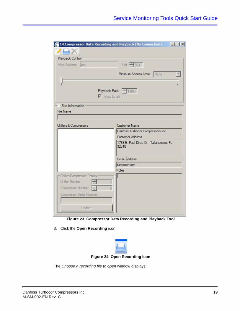
2. The Compressor Data Recording & Playback Tool window displays.
Danfoss Turbocor Compressors Inc. 18M-SM-002-EN Rev. C
Service Monitoring Tools Quick Start Guide
Figure 23 Compressor Data Recording and Playback Tool
3. Click the Open Recording icon.
Figure 24 Open Recording Icon
The Choose a recording file to open window displays:
Danfoss Turbocor Compressors Inc. 19M-SM-002-EN Rev. C
Service Monitoring Tools Quick Start Guide
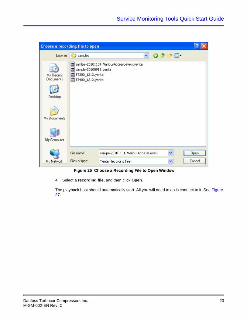
Figure 25 Choose a Recording File to Open Window
4. Select a recording file, and then click Open.
The playback host should automatically start. All you will need to do is connect to it. See Figure 27.
Danfoss Turbocor Compressors Inc. 20M-SM-002-EN Rev. C
Service Monitoring Tools Quick Start Guide
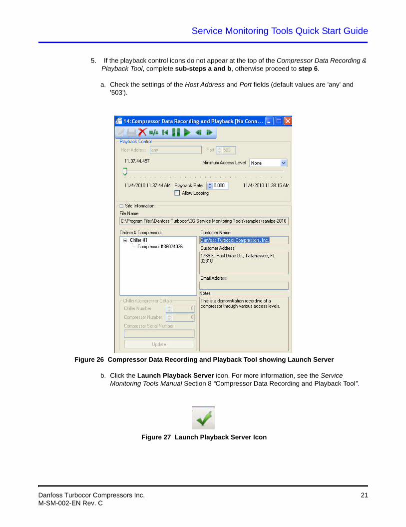
5. If the playback control icons do not appear at the top of the Compressor Data Recording & Playback Tool, complete sub-steps a and b, otherwise proceed to step 6.
a. Check the settings of the Host Address and Port fields (default values are 'any' and '503').
Figure 26 Compressor Data Recording and Playback Tool showing Launch Server
b. Click the Launch Playback Server icon. For more information, see the Service Monitoring Tools Manual Section 8 “Compressor Data Recording and Playback Tool”.
Figure 27 Launch Playback Server Icon
Danfoss Turbocor Compressors Inc. 21M-SM-002-EN Rev. C
Service Monitoring Tools Quick Start Guide
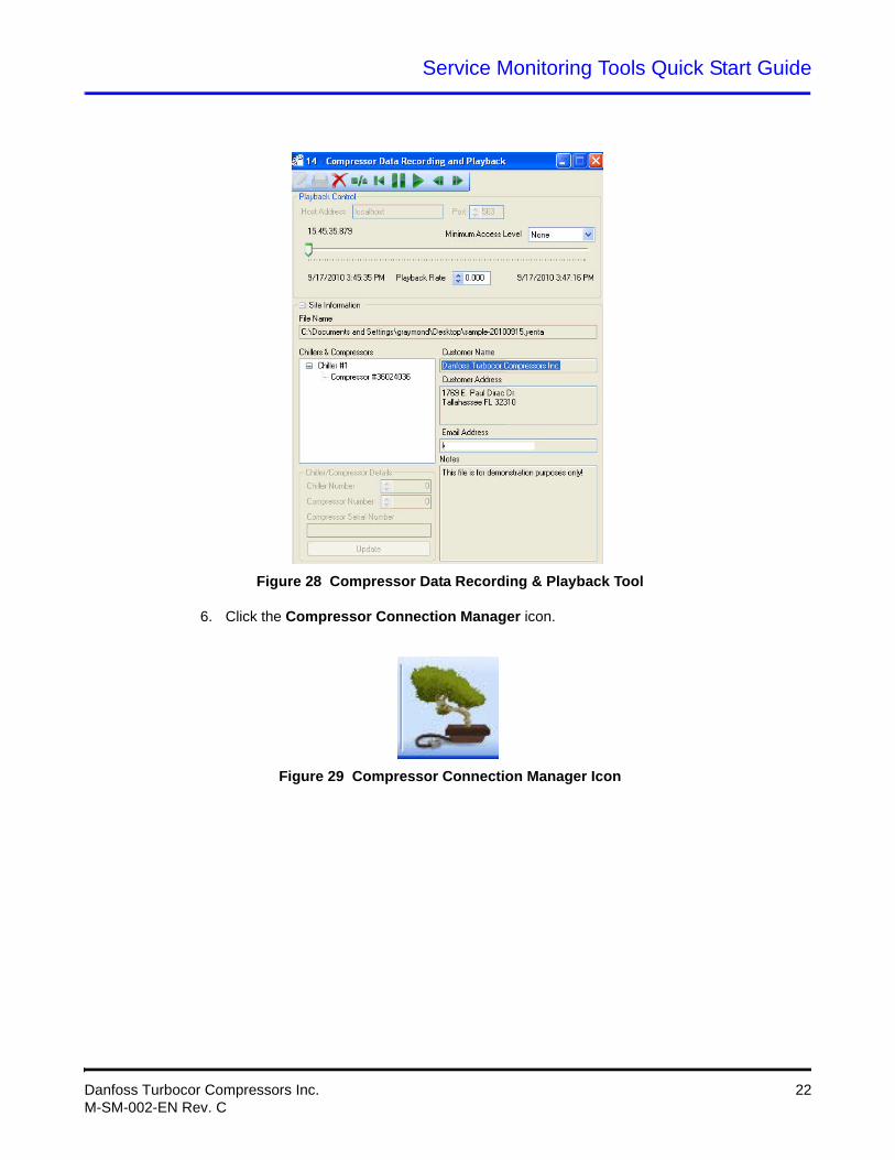
Figure 28 Compressor Data Recording & Playback Tool
6. Click the Compressor Connection Manager icon.
Figure 29 Compressor Connection Manager Icon
Danfoss Turbocor Compressors Inc. 22M-SM-002-EN Rev. C
Service Monitoring Tools Quick Start Guide
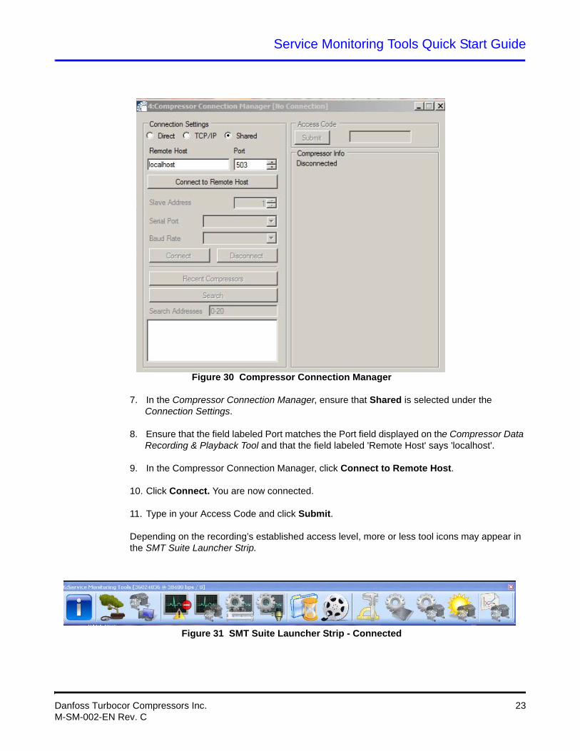
Figure 30 Compressor Connection Manager
7. In the Compressor Connection Manager, ensure that Shared is selected under the Connection Settings.
8. Ensure that the field labeled Port matches the Port field displayed on the Compressor Data Recording & Playback Tool and that the field labeled 'Remote Host' says 'localhost'.
9. In the Compressor Connection Manager, click Connect to Remote Host.
10. Click Connect. You are now connected.
11. Type in your Access Code and click Submit.
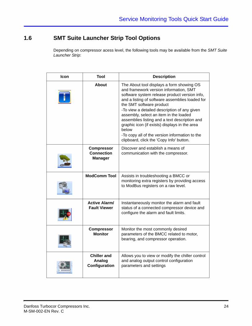
Depending on the recording’s established access level, more or less tool icons may appear in the SMT Suite Launcher Strip.
Figure 31 SMT Suite Launcher Strip - Connected
Danfoss Turbocor Compressors Inc. 23M-SM-002-EN Rev. C
Service Monitoring Tools Quick Start Guide
1.6 SMT Suite Launcher Strip Tool Options
Depending on compressor acess level, the following tools may be available from the SMT Suite Launcher Strip:
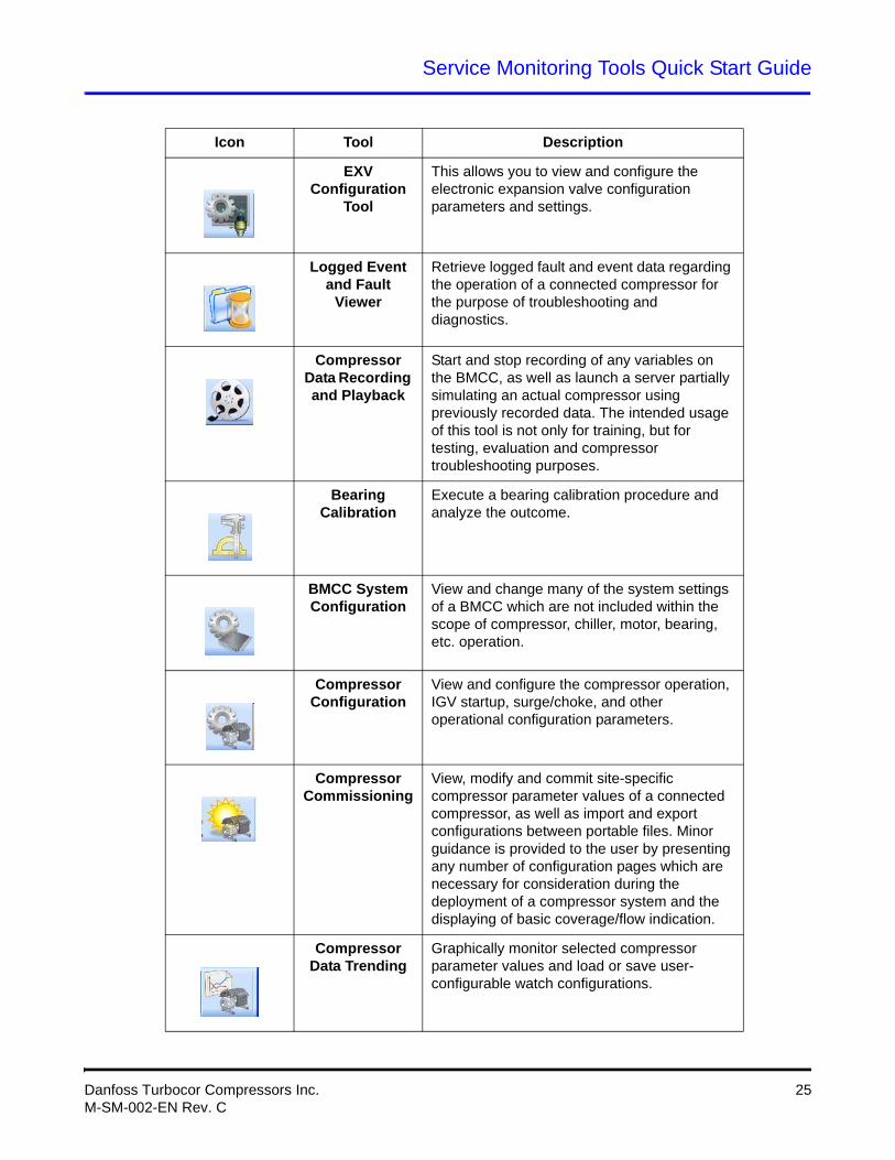
Icon Tool Description
About The About tool displays a form showing OS and framework version information, SMT software system release product version info, and a listing of software assemblies loaded for the SMT software product-To view a detailed description of any given assembly, select an item in the loaded assemblies listing and a text description and graphic icon (if exists) displays in the area below-To copy all of the version information to the clipboard, click the 'Copy Info' button.
Compressor Connection
Manager
Discover and establish a means of communication with the compressor.
ModComm Tool Assists in troubleshooting a BMCC or monitoring extra registers by providing access to ModBus registers on a raw level.
Active Alarm/Fault Viewer
Instantaneously monitor the alarm and fault status of a connected compressor device and configure the alarm and fault limits.
Compressor Monitor
Monitor the most commonly desired parameters of the BMCC related to motor, bearing, and compressor operation.
Chiller and Analog
Configuration
Allows you to view or modify the chiller control and analog output control configuration parameters and settings
Danfoss Turbocor Compressors Inc. 24M-SM-002-EN Rev. C
Service Monitoring Tools Quick Start Guide
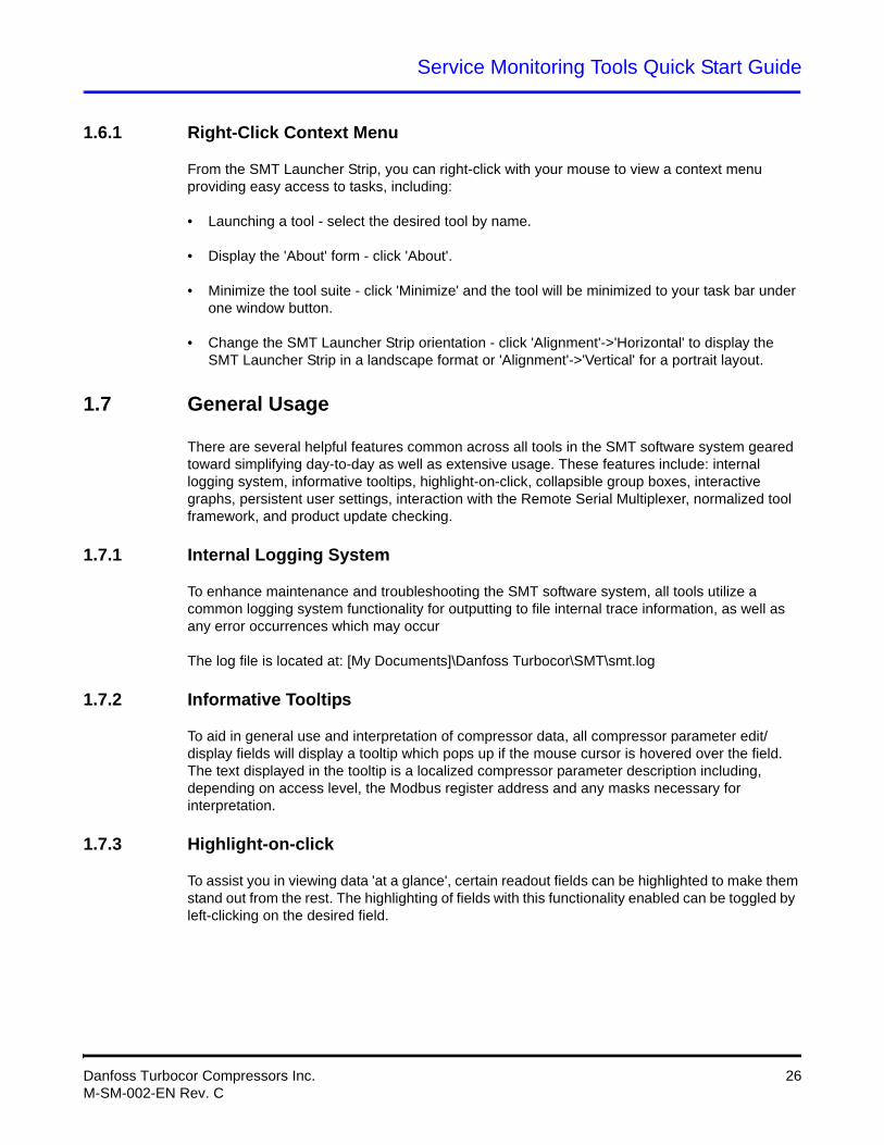
EXV Configuration
Tool
This allows you to view and configure the electronic expansion valve configuration parameters and settings.
Logged Event and Fault
Viewer
Retrieve logged fault and event data regarding the operation of a connected compressor for the purpose of troubleshooting and diagnostics.
Compressor Data Recording and Playback
Start and stop recording of any variables on the BMCC, as well as launch a server partially simulating an actual compressor using previously recorded data. The intended usage of this tool is not only for training, but for testing, evaluation and compressor troubleshooting purposes.
Bearing Calibration
Execute a bearing calibration procedure and analyze the outcome.
BMCC System Configuration
View and change many of the system settings of a BMCC which are not included within the scope of compressor, chiller, motor, bearing, etc. operation.
Compressor Configuration
View and configure the compressor operation, IGV startup, surge/choke, and other operational configuration parameters.
Compressor Commissioning
View, modify and commit site-specific compressor parameter values of a connected compressor, as well as import and export configurations between portable files. Minor guidance is provided to the user by presenting any number of configuration pages which are necessary for consideration during the deployment of a compressor system and the displaying of basic coverage/flow indication.
Compressor Data Trending
Graphically monitor selected compressor parameter values and load or save user-configurable watch configurations.
Icon Tool Description
Danfoss Turbocor Compressors Inc. 25M-SM-002-EN Rev. C
Service Monitoring Tools Quick Start Guide
1.6.1 Right-Click Context Menu
From the SMT Launcher Strip, you can right-click with your mouse to view a context menu providing easy access to tasks, including:
• Launching a tool - select the desired tool by name.
• Display the 'About' form - click 'About'.
• Minimize the tool suite - click 'Minimize' and the tool will be minimized to your task bar under one window button.
• Change the SMT Launcher Strip orientation - click 'Alignment'->'Horizontal' to display the SMT Launcher Strip in a landscape format or 'Alignment'->'Vertical' for a portrait layout.
1.7 General Usage
There are several helpful features common across all tools in the SMT software system geared toward simplifying day-to-day as well as extensive usage. These features include: internal logging system, informative tooltips, highlight-on-click, collapsible group boxes, interactive graphs, persistent user settings, interaction with the Remote Serial Multiplexer, normalized tool framework, and product update checking.
1.7.1 Internal Logging System
To enhance maintenance and troubleshooting the SMT software system, all tools utilize a common logging system functionality for outputting to file internal trace information, as well as any error occurrences which may occur
The log file is located at: [My Documents]\Danfoss Turbocor\SMT\smt.log
1.7.2 Informative Tooltips
To aid in general use and interpretation of compressor data, all compressor parameter edit/display fields will display a tooltip which pops up if the mouse cursor is hovered over the field. The text displayed in the tooltip is a localized compressor parameter description including, depending on access level, the Modbus register address and any masks necessary for interpretation.
1.7.3 Highlight-on-click
To assist you in viewing data 'at a glance', certain readout fields can be highlighted to make them stand out from the rest. The highlighting of fields with this functionality enabled can be toggled by left-clicking on the desired field.
Danfoss Turbocor Compressors Inc. 26M-SM-002-EN Rev. C
Service Monitoring Tools Quick Start Guide
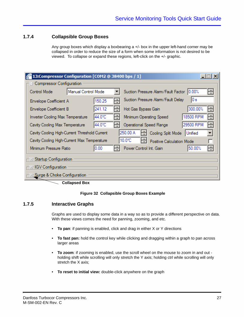
1.7.4 Collapsible Group Boxes
Any group boxes which display a boxbearing a +/- box in the upper left-hand corner may be collapsed in order to reduce the size of a form when some information is not desired to be viewed. To collapse or expand these regions, left-click on the +/- graphic.
Figure 32 Collapsible Group Boxes Example
1.7.5 Interactive Graphs
Graphs are used to display some data in a way so as to provide a different perspective on data. With these views comes the need for panning, zooming, and etc.
• To pan: if panning is enabled, click and drag in either X or Y directions
• To fast pan: hold the control key while clicking and dragging within a graph to pan across larger areas
• To zoom: if zooming is enabled, use the scroll wheel on the mouse to zoom in and out - holding shift while scrolling will only stretch the Y axis; holding ctrl while scrolling will only stretch the X axis;
• To reset to initial view: double-click anywhere on the graph
Collapsed Box
Danfoss Turbocor Compressors Inc. 27M-SM-002-EN Rev. C
Service Monitoring Tools Quick Start Guide
1.7.6 Persistent User Settings
Many of the interface settings are saved in a local settings file in order to persist common settings on a user-by-user basis.
Typical persistent settings include: tool form screen location, tool form normal/maximized state, collapsible form collapse/expand states, user-entered application fields (i.e. hostnames, TCP ports, technician name fields, etc.).
The settings file is located at: [My Documents]\Danfoss Turbocor\SMT\Settings.xml
1.7.7 The Remote Serial Multiplexer
An additional component developed for use with many other software systems in mind, but particularly the SMT is the Remote Serial Multiplexer. The Remote Serial Multiplexer is a system which allows multiple applications to indirectly communicate with a single device connected to one serial port. In addition to local serial port multiplexing, this system can be used remotely. For example, machine A, which is connected to a compressor, may allow machine B to communicate with its compressor, although machine B is in a different building, so long as there is a network/Internet connection enabling communication between the two computers.
1.7.8 Normalized Tool Framework
All components considered to be tools contain a commonly-structured data identifying a tool and its interface components.
Data included in the tool metadata (assembly information) include: Tool Id #, Tool Name Id, Tool Description Id, Tool Classification, Minimum (execution) Access Level, Enumeration Count, Persistence, Connection Requirement, Dedication Requirement, and an Application Graphic.
In addition to the framework metadata, there are several components geared toward the utilization of these tool components, including standalone execution support, common interfacing components, etc.
1.7.9 Product Update Checking
To keep users informed of available updates, an automatic update check and notification can be enabled, which will indicate to the user if there is a newer version of the SMT software product available for download.
This process is performed by downloading the latest product information from a Turbocor website and comparing the indicated version against the current product version. To prevent possibly malicious modification of the product release notice, authentication can be performed by checking a required signature of the product info message using the assembly's public key, which is part of the same key pair used for signing the product release notice.
Danfoss Turbocor Compressors Inc. 28M-SM-002-EN Rev. C
Service Monitoring Tools Quick Start Guide
1.7.10 Tool Identification
Each tool's title frame contains information identifying it. This information includes:
• Tool/Form ID - The first number, indicating the ID number of the current tool
• Tool Title - The localized text title of the current tool
• Device Connection Info - This includes the serial port and baud rate or IP address and port number and the slave address of the device with which the current tool is connected.
• Refer to the Service Monitoring Tools Manual for further information on using the software.
NOTETo differentiate between instances of the SMT, look at the device communication information displayed in the tool’s frame.
Danfoss Turbocor Compressors Inc. 29M-SM-002-EN Rev. C