Real Estate Advertiser - Niagara Region - September 11, 2014

The Niagara Region Traffic Signal Standards January 2014

Identification No. The Niagara Region Traffic Signal Standards This document belongs to:

TABLE OF CONTENTS
1.0 INTRODUCTION .......................................................................................................................................... 1
1.1 MANUAL LAYOUT ......................................................................................................................................... 1 1.2 TERMINOLOGY .............................................................................................................................................. 3 1.3 ADDITIONAL REFERENCES ............................................................................................................................ 3 1.4 REGIONAL OPERATING STRUCTURE .............................................................................................................. 4
2.0 NIAGARA REGION DESIGN PROCESS .................................................................................................. 5
2.1 DESIGN INITIATION ....................................................................................................................................... 6 2.2 PRELIMINARY TRAFFIC SIGNAL DESIGN ....................................................................................................... 6 2.3 FINAL TRAFFIC SIGNAL DESIGN ................................................................................................................... 7 2.4 TRAFFIC SIGNAL CONSTRUCTION ................................................................................................................. 7 TABLE 2.1 – TRAFFIC SIGNAL DESIGN PROCESS ........................................................................................... 8 TABLE 2.1 – TRAFFIC SIGNAL DESIGN PROCESS CONTINUED .................................................................... 9
3.0 NIAGARA REGION OPERATING PRACTICES ................................................................................... 11
3.1 CONTROL METHODOLOGIES ....................................................................................................................... 11 3.2 SIGNAL PHASING ........................................................................................................................................ 13 3.3 VEHICLE DETECTION .................................................................................................................................. 13 3.4 SIGNAL TIMING PARAMETERS .................................................................................................................... 14
4.0 NIAGARA REGION DESIGN PRACTICES ............................................................................................ 17
4.1 SIGNAL HEAD VISIBILITY AND PLACEMENT ............................................................................................... 17 4.2 SIGNAL POLE PLACEMENT .......................................................................................................................... 23 4.3 PLACEMENT OF TRAFFIC SIGNAL CONTROLLER CABINETS ......................................................................... 26 4.4 VEHICLE AND PEDESTRIAN DETECTION ...................................................................................................... 27 4.5 JUNCTION BOXES/HANDHOLES AND TRAFFIC DUCTS ................................................................................. 28 4.6 GROUNDING REQUIREMENTS ...................................................................................................................... 29 4.7 TYPICAL DESIGN LAYOUTS......................................................................................................................... 29
5.0 REGIONAL DESIGN AND CONSTRUCTION SPECIFICATIONS .................................................... 30
5.1 REGIONALLY APPROVED MATERIALS LISTING ........................................................................................... 30 5.2 GENERAL CONDITIONS ............................................................................................................................... 30 5.3 ABOVE GROUND TRAFFIC SIGNAL WORKS ................................................................................................. 31
5.3.1 Traffic Signal Heads .............................................................................................................................. 32 5.3.2 Traffic Signal Arms ................................................................................................................................ 32 5.3.3 Traffic Signal Poles ............................................................................................................................... 33 5.3.4 Pedestrian Push Buttons and Signs ....................................................................................................... 33 5.3.5 Traffic Signal Cable and Wiring ............................................................................................................ 34 5.3.6 Vehicle Detection ................................................................................................................................... 34 5.3.7 Power Feed and Disconnect .................................................................................................................. 35 5.3.8 Intersection Illumination and Wiring ...................................................................................................... 35 5.3.9 Traffic Signal Control Cabinet ............................................................................................................... 35
5.4 UNDERGROUND TRAFFIC SIGNAL WORKS .................................................................................................. 36 5.4.1 Concrete Pole Bases .............................................................................................................................. 36 5.4.2 Concrete Controller Bases ..................................................................................................................... 36 5.4.3 Traffic Ducts .......................................................................................................................................... 36 5.4.4 Junction Boxes ....................................................................................................................................... 37
6.0 ENGINEERING SUBMISSION REQUIREMENTS ................................................................................ 38
6.1 GENERAL .................................................................................................................................................... 38 6.2 LETTER OF TRANSMITTAL ........................................................................................................................... 38 6.3 ENGINEERING DESIGN BRIEF ...................................................................................................................... 38

6.4 DRAWINGS .................................................................................................................................................. 38 6.4.1 Electronic File ....................................................................................................................................... 38 6.4.2 Hardcopy ............................................................................................................................................... 39
6.5 CONTRACT DRAWINGS ............................................................................................................................... 39 6.5.1 Title Sheet .............................................................................................................................................. 39 6.5.2 Traffic Signal Construction Drawing .................................................................................................... 40 6.5.3 Wiring Diagram Detail .......................................................................................................................... 40 6.5.4 Electrical Detail Drawings (Non Standard if required) ........................................................................ 40
6.6 CONTRACT DOCUMENTS ............................................................................................................................. 40 6.7 COST ESTIMATE .......................................................................................................................................... 41 6.8 PRE-CONSTRUCTION MEETING ................................................................................................................... 41 6.9 RECORD (AS-CONSTRUCTED) DRAWINGS ................................................................................................... 41 6.10 LEGAL APPROVAL DRAWINGS (FORMERLY PHM-125 DRAWINGS) ............................................................ 42 6.11 UPDATE FOR TRAFFIC SIGNAL DRAWINGS .................................................................................................. 43
APPENDIX A: SAMPLE CONSTRUCTION SPECIFICATIONS FOR CONTRACT APPENDIX B: DETAIL DRAWINGS APPENDIX C: APPROVED MATERIALS LISTING APPENDIX D: TRAFFIC SIGNAL WIRING ASSIGNMENT AND MARKING APPENDIX E: REVIEW SHEETS APPENDIX F: QUICK REFERENCE GUIDES APPENDIX G: TYPICAL DRAWINGS

Niagara Region Traffic Signals Standards
Page 1
Niagara Region Traffic Signal Standards 1.0 INTRODUCTION The Regional Municipality of Niagara (the Region) is responsible for the design, installation, and operation of traffic signals located on all roadways under the Region’s jurisdiction as well as those situated on local municipal roads. The Region also operates and maintains several Ministry of Transportation of Ontario (MTO) installations as well numerous intersection pedestrian signal (IPS) and midblock pedestrian signal (MPS) installations. The Region has developed this reference manual in order to ensure that all new, modified and upgraded traffic signals are designed, installed and operated in a consistent and uniform manner. Although fairly comprehensive, this manual is not intended to be a teaching or act as a learning aid. It is assumed that those involved with the design and installation of traffic signals have prior education, knowledge and experience in this field. In this regard, this manual has been prepared in order to provide qualified practitioners with the required information to successfully design and install traffic signals to the Region’s satisfaction. As this manual does not cover every situation that may be encountered in the field, it is the fundamental responsibility of the practitioner to exercise professional engineering judgement during every stage of the design process. 1.1 Manual Layout This manual has been developed based on a review of the Region’s current traffic signal design and operating standards as well as a review of the standards employed by other road authorities throughout Ontario. The manual represents the “best practice” for traffic signal design and operation and has been organized into the following areas:
Section 2.0 –Niagara Region Design Process: This section of the manual outlines the basic process that must be followed by those undertaking a traffic signal design for the Niagara Region. The process does not differentiate between “in house” or “outsourced” designs and must be applied to all new, modified and upgraded traffic signal installations. The process outlines the flow of information, required approvals, and key milestone points. Section 3.0 –Niagara Region Operating Practices: The safe and efficient movement of vehicular and pedestrian traffic at a signalized intersection is not only dependent on the physical design of the traffic signal but also on how the traffic signal apportions time to conflicting flows and movements. Section 3.0 outlines the Regional preferences for
Niagara Region Traffic Signals Standards
Page 2
traffic signal operation. Topics discussed in this section include control methodologies, phasing requirements, detection methods and general timing parameters. Interconnection and preemption are discussed as well. Section 4.0 – Regional Design Practices and Standards: This section of the manual outlines the various parameters that must be satisfied when undertaking a traffic signal design for the Niagara Region. General and specific guidelines are provided on signal head visibility and placement, pole location, pedestrian considerations, controller placement, detector layout, and grounding requirements. Section 5.0 – Regional Design Specifications: Although the Region relies on the Ontario Provincial Standard Specifications (OPSS) and Ontario Provincial Standard Drawings (OPSD) for the majority of their traffic signal design and installation specifications, it has developed a set of special provisions that are considered unique to their operation. Section 5.0 details these “Region specific” design and installation requirements and outlines specific materials and suppliers that have been “pre- qualified” for use in Regional traffic signal installations. Section 6.0 – Design Preparation and Submission Requirements: This section of the manual details how traffic signal designs must be prepared and submitted to the Region of Niagara. Items discussed in this section include drawing package requirements, CADD standards, and individual drawing layouts. Appendix A ~ G. Appendices’ provide detailed information on specific topic of the standards and are noted below:
SUPPLEMENTARY SPECIAL PROVISIONS FOR CONTRACT
DETAIL DRAWINGS
APPROVED MATERIALS LISTING
TRAFFIC SIGNAL WIRING ASSIGNMENT AND MARKING
REVIEW SHEETS
QUICK REFERENCE GUIDES
TYPICAL DRAWINGS
Niagara Region Traffic Signals Standards
Page 3
1.2 Terminology As this manual describes the Region’s “best practices” for the design, installation and operation of traffic signals, it is not intended to be a rigid document that contains only mandatory requirements. Instead, the manual prescribes advisory and permissive conditions, in addition to mandatory requirements, to aid the design process and promote uniformity. In order to achieve this flexibility, the following terminology has been applied throughout the manual.
Must – indicates a mandatory condition. Where “must” is used to describe a design, installation or operational practice, it is mandatory that the conditions of the practice be met in order to satisfy certain legal or preferred requirements. For example, all traffic signal heads placed over the traveled portion of the roadway must be mounted at least 4.6 metres above the pavement surface (Niagara Region Standard). Should – indicates an advisory condition. Where “should” is used to describe a design, installation or operational practice, it is only recommended that the conditions of the practice be followed and does not indicate that the conditions are mandatory. Realizing that not every condition can be met due to certain constraints, the word “should” is used to denote good engineering practice. For example, the red indication for every traffic signal head servicing an approach should be mounted at the same height to ensure that they “line-up”. May – indicates a permissive condition. Where “may” is used to describe a design, installation or operational practice, the practice has been provided for information purposes and usually indicates a situation where options exist.
1.3 Additional References
Throughout this manual, references will be made to standards and regulations contained in other publications. While these standards are not detailed in this manual, the traffic signal designer must be cognizant of their meaning and application in order to ensure that they are incorporated into the design and construction process. Reference material that should be reviewed prior to and during any traffic signal design include the following:
Highway Traffic Act (HTA), latest revision;
Ontario Provincial Standard Specifications (OPSS);
Ontario Provincial Standard Drawings (OPSD);
Ontario Traffic Manuals (OTM);
Manual of Uniform Traffic Control Devices (MUTCD) TAC for Canada;
Niagara Peninsula Standard Contract Documents (NPSCD).

Niagara Region Traffic Signals Standards
Page 4
1.4 Regional Operating Structure The Transportation Division of the Public Works Department is responsible for the design, installation, operation and maintenance of all traffic signals controlled by the Region. More specifically, the Operations and Systems sections of the Transportation Division manage the day to day operation of the Region’s traffic signal compliment. In particular, the Systems section working with Operations section determines the need for a new signal and modified, or upgraded traffic signals. Systems will determine the control methodologies (i.e. fixed time, semi-actuated, fully actuated, etc) that are to be used, and the need for special phasing and signal timing requirements. Systems will determine the vehicular and pedestrian detection needs. If the traffic signal design is being undertaken by Regional forces, the Engineering section (Signal designer) will usually be responsible for this task. While Systems, Operations and Engineering indicate how each signalized intersection should perform, the Operations Section is responsible for the installation and maintenance of all traffic signals controlled by the Region. The Operations Section performs all routine and emergency maintenance activities and is responsible for the initial “turn on” of new traffic signals. The Operations Section is responsible to ensure that all necessary pavement marking and signing requirements associated with the traffic signal installation are in place prior to “Turn On”.

Niagara Region Traffic Signals Standards
Page 5
2.0 NIAGARA REGION DESIGN PROCESS In order to promote consistency and uniform application, the Niagara Region has developed a simple design process to aid practitioners with the design and installation of traffic signals. While the process provides a general sequencing of events related to the technical aspects of traffic signal design, its main focus is to ensure that everyone involved with the design, installation and operation of Regional traffic signals is provided with the opportunity to participate. Allowing all concerned parties to participate from the outset will enable the “design team” to identify areas of concern early and develop strategies to overcome any obstacles or constraints. As much as the process is a tool for the sharing of information and ideas, it is also used to ensure that adequate reviews have been undertaken and necessary approvals obtained. Written “sign-offs” are required throughout the process and the documentation of all changes and modifications is mandatory. The need for these written approvals and change requests will not only ensure that the final design and installation reflects the needs and expectations of all concerned parties, but also serves as a technical journal should disputes or conflicts arise. The major tasks associated with design process are outlined below:
Design Initiation;
Survey, Utility locates and Base Plan development;
Preliminary (60%) Traffic Signal Design;
Systems and Operations comments;
90% Design complete, wiring, quantities, specifications, RFQ;
Systems and Operations approval;
Final Traffic Signal Design (100%);
RFQ or Tender (with road project);
Traffic Signal Construction;
Record drawing and Legal preparation and filing. The remainder of this section detail the activities associated with each major task noted above. It should be noted that this section does not outline the technical requirements for undertaking a traffic signal design but instead provides an overview of the process that must be followed when performing such tasks. A detailed breakdown of the technical tasks associated with undertaking a traffic signal design for the Region is provided in Section 6.0.
Niagara Region Traffic Signals Standards
Page 6
2.1 Design Initiation Design initiation begins with the assignment of a project. As stated earlier, the Systems section will determine the need for a new signal and modified or upgraded traffic signal operations. As part of this process, the Systems section is required to identify the following information at a minimum:
The control methodology to be used (i.e. fixed time, semi-actuated, fully actuated, etc.);
The need for special phasing (i.e. protected left turn phasing);
Interconnection requirements; and
Preemption requirements. Once the operating parameters for the new signal have been identified, a pre-design meeting should be held with all concerned parties. In this predesign meeting a project manager shall be named. Those involved in this meeting should include a representative from the area municipality of signal, Systems, Operations, Engineering, and any other individuals responsible for the signal and road design. This meeting is a very effective tool for identifying known issues and concerns as well as establishing a defined scope of work for the project. If it is determined that a pre-design meeting is not required, the signal designer must contact each concerned party to solicit all required information. Regardless of the method used to gather this information, a scope of work must be prepared and circulated to all concerned parties for review and approval. The scope of work should be documented in either a design brief (large projects) or a technical memorandum (small projects) and must outline the anticipated goals and objectives of the project, the operating parameters that are to be used, any known issues and constraints, and all expected outcomes. Before any design activities proceed, the signal designer should document approvals received from each concerned party. 2.2 Preliminary Traffic Signal Design Once the project has been initiated and all concerned parties have agreed on a scope of work, the signal designer may proceed with the preliminary design activities. Following the standards, specifications and submission requirements outlined in this manual, the designer will prepare a preliminary traffic signal design based on the approved scope of work, locate submissions, field visits and ongoing consultation with all concerned parties. Once complete, the designer must forward two copies of the preliminary design to all concerned parties for review and approval. A formal review meeting, with all approval team, should be held to identify areas of concern and required modifications. This allows those involved with the traffic signal design to hear the view points of other concerned parties and develop a course of action to address everyone’s needs and expectations. Regardless of the method used to identify issues and concerns, each review party must document their comments in writing and forward them to the designer. Although a
Niagara Region Traffic Signals Standards
Page 7
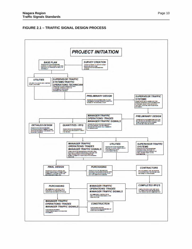
formal “sign-off” on the design modification list is not required, it may be beneficial for the designer to contact each review party to ensure that their issues and concerns have been properly recorded and documented. 2.3 Final Traffic Signal Design Once the list of design modifications has been compiled and confirmed, the designer may proceed with the final traffic signal design. The final design is to reflect the modifications identified by the review parties and the final drawing package must be produced in the format specified in this manual. Once complete, the final design package is to be circulated to the review parties for final approval. If major modifications are required to the final design, the review party must document these changes in writing and submit to the signal designer. The designer will modify the final design package, as required, and resubmit said package for a representative from Systems, Operations, and Engineering approval. If no modifications are required or only minor changes are necessary, the review must “sign-off” on the final design package and provide written notice to the signal designer indicating full approval or approval subject to minor modifications. Subsequent to final approvals being received from the review parties, contract packages must be prepared, approved by project manager, and the project tendered (or sent to purchasing). Should a conflict arise from within the reviewing parties, the final decision will be made by the Director Transportation Services Division or the Director’s designate. Subsequent to tender/RFQ submission the project manager notify the manager of traffic of the project status. 2.4 Traffic Signal Construction Subsequent to the award of the contract, the signal designer, Operations and the successful contractor, (if applicable), should meet on-site to locate the traffic signal plant. All aspects of the traffic signal design should be reviewed at this time to ensure that it is applicable to the field. If major modifications are required due to some unforeseen constraint, the signal designer must modify the design and resubmit a new traffic signal layout for construction purposes. All modifications made to the design package must be documented and circulated to all review parties for their records. If minor modifications are required in the field, they are to be noted and documented by the designer. Construction drawings do not have to be reissued for minor modifications. Once installation is complete, the signal designer must prepare the legal drawings for the intersection. The legal drawings must reflect the minor modifications made in the field and must be forwarded to the Director Transportation Services Division or the Director’s designate for final endorsement. A synopsis of the aforementioned design process has been provided in TABLE 2.1 and illustrated in FIGURE 2.1.
Niagara Region Traffic Signals Standards
Page 8
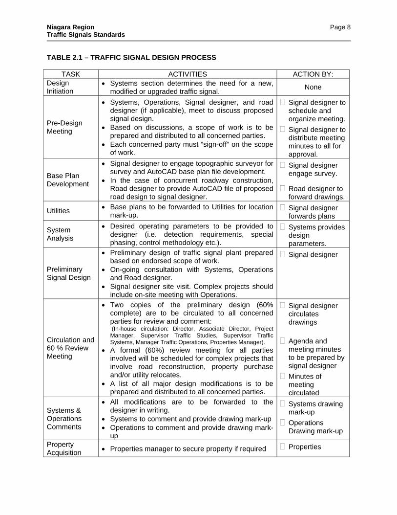
TABLE 2.1 – TRAFFIC SIGNAL DESIGN PROCESS
TASK ACTIVITIES ACTION BY: Design Initiation
Systems section determines the need for a new, modified or upgraded traffic signal.
None
Pre-Design Meeting
Systems, Operations, Signal designer, and road designer (if applicable), meet to discuss proposed signal design.
Based on discussions, a scope of work is to be prepared and distributed to all concerned parties.
Each concerned party must “sign-off” on the scope of work.
Signal designer to schedule and organize meeting.
Signal designer to distribute meeting minutes to all for approval.
Base Plan Development
Signal designer to engage topographic surveyor for survey and AutoCAD base plan file development.
In the case of concurrent roadway construction, Road designer to provide AutoCAD file of proposed road design to signal designer.
Signal designer engage survey.
Road designer to forward drawings.
Utilities Base plans to be forwarded to Utilities for location mark-up.
Signal designer forwards plans
System Analysis
Desired operating parameters to be provided to designer (i.e. detection requirements, special phasing, control methodology etc.).
Systems provides design parameters.
Preliminary Signal Design
Preliminary design of traffic signal plant prepared based on endorsed scope of work.
On-going consultation with Systems, Operations and Road designer.
Signal designer site visit. Complex projects should include on-site meeting with Operations.
Signal designer
Circulation and 60 % Review Meeting
Two copies of the preliminary design (60% complete) are to be circulated to all concerned parties for review and comment:
(In-house circulation: Director, Associate Director, Project Manager, Supervisor Traffic Studies, Supervisor Traffic Systems, Manager Traffic Operations, Properties Manager).
A formal (60%) review meeting for all parties involved will be scheduled for complex projects that involve road reconstruction, property purchase and/or utility relocates.
A list of all major design modifications is to be prepared and distributed to all concerned parties.
Signal designer circulates drawings
Agenda and meeting minutes to be prepared by signal designer
Minutes of meeting circulated
Systems & Operations Comments
All modifications are to be forwarded to the designer in writing.
Systems to comment and provide drawing mark-up Operations to comment and provide drawing mark-
up
Systems drawing mark-up
Operations Drawing mark-up
Property Acquisition Properties manager to secure property if required Properties

Niagara Region Traffic Signals Standards
Page 9
TABLE 2.1 – TRAFFIC SIGNAL DESIGN PROCESS CONTINUED
TASK ACTIVITIES ACTION BY:
90 % Design
Signal designer to complete 90% design drawings Signal designer to compete wiring diagram Signal designer to complete form of tender Signal designer to complete special provisions Signal designer to compile RFQ for signal projects. Signal designer to distribute documents for review
and approval.
Signal designer to forward all documents for review
Systems & Operations Approvals
A formal (90%) review meeting for all parties involved may be scheduled
Systems and Operations to review and approve drawings and documents.
Systems Approval
Operations Approval
Utilities Signal designer to apply to local hydro for pole spot location/approval
Signal designer
Final Signal Design
The design is modified based on compiled list of modifications. 100% design complete.
Contract documents for RFQ are forwarded to Operations for final check.
Operations to forward to Purchasing Department.
Signal designer
Operations to forward RFQ to Purchasing
Purchasing Purchasing Department to distribute RFQ to contractors.
Purchasing
Tender and Award
Operations to review submissions from contractors. Purchasing to award contract.
Operations
Purchasing
Field Layout
Contactor to layout signal components in the field (i.e. poles, ducts, junction boxes, controller etc.).
Operations to approve layout prior to construction. Written change order required for design
modifications.
Layout
Operations
Signal Installation Construction
Installation of all underground and above ground signal components by contractor.
If major modifications to the design are required, a written change order must be prepared and endorsed by the Designer, Systems and Operations.
New design drawings are to be prepared and circulated outlining all modifications.
Niagara Region Operations staff to complete traffic signal wiring connections.
Operations Inspector to mark-up drawings for as-constructed drawing update and submit to signal designer.
Construction
Operations
Inspector as-build drawing mark-up completion.
Prepare Final Drawings
Signal designer to prepare record drawing (PDF) as-constructed and wiring. File in: P:\PW_SIGNALS\Region\Record_dwg
Signal designer to prepare Legal approval drawing and distribute for signature. File in: P:\PW_SIGNALS\Region\Dwg-legal
Record drawing
Legal signal drawing
Niagara Region Traffic Signals Standards
Page 10
FIGURE 2.1 – TRAFFIC SIGNAL DESIGN PROCESS
Niagara Region Traffic Signals Standards
Page 11
3.0 NIAGARA REGION OPERATING PRACTICES The safe and efficient movement of vehicular and pedestrian traffic at a signalized intersection is not only dependent on the physical design of the traffic signal but also on how the traffic signal apportions time to conflicting flows and movements. This section of the manual outlines the Regional preferences for traffic signal operation. Topics discussed in this section include control methodologies, phasing requirements, detection methods and general timing parameters. Interconnection and emergency preemption are discussed as well.
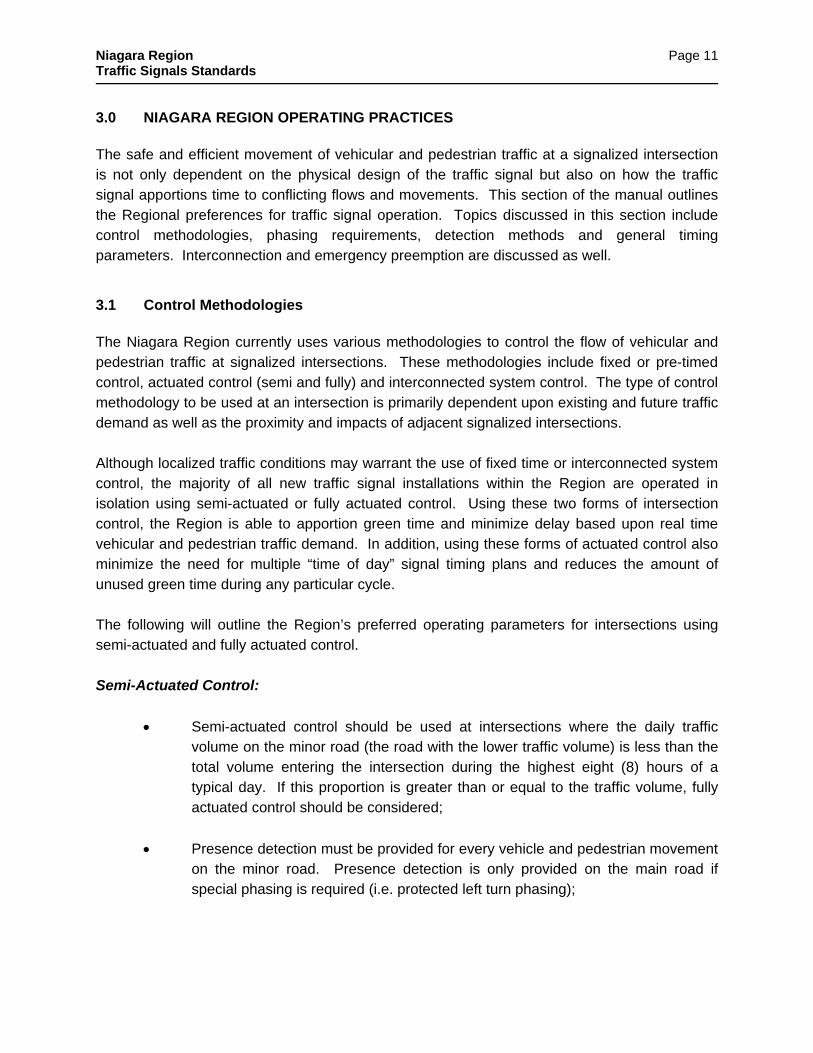
3.1 Control Methodologies The Niagara Region currently uses various methodologies to control the flow of vehicular and pedestrian traffic at signalized intersections. These methodologies include fixed or pre-timed control, actuated control (semi and fully) and interconnected system control. The type of control methodology to be used at an intersection is primarily dependent upon existing and future traffic demand as well as the proximity and impacts of adjacent signalized intersections. Although localized traffic conditions may warrant the use of fixed time or interconnected system control, the majority of all new traffic signal installations within the Region are operated in isolation using semi-actuated or fully actuated control. Using these two forms of intersection control, the Region is able to apportion green time and minimize delay based upon real time vehicular and pedestrian traffic demand. In addition, using these forms of actuated control also minimize the need for multiple “time of day” signal timing plans and reduces the amount of unused green time during any particular cycle. The following will outline the Region’s preferred operating parameters for intersections using semi-actuated and fully actuated control. Semi-Actuated Control:
Semi-actuated control should be used at intersections where the daily traffic volume on the minor road (the road with the lower traffic volume) is less than the total volume entering the intersection during the highest eight (8) hours of a typical day. If this proportion is greater than or equal to the traffic volume, fully actuated control should be considered;
Presence detection must be provided for every vehicle and pedestrian movement on the minor road. Presence detection is only provided on the main road if special phasing is required (i.e. protected left turn phasing);
Niagara Region Traffic Signals Standards
Page 12
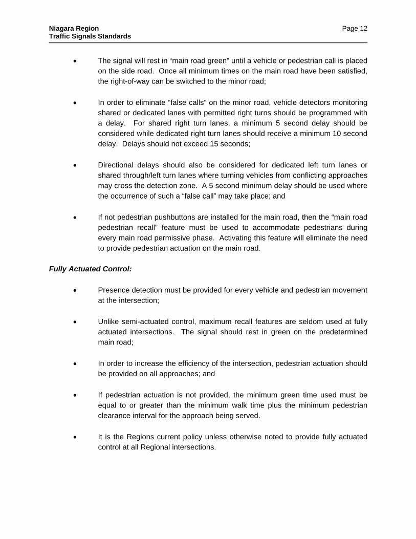
The signal will rest in “main road green” until a vehicle or pedestrian call is placed on the side road. Once all minimum times on the main road have been satisfied, the right-of-way can be switched to the minor road;
In order to eliminate “false calls” on the minor road, vehicle detectors monitoring shared or dedicated lanes with permitted right turns should be programmed with a delay. For shared right turn lanes, a minimum 5 second delay should be considered while dedicated right turn lanes should receive a minimum 10 second delay. Delays should not exceed 15 seconds;
Directional delays should also be considered for dedicated left turn lanes or shared through/left turn lanes where turning vehicles from conflicting approaches may cross the detection zone. A 5 second minimum delay should be used where the occurrence of such a “false call” may take place; and
If not pedestrian pushbuttons are installed for the main road, then the “main road pedestrian recall” feature must be used to accommodate pedestrians during every main road permissive phase. Activating this feature will eliminate the need to provide pedestrian actuation on the main road.
Fully Actuated Control:
Presence detection must be provided for every vehicle and pedestrian movement at the intersection;
Unlike semi-actuated control, maximum recall features are seldom used at fully actuated intersections. The signal should rest in green on the predetermined main road;
In order to increase the efficiency of the intersection, pedestrian actuation should be provided on all approaches; and
If pedestrian actuation is not provided, the minimum green time used must be equal to or greater than the minimum walk time plus the minimum pedestrian clearance interval for the approach being served.
It is the Regions current policy unless otherwise noted to provide fully actuated control at all Regional intersections.

Niagara Region Traffic Signals Standards
Page 13
3.2 Signal Phasing Like many road authorities responsible for the operation of traffic signals, the Region of Niagara uses various phasing schemes to control vehicular movement at intersections. The Region currently uses phasing as simple as a two-phase permissive scheme and as complex as an eight-phase protected/permissive scheme with simultaneous left turns. Localized traffic conditions will determine the type of signal phasing to be used at an intersection.
The following will outline the Region’s recommended parameters and preferences for traffic signal phasing:
The need for special left turn phasing is dependent upon localized traffic conditions, however, as a general rule, if the volume of left turns for any approach exceeds 200 vehicles per hour, a protected left turn warrant should be completed;
All left turn phasing must be protected/permissive or fully-protected “leading” left turn phasing. Permissive/protected or “lagging” left turn phasing is not encouraged;
Fully protected left turn phasing should only be used under extreme conditions such as high speed approaches or where there is poor visibility of on-coming traffic. It should also be considered where dual left turn lanes are present. Other forms of left turn phasing should be considered before implementing this measure;
The Systems section will determine the need for emergency vehicle, rail, or lift bridge preemption phasing;
Overlapping right turn phasing may be considered.
3.3 Vehicle Detection The Region currently uses an assortment of devices to provide vehicle detection at signalized intersections. The devices currently used by the Region include inductive loops, video, microwave, infrared and Doppler radar. Although the Region uses many devices, base course installed inductive loops are the preferred method of vehicle detection.
The following will outline the parameters that the Region uses for the detection of vehicles at a signalized intersection:

Niagara Region Traffic Signals Standards
Page 14
Loop detection should be used at all new traffic signal installations where funding permits and where can be installed in the base course asphalt;
The method for vehicle detection should be reviewed and evaluated on an intersection specific basis. The most effective method should be selected based on operating characteristics of the intersection and the cost of installation.
Where loop detection has been discarded as a viable detection method, overhead detection should be used;
Pulse detection is typically used to provide passage through the intersection using loops installed prior to the stop bar, while presence mode is generally reserved for stop bar detection and is the preferred mode of detector operation;
As stated earlier, in order to eliminate “false calls”, vehicle detectors monitoring shared or dedicated lanes with permitted right turns should be programmed with a delay. For shared right turn lanes, a minimum 5 second delay should be considered while dedicated right turn lanes should receive a minimum 10 second delay. Delays should not exceed 15 seconds.
Delays should also be programmed into dedicated left turn lanes where turning vehicles from conflicting approaches may cross the detection zone. A 5 second minimum delay should be used where the occurrence of such a “false call” may take place; and
On roadways with an operating speed of 80 km/h or greater, long distance detection should be used to provide dilemma zone protection.
3.4 Signal Timing Parameters Although the actual amount of green required for any one phase is dependent upon prevailing traffic conditions, the Region has identified a set minimum and maximum timing values that should be used when developing timing plans for Regional traffic signals. The values typically used by the Region are outlined below:

Niagara Region Traffic Signals Standards
Page 15
Signal Characteristic / Phase
Minimum Duration (seconds)
Maximum (seconds)
Cycle length 50.0 150.0
Pedestrian
Walk
Clearance
Phase time
7.0
7.0
14.0
N/A
Permissive Phase 8.0 50.0
Protected Left 5.0 N/A
Amber 4.1
(See OTM Book 12 2001)
All Red 2.0
Vehicle extensions or passage intervals are dependent on the distance of the detection zone from the stop bar. Unit extensions are typically in the 2 to 4 second range;
The minimum walk and clearance intervals for pedestrians must be calculated using accepted industry standards and must be at least equal to the minimum times specified in this manual. If the times calculated are higher than the minimum times specified in this manual, the higher values must be used;
The desirable cycle length is between 70.0 and 90.0 seconds;
The time used for the amber and all-red clearance intervals must be calculated using current MTO standards;
The minimum amber period used must not be less than 3.0 seconds and the minimum all-red clearance interval used must not be less than 2.0 seconds. Where the calculated amber and all-red intervals are higher than those prescribed in this manual, the higher values must be used; and
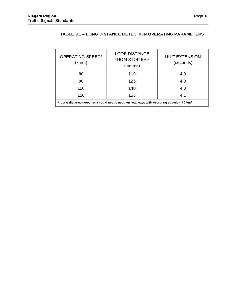
The loop placement and timing requirements for long distance detection should be based on the current Ontario Traffic Manual (OTM) Book 12 TABLE 3.1:
Niagara Region Traffic Signals Standards
Page 16
TABLE 3.1 – LONG DISTANCE DETECTION OPERATING PARAMETERS
OPERATING SPEED* (km/h)
LOOP DISTANCE FROM STOP BAR
(metres)
UNIT EXTENSION (seconds)
80 110 4.0
90 125 4.0
100 140 4.0
110 155 4.1
* Long distance detection should not be used on roadways with operating speeds < 80 km/h.
Niagara Region Traffic Signals Standards
Page 17
4.0 NIAGARA REGION DESIGN PRACTICES The key to an efficient and safe traffic signal installation is standardization and predictability. Drivers have certain expectations when approaching traffic signals. They know approximately where the signal heads should be; they understand the meaning and sequencing of various signal indications; and they anticipate certain events based on the geometry of the intersection and the state of the traffic signal within it. If one or more of these “expected” conditions is not present or is located in an unfamiliar position, the safety and efficiency of the signal installation decreases. It is the responsibility of the designer to ensure that the signal design meets the needs and expectations of the motoring public. Although the overall “look” of the signal installation will be dictated by the expected operation of the intersection as well as field constraints, the designer must be able to achieve a balance between wants and needs. Over designing a signal installation may degrade the operation and effectiveness of the intersection as much as under designing. Where traffic control signal studies indicate that traffic control signals are not required at the time of construction/reconstruction of the intersection, but will be required within five years, then the recommended practice is to construct underground provisions, in the form of ducts and electrical chambers, within the current intersection upgrade. Target value and the ability of the signal installation to relay the proper information to the motorist are the essential components of good design. Engineers need to be able to look at an intersection from the motorist’s point of view and to design and operate it in a way that will not surprise and confuse the driver. The purpose of this section is to provide the designer with some general and specific guidelines regarding the placement of various traffic signal components in order to achieve uniform, predictable and safe installations. Topics discussed in this section include signal head visibility and placement, pole location, pedestrian considerations, controller placement, detector layout, and grounding requirements. 4.1 Signal Head Visibility and Placement The visibility and placement of the primary and secondary signal heads within the intersection is critical to the overall safety and effectiveness of the signal installation. Approaching motorists must be able to view the signal heads from a sufficient distance to ensure that they can react to a changing or red signal indication. In addition, the signal heads must be located in predictable areas to ensure that motorists are not required to search the horizon to obtain the required information. Signal head visibility and placement often dictates where poles will be located and how many poles will be required. In order to achieve proper signal head visibility and placement, the following guidelines have been provided:

Niagara Region Traffic Signals Standards
Page 18
Based on the operating speed of the roadway, the primary and secondary signal heads should be visible from at least the minimum values prescribed in the O.T.M. Book 12 outlined in TABLE 4.1. If these minimum distances can not be obtained, an auxiliary signal head and/or a “signal ahead” warning sign should be used.
TABLE 4.1 – MINIMUM VISIBILITY DISTANCES
OPERATING SPEED (km/h)
VISIBILITY DISTANCE* (metres)
50 85
60 110
70 140
80 170
100 230
* Should be measured from the approach stop bar location
For motorists approaching the intersection, the primary signal head must be mounted within the motorist cone of vision extending 30-degree horizontal cone of vision (15-degree is desirable) and the secondary signal head mounted within a 40-degree horizontal cone of vision as illustrated in FIGURE 4.1.
FIGURE 4.1 – HORIZONTAL CONE OF VISION
Niagara Region Traffic Signals Standards
Page 19
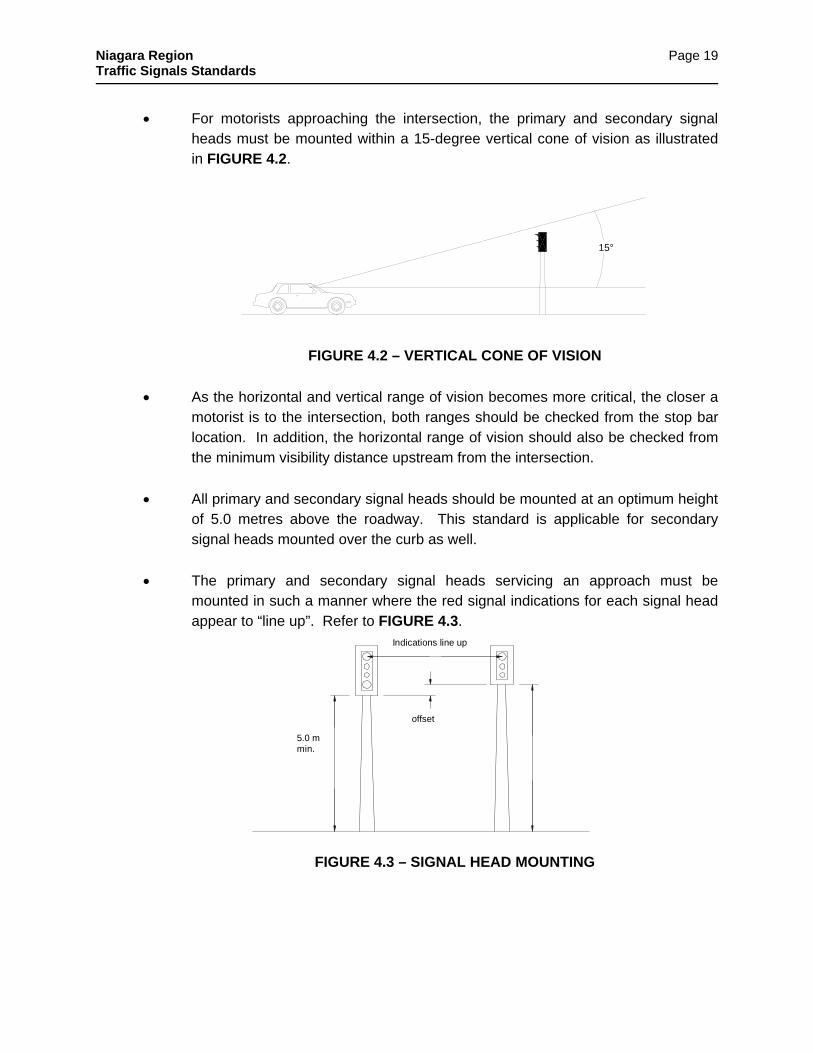
For motorists approaching the intersection, the primary and secondary signal heads must be mounted within a 15-degree vertical cone of vision as illustrated in FIGURE 4.2.
FIGURE 4.2 – VERTICAL CONE OF VISION
As the horizontal and vertical range of vision becomes more critical, the closer a motorist is to the intersection, both ranges should be checked from the stop bar location. In addition, the horizontal range of vision should also be checked from the minimum visibility distance upstream from the intersection.
All primary and secondary signal heads should be mounted at an optimum height of 5.0 metres above the roadway. This standard is applicable for secondary signal heads mounted over the curb as well.
The primary and secondary signal heads servicing an approach must be mounted in such a manner where the red signal indications for each signal head appear to “line up”. Refer to FIGURE 4.3.
FIGURE 4.3 – SIGNAL HEAD MOUNTING
15°
5.0 mmin.
offset
Indications line up

Niagara Region Traffic Signals Standards
Page 20
The primary signal head should be mounted at the ½ to ¾ point of the curb lane. Refer to FIGURE 4.4.
FIGURE 4.4 – PRIMARY SIGNAL HEAD PLACEMENT
If a median island is not present, the secondary signal head should be mounted over the curb or in a straight line extended from the curb.
Where a median island is present, the secondary signal head may be installed on a pole within the center median island. This is only advisable if the secondary signal head can be mounted at least 5.0m from the primary signal head.
During design, care should be taken to ensure that the secondary signal head servicing the approach in one direction does not block the motorist’s visibility of the primary signal head servicing the approach in the opposite direction. Refer to FIGURE 4.5.
FIGURE 4.5 – SIGNAL HEAD OFFSET
Niagara Region Traffic Signals Standards
Page 21
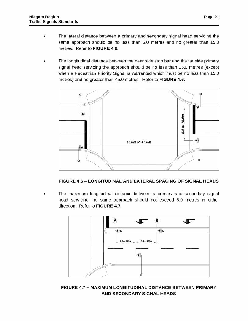
The lateral distance between a primary and secondary signal head servicing the same approach should be no less than 5.0 metres and no greater than 15.0 metres. Refer to FIGURE 4.6.
The longitudinal distance between the near side stop bar and the far side primary signal head servicing the approach should be no less than 15.0 metres (except when a Pedestrian Priority Signal is warranted which must be no less than 15.0 metres) and no greater than 45.0 metres. Refer to FIGURE 4.6.
FIGURE 4.6 – LONGITUDINAL AND LATERAL SPACING OF SIGNAL HEADS
The maximum longitudinal distance between a primary and secondary signal head servicing the same approach should not exceed 5.0 metres in either direction. Refer to FIGURE 4.7.
FIGURE 4.7 – MAXIMUM LONGITUDINAL DISTANCE BETWEEN PRIMARY AND SECONDARY SIGNAL HEADS
Niagara Region Traffic Signals Standards
Page 22
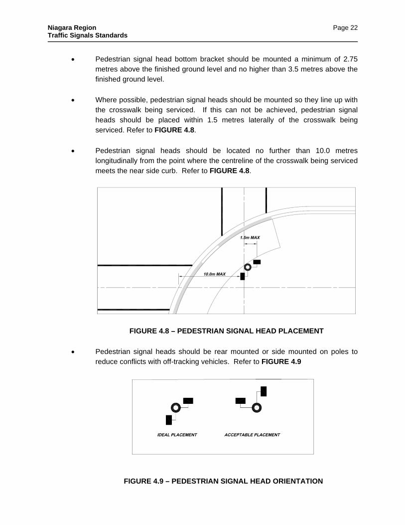
Pedestrian signal head bottom bracket should be mounted a minimum of 2.75 metres above the finished ground level and no higher than 3.5 metres above the finished ground level.
Where possible, pedestrian signal heads should be mounted so they line up with the crosswalk being serviced. If this can not be achieved, pedestrian signal heads should be placed within 1.5 metres laterally of the crosswalk being serviced. Refer to FIGURE 4.8.
Pedestrian signal heads should be located no further than 10.0 metres longitudinally from the point where the centreline of the crosswalk being serviced meets the near side curb. Refer to FIGURE 4.8.
FIGURE 4.8 – PEDESTRIAN SIGNAL HEAD PLACEMENT
Pedestrian signal heads should be rear mounted or side mounted on poles to reduce conflicts with off-tracking vehicles. Refer to FIGURE 4.9
FIGURE 4.9 – PEDESTRIAN SIGNAL HEAD ORIENTATION
Niagara Region Traffic Signals Standards
Page 23
4.2 Signal Pole Placement The placement of traffic signal poles within the intersection right-of-way is an iterative process that is based on many factors. Typically, the location of signal poles is largely dependent upon the guidelines related to primary and secondary signal head placement, however other factors, such as clear zone requirements, pedestrian considerations and existing intersection geometry may also influence this process. In general, signal poles should be located as far from the traveled portion of the roadway as possible without sacrificing signal head placement or drastically increasing mast arm length and costs. The number of signal poles used for any one installation should be kept to a minimum and the needs of both motorists and pedestrians must always be considered. In order to accurately locate traffic signal poles within the intersection right-of-way, the following guidelines have been provided:
It is Regional practice to provide dedicated poles for every traffic signal installation. Traffic signal heads and mast arms are not to be located on existing utility poles. Where existing light standards conflict or are in close proximity with the desired pole location, consideration should be given to relocating the luminaire to the traffic signal pole;
Poles should not be located within 3.0 metres of one another;
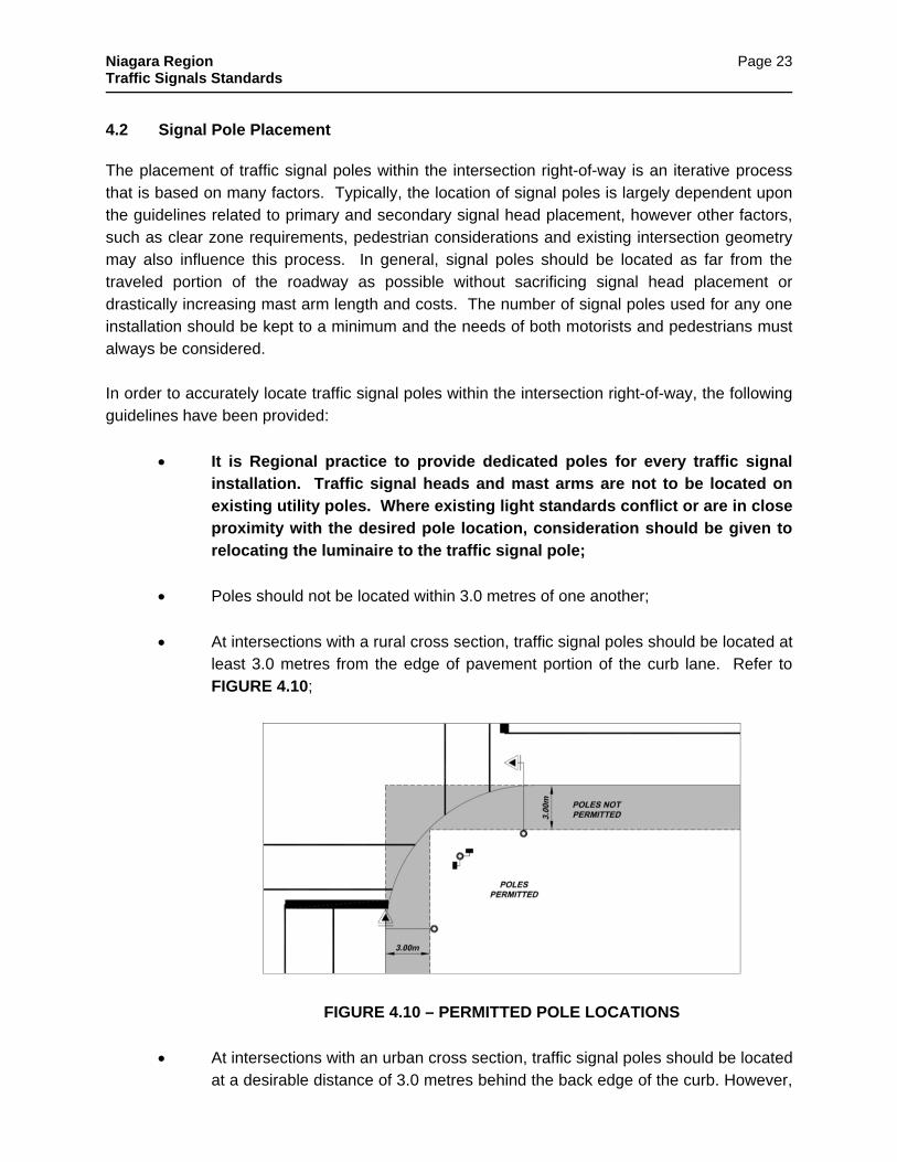
At intersections with a rural cross section, traffic signal poles should be located at least 3.0 metres from the edge of pavement portion of the curb lane. Refer to FIGURE 4.10;
FIGURE 4.10 – PERMITTED POLE LOCATIONS
At intersections with an urban cross section, traffic signal poles should be located at a desirable distance of 3.0 metres behind the back edge of the curb. However,

Niagara Region Traffic Signals Standards
Page 24
due to various constraints or conflicts, the pole may be located a minimum of 1.5 metres behind the back edge of the curb or 0.5 metres behind the back edge of a sidewalk. It is desirable to have the traffic signal pole located behind the sidewalk in all instances;
Where a secondary signal is to be located on a median island, the signal pole should be mounted in the centre of the island. The pole should also be located a minimum of 3.0 metres and a maximum of 5.0 metres from the front edge of the island. Refer to FIGURE 4.11.
FIGURE 4.11 – MEDIAN POLE PLACEMENT
Where pedestrian push buttons are being used, they should be mounted on the same pole as the pedestrian signal heads and must be at a height of one 1.1m above the ground level. Ref ONTARIO REGULATION 413/12 (s.80.28) Accessibility for Ontarians with Disabilities Act, 2005

Niagara Region Traffic Signals Standards
Page 25
Pedestrian push buttons must be located so that the pedestrian would not be required to travel more than 1.5 metres from the curb line at centerline of cross walk to push a button. Pedestrian push buttons should be located on the near side of the pole adjacent and parallel to the crosswalk it services. Refer to FIGURE 4.12;
FIGURE 4.12 – PEDESTRIAN PUSH BUTTON POLE PLACEMENT
Pedestrian push button poles should encroach 50% into a sidewalk apron or hard surface to accommodate physically challenged pedestrians and eliminate trampling of grassed areas around the push button pole.
Niagara Region Traffic Signals Standards
Page 26
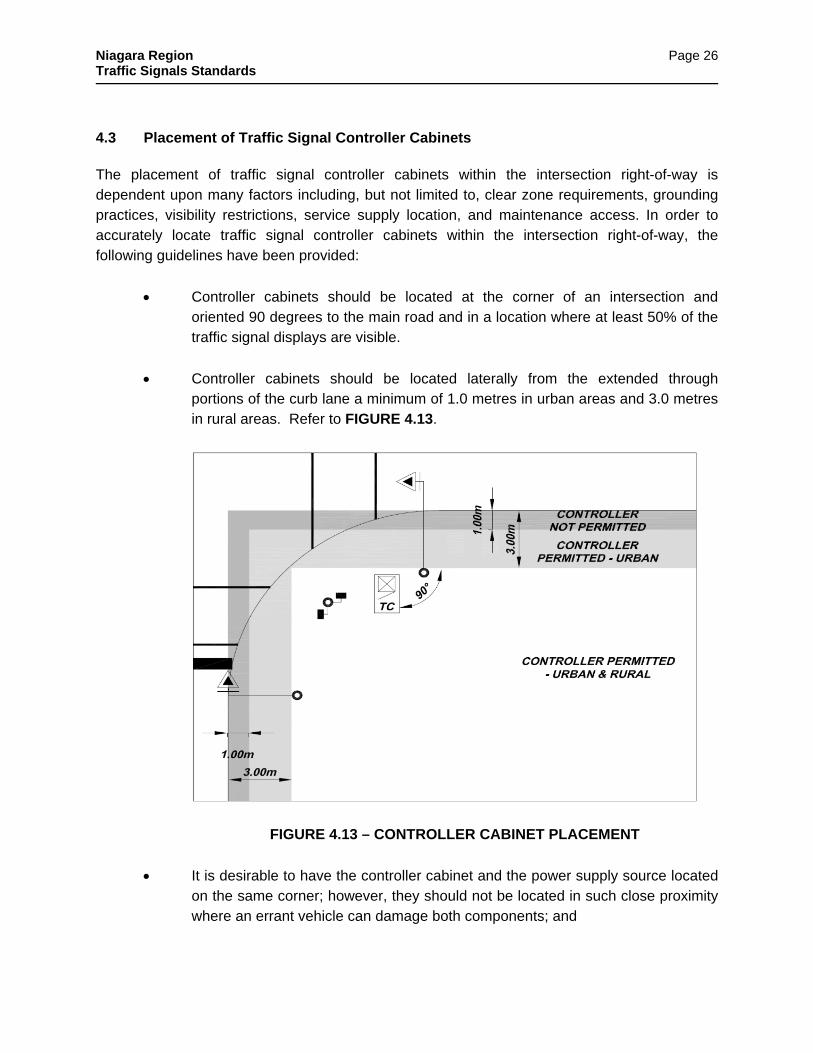
4.3 Placement of Traffic Signal Controller Cabinets The placement of traffic signal controller cabinets within the intersection right-of-way is dependent upon many factors including, but not limited to, clear zone requirements, grounding practices, visibility restrictions, service supply location, and maintenance access. In order to accurately locate traffic signal controller cabinets within the intersection right-of-way, the following guidelines have been provided:
Controller cabinets should be located at the corner of an intersection and oriented 90 degrees to the main road and in a location where at least 50% of the traffic signal displays are visible.
Controller cabinets should be located laterally from the extended through portions of the curb lane a minimum of 1.0 metres in urban areas and 3.0 metres in rural areas. Refer to FIGURE 4.13.
FIGURE 4.13 – CONTROLLER CABINET PLACEMENT
It is desirable to have the controller cabinet and the power supply source located on the same corner; however, they should not be located in such close proximity where an errant vehicle can damage both components; and
Niagara Region Traffic Signals Standards
Page 27
Where the controller cabinet and the power supply source are located on the same corner, the controller cabinet should be located at least 3.0 metres from the ground electrodes of the supply source.
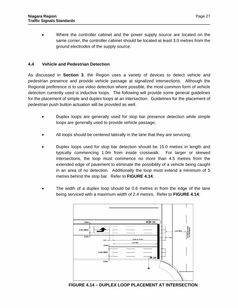
4.4 Vehicle and Pedestrian Detection As discussed in Section 3, the Region uses a variety of devices to detect vehicle and pedestrian presence and provide vehicle passage at signalized intersections. Although the Regional preference is to use video detection where possible, the most common form of vehicle detection currently used is inductive loops. The following will provide some general guidelines for the placement of simple and duplex loops at an intersection. Guidelines for the placement of pedestrian push button actuation will be provided as well.
Duplex loops are generally used for stop bar presence detection while simple loops are generally used to provide vehicle passage;
All loops should be centered laterally in the lane that they are servicing;
Duplex loops used for stop bar detection should be 15.0 metres in length and typically commencing 1.0m from inside crosswalk. For larger or skewed intersections, the loop must commence no more than 4.5 metres from the extended edge of pavement to eliminate the possibility of a vehicle being caught in an area of no detection. Additionally the loop must extend a minimum of 5 metres behind the stop bar. Refer to FIGURE 4.14;
The width of a duplex loop should be 0.6 metres in from the edge of the lane being serviced with a maximum width of 2.4 metres. Refer to FIGURE 4.14;
FIGURE 4.14 – DUPLEX LOOP PLACEMENT AT INTERSECTION

Niagara Region Traffic Signals Standards
Page 28
Protected permissive left turn lanes should have normal presence duplex loops at the stop bar and passage type loop (4.0 X 2.4 metres rectangular) placed one metre behind the stop bar detection loop.
Simple loops being used for long distance detection purposes should be 2.4 metres square with five (5) turns and centered in each through lane approaching the intersection. The loop should have a diamond orientation and be located from the stop bar based on the distances prescribed in TABLE 3.1. Refer to FIGURE 4.15; and
FIGURE 4.15 – LONG DISTANCE DETECTION LOOP PLACEMENT
4.5 Junction Boxes/Handholes and Traffic Ducts The following outlines the general requirements that should be used when locating junction boxes and traffic ducts within the right-of-way of a signalized intersection.
Traffic duct work is to be constructed to form a continuous loop around the intersection;
Wherever a grade or alignment change in the traffic duct system is encountered, a maximum of three 90-degree “sweeps” will be permitted to circumvent the obstacle;
Junction boxes must be located at all points where two or more duct systems intersect, where a major alignment change is required or at the back of a loop. A minimum of two junction boxes must be provided for each corner of the intersection (excluding junction boxes required for loop or interconnection feeds);
The number of junction boxes used for any installation should be kept to a minimum;
DISTANCE BASED ON OPERATING SPEED OF ROADWAY
REFER TO TABLE 3.1
LONG DISTANCE LOOP (2.4 m x 2.4 m)

Niagara Region Traffic Signals Standards
Page 29
Junctions boxes are to be placed on a bedding of clear stone for drainage supported by bricks placed on a 45-degree across each corner as shown in drawing NRS 2020; and
Junction boxes are typically installed a minimum of 1.0 metres from the back of curb or sidewalk and within 5.0 metres of the traffic signal pole base.
A separate 50mm communication system duct should be installed to the project
construction limits. 4.6 Grounding Requirements The following outlines the general grounding requirements for a typical Regional traffic signal installation:
The power supply source must be grounded using two grounding rods a minimum of three (3) meters apart;
Each pole at the intersection should be grounded using one 3-metre ground rod. The ground rod should be located in the junction box;
Where the controller cabinet and the power supply source are located on the same corner, the controller cabinet should be located at least 5.5 metres from the ground electrodes of the supply source;
4.7 Typical Design Layouts In order to provide the designer with some guidance when performing a traffic signal design for the Region, several “typical” layout examples have been developed. While it is impossible to provide examples for all situations, the layouts represent the most common application of the principles and practices outlined in this manual. The typical layout examples have been provided in APPENDIX G.
Niagara Region Traffic Signals Standards
Page 30
5.0 REGIONAL DESIGN AND CONSTRUCTION SPECIFICATIONS The Region relies on a number of documents including OPSS, OPSD, and NPSCD for much of the traffic signal design and construction specifications. The Region has also developed a set of supplementary special provisions that are considered unique to their operation. Appendix A contains the “Supplementary Special Provisions for Contract” which are referenced in design and form part of all traffic signal project contracts. These specifications and all referenced specifications within these documents are deemed to be included in the contact. 5.1 Regionally Approved Materials Listing In an effort to ensure that all new traffic signal installations are undertaken using standard, familiar and compatible components, the Region has prepared a list of pre-qualified materials and suppliers that must be used for all new traffic signal installations. It is the responsibility of the designer to ensure that the needs and requirements of these components have been accounted for in the signal design. It is the responsibility of the contractor to ensure that these materials are used in the field. Substitutions for any of these pre-approved components must not be made unless written approval has been received from the Region. It should also be noted that these pre-approved materials may change from time to time and it is the responsibility of the designer and contractor to ensure that their materials list is up to date. The full list of pre-approved materials and suppliers currently used by the Region for traffic signal installations can be found in APPENDIX C. 5.2 General Conditions The following section outlines the general conditions that must be satisfied when undertaking a traffic signal design or installation for the Region of Niagara. Where items are not discussed, the latest revisions of the NPSCD, OTM, OPSS and OPSD should be consulted.
All persons employed by the Contractor undertaking above ground traffic signal works for the Region should have successfully completed Level II of the International Municipal Signal Association’s (IMSA) Traffic Signal Technician Certification program. The Contractor should be able to provide proof of certification upon request;
The Contractor is responsible for workmanship of all equipment installed by the Contractor;
The Contractor may be required to supply the following materials and components:
Niagara Region Traffic Signals Standards
Page 31
Woven polypropylene rope fish with a minimum diameter of 6.35 mm (¼”) in all duct work;
Marrette-type butt connectors;
Stainless steel mounting strapping for signal brackets, push button assemblies, etc.;
Insulating and waterproofing tapes;
copper ground wires;
Pole sealing plugs for unused apertures; and
All materials provided by the Contractor must be approved by the Region before being used on site;
Materials being supplied by the Region must be obtained from the following:
Transportation Services Traffic Operations Public Works Service Centre 3547 Thorold Townline Road Thorold, Ontario Telephone: 905-685-1571, extension 2207
Fax: 905-227-0199 The store hours are from 8:00 a.m. to 2:00 p.m., Monday to Friday
Unless the Contractor has a secured storage area on the construction site, only material for two days’ work will be supplied at a time. The Contractor must also provide two working day’s notice of any materials required for the next day; and
A traffic signal inspector from the Region must be on-site at all times (or where determined by the Regional Project Manager as necessary) when traffic signal work is being undertaken. Normal working hours for the inspector are 8:00 a.m. to 4:00 p.m., Monday to Friday.
5.3 Above Ground Traffic Signal Works The following outlines the specifications that must be satisfied when designing or installing the above ground works associated with a Regional traffic signal installation. Items discussed in this section include, but are not limited to, signal heads, signal hangers, mast arms, poles, loop detectors, and signal cable. Where items are not discussed, the latest revisions of the OPSS and OPSD should be consulted.
Niagara Region Traffic Signals Standards
Page 32
5.3.1 Traffic Signal Heads
Traffic signal heads and hangers, pre-approved by the Region, must be used. Refer to Approved Material Listing;
The type of signal head to be installed and the location of each signal head must be as identified on the contract drawings;
The maximum number of sections for any one signal head must not exceed four (4);
Where special phasing is required (i.e. protected left turn phasing), the protected or special phase is to be displayed with a four (4) section signal head with a 30 cm LED green/amber arrow indication (TYPE 12 signal head);
Where two or more signal heads require special LED indications, the indications for every signal head, including pedestrian heads, at the intersection must be all 30 cm LED;
Pedestrian heads shall consist of the section head, bimodal LED, and countdown;
All primary and secondary signal heads must be mounted at a height where the bottom of the backboard for the signal head is at least 5.0 metres from the road surface;
All signal heads must be covered with burlap or black plastic bags while mounted in place, but not in operation. Pedestrian heads may be turned facing in as an alternative instead of the covering method; and
All devices used to fasten signal heads to mast arms or double arm brackets must be installed as per the manufacturer’s specifications.
5.3.2 Traffic Signal Arms
Traffic signal arms, pre-approved by the Region, must be used. Refer to the Approved Material Listing;
The length of each traffic signal arm must be as outlined on the contract drawings; and
Traffic signal arms must be installed as per the manufacturer’s specifications;
Pole plate brackets must be fastened to traffic signal poles using one zinc coated ¼ X 1 ¼” self tapping screw.
Niagara Region Traffic Signals Standards
Page 33
5.3.3 Traffic Signal Poles
Traffic signal poles, pre-approved by the Region, must be used. Refer to Approved Material List, Appendix C
The height and location of each traffic signal pole must be as outlined on the contract drawings. Poles are to be numbered in a clockwise direction commencing at the controller cabinet.
Poles should be 7.0 metres in height unless illumination is required. Poles with illumination should be 10.5 metres in height. Where utility conflicts exist and the minimum separation between overhead utility plants cannot be achieved, 6.3 metre poles may be used;
Poles should be located 3m vertical and horizontal away from any hydro utility lines (primary and secondary lines).
Where signal mast arm lengths exceed 5.5 metres, a pole height of 6.3 metres using minimum of type 6 pole should be used;
Where traffic signal poles are perforated for cables or cut for any reason, they must be treated with a zinc rich compound and fitted with rubber grommets;
Traffic signal poles must be installed as per the manufacturers’ specifications;
Pole sections must be fastened to each section using one stainless steel ¼ X 1 ¼” tapping screw; and
Traffic signal poles should be installed in such manners that the hand holes are facing away from the direction of traffic unless otherwise noted or directed in the field.
Pole plates (mast arm brackets) should be installed at the location where pole sections overlap unless otherwise directed in the field.
5.3.4 Pedestrian Push Buttons and Signs
Pedestrian signal heads and buttons must be installed at all traffic signal locates where pedestrians could be expected;
Each push button and sign must be placed on the poles as indicated on the contract drawings and must be mounted at a height of 1.08 metres from the finished ground level;
Audible pedestrian signals should be used at all locations;

Niagara Region Traffic Signals Standards
Page 34
A countdown section for pedestrian signals should always be used.
Pedestrian push button and push button signs, pre-approved by the Region, must be used. Refer to Approved Material Listing; and
Pedestrian push buttons and signs must be installed as per the manufacturer's specifications.
Pedestrian push buttons require a separate 2 conductor cable pulled in running back to controller cabinet for each pedestrian button.
5.3.5 Traffic Signal Cable and Wiring
Traffic signal cable, pre-approved by the Region, must be used. Refer to Approved Material Listing;
The Region uses a 25-conductor signal cable (CSA Approved) designed specifically for Niagara’s use;
Signal cable runs must be continuous between poles. Signal cable splices must only be made at poles. No signal cable splices are permitted below ground;
Sufficient length of free cable must be left in pole hand hole or junction boxes to allow a proper connection to be made with cable coming from signal and/or pedestrian heads;
Where secondary signals exist on median islands , the signal must not be wired using the main 25-conductor feed. Depending upon the direction of the main feed, a separate 7-conductor cable must be run back to service the median island pole from auxiliary pole; and
Cable connections must be connected using approved weather type Marrette connectors.
5.3.6 Vehicle Detection
Vehicle detection devices, pre-approved by the Region, must be used. Refer to Approved Material Listing;
Inductive loop feeds crossing barrier curb must be installed in flexible 19mm conduit below the curb as shown in Niagara Region Standard (NRS) Drawing 2520;

Niagara Region Traffic Signals Standards
Page 35
Inductive loop feeds should be made at the back edge of the loop (upstream from the intersection);
Where inductive loops are used, loop feeders must be tagged and terminated at the controller cabinet. 1.5 metres of slack coil must be provided at the base of the controller cabinet or pole base; and
Emergency vehicle preemption will be included in the traffic signals where required.
All vehicle detection devices should be installed as per the manufacturer’s specifications.
5.3.7 Power Feed and Disconnect
All devices/components used for the power feed and disconnect must be pre-approved by the Region. Refer to Approved Material Listing;
The power feed and disconnect must be installed as shown in NRS 2011, NRS 2012, NRS 2130, and/or NRS 2440;
Approval by the Electrical Safety Authority; and
Connected by the Local Power Authority.
5.3.8 Intersection Illumination and Wiring
Illumination wiring shall be run in a separate conduit assigned for low voltage cable in a common trench with the traffic signal conduit;
Luminaries shall be located on the far right side of the intersection of each leg;
Illumination cable will be RWU 90 consisting of #6 white, #6 black, #6 red;
Illumination shall be activated through a centrally located photoelectric controller with a separate circuit breaker for relamping, as per NRS-2440; and
The photoelectric controller shall be mounted on the supply control cabinet pole – NRS-2130.
5.3.9 Traffic Signal Control Cabinet
Traffic signal cabinet will be provided by Niagara Region and must include all current Niagara Region equipment standards.
Niagara Region Traffic Signals Standards
Page 36
5.4 Underground Traffic Signal Works The following section outlines the specifications that must be satisfied when designing or installing the underground works associated with a Regional traffic signal installation. Items discussed in this section include, but are not limited to, pole bases, anchorage assemblies, junction boxes, duct work, and controller bases. Where items are not discussed, the latest revisions of the OPSS and OPSD should be consulted.
5.4.1 Concrete Pole Bases
Concrete pole bases will vary according to the signal pole assembly length, number of mast arms, luminaire requirements, and soil conditions at the location where the base is being installed;
The concrete for constructing the footing shall be 30 MPa of 28 days, except that a retarder supplement is added to prevent temporary set for a period of four hours;
Concrete pole bases must be constructed and installed as shown in NRS 2002;
Anchorage assemblies used for concrete pole bases must be constructed and installed as shown in NRS 2001; and
Only Type 5, Type 6 or Type 8 pole bases should be used. Type 3 pole bases may be used where clearance restraints exist or where Pedestrian Heads & Buttons combinations are required.
5.4.2 Concrete Controller Bases
Concrete controller bases must be constructed and installed as shown in NRS 2003-M or NRS 2003-p using 30 Mpa of 28 days.
5.4.3 Traffic Ducts
Traffic ducts, pre-approved by the Region, must be used.
All traffic ducts must be installed with 6.35 mm (1/4”) diameter woven polypropylene fish line rope;
Main ducts between junction boxes, pole bases and the controller must be 100 mm in diameter;

Niagara Region Traffic Signals Standards
Page 37
Ducts used for the main power feed, illumination, loop feeders, push button feeds, and interconnection feeds must be 50 mm in diameter;
Where the existing pavement is disturbed, it must be reinstated to match the existing road structure. Asphalt must be replaced to full depth in lifts of 80mm maximum. Granular material must be “Granular A” and compacted in accordance with OPSD 501.
All ducts entering junction boxes should extend up 100 mm from the bottom of the junction box and ensuring a minimum of 75 mm separation from top of the protruding ducts to the junction box lid;
50mm Interconnect conduit to be installed 0.6m to 1.0m below finished grade;
All duct work is to be installed directly on the sub-grade elevation when trenching for the duct is constructed in an existing road;
Where ducts have been installed as spares, they must be capped to ensure that they remain free of debris.
5.4.4 Junction Boxes
Junction boxes, pre-approved by the Region, must be used. Refer to Approved Material Listing;
Junction boxes must be installed as shown in NRS 2020; and
Junction boxes are to be numbered in a clockwise direction commencing at the controller cabinet.
Niagara Region Traffic Signals Standards
Page 38
6.0 ENGINEERING SUBMISSION REQUIREMENTS 6.1 General The Niagara Region requires a complete submission of Engineering Drawings and Specifications to be provided by the Consulting Engineer for technical review, comment and approval. A complete submission constitutes the following items:
A letter of transmittal;
Engineering design brief;
Traffic Signal Design Checklist - Completed
Engineering drawings in hard copy and electronic file format;
Contract documents; and
Construction cost estimate. 6.2 Letter of Transmittal This letter can be a standardized form or formal letter indicating the submission date and number, contents of the submission package, and the name of the appropriate contact personnel. 6.3 Engineering Design Brief The engineering design brief is a technical report summarizing the intent of the project and outlines the design assumptions, calculations, supporting documentation and references to previous studies, for each component of the project. 6.4 Drawings
6.4.1 Electronic File
Pre-qualified engineers will be issued Region of Niagara Standards in an electronic file format. These standards can in no way be distributed or sold to any other outside agency; and
Drawings submitted must conform to all hard copy requirements and drawn in UTM co-ordinates.
Niagara Region Traffic Signals Standards
Page 39
6.4.2 Hardcopy
Drawing size shall be A1 (600mm X 900mm)-full scale;
Plans - minimum horizontal metric scale shall be 1:200;
Original material used for all drawings shall be Mylar Mat surface on working side or equivalent;
All drawings and tables shall be neat, legible and completed in ink;
All drawings must contain a key plan, north arrow, current revision status and be stamped by an Engineer licensed to practice in the Province of Ontario;
Roadway, entrances, walkways, utilities (above and below ground), all appurtenances, and pavement markings existing shall be shown on all drawings;
Proposed traffic signal requirements, including material information (pole, mast arm, signal head, bracket, luminaire), detection requirements, hand hole locations, electrical duct locations, traffic signal phasing, controller connection data, signal heads wiring connections data, and general wiring diagram shall be shown on the appropriate drawings; and
Where plans require more than one drawing, match lines shall be provided with no overlapping of information.
6.5 Contract Drawings
A complete set of drawings for submission shall include:
(i) Title Sheet; (ii) Traffic Signal Construction Drawing (iii) Wiring Diagram Detail; and (iv) Electrical Detail Drawings (Non- Standard if required).
6.5.1 Title Sheet
The Title Sheet shall include the following:
Name of Project;
Name of Municipality work is being undertaken in;
Region of Niagara;
Name of Regional Chair;
Name of Director of Public Works;
Name of Consulting Engineer;
Key Plan at a scale of 1:10,000 indicating the location of the proposed construction; and
Index to each drawing constituting the complete set indicating drawing number and title.

Niagara Region Traffic Signals Standards
Page 40
6.5.2 Traffic Signal Construction Drawing
To a scale of 1: 200 showing the following:
Roadway, entrances, walkways, utilities (above and below ground), and all appurtenances;
Pavement markings;
Proposed traffic signal requirements, including type of pole bases and material information (pole, mast arm, signal head, bracket, luminaire);
Junction Box location and number;
Electrical duct locations (number of ducts, size, type);
Proposed traffic signal detection requirements, including type (overhead, or loops-location number and size);
6.5.3 Wiring Diagram Detail
The Wiring Diagram Detail Drawing shall include the following:
Legend table, identifying drawing symbols as well as cables including, type of cable, gauge, number of conductors and colour/marks;
General Notes for construction;
Supply Control Cabinet Assembly load table identifying size of breaker for each circuit required and load;
Controller connections identifying detection device type and number;
Supply control cabinet assembly
Information identifying pole, type of head and luminaires; and
Wire diagram or schematic identifying individual wiring configurations to the controller signal heads and activators running through electrical ducts including the number of conductors, colour and point of contact
6.5.4 Electrical Detail Drawings (Non Standard if required)
6.6 Contract Documents Upon final Engineering submission for approval of the Engineering Drawings, two paper copies and a PDF file copy of the Contract Documents for the project, in their final form, are required to be provided and approved by the Niagara Region. The contract documents will include:
Instructions to bidders
Form of Tender
Niagara Region Traffic Signals Standards
Page 41
Supplementary Special Provisions
Drawings Prior to commencement of construction, a further three (3) copies of the Contract Documents are required to be provided including two (2) reduced sets (50% reduction) of Contract Drawings to the Region’s Public Works Department. 6.7 Cost Estimate An itemized cost estimate for the construction of the works in a form acceptable to the Region of Niagara is required along with a breakdown of any items designated to be cost-shared. 6.8 Pre-Construction Meeting A pre-construction meeting with a representative from the consulting engineer, contractor, utility companies, local municipality, and Niagara Region shall be held for the purpose of co-ordinating all phases of construction relating to the project. 6.9 Record (As-constructed) Drawings Upon preliminary acceptance of services a record (as-constructed) drawing set will be completed and submitted to the Region. This information shall be provided in two electronic file formats (AutoCAD and PDF) as well as a paper hard copy. The AutoCAD file will be in the Niagara Peninsula CAD Standards format. The PDF drawing will be a two page PDF file with the Construction Record drawing as the first sheet and the Wiring Record Drawing as the second sheet. The Record (As-constructed) drawing set is required for the following: i) Construction Record Drawing
Plotted on a Construction Broader
Is an as-constructed drawing showing the new location of all traffic signal plant and surrounding detail;
Location of traffic signal plant including type of pole bases and material information (pole, mast arm, signal head, bracket, luminaire);
Junction box locations; and
Electrical duct locations including material information (number of ducts, size, type).
Detector detail showing vehicle and pedestrian detection type (overhead, or loops-location and size);

Niagara Region Traffic Signals Standards
Page 42
ii) Wiring Record Drawing
Legend table, identifying drawing symbols as well as cables including, type of cable, gauge, number of conductors and colour/marks;
General Notes for construction;
Supply Control Cabinet Assembly load table identifying size of breaker for each circuit required and load;
Controller connections identifying detection device type and number;
Supply control cabinet assembly
Information identifying pole, type of head and luminaires; and
Wire diagram or schematic identifying individual wiring configurations to the controller signal heads and activators running through electrical ducts including the number of conductors, colour and point of contact
6.10 Legal Approval Drawings (Formerly PHM-125 Drawings) Upon final acceptance of services and prior to actuation, the required Legal Approval Drawings are to be completed and submitted to the Region showing all necessary details for traffic signal installations. This information shall be provided in an electronic file format as well as hard copy. Recommended Practice i) The Legal Approval Drawings should be produced to a scale of 1:200. The plans should
show the intersection details on all approaches for the distance from the intersection, which directly affects the signal operation (usually not less than 30 m) and should indicate, to scale, the following (minimum) details:
All above ground traffic signal plant, luminaires and junction boxes;
Power pole and disconnect;
Edge of roadway (edge of pavement or curb and gutter), sidewalks, curb cuts, islands;
All regulatory or warning signage related to the traffic signal;
Property access (driveways, curb cuts, ramps);
Utility poles;
The exact location, orientation and type of traffic signal heads and their mounting height;
The exact location and orientation of pedestrian signal heads and pushbuttons;
Pavement markings (centre-line, lane lines, crosswalks, stop bars , turn arrows);
Blank-out signs and active or continuous flashing advance warning signs or other types of equipment operated by the signal controller;
Detection devices and their location;
Niagara Region Traffic Signals Standards
Page 43
Location of traffic signal controller cabinet;
Property lines, street names, building outlines, parking meters and parking control;
Bus bays and bus stops;
North Arrow;
Overhead traffic signal cable. If signal heads are relocated or, if additional signal heads are installed, then re-approval of the entire installation is required by the designated approval person. Legal Approval Drawings should be prepared for both temporary and permanent signals. 6.11 Update for Traffic Signal Drawings At the time of RFQ or tender:
1) A PDF of the Construction Drawing (including wiring diagram) will be copied to the P:\PW_SIGNALS\Region\Dwg-legal\ folder and to the P:\PW_SIGNALS\Region\Record_dwg\ folder.
2) The name of the PDF Construction Drawing will be the intersection code (ie. 087VNE) followed by “_Construction” (ie: 087VNE_Construction).
At the completion of the construction project (when the signal is built):
3) The inspector or lead hand will submit the construction mark-up drawings (construction and wiring) to the design technician.
4) The Design Technician will contact the Survey Department for an updated survey of the location of the traffic signal.
5) A record drawing will be developed and a PDF placed in the P:\PW_SIGNALS\Region\Record_dwg\ folder with a name format of the intersection code followed by “_Record” (ie: 005KNG_Record). This drawing will be a two page PDF. Page 1 an as-constructed copy of the construction drawing and page 2 an as-constructed wiring diagram.
6) The existing construction PDF in the Record folder will be removed following the addition of the “_Record” PDF.
7) A legal signal drawing will be developed from the construction drawing CAD file and copied to the P:\PW_SIGNALS\Region\Dwg-legal\ folder with the intersection code followed by “_(unsigned)” (ie: 003ELM(unsigned)).
8) The construction PDF in the Legal folder will then be removed following the addition of the “_(unsigned)” PDF.
9) The existing legal drawing will not be removed but will stay in the folder until an updated signed copy of the legal replaces it.
Niagara Region Traffic Signals Standards
Page 44
At the time a new legal has been signed:
10) The signed drawing should be scanned into PDF format and moved to the P:\PW_SIGNALS\Region\Dwg-legal\ folder. The name of this file will be the intersection code only (ie: 003ELM).
11) When a legal drawing is being replaced by an update the old drawing should be renamed with the intersection code followed by the date it was superseded (ie: 001RDG_2007-09-25) and the file must be moved to the P:\PW_SIGNALS\Region\Dwg-legal\SUPERSEDED\ folder as a past record of the intersection layout.
**The above examples are for regional projects. Any municipal projects will be located in the P:\PW_SIGNALS\Municipal\ folder.

APPENDIX A:
SUPPLEMENTARY SPECIAL PROVISIONS
FOR CONTRACT


APPENDIX B:
DETAIL DRAWINGS


APPENDIX C:
APPROVED MATERIALS LISTING

APPENDIX D:
TRAFFIC SIGNAL WIRING ASSIGNMENTS
AND MARKING


APPENDIX E:
REVIEW SHEETS


APPENDIX F:
QUICK REFERENCE GUIDES


APPENDIX G:
TYPICAL DRAWINGS