TKT-1212 Digitaalijärjestelmien toteutus · TKT-1212 Dig.järj.tot., kevät 2008, A. Kulmala, TTY...
56
Lecture 7: VHDL Testbenches Ari Kulmala, Erno Salminen 2008 TKT-1212 Digitaalijärjestelmien toteutus
Transcript of TKT-1212 Digitaalijärjestelmien toteutus · TKT-1212 Dig.järj.tot., kevät 2008, A. Kulmala, TTY...
Lecture 7: VHDL Testbenches
Ari Kulmala, Erno Salminen 2008
TKT-1212 Digitaalijärjestelmien toteutus
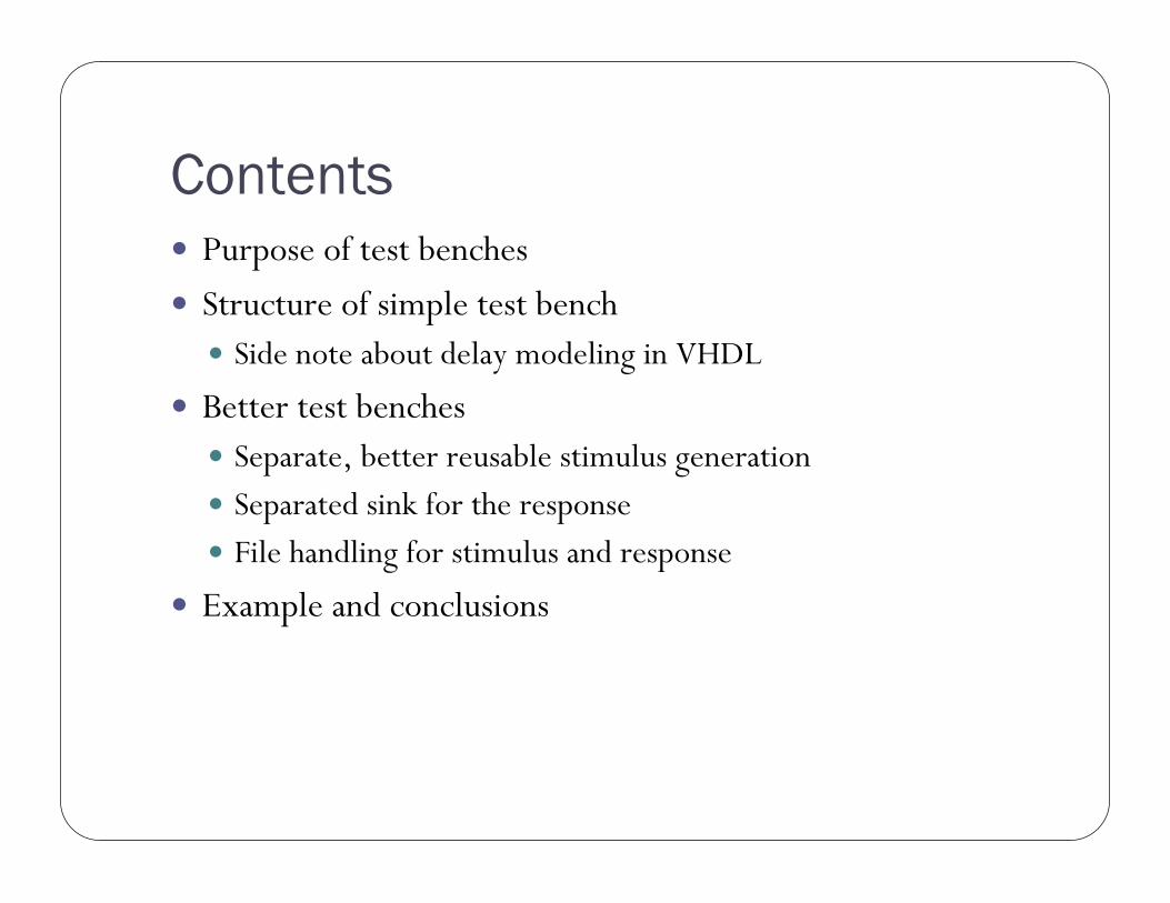
ContentsPurpose of test benches
Structure of simple test benchSide note about delay modeling in VHDL
Better test benchesSeparate, better reusable stimulus generationSeparated sink for the responseFile handling for stimulus and response
Example and conclusions
Introduction
3
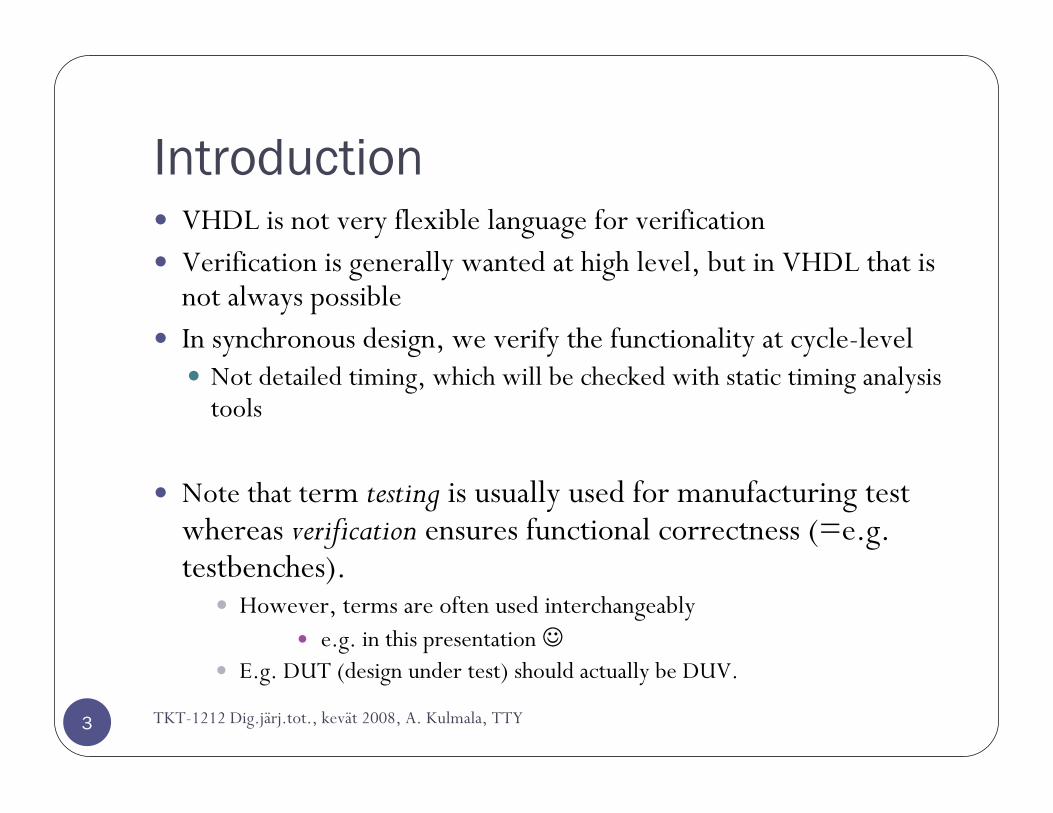
VHDL is not very flexible language for verificationVerification is generally wanted at high level, but in VHDL that is not always possibleIn synchronous design, we verify the functionality at cycle-level
Not detailed timing, which will be checked with static timing analysis tools
Note that term testing is usually used for manufacturing test whereas verification ensures functional correctness (=e.g. testbenches).
However, terms are often used interchangeablye.g. in this presentation ☺
E.g. DUT (design under test) should actually be DUV.
TKT-1212 Dig.järj.tot., kevät 2008, A. Kulmala, TTY

What Is The VHDL Test Bench (TB)?
4
VHDL test bench (TB) is a piece of code meant to to verify the functional correctness of HDL model.The main objectives of TB is to:
1. Instantiate the design under test (DUT)2. Generate stimulus waveforms for DUT3. Generate reference outputs and compare them with the outputs of
DUT4. Automatically provide a pass or fail indicationTest bench is a part of the circuits specification.Sometimes it’s a good idea to design the test bench before the DUT
Functional specification ambiguities foundForces to dig out the relevant information of the environmentDifferent designers for DUT and its tb!
TKT-1212 Dig.järj.tot., kevät 2008, A. Kulmala, TTY
Stimulus and Response
5
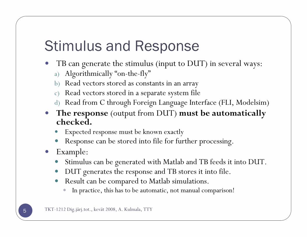
TB can generate the stimulus (input to DUT) in several ways:a) Algorithmically “on-the-fly”b) Read vectors stored as constants in an arrayc) Read vectors stored in a separate system filed) Read from C through Foreign Language Interface (FLI, Modelsim)The response (output from DUT) must be automatically checked.
Expected response must be known exactlyResponse can be stored into file for further processing.
Example:Stimulus can be generated with Matlab and TB feeds it into DUT.DUT generates the response and TB stores it into file.Result can be compared to Matlab simulations.
In practice, this has to be automatic, not manual comparison!
TKT-1212 Dig.järj.tot., kevät 2008, A. Kulmala, TTY
TKT-1212 Dig.järj.tot., kevät 2008, A. Kulmala, TTY
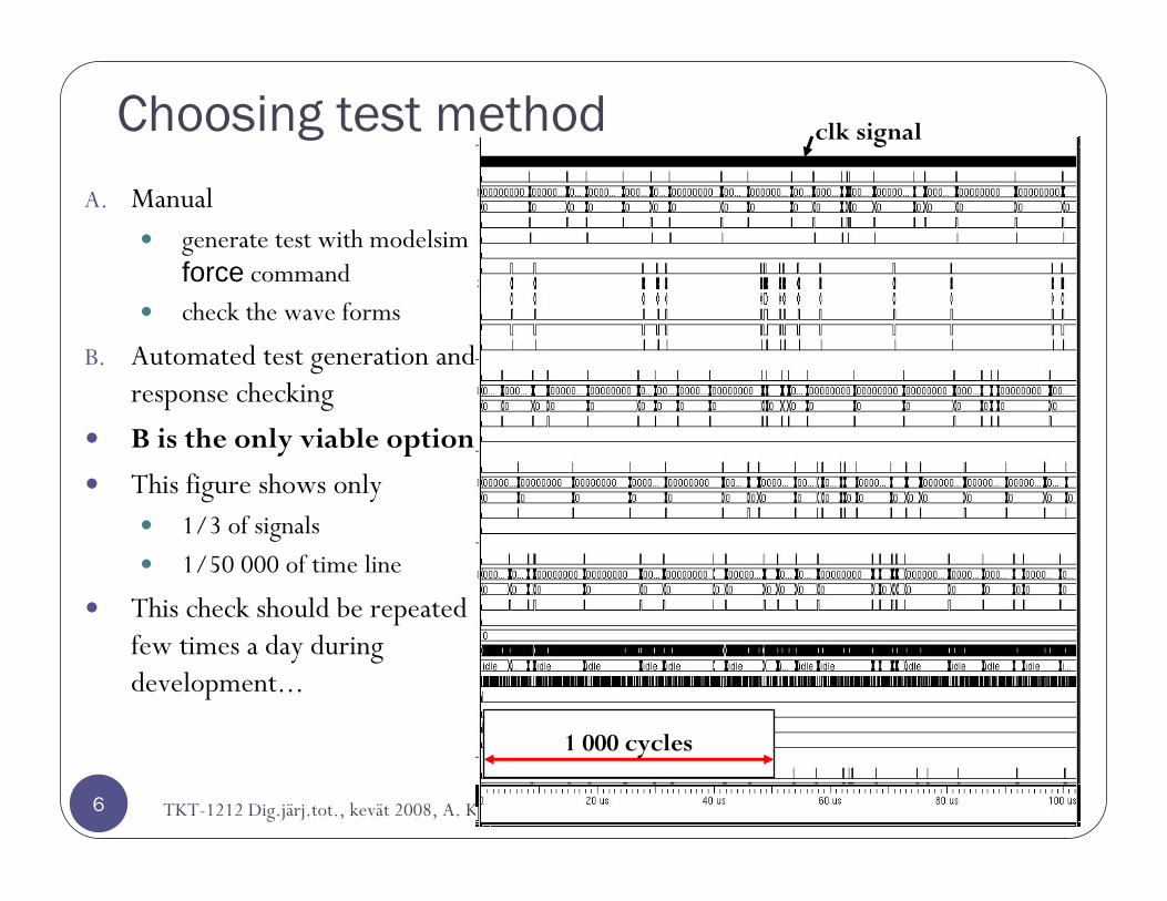
Choosing test methodA. Manual
generate test with modelsim force commandcheck the wave forms
B. Automated test generation and response checking
B is the only viable option
This figure shows only 1/3 of signals
1/50 000 of time line
This check should be repeated few times a day during development...
1 000 cycles
clk signal
6
Test Bench Structures
7
TB should be reusable without difficult modifications.Modular design
The structure of the TB should be simple enough so that other people understand its behaviour.
It has to be easy to runNot much dependencies on files or scripts
Good test bench propagates all the generics and constants into DUT.
Question: How to verify that the function of the test bench is correct? A: “sanopa muuta kato”
TKT-1212 Dig.järj.tot., kevät 2008, A. Kulmala, TTY
Simple Test Bench
8
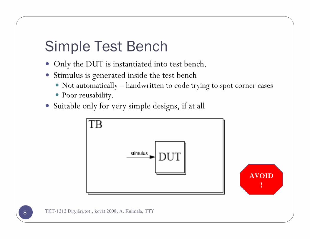
Only the DUT is instantiated into test bench.Stimulus is generated inside the test bench
Not automatically – handwritten to code trying to spot corner casesPoor reusability.
Suitable only for very simple designs, if at all
TKT-1212 Dig.järj.tot., kevät 2008, A. Kulmala, TTY
AVOID!
stimulus
A Simple Test Bench (2)
9
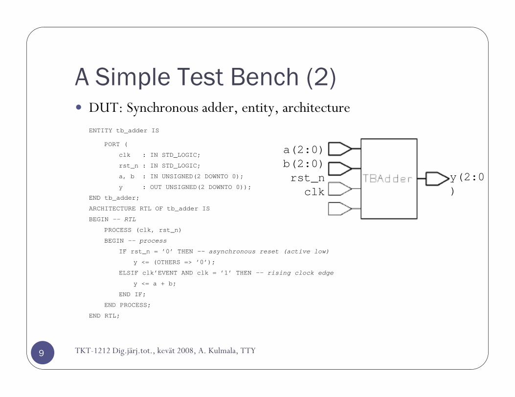
DUT: Synchronous adder, entity, architectureENTITY tb_adder IS
PORT (
clk : IN STD_LOGIC;
rst_n : IN STD_LOGIC;
a, b : IN UNSIGNED(2 DOWNTO 0);
y : OUT UNSIGNED(2 DOWNTO 0));
END tb_adder;
ARCHITECTURE RTL OF tb_adder IS
BEGIN -- RTL
PROCESS (clk, rst_n)
BEGIN -- process
IF rst_n = ’0’ THEN -- asynchronous reset (active low)
y <= (OTHERS => ’0’);
ELSIF clk’EVENT AND clk = ’1’ THEN -- rising clock edge
y <= a + b;
END IF;
END PROCESS;
END RTL;
a(2:0)b(2:0)rst_nclk
y(2:0)
TKT-1212 Dig.järj.tot., kevät 2008, A. Kulmala, TTY
A Simple Test Bench (3)
10
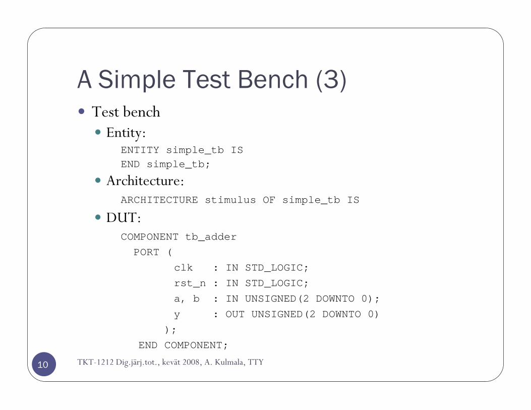
Test benchEntity:
ENTITY simple_tb ISEND simple_tb;
Architecture:ARCHITECTURE stimulus OF simple_tb IS
DUT:COMPONENT tb_adderPORT (
clk : IN STD_LOGIC;rst_n : IN STD_LOGIC;
a, b : IN UNSIGNED(2 DOWNTO 0);y : OUT UNSIGNED(2 DOWNTO 0)
);END COMPONENT;
TKT-1212 Dig.järj.tot., kevät 2008, A. Kulmala, TTY

A Simple Test Bench (4)
11
Clock period and connection signals:CONSTANT period : TIME := 50 ns;
SIGNAL clk : STD_LOGIC := ’0’;SIGNAL rst_n : STD_LOGIC;SIGNAL a, b, y : unsigned(2 downto 0);
Begin of the architecture and component instantiation:DUT : tb_adder
PORT MAP (clk => clk,rst_n => rst_n,a => a,b => b,y => y);
Clock generation:generate_clock : PROCESS (clk)
BEGIN -- processclk <= NOT clk AFTER period/2;
END PROCESS;
TKT-1212 Dig.järj.tot., kevät 2008, A. Kulmala, TTY
A Simple Test Bench (5)
12
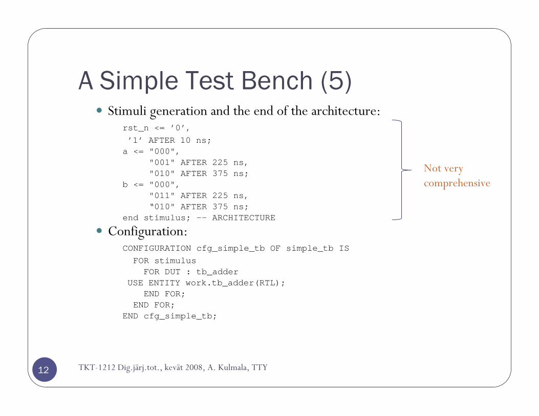
Stimuli generation and the end of the architecture:rst_n <= ’0’,’1’ AFTER 10 ns;a <= "000",
"001" AFTER 225 ns,"010" AFTER 375 ns;
b <= "000","011" AFTER 225 ns,“010" AFTER 375 ns;
end stimulus; -- ARCHITECTURE
Configuration:CONFIGURATION cfg_simple_tb OF simple_tb ISFOR stimulusFOR DUT : tb_adder
USE ENTITY work.tb_adder(RTL);END FOR;
END FOR;END cfg_simple_tb;
TKT-1212 Dig.järj.tot., kevät 2008, A. Kulmala, TTY
Not very comprehensive
A Simple Test Bench (6)
13
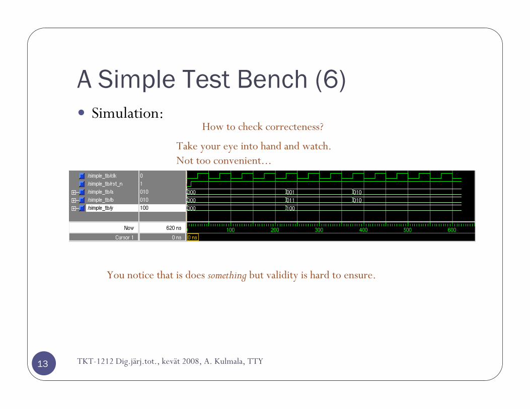
Simulation:
TKT-1212 Dig.järj.tot., kevät 2008, A. Kulmala, TTY
You notice that is does something but validity is hard to ensure.
How to check correcteness?
Take your eye into hand and watch.Not too convenient...
VHDL delay modeling
TKT-1212 Dig.järj.tot., kevät 2008, A. Kulmala, TTY14
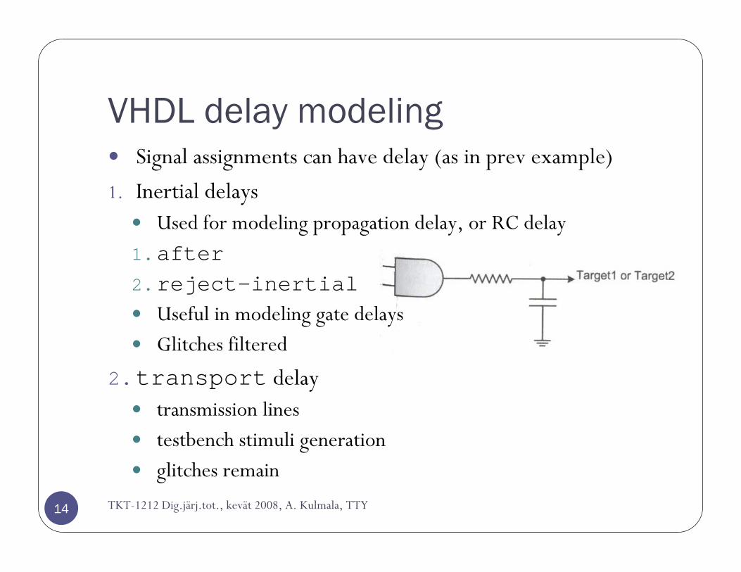
Signal assignments can have delay (as in prev example)
1. Inertial delaysUsed for modeling propagation delay, or RC delay
1.after2.reject-inertial
Useful in modeling gate delaysGlitches filtered
2.transport delaytransmission linestestbench stimuli generationglitches remain
VHDL delay modeling (2)
TKT-1212 Dig.järj.tot., kevät 2008, A. Kulmala, TTY15
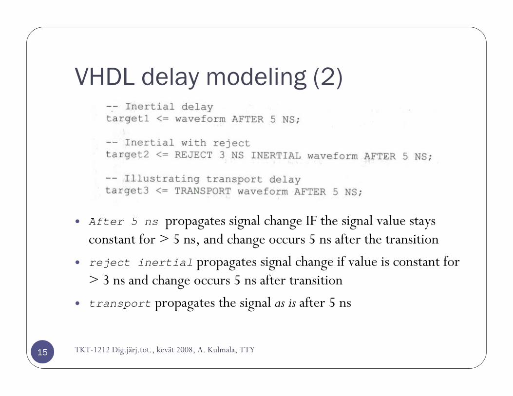
After 5 ns propagates signal change IF the signal value stays constant for > 5 ns, and change occurs 5 ns after the transition
reject inertial propagates signal change if value is constant for > 3 ns and change occurs 5 ns after transition
transport propagates the signal as is after 5 ns

VHDL delay modeling (3)
TKT-1212 Dig.järj.tot., kevät 2008, A. Kulmala, TTY16
Be careful! Behavior will be strange if the edges of the clk and signal generated this way are aligned.
More elegant test benches
Test Bench with a Separate Source
18
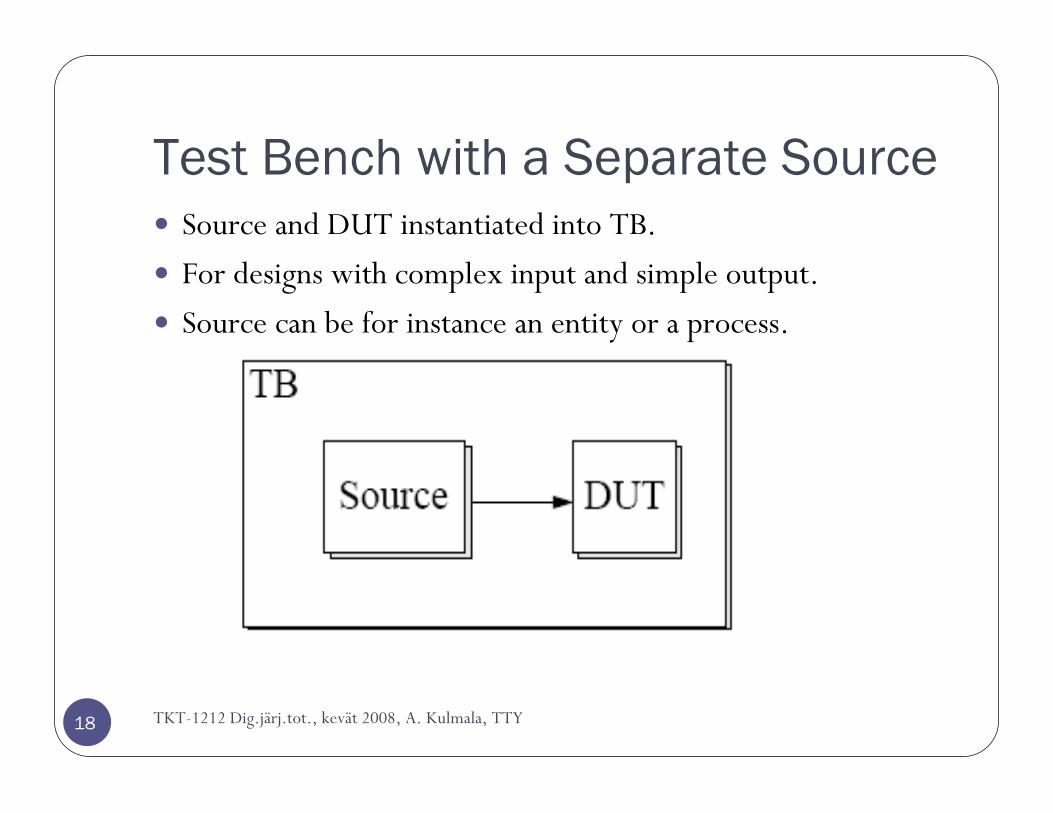
Source and DUT instantiated into TB.
For designs with complex input and simple output.
Source can be for instance an entity or a process.
TKT-1212 Dig.järj.tot., kevät 2008, A. Kulmala, TTY
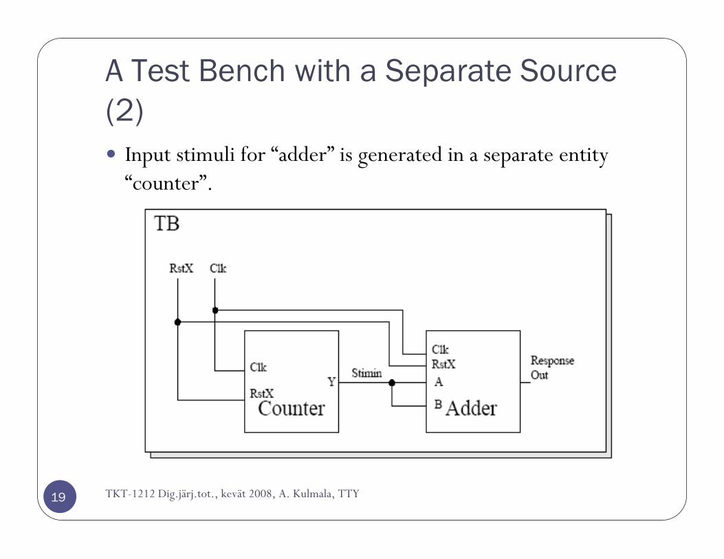
A Test Bench with a Separate Source (2)
19
Input stimuli for “adder” is generated in a separate entity“counter”.
TKT-1212 Dig.järj.tot., kevät 2008, A. Kulmala, TTY
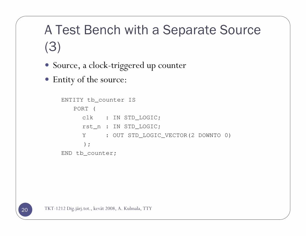
A Test Bench with a Separate Source (3)
20
Source, a clock-triggered up counter
Entity of the source:
ENTITY tb_counter ISPORT (
clk : IN STD_LOGIC;rst_n : IN STD_LOGIC;Y : OUT STD_LOGIC_VECTOR(2 DOWNTO 0));
END tb_counter;
TKT-1212 Dig.järj.tot., kevät 2008, A. Kulmala, TTY
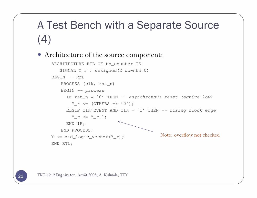
A Test Bench with a Separate Source (4)
21
Architecture of the source component:ARCHITECTURE RTL OF tb_counter IS
SIGNAL Y_r : unsigned(2 downto 0)
BEGIN -- RTL
PROCESS (clk, rst_n)
BEGIN -- process
IF rst_n = ’0’ THEN -- asynchronous reset (active low)
Y_r <= (OTHERS => ’0’);
ELSIF clk’EVENT AND clk = ’1’ THEN -- rising clock edge
Y_r <= Y_r+1;
END IF;
END PROCESS;
Y <= std_logic_vector(Y_r);
END RTL;
Note: overflow not checked
TKT-1212 Dig.järj.tot., kevät 2008, A. Kulmala, TTY
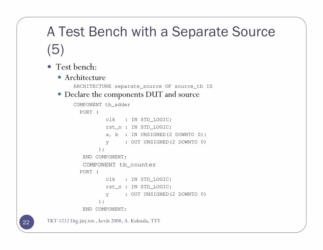
A Test Bench with a Separate Source (5)
22
Test bench:Architecture
ARCHITECTURE separate_source OF source_tb IS
Declare the components DUT and sourceCOMPONENT tb_adderPORT (
clk : IN STD_LOGIC;rst_n : IN STD_LOGIC;a, b : IN UNSIGNED(2 DOWNTO 0);y : OUT UNSIGNED(2 DOWNTO 0)
);END COMPONENT;
COMPONENT tb_counterPORT (
clk : IN STD_LOGIC;rst_n : IN STD_LOGIC;y : OUT UNSIGNED(2 DOWNTO 0)
);END COMPONENT;
TKT-1212 Dig.järj.tot., kevät 2008, A. Kulmala, TTY
A Test Bench with a Separate Source (6)
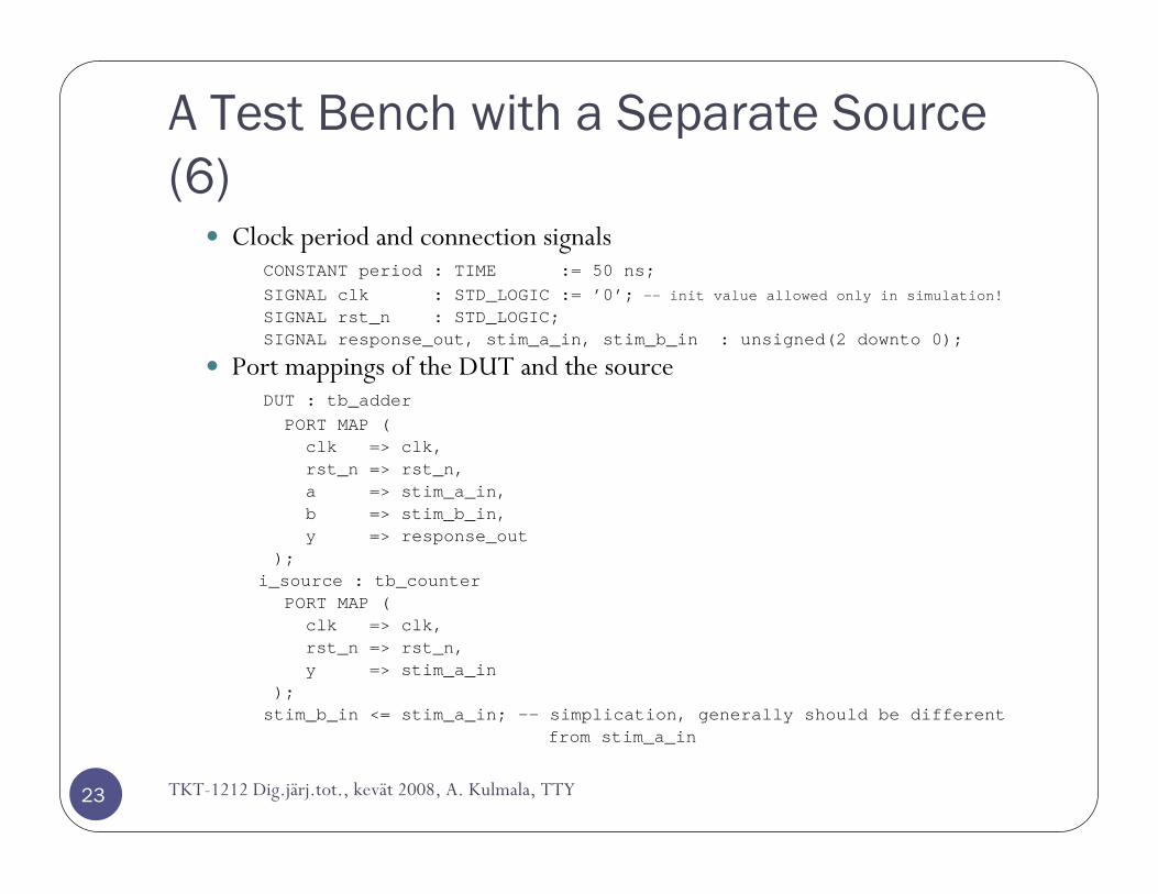
23
Clock period and connection signalsCONSTANT period : TIME := 50 ns;SIGNAL clk : STD_LOGIC := ’0’; -- init value allowed only in simulation!
SIGNAL rst_n : STD_LOGIC;SIGNAL response_out, stim_a_in, stim_b_in : unsigned(2 downto 0);
Port mappings of the DUT and the sourceDUT : tb_adder
PORT MAP (clk => clk,rst_n => rst_n,a => stim_a_in,b => stim_b_in,y => response_out
);i_source : tb_counter
PORT MAP (clk => clk,rst_n => rst_n,y => stim_a_in
);stim_b_in <= stim_a_in; -- simplication, generally should be different
from stim_a_in
TKT-1212 Dig.järj.tot., kevät 2008, A. Kulmala, TTY
A Test Bench with a Separate Source (7)
24
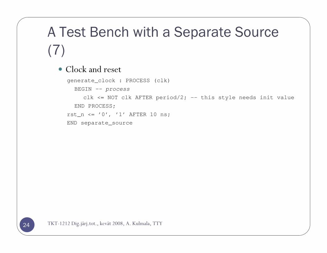
Clock and resetgenerate_clock : PROCESS (clk)
BEGIN -- process
clk <= NOT clk AFTER period/2; -- this style needs init value
END PROCESS;
rst_n <= ’0’, ’1’ AFTER 10 ns;
END separate_source
TKT-1212 Dig.järj.tot., kevät 2008, A. Kulmala, TTY
A Test Bench with a Separate Source (8)
25
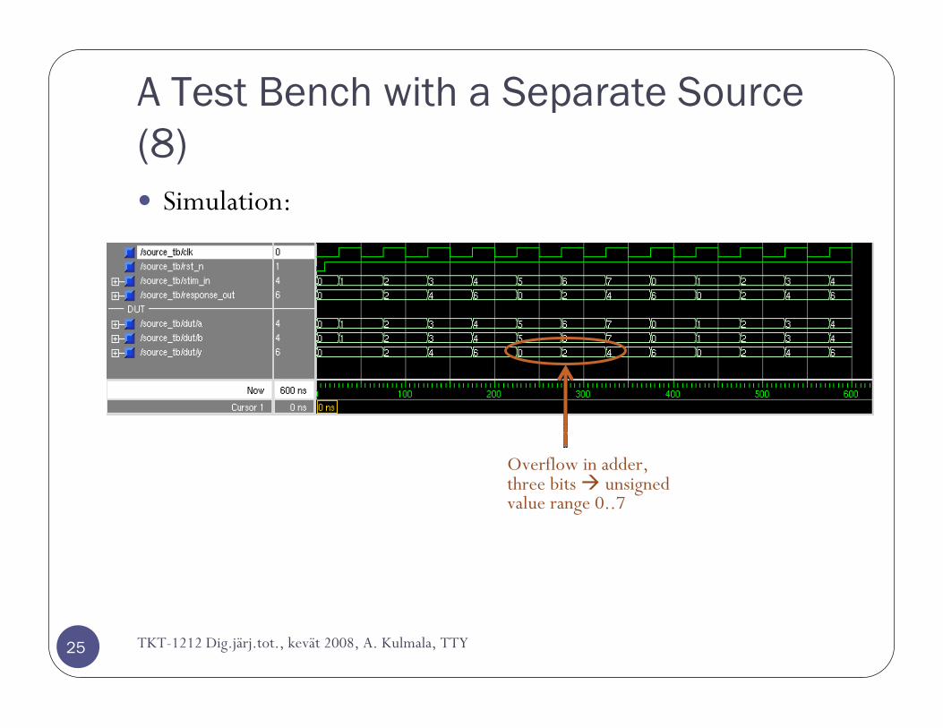
Simulation:
TKT-1212 Dig.järj.tot., kevät 2008, A. Kulmala, TTY
Overflow in adder, three bits unsigned value range 0..7

Response handling

Test Bench with a Separate Source and Sink
27
Both the stimulus source and the sink are separate instances.
Complex source and sink without response-source interaction.
TKT-1212 Dig.järj.tot., kevät 2008, A. Kulmala, TTY
stimulus response

Smart Test Bench
28
Circuit’s response affects further stimulus.
TKT-1212 Dig.järj.tot., kevät 2008, A. Kulmala, TTY
Test Bench with Text-IO
29
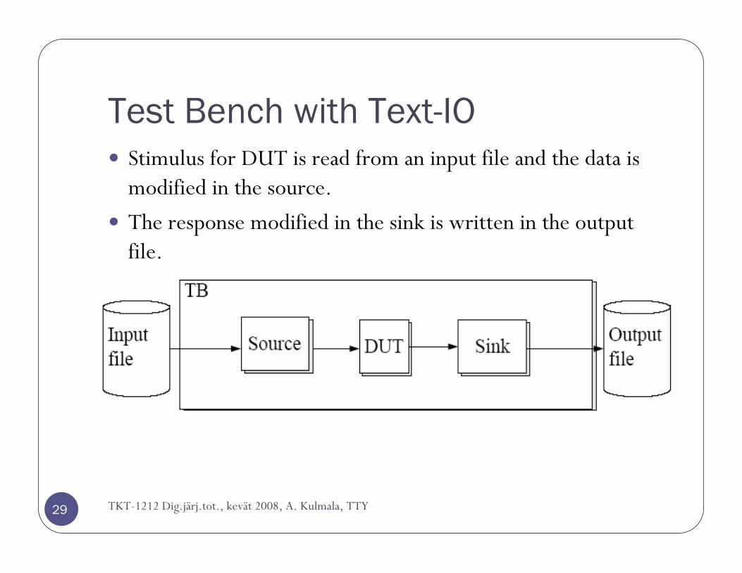
Stimulus for DUT is read from an input file and the data is modified in the source.
The response modified in the sink is written in the output file.
TKT-1212 Dig.järj.tot., kevät 2008, A. Kulmala, TTY
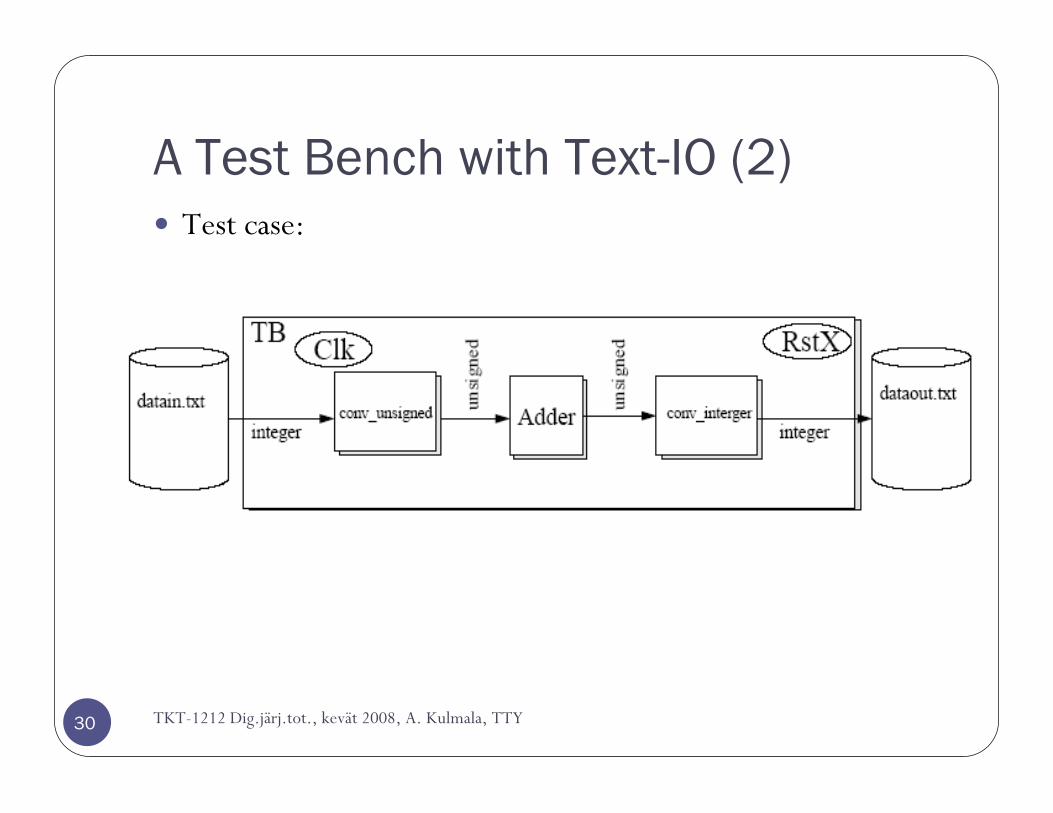
A Test Bench with Text-IO (2)
30
Test case:
TKT-1212 Dig.järj.tot., kevät 2008, A. Kulmala, TTY
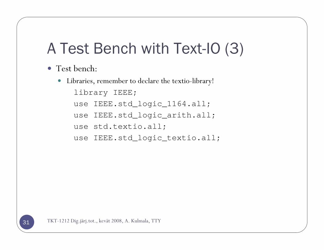
A Test Bench with Text-IO (3)
31
Test bench:Libraries, remember to declare the textio-library!
library IEEE;use IEEE.std_logic_1164.all;use IEEE.std_logic_arith.all;use std.textio.all;use IEEE.std_logic_textio.all;
TKT-1212 Dig.järj.tot., kevät 2008, A. Kulmala, TTY
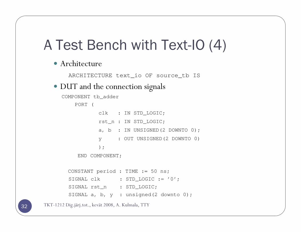
A Test Bench with Text-IO (4)
32
ArchitectureARCHITECTURE text_io OF source_tb IS
DUT and the connection signalsCOMPONENT tb_adder
PORT (
clk : IN STD_LOGIC;
rst_n : IN STD_LOGIC;
a, b : IN UNSIGNED(2 DOWNTO 0);
y : OUT UNSIGNED(2 DOWNTO 0)
);
END COMPONENT;
CONSTANT period : TIME := 50 ns;
SIGNAL clk : STD_LOGIC := ’0’;
SIGNAL rst_n : STD_LOGIC;
SIGNAL a, b, y : unsigned(2 downto 0);
TKT-1212 Dig.järj.tot., kevät 2008, A. Kulmala, TTY
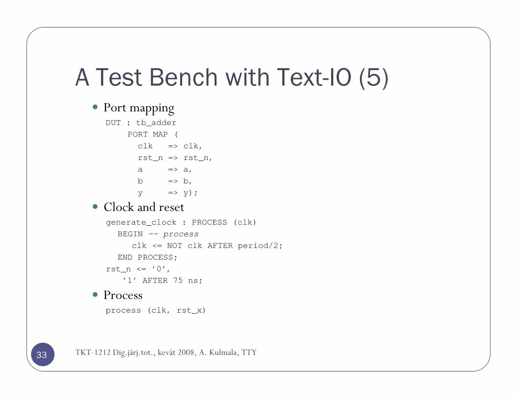
A Test Bench with Text-IO (5)
33
Port mappingDUT : tb_adder
PORT MAP (clk => clk,rst_n => rst_n,a => a,b => b,y => y);
Clock and resetgenerate_clock : PROCESS (clk)
BEGIN -- processclk <= NOT clk AFTER period/2;
END PROCESS;rst_n <= ’0’,
’1’ AFTER 75 ns;
Processprocess (clk, rst_x)
TKT-1212 Dig.järj.tot., kevät 2008, A. Kulmala, TTY

A Test Bench with Text-IO (6)
34
Declaration of the input and output filesFILE file_in : TEXT IS IN "datain.txt";FILE file_out : TEXT IS OUT "dataout.txt";File paths are relative to simulation directory (the one with modelsim.ini)
Variables for one line of the input and output filesVARIABLE line_in : LINE;VARIABLE line_out : LINE;Value of variable is updated immediately. Hence, the new value is visible on the same execution of the process (already on the next line)
Variables for the value in one lineVARIABLE input_tmp : INTEGER;VARIABLE output_tmp : INTEGER;
TKT-1212 Dig.järj.tot., kevät 2008, A. Kulmala, TTY
A Test Bench with Text-IO (7)
35
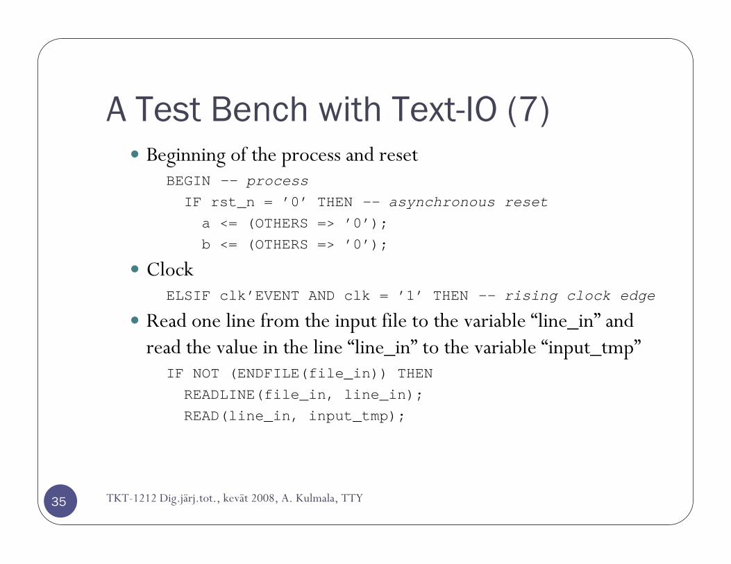
Beginning of the process and resetBEGIN -- processIF rst_n = ’0’ THEN -- asynchronous reset
a <= (OTHERS => ’0’);b <= (OTHERS => ’0’);
ClockELSIF clk’EVENT AND clk = ’1’ THEN -- rising clock edge
Read one line from the input file to the variable “line_in” and read the value in the line “line_in” to the variable “input_tmp”
IF NOT (ENDFILE(file_in)) THENREADLINE(file_in, line_in);READ(line_in, input_tmp);
TKT-1212 Dig.järj.tot., kevät 2008, A. Kulmala, TTY
A Test Bench with Text-IO (8)
36
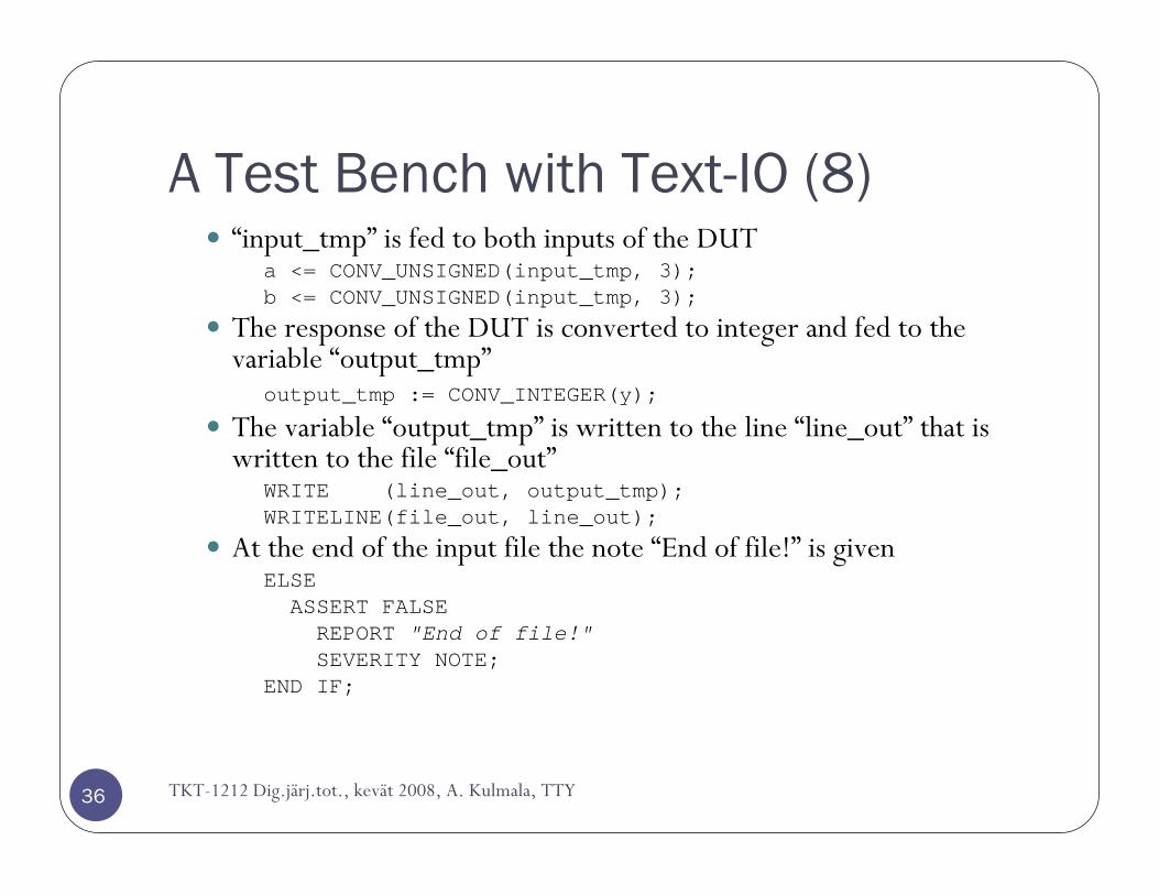
“input_tmp” is fed to both inputs of the DUTa <= CONV_UNSIGNED(input_tmp, 3);b <= CONV_UNSIGNED(input_tmp, 3);
The response of the DUT is converted to integer and fed to the variable “output_tmp”
output_tmp := CONV_INTEGER(y);
The variable “output_tmp” is written to the line “line_out” that is written to the file “file_out”
WRITE (line_out, output_tmp);WRITELINE(file_out, line_out);
At the end of the input file the note “End of file!” is givenELSEASSERT FALSEREPORT "End of file!"SEVERITY NOTE;
END IF;
TKT-1212 Dig.järj.tot., kevät 2008, A. Kulmala, TTY
A Test Bench with Text-IO (9)
37
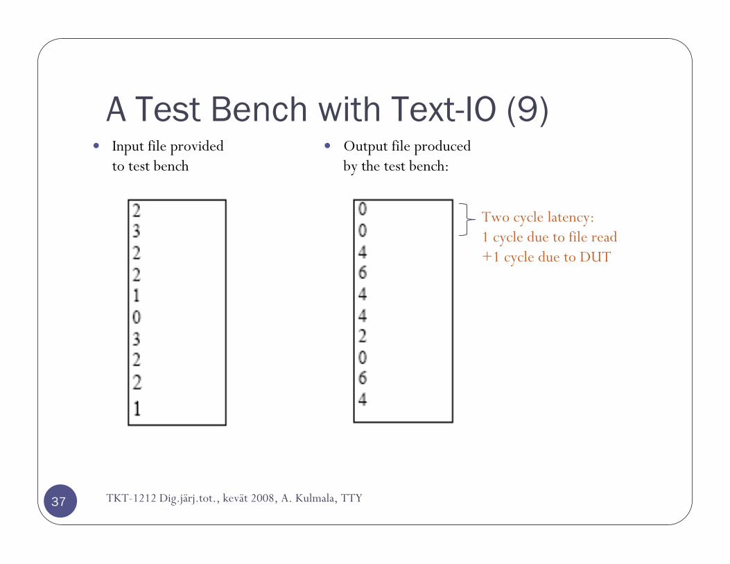
Output file produced by the test bench:
Input file provided to test bench
TKT-1212 Dig.järj.tot., kevät 2008, A. Kulmala, TTY
Two cycle latency:1 cycle due to file read+1 cycle due to DUT
A Test Bench with Text-IO (10)
38
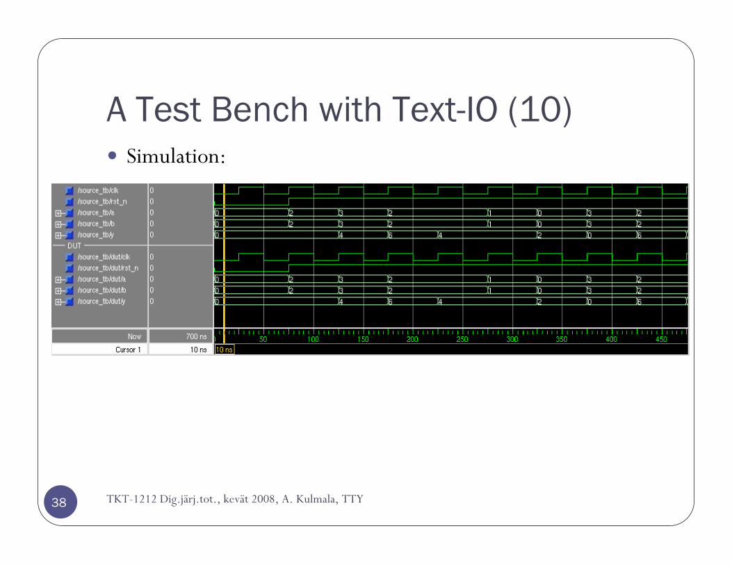
Simulation:
TKT-1212 Dig.järj.tot., kevät 2008, A. Kulmala, TTY
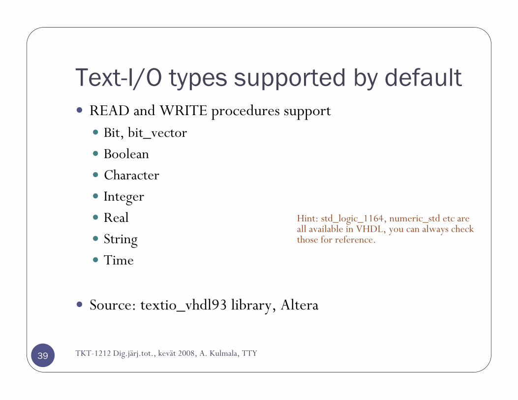
Text-I/O types supported by default
TKT-1212 Dig.järj.tot., kevät 2008, A. Kulmala, TTY39
READ and WRITE procedures supportBit, bit_vectorBooleanCharacterIntegerRealStringTime
Source: textio_vhdl93 library, Altera
Hint: std_logic_1164, numeric_std etc are all available in VHDL, you can always check those for reference.
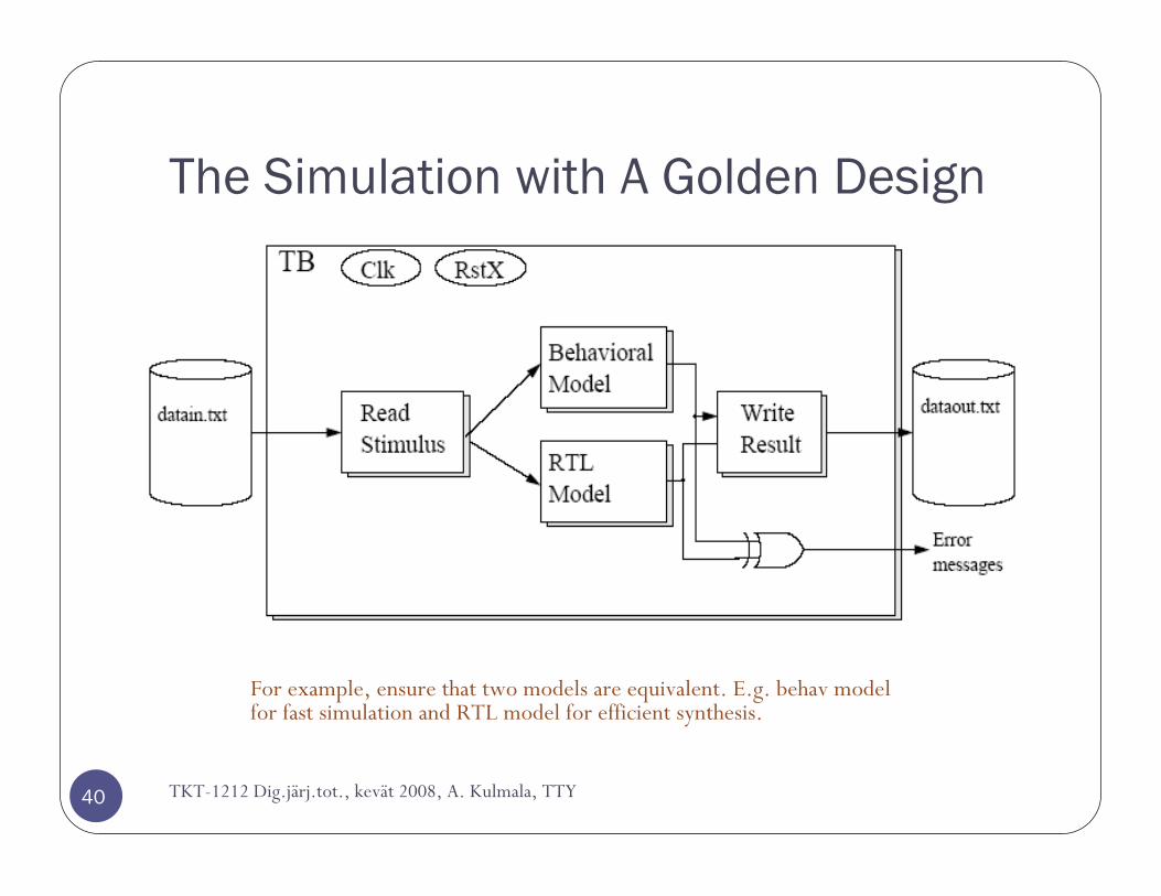
The Simulation with A Golden Design
40 TKT-1212 Dig.järj.tot., kevät 2008, A. Kulmala, TTY
For example, ensure that two models are equivalent. E.g. behav model for fast simulation and RTL model for efficient synthesis.
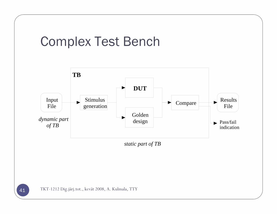
Complex Test Bench
41
DUT
Goldendesign
CompareStimulusgeneration
InputFile
ResultsFile
TB
Pass/failindication
static part of TB
dynamic partof TB
TKT-1212 Dig.järj.tot., kevät 2008, A. Kulmala, TTY
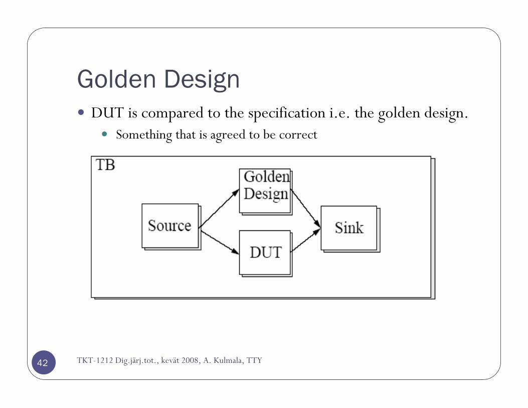
Golden Design
42
DUT is compared to the specification i.e. the golden design.Something that is agreed to be correct
TKT-1212 Dig.järj.tot., kevät 2008, A. Kulmala, TTY
VHDL TESTBENCH
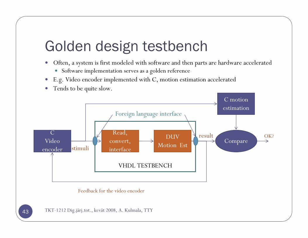
Golden design testbench
TKT-1212 Dig.järj.tot., kevät 2008, A. Kulmala, TTY43
Often, a system is first modeled with software and then parts are hardware acceleratedSoftware implementation serves as a golden reference
E.g. Video encoder implemented with C, motion estimation acceleratedTends to be quite slow.
CVideo
encoder
Read, convert, interfacestimuli
DUVMotion Est
C motion estimation
Compareresult
Feedback for the video encoder
OK?
Foreign language interface
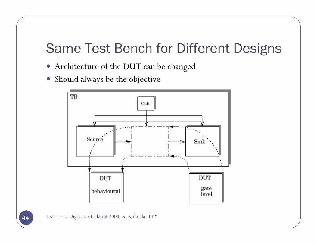
Same Test Bench for Different Designs
44
Architecture of the DUT can be changedShould always be the objective
TKT-1212 Dig.järj.tot., kevät 2008, A. Kulmala, TTY

Autonomous test bench
45
Does not need input file stimulusDetermines the right result ”on-the-fly”Very good for checking if simple changes or optimizations broke the designNote that some (pseudo-)randomization on the stimuli must be done in order to make sure that the corner cases are covered
Check the code, statement, and branch coverages!
DUT
Result calculation
CompareStimulus generation
TB
Pass/failindication
static part of TB
Stimulus configuration
TKT-1212 Dig.järj.tot., kevät 2008, A. Kulmala, TTY
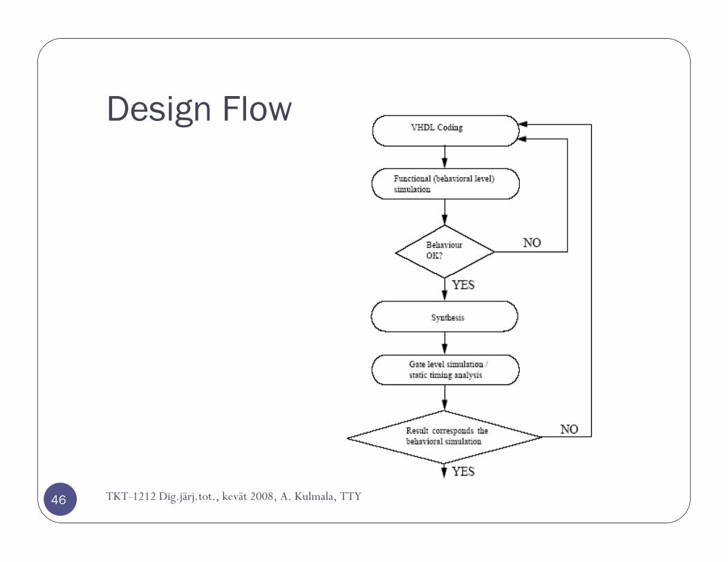
Design Flow
46 TKT-1212 Dig.järj.tot., kevät 2008, A. Kulmala, TTY

Example and conclusions
Example: verifying an interconnection
48
DUV, the interconnectionDelivers data from a single source to destination so that
1. data remain in-order2. data are error-free 3. with finite latencyNote that the only the transferred data integrity is important, not what it representsThe testbench can be deferred to a few assertions
a) Data A arrives at destinationb) Data B does not arrive before A, if A was sent before itc) Data does not change (or duplicate)When checking these assertions, you also implicitely verify the correctness of the interface!
i.e. read-during-write, write to full buffer, write with an erroneous command etc.All of these can be fairly simply accomplished with an automatic test bench requiring no external filesSeparate the stimuli and verification
TKT-1212 Dig.järj.tot., kevät 2008, A. Kulmala, TTY
Test AgentTest Agent
Sender
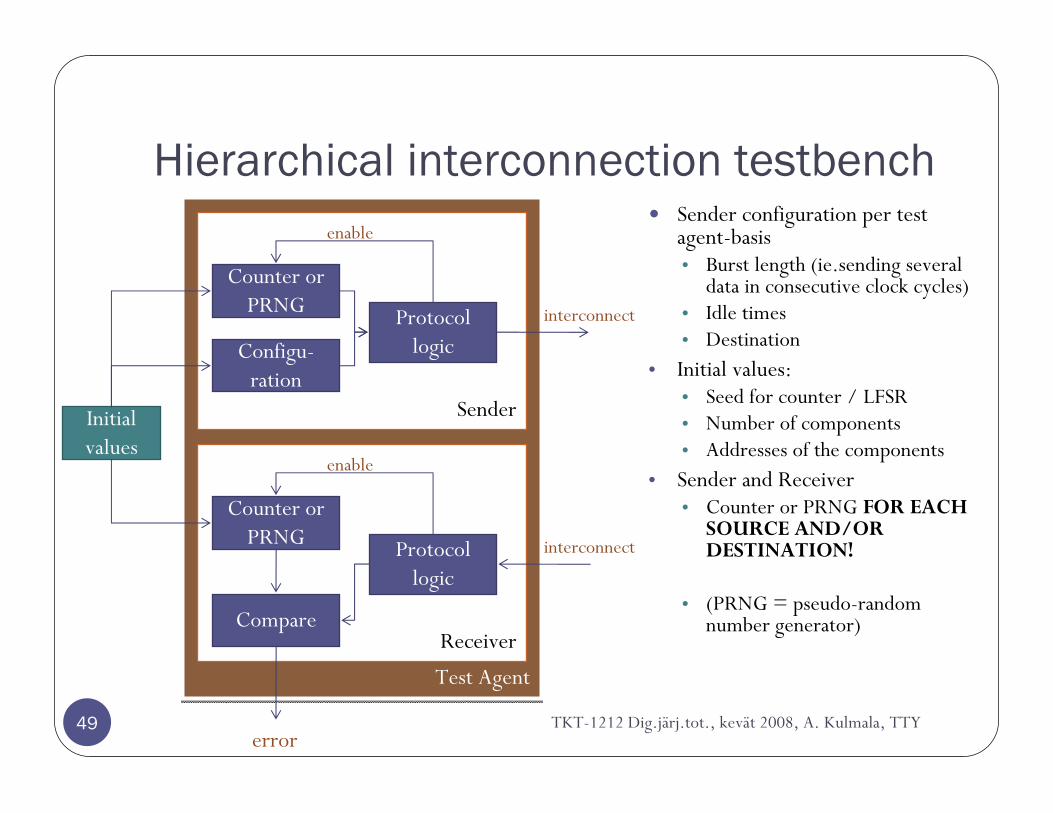
Hierarchical interconnection testbench
49
Sender configuration per test agent-basis• Burst length (ie.sending several
data in consecutive clock cycles)• Idle times• Destination
• Initial values:• Seed for counter / LFSR• Number of components• Addresses of the components
• Sender and Receiver• Counter or PRNG FOR EACH
SOURCE AND/OR DESTINATION!
• (PRNG = pseudo-random number generator)
Counter or PRNG Protocol
logicConfigu-ration
enable
interconnect
Receiver
Counter or PRNG Protocol
logic
Compare
enable
interconnect
Initial values
errorTKT-1212 Dig.järj.tot., kevät 2008, A. Kulmala, TTY

The testbench
50
Expandable to very large configurations
Test AgentTest
Agent
Test AgentTest
Agent
Test AgentTest
Agent
Test AgentTest
Agent
Test Agent
Test Agent
Test AgentTest
AgentTest
AgentTest
AgentTest
AgentTest
Agent
Test AgentTest
AgentTest
AgentTest
AgentTest
AgentTest
AgentTest
AgentTest
Agent
INTERCONNECTION
TKT-1212 Dig.järj.tot., kevät 2008, A. Kulmala, TTY

What is the interconnection?
51
The interconnection topology does not matter since we did not take that into account in the assumptions, only the functionality of the interconnectiona) Data A arrives at destinationb) Data B does not arrive before A, if A was sent before itc) Data does not change (or duplicate)
a)Typical: Single shared bus
c) Meshd) Butterfly
b) Hierarchical octagon
SourceDestination
TKT-1212 Dig.järj.tot., kevät 2008, A. Kulmala, TTY
Autonomous and complex test benches
52
Always a preferred choiceWell designed, resusable testbench pays back
Use modular designInput (stimuli) separated from output (check) blocks in codeAll the testbenches should be designed so that they automatically check for errors
No manual comparison in any stageCode coverage must be high
However, high code coverage does not imply that the TB is all-inclusive, but it is required for that!Autonomous test benches must include long runs and random patterns to make sure that corner cases are checked
Designing the test benches in a synchronous manner makes sure that the delta delays do not mess things up
Synchronous test bench also works as the real environment wouldMore on the delta delay on next lecture about simulators
TKT-1212 Dig.järj.tot., kevät 2008, A. Kulmala, TTY
Example VHD:
53
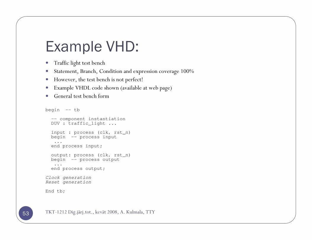
Traffic light test benchStatement, Branch, Condition and expression coverage 100%However, the test bench is not perfect!Example VHDL code shown (available at web page)General test bench form
begin -- tb
-- component instantiationDUV : traffic_light ...
input : process (clk, rst_n)begin -- process input...end process input;
output: process (clk, rst_n)begin -- process output...end process output;
Clock generationReset generation
End tb;
TKT-1212 Dig.järj.tot., kevät 2008, A. Kulmala, TTY

Synthesizable testbenches
TKT-1212 Dig.järj.tot., kevät 2008, A. Kulmala, TTY54
Synchronous, synthesizable test benches are a good practice if e.g. the design includes clock domain crossings
Can be synthesized to a FPGA and tested in a real environmentRun-time error checking facilities to a real product may be extracted from the test bench easilyThen, assertion should be written this way:
If (a > b) thenassert false ”error” …error_out(0) <= ’1’;
End if;
Or one can make own assertions for simulation and synthesis, e.g.Assert_gen(cond, level, error_sig);
In simulation, regular assertion, in synthesis, assigns to error_sig
General guidelines
55
Every entity you design has an own test bench.
Automatic verification and result checkInput generated internally or from fileOutput checked automaticallyThe less external files we rely on, the easier is the usage (scripts)
Somebody else may also be using your code! e.g.
”Vsim my_tb; run 10ms; ”tests ok””
”Make verify”
Timeout counters detect if the design does not respond at all!
Do not rely that the designer checks the wavesTKT-1212 Dig.järj.tot., kevät 2008, A. Kulmala, TTY

The end.
Questions?
56 TKT-1212 Dig.järj.tot., kevät 2008, A. Kulmala, TTY