Lectures 5: Seq. and comb. logic, statements, generics · Department of Computer Systems Lectures...
55
Department of Computer Systems Lectures 5: Seq. and comb. logic, statements, generics TKT-1212 Digitaalijärjestelmien toteutus Erno Salminen Tampere university of technology Spring 2013 D Q Comb. logic foo_r a_in b_in c_in n 1 n n Seq. logic
Transcript of Lectures 5: Seq. and comb. logic, statements, generics · Department of Computer Systems Lectures...

Department of Computer Systems
Lectures 5: Seq. and comb. logic, statements, genericsTKT-1212 Digitaalijärjestelmien toteutusErno SalminenTampere university of technologySpring 2013
D QComb. logic
foo_ra_inb_in
c_in
n
1
n
n
Seq. logic

#2/55 Department of Computer Systems
AcknowledgementsProf. Pong . P. Chu provided ”official” slides
for the book which is gratefully aknowledged See also: http://academic.csuohio.edu/chu_p/
Most slides were made by Ari Kulmala and other previous lecturers (Teemu Pitkänen,
Konsta Punkka, Mikko Alho…)
Erno Salminen, TUT, 2013
#3/55 Department of Computer Systems
ContentsComb and seq. logic from VHDLStatements of VHDLCommon pitfalls
Erno Salminen, TUT, 2013
#4/55 Department of Computer Systems
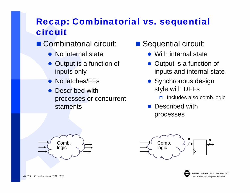
Recap: Combinatorial vs. sequential circuit Combinatorial circuit:
No internal state Output is a function of
inputs only No latches/FFs Described with
processes or concurrentstaments
Sequential circuit: With internal state Output is a function of
inputs and internal state Synchronous design
style with DFFs Includes also comb.logic
Described withprocesses
Comb. logic
Comb. logic
n n
Erno Salminen, TUT, 2013
#5/55 Department of Computer Systems
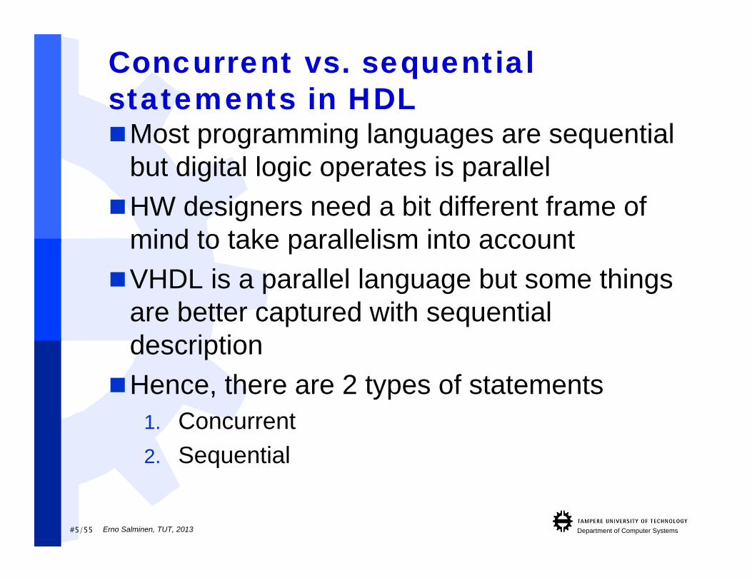
Concurrent vs. sequential statements in HDLMost programming languages are sequential
but digital logic operates is parallelHW designers need a bit different frame of
mind to take parallelism into accountVHDL is a parallel language but some things
are better captured with sequentialdescriptionHence, there are 2 types of statements
1. Concurrent2. Sequential
Erno Salminen, TUT, 2013
#6/55 Department of Computer Systems
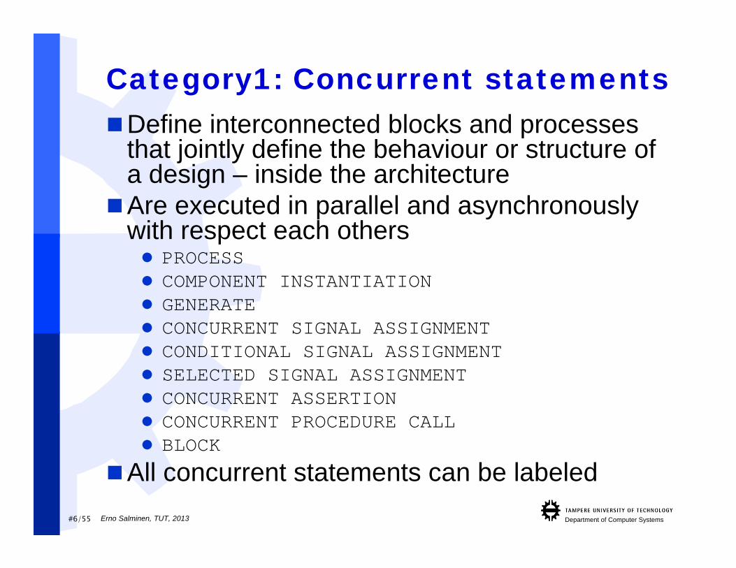
Category1: Concurrent statementsDefine interconnected blocks and processes
that jointly define the behaviour or structure of a design – inside the architecture
Are executed in parallel and asynchronously with respect each others PROCESS COMPONENT INSTANTIATION GENERATE CONCURRENT SIGNAL ASSIGNMENT CONDITIONAL SIGNAL ASSIGNMENT SELECTED SIGNAL ASSIGNMENT CONCURRENT ASSERTION CONCURRENT PROCEDURE CALL BLOCK
All concurrent statements can be labeledErno Salminen, TUT, 2013
#7/55 Department of Computer Systems
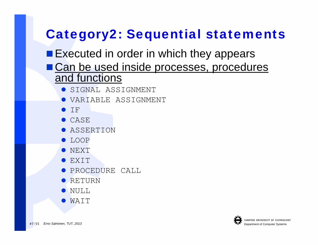
Category2: Sequential statementsExecuted in order in which they appearsCan be used inside processes, procedures
and functions SIGNAL ASSIGNMENT VARIABLE ASSIGNMENT IF CASE ASSERTION LOOP NEXT EXIT PROCEDURE CALL RETURN NULL WAIT
Erno Salminen, TUT, 2013
#8/55 Department of Computer Systems
Sequential Statements vs. Logic
Sequential VHDL statements do not necessarily represent synchronous sequential digital logic circuits They can describe both combinatorial and
synchronous logic circuitsModeling combinatorial logic with sequential
statements: Sensivity list of process statements must contain
all inputs used in VHDL statements Conditional & selected signal assignments (also
if and case statements) most cover all possible branches (to avoid inferring unintentional latches)
Erno Salminen, TUT, 2013

#9/55 Department of Computer Systems
Seq. statements: IF Like in conventional programming languages
Priority encoded (if tested first, then elsif, then else).IF condition THEN
sequence of statements[ ELSIF condition2
sequence of statements ][ ELSE
sequence of statements ]END IF;
Example of incrementing and clipping values within allowed range:IF a > upper_limit_c THEN
a <= upper_limit_c;ELSIF a < lower_limit_c
a <= lower_limit_c;ELSE
a <= a+1;END IF;
Inside processes, procedures and functions only
Erno Salminen, TUT, 2013
#10/55 Department of Computer Systems
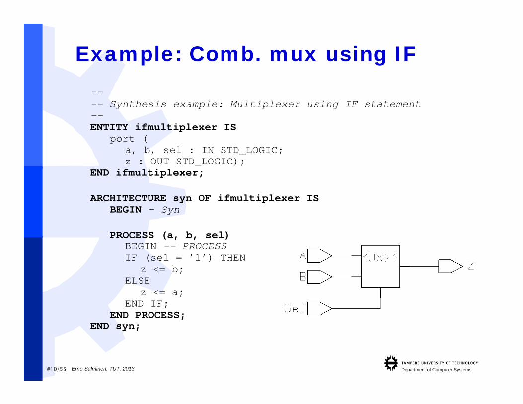
Example: Comb. mux using IF---- Synthesis example: Multiplexer using IF statement--ENTITY ifmultiplexer IS
port (a, b, sel : IN STD_LOGIC;z : OUT STD_LOGIC);
END ifmultiplexer;
ARCHITECTURE syn OF ifmultiplexer ISBEGIN – Syn
PROCESS (a, b, sel)BEGIN -- PROCESSIF (sel = ’1’) THEN
z <= b;ELSE
z <= a;END IF;
END PROCESS;END syn;
Erno Salminen, TUT, 2013

#11/55 Department of Computer Systems
Sequential Statements vs. Sequential Logic The two basic types of synchronous
elements are1. D-type latch (level sensitive memory cell)2. D-type flip-flop (edge-triggered memory cell)
The main disadvantage of latches(instead of flip-flops) is that static timinganalysis (STA) of synthesized circuits canbe very complex Do not use latches! => Inferred latches
indicate very likely a bug They also complicate manufacturing tests
D Q
clk
D Q
ena
Erno Salminen, TUT, 2013
#12/55 Department of Computer Systems
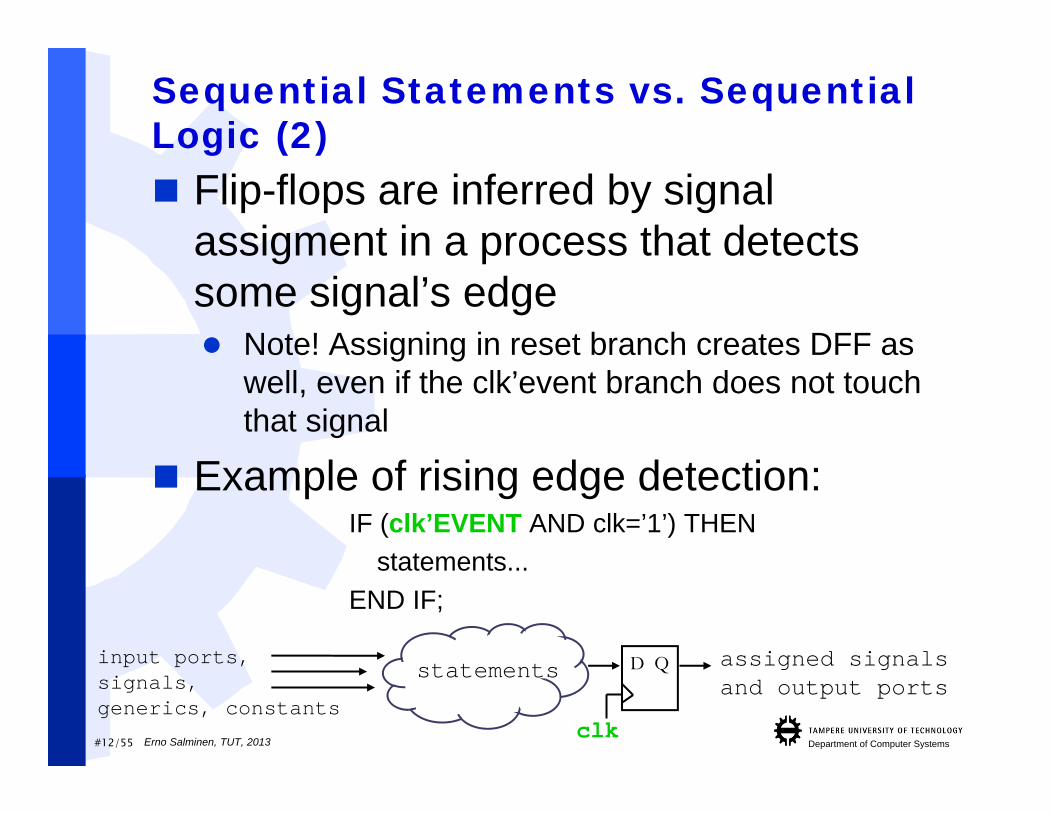
Sequential Statements vs. Sequential Logic (2) Flip-flops are inferred by signal
assigment in a process that detectssome signal’s edge Note! Assigning in reset branch creates DFF as
well, even if the clk’event branch does not touchthat signal
Example of rising edge detection:IF (clk’EVENT AND clk=’1’) THEN
statements...END IF;
D Qstatementsinput ports,signals,generics, constants
clk
assigned signalsand output ports
Erno Salminen, TUT, 2013
#13/55 Department of Computer Systems
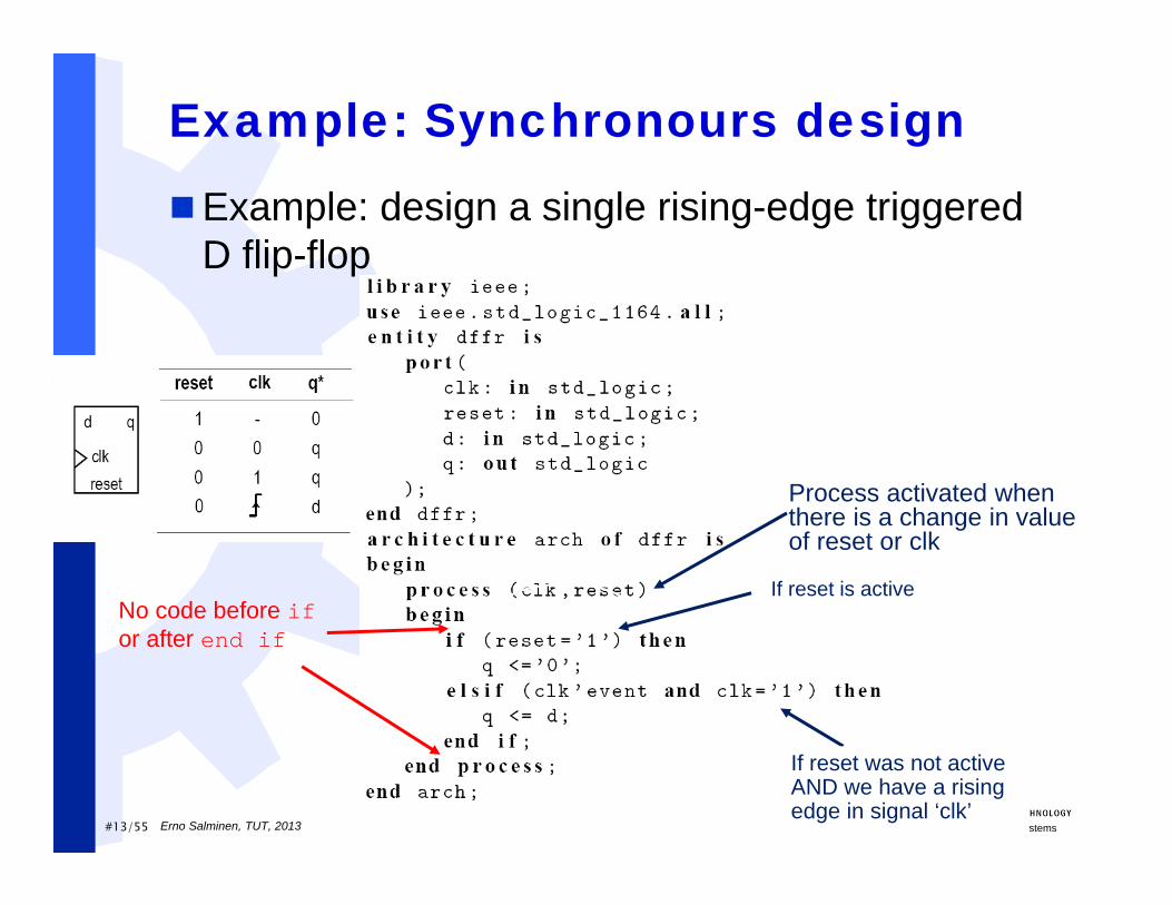
Example: Synchronours design
Example: design a single rising-edge triggered D flip-flop
If reset is active
If reset was not active AND we have a rising edge in signal ‘clk’
Process activated when there is a change in value of reset or clk
No code before ifor after end if
Erno Salminen, TUT, 2013
#14/55 Department of Computer Systems
Designing Synchronous Circuits All signals and ports that are assigned a value in process
containing[ELS]IF (clk’EVENT AND clk=’1’) THENare implemented as registers! Note that a register consists of several flip-flops
This is because these assignments take place only at clockedge This is exactly how the flip-flops work: they load the input
value on clock edge Explicit usage of flip-flop components is not recommended Many signal types can infer registers. Integers become
registers (32b) as well as std_logic_vectors and own definedtypes. A flip-flop is instantiated for each bit Integer ranges should be defined
Erno Salminen, TUT, 2013

#15/55 Department of Computer Systems
Designing synchronous circuits (2)
Remember the concept of RTL designWith VHDL synchronous design style, this is
actually just what you do Define what happens before a register and
where that data goes
D QComb. logic
...ELSIF clk'event AND clk = '1' THEN -- rising clock edge
result_r <= (a_in XOR b_in) + c_in;END IF;... Do this operation and move the
result to result register
result_ra_inb_inc_in
Inputs may comefrom registers orother comb logic, but example code
does not show where
The code shows that result_r is a register, postfix _r is meant for human reader
clkErno Salminen, TUT, 2013
#16/55 Department of Computer Systems
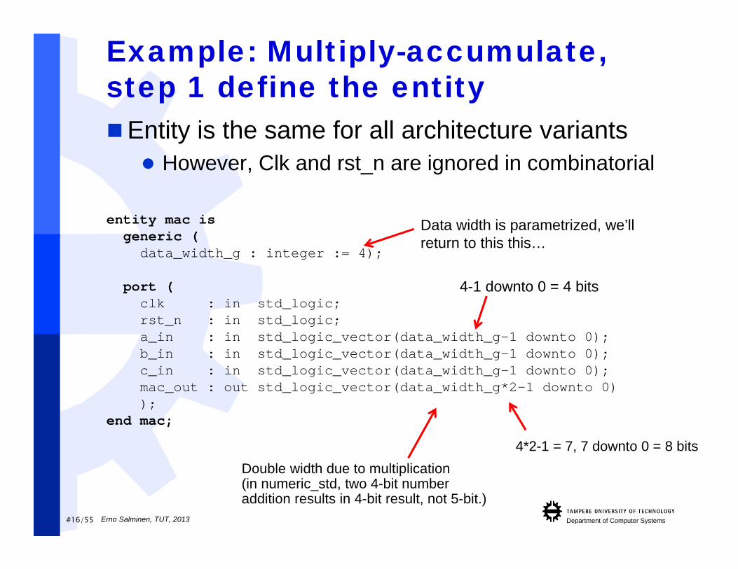
Example: Multiply-accumulate, step 1 define the entityEntity is the same for all architecture variants
However, Clk and rst_n are ignored in combinatorial
entity mac isgeneric (data_width_g : integer := 4);
port (clk : in std_logic;rst_n : in std_logic;a_in : in std_logic_vector(data_width_g-1 downto 0);b_in : in std_logic_vector(data_width_g-1 downto 0);c_in : in std_logic_vector(data_width_g-1 downto 0);mac_out : out std_logic_vector(data_width_g*2-1 downto 0));
end mac;
Double width due to multiplication(in numeric_std, two 4-bit number addition results in 4-bit result, not 5-bit.)
4-1 downto 0 = 4 bits
4*2-1 = 7, 7 downto 0 = 8 bits
Data width is parametrized, we’llreturn to this this…
Erno Salminen, TUT, 2013

#17/55 Department of Computer Systems
MAC: 3 possible architectures1) Combinatorial circuit:
*+
A_inB_in
C_inMac_out
*+
A_inB_in
C_inMac_out
D Q
*+
A_inB_in
C_in
Mac_outD Q
D Q
D Q
2) Synchronous circuit:
3) Pipelined synchronous circuit:
Erno Salminen, TUT, 2013
#18/55 Department of Computer Systems
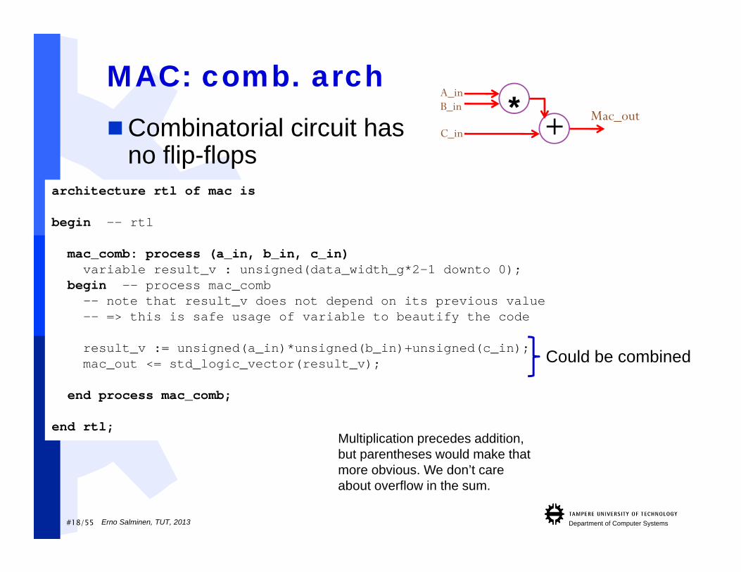
MAC: comb. archCombinatorial circuit has
no flip-flopsarchitecture rtl of mac is
begin -- rtl
mac_comb: process (a_in, b_in, c_in)variable result_v : unsigned(data_width_g*2-1 downto 0);
begin -- process mac_comb-- note that result_v does not depend on its previous value-- => this is safe usage of variable to beautify the code
result_v := unsigned(a_in)*unsigned(b_in)+unsigned(c_in);mac_out <= std_logic_vector(result_v);
end process mac_comb;
end rtl;
Could be combined
*+
A_inB_in
C_inMac_out
Multiplication precedes addition, but parentheses would make thatmore obvious. We don’t careabout overflow in the sum.
Erno Salminen, TUT, 2013

#19/55 Department of Computer Systems
MAC: synch. arch Synchronous circuit with
single output flip-floparchitecture rtl of mac is
begin -- rtl
mac_sync : process (clk, rst_n)variable result_v : unsigned(data_width_g*2-1 downto 0);
begin -- process mac_combif rst_n = '0' then -- asynchronous reset (active low)mac_out <= (others => '0');
elsif clk'event and clk = '1' then -- rising clock edgeresult_v := unsigned(a_in)*unsigned(b_in)+unsigned(c_in);mac_out <= std_logic_vector(result_v);
end if;end process mac_sync;
end rtl;
Calculation inside the ”clock region”
A register is generated for mac_outsince:•It is a signal (port out)•It is assigned a value within the clock region
Result_v is not implemented as register since • it is a variable that does not depend on its previous value
*+
A_inB_in
C_inMac_out
D Q
Erno Salminen, TUT, 2013
#20/55 Department of Computer Systems
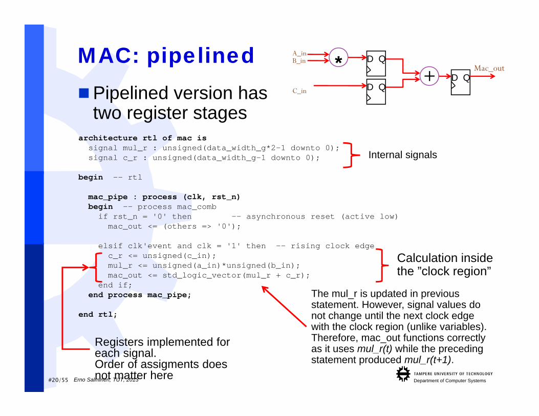
MAC: pipelinedPipelined version has
two register stagesarchitecture rtl of mac is
signal mul_r : unsigned(data_width_g*2-1 downto 0);signal c_r : unsigned(data_width_g-1 downto 0);
begin -- rtl
mac_pipe : process (clk, rst_n)begin -- process mac_comb
if rst_n = '0' then -- asynchronous reset (active low)mac_out <= (others => '0');
elsif clk'event and clk = '1' then -- rising clock edgec_r <= unsigned(c_in);mul_r <= unsigned(a_in)*unsigned(b_in);mac_out <= std_logic_vector(mul_r + c_r);
end if;end process mac_pipe;
end rtl;
Calculation inside the ”clock region”
Registers implemented for each signal. Order of assigments doesnot matter here
The mul_r is updated in previous statement. However, signal values do not change until the next clock edge with the clock region (unlike variables).Therefore, mac_out functions correctly as it uses mul_r(t) while the preceding statement produced mul_r(t+1).
*+
A_inB_in
C_in
Mac_outD Q
D Q
D Q
Internal signals
Erno Salminen, TUT, 2013

#21/55 Department of Computer Systems
A_inB_in
C_in
MAC: second pipelined version 4) Pipelined Synchronous circuit without out-register:
*+ Mac_out
D Q
D Q
architecture rtl of mac issignal mul_r : unsigned(data_width_g*2-1 downto 0);signal c_r : unsigned(data_width_g-1 downto 0);
begin -- rtl
mac_pipe : process (clk, rst_n)begin -- process mac_comb
if rst_n = '0' then-- Note that intermediate pipeline registers do -- not have to be nullified under resetc_r <= (others => '0');mul_r <= (others => '0');
elsif clk'event and clk = '1’c_r <= unsigned(c_in);mul_r <= unsigned(a_in)*unsigned(b_in);
end if;end process mac_pipe;
mac_out <= std_logic_vector(mul_r + c_r);
end rtl;
Mac_out moved out of the clockregion causes that no registergenerated for it but just a wirecoming from an adder
Continous signal assignment to mac_out so it must not be reset
Erno Salminen, TUT, 2013
#22/55 Department of Computer Systems
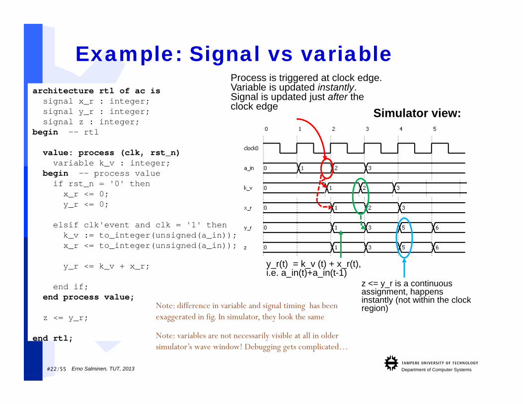
architecture rtl of ac issignal x_r : integer;signal y_r : integer;signal z : integer;
begin -- rtl
value: process (clk, rst_n)variable k_v : integer;
begin -- process valueif rst_n = '0' thenx_r <= 0;y_r <= 0;
elsif clk'event and clk = '1' thenk_v := to_integer(unsigned(a_in));x_r <= to_integer(unsigned(a_in));
y_r <= k_v + x_r;
end if;end process value;
z <= y_r;
end rtl;
Example: Signal vs variableProcess is triggered at clock edge.Variable is updated instantly.Signal is updated just after the clock edge
z <= y_r is a continuous assignment, happens instantly (not within the clock region)
y_r(t) = k_v (t) + x_r(t), i.e. a_in(t)+a_in(t-1)
Note: variables are not necessarily visible at all in older simulator’s wave window! Debugging gets complicated…
Simulator view:
Erno Salminen, TUT, 2013
Note: difference in variable and signal timing has been exaggerated in fig. In simulator, they look the same
#23/55 Department of Computer Systems
architecture rtl of ac issignal x_r : integer;signal y_r : integer;signal z : integer;
begin -- rtl
value: process (clk, rst_n)variable k_v : integer;
begin -- process valueif rst_n = '0' thenx_r <= 0;y_r <= 0;
elsif clk'event and clk = '1' thenk_v := to_integer(unsigned(a_in));x_r <= to_integer(unsigned(a_in));
y_r <= k_v + x_r;
end if;end process value;
z <= y_r;
end rtl;
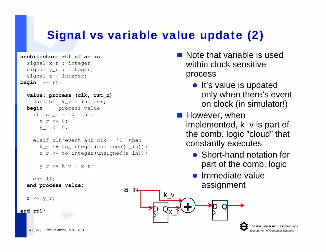
Signal vs variable value update (2) Note that variable is used
within clock sensitiveprocess It’s value is updated
only when there’s eventon clock (in simulator!)
However, whenimplemented, k_v is part of the comb. logic ”cloud” thatconstantly executes Short-hand notation for
part of the comb. logic Immediate value
assignment
+ D QD Q
a_ink_v
x_r
Erno Salminen, TUT, 2013
#24/55 Department of Computer Systems
architecture rtl of ac issignal x_r : integer;signal y_r : integer;signal z : integer;
begin -- rtl
value: process (clk, rst_n)variable k_v : integer;
begin -- process valueif rst_n = '0' thenx_r <= 0;y_r <= 0;
elsif clk'event and clk = '1' thenk_v := to_integer(unsigned(a_in));x_r <= to_integer(unsigned(a_in));
y_r <= k_v + x_r;
end if;end process value;
z <= y_r;
end rtl;
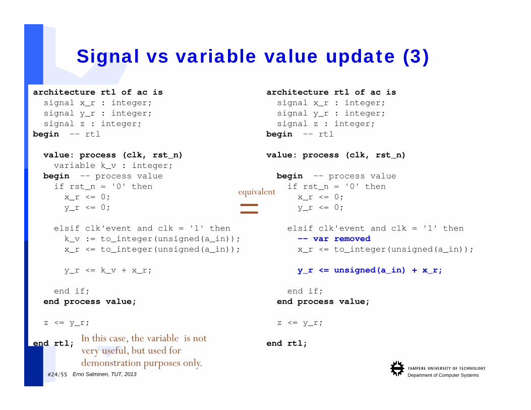
Signal vs variable value update (3)architecture rtl of ac issignal x_r : integer;signal y_r : integer;signal z : integer;
begin -- rtl
value: process (clk, rst_n)
begin -- process valueif rst_n = '0' thenx_r <= 0;y_r <= 0;
elsif clk'event and clk = '1' then-- var removedx_r <= to_integer(unsigned(a_in));
y_r <= unsigned(a_in) + x_r;
end if;end process value;
z <= y_r;
end rtl;
equivalent
=
In this case, the variable is notvery useful, but used for demonstration purposes only.
Erno Salminen, TUT, 2013
#25/55 Department of Computer Systems
architecture rtl of ac issignal x_r : integer;signal y_r : integer;signal z : integer;
begin -- rtl
value: process (clk, rst_n)variable k_v : integer;
begin -- process valueif rst_n = '0' thenx_r <= 0;y_r <= 0;
elsif clk'event and clk = '1' thenk_v := to_integer(unsigned(a_in));x_r <= to_integer(unsigned(a_in));
y_r <= k_v + x_r;
end if;end process value;
z <= y_r;
end rtl;
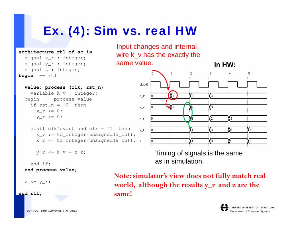
Ex. (4): Sim vs. real HW
In HW:
Timing of signals is the sameas in simulation.
Input changes and internalwire k_v has the exactly the same value.
Note: simulator’s view does not fully match real world, although the results y_r and z are the same!
Erno Salminen, TUT, 2013
#26/55 Department of Computer Systems
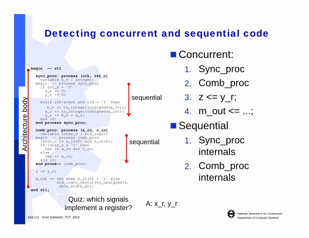
Detecting concurrent and sequential code
Concurrent:1. Sync_proc2. Comb_proc3. z <= y_r;4. m_out <= ...;
Sequential1. Sync_proc
internals2. Comb_proc
internals
begin -- rtl
sync_proc: process (clk, rst_n)variable k_v : integer;
begin -- process sync_procif rst_n = '0’x_r <= 0;y_r <= 0;
elsif clk'event and clk = '1' thenk_v := to_integer(unsigned(a_in));x_r <= to_integer(unsigned(a_in));y_r <= k_v + x_r;
end if;end process sync_proc;
comb_proc: process (a_in, c_in)variable inter_v : std_logic;
begin -- process comb_procinter_v := a_in(0) and c_in(0);if inter_v = '1' thenres <= a_in xor c_in;
else res <= a_in;
end if;end process comb_proc;
z <= y_r;
m_out <= res when b_in(0) = '1' elsestd_logic_vector(to_unsigned(z, data_width_g));
end rtl;
Arc
hite
ctur
e bo
dy sequential
sequential
Quiz: which signals implement a register? A: x_r, y_r
Erno Salminen, TUT, 2013

Department of Computer Systems
Generic parameters

#28/55 Department of Computer Systems
Generics Pass instance-specific information to an entity. Ability to parameterize models using generics. The values of generic parameters must be
computable at design time. Dynamic changes are not possible
Use generics instead of hard-coded values in interface!
Example:
entity mac isgeneric (data_width_g : integer := 4);
port (clk : in std_logic;rst_n : in std_logic;a_in : in std_logic_vector(data_width_g-1 downto 0);b_in : in std_logic_vector(data_width_g-1 downto 0);c_in : in std_logic_vector(data_width_g-1 downto 0);mac_out : out std_logic_vector(data_width_g*2-1 downto 0));
end mac;
Erno Salminen, TUT, 2013
#29/55 Department of Computer Systems
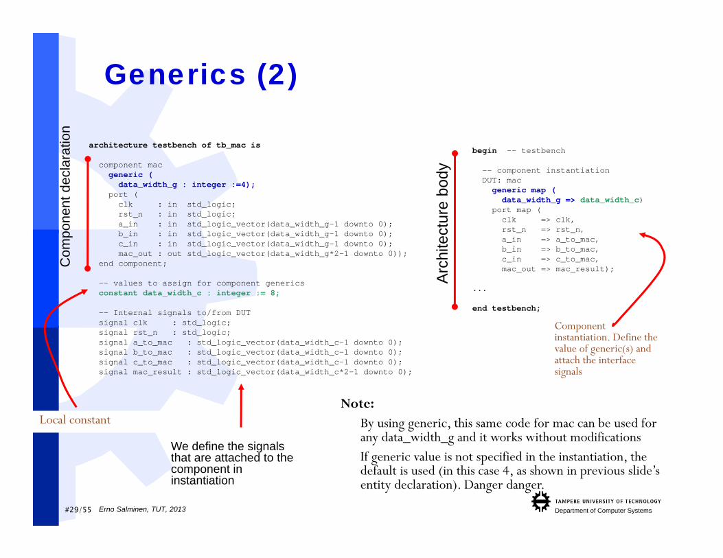
Generics (2)
architecture testbench of tb_mac is
component macgeneric (data_width_g : integer :=4);
port (clk : in std_logic;rst_n : in std_logic;a_in : in std_logic_vector(data_width_g-1 downto 0);b_in : in std_logic_vector(data_width_g-1 downto 0);c_in : in std_logic_vector(data_width_g-1 downto 0);mac_out : out std_logic_vector(data_width_g*2-1 downto 0));
end component;
-- values to assign for component genericsconstant data_width_c : integer := 8;
-- Internal signals to/from DUTsignal clk : std_logic;signal rst_n : std_logic;signal a_to_mac : std_logic_vector(data_width_c-1 downto 0);signal b_to_mac : std_logic_vector(data_width_c-1 downto 0);signal c_to_mac : std_logic_vector(data_width_c-1 downto 0);signal mac_result : std_logic_vector(data_width_c*2-1 downto 0);
begin -- testbench
-- component instantiationDUT: macgeneric map (data_width_g => data_width_c)
port map (clk => clk,rst_n => rst_n,a_in => a_to_mac,b_in => b_to_mac,c_in => c_to_mac,mac_out => mac_result);
...
end testbench;
Com
pone
nt d
ecla
ratio
n
Local constant
We define the signals that are attached to the component in instantiation
Arc
hite
ctur
e bo
dy
Component instantiation. Define the value of generic(s) and attach the interface signals
Note: By using generic, this same code for mac can be used for
any data_width_g and it works without modifications If generic value is not specified in the instantiation, the
default is used (in this case 4, as shown in previous slide’s entity declaration). Danger danger.
Erno Salminen, TUT, 2013

#30/55 Department of Computer Systems
Summary of genericsThey are great! Use them.
Erno Salminen, TUT, 2013
#31/55 Department of Computer Systems
Other statements
Erno Salminen, TUT, 2013
#32/55 Department of Computer Systems
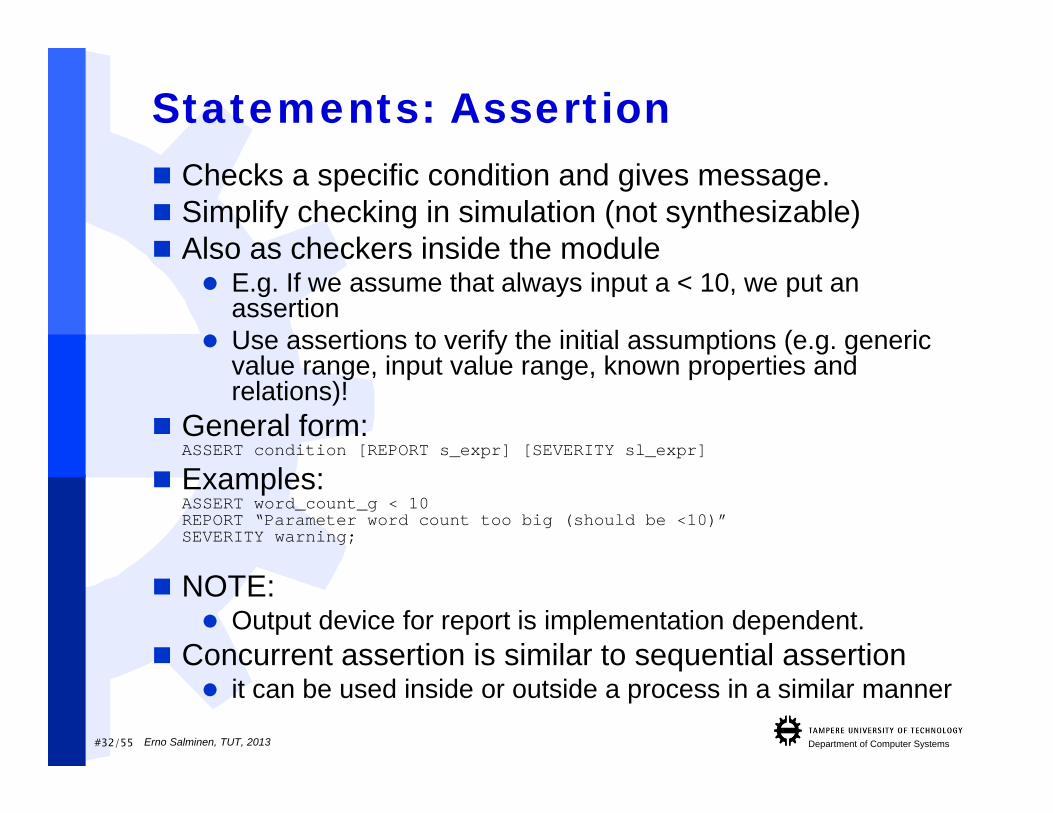
Statements: Assertion Checks a specific condition and gives message. Simplify checking in simulation (not synthesizable) Also as checkers inside the module
E.g. If we assume that always input a < 10, we put an assertion
Use assertions to verify the initial assumptions (e.g. generic value range, input value range, known properties and relations)!
General form:ASSERT condition [REPORT s_expr] [SEVERITY sl_expr]
Examples:ASSERT word_count_g < 10REPORT “Parameter word count too big (should be <10)”SEVERITY warning;
NOTE: Output device for report is implementation dependent.
Concurrent assertion is similar to sequential assertion it can be used inside or outside a process in a similar manner
Erno Salminen, TUT, 2013
#33/55 Department of Computer Systems
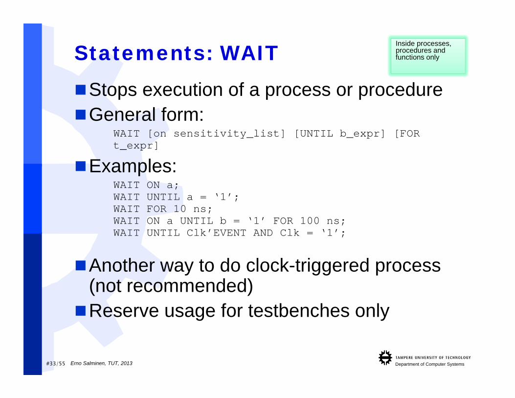
Statements: WAITStops execution of a process or procedureGeneral form:
WAIT [on sensitivity_list] [UNTIL b_expr] [FORt_expr]
Examples:WAIT ON a;WAIT UNTIL a = ‘1’;WAIT FOR 10 ns;WAIT ON a UNTIL b = ‘1’ FOR 100 ns;WAIT UNTIL Clk’EVENT AND Clk = ‘1’;
Another way to do clock-triggered process (not recommended)Reserve usage for testbenches only
Inside processes, procedures and functions only
Erno Salminen, TUT, 2013

#34/55 Department of Computer Systems
Statements: CASEAll possible choices must be considered or the
last choice must contain others clauseCASE expression IS
WHEN choice1 =>statements
WHEN choice2 =>statements
WHEN others =>statements
END CASE;
Example problem with DesignCompilersynthesis tool (from Synopsys): “Error: All possible string values of selector type not
covered by choices.” signal sel : std_logic;...
CASE sel ISWHEN ‘0’ => result <= a;WHEN ‘1’ => result <= b;
END CASE;
Inside processes, procedures and functions only
Erno Salminen, TUT, 2013

#35/55 Department of Computer Systems
Statements: CASE (2)Example:
CASE state ISWHEN “000” =>
output <= 0;WHEN “001”=>
output <= 1;WHEN “010”=>
output <= 2;WHEN “011”=>
output <= 3;WHEN OTHERS =>
output <= 4;END CASE;
Use when others => with case Otherwise, some tools want you to specify also
what happens with other std_logic_values, e.g. ”X11”, ”1Z1,” ”WHH”, ”UUU”
Inside processes, procedures and functions only
Erno Salminen, TUT, 2013
#36/55 Department of Computer Systems
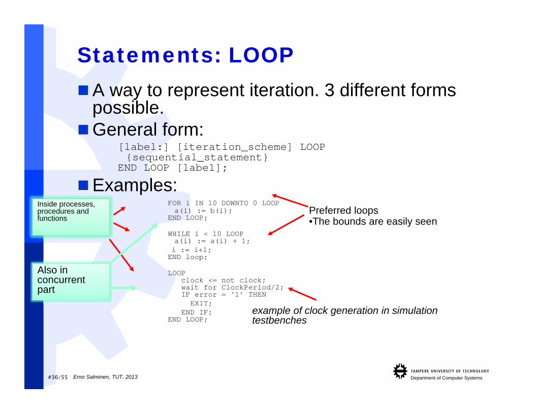
Statements: LOOPA way to represent iteration. 3 different forms
possible.General form:
[label:] [iteration_scheme] LOOP{sequential_statement}
END LOOP [label];
Examples:FOR i IN 10 DOWNTO 0 LOOPa(i) := b(i);
END LOOP;
WHILE i < 10 LOOPa(i) := a(i) + 1;i := i+1;END loop;
LOOPclock <= not clock;wait for ClockPeriod/2;IF error = ‘1’ THEN
EXIT; END IF;
END LOOP;
Preferred loops •The bounds are easily seen
Inside processes, procedures and functions
Also in concurrent part
example of clock generation in simulation testbenches
Erno Salminen, TUT, 2013
#37/55 Department of Computer Systems
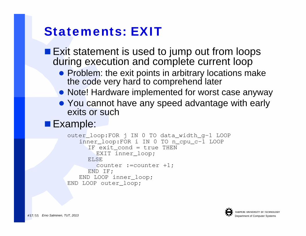
Statements: EXITExit statement is used to jump out from loops
during execution and complete current loop Problem: the exit points in arbitrary locations make
the code very hard to comprehend later Note! Hardware implemented for worst case anyway You cannot have any speed advantage with early
exits or suchExample:
outer_loop:FOR j IN 0 TO data_width_g-1 LOOPinner_loop:FOR i IN 0 TO n_cpu_c-1 LOOP
IF exit_cond = true THENEXIT inner_loop;
ELSEcounter :=counter +1;
END IF;END LOOP inner_loop;
END LOOP outer_loop;
Erno Salminen, TUT, 2013

#38/55 Department of Computer Systems
Statements: NEXT
Next statement is used to stop execution of statements in the loop for this iteration and go to the next iteration Same obfuscation problem as with exit
Example:outer_loop:FOR j IN 0 TO data_width_g-1 LOOP
inner_loop:FOR i IN 0 TO n_cpu_c-1 LOOPIF next_cond = true THENNEXT inner_loop;
ELSEcounter := counter +1;
END IF;END LOOP inner_loop;
END LOOP outer_loop;
Erno Salminen, TUT, 2013
#39/55 Department of Computer Systems
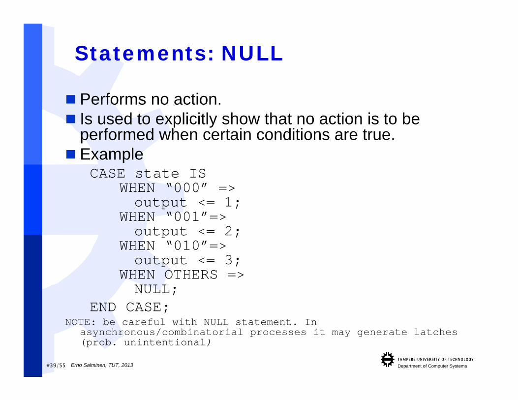
Statements: NULL
Performs no action. Is used to explicitly show that no action is to be
performed when certain conditions are true. Example
CASE state ISWHEN “000” =>output <= 1;
WHEN “001”=>output <= 2;
WHEN “010”=>output <= 3;
WHEN OTHERS =>NULL;
END CASE;NOTE: be careful with NULL statement. In
asynchronous/combinatorial processes it may generate latches (prob. unintentional)
Erno Salminen, TUT, 2013

#40/55 Department of Computer Systems
Statements: GENERATE Very important for hierarchical designGenerate statement makes possible to replicate
(FOR GENERATE) Component instantiations Concurrent statements
Also conditional replication/instantiation is possible (IF GENERATE) Whether a component is instantiated or not Whether concurrent statement/process is implemented or
not Note that there is no ELSE GENERATE
Example: DMA – direct memory access Parametrized amount of DMA channels Real code example from a research project
Erno Salminen, TUT, 2013
#41/55 Department of Computer Systems
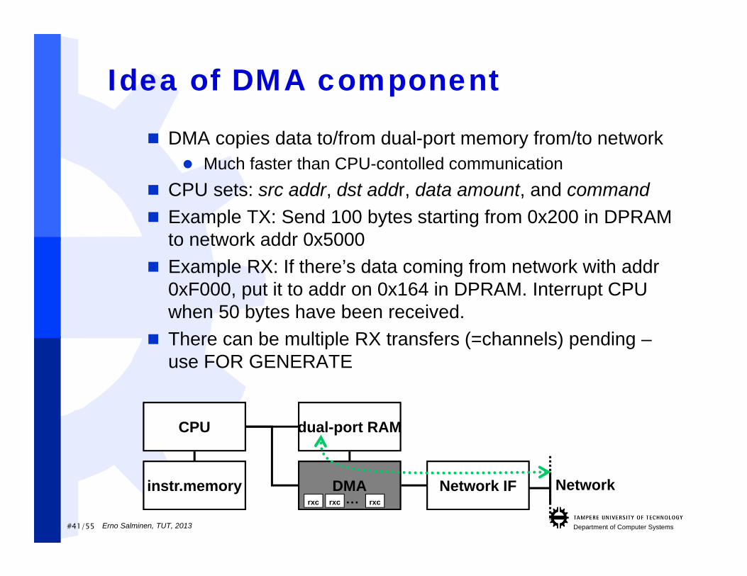
Idea of DMA component
DMA copies data to/from dual-port memory from/to network Much faster than CPU-contolled communication
CPU sets: src addr, dst addr, data amount, and command Example TX: Send 100 bytes starting from 0x200 in DPRAM
to network addr 0x5000 Example RX: If there’s data coming from network with addr
0xF000, put it to addr on 0x164 in DPRAM. Interrupt CPU when 50 bytes have been received.
There can be multiple RX transfers (=channels) pending –use FOR GENERATE
CPU d Mdual-port RAM
DMA Network IF Networkinstr.memoryrxc rxc rxc…
Erno Salminen, TUT, 2013
#42/55 Department of Computer Systems
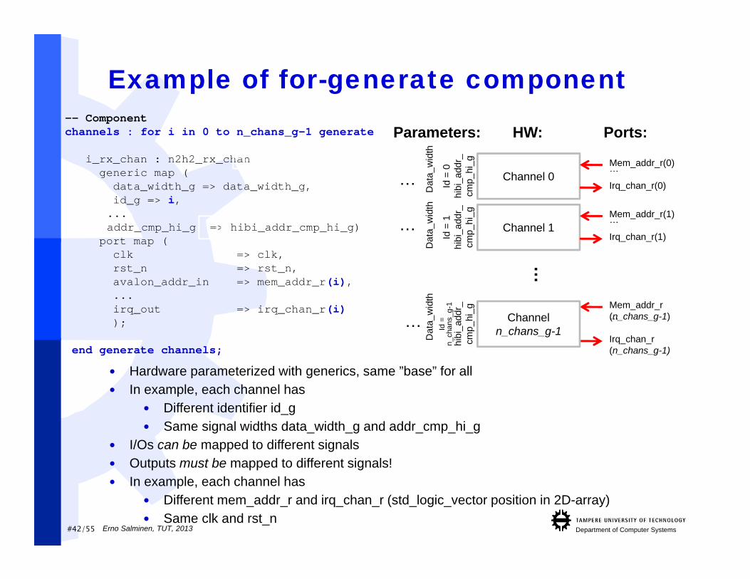
Example of for-generate component-- Component channels : for i in 0 to n_chans_g-1 generate
i_rx_chan : n2h2_rx_changeneric map (
data_width_g => data_width_g,id_g => i,...addr_cmp_hi_g => hibi_addr_cmp_hi_g)
port map (clk => clk,rst_n => rst_n,avalon_addr_in => mem_addr_r(i),...irq_out => irq_chan_r(i));
end generate channels;
Channel 0
Channel 1
…
Dat
a_w
idth
Id =
0hi
bi_a
ddr_
cmp_
hi_g
Parameters:
…
Dat
a_w
idth
Id =
1hi
bi_a
ddr_
cmp_
hi_g
…
Mem_addr_r(0)
Irq_chan_r(0)
…
HW: Ports:
Mem_addr_r(1)
Irq_chan_r(1)
…
Dat
a_w
idth
Id =
n_
chan
s_g-
1hi
bi_a
ddr_
cmp_
hi_g Mem_addr_r
(n_chans_g-1)
Irq_chan_r(n_chans_g-1)
…
Hardware parameterized with generics, same ”base” for all In example, each channel has
Different identifier id_g Same signal widths data_width_g and addr_cmp_hi_g
I/Os can be mapped to different signals Outputs must be mapped to different signals! In example, each channel has
Different mem_addr_r and irq_chan_r (std_logic_vector position in 2D-array) Same clk and rst_n
… Channel n_chans_g-1
Erno Salminen, TUT, 2013
#43/55 Department of Computer Systems
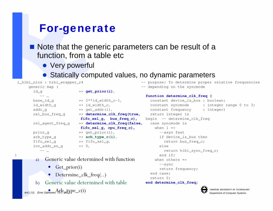
For-generate Note that the generic parameters can be result of a
function, from a table etc Very powerful Statically computed values, no dynamic parameters
i_hibi_nios : hibi_wrapper_r4generic map (
id_g => get_prior(i),-- …
base_id_g => 2**id_width_c-1,id_width_g => id_width_c,addr_g => get_addr(i),rel_bus_freq_g => determine_clk_freq(true,
fifo_sel_g, bus_freq_c),rel_agent_freq_g => determine_clk_freq(false,
fifo_sel_g, cpu_freq_c),prior_g => get_prior(i),arb_type_g => arb_type_c(i),fifo_sel_g => fifo_sel_g,inv_addr_en_g => 0,
-- …)
-- purpose: To determine proper relative frequencies -- depending on the syncmode
function determine_clk_freq (constant device_is_bus : boolean;constant syncmode : integer range 0 to 3;constant frequency : integer)return integer is
begin -- determine_clk_freqcase syncmode is
when 1 =>--asyn fastif device_is_bus then
return bus_freq_c;else
return hibi_sync_freq_c;end if;
when others =>--syncreturn frequency;
end case;return 0;
end determine_clk_freq;
a) Generic value determined with function Get_prior(i) Determine_clk_freq(..)
b) Generic value determined with table Arb_type_c(i)Erno Salminen, TUT, 2013
#44/55 Department of Computer Systems
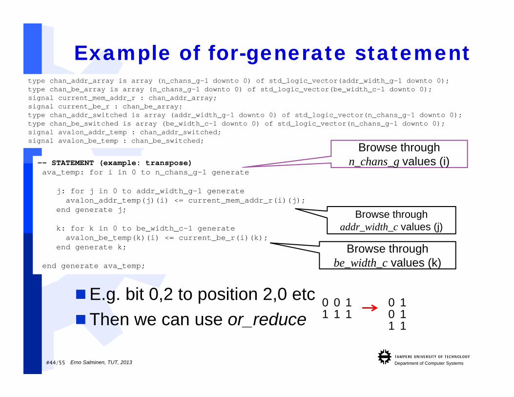
Example of for-generate statement
E.g. bit 0,2 to position 2,0 etcThen we can use or_reduce
-- STATEMENT (example: transpose)ava_temp: for i in 0 to n_chans_g-1 generate
j: for j in 0 to addr_width_g-1 generateavalon_addr_temp(j)(i) <= current_mem_addr_r(i)(j);
end generate j;
k: for k in 0 to be_width_c-1 generateavalon_be_temp(k)(i) <= current_be_r(i)(k);
end generate k;
end generate ava_temp;
Browse through addr_width_c values (j)
Browse through be_width_c values (k)
type chan_addr_array is array (n_chans_g-1 downto 0) of std_logic_vector(addr_width_g-1 downto 0);type chan_be_array is array (n_chans_g-1 downto 0) of std_logic_vector(be_width_c-1 downto 0);signal current_mem_addr_r : chan_addr_array;signal current_be_r : chan_be_array;type chan_addr_switched is array (addr_width_g-1 downto 0) of std_logic_vector(n_chans_g-1 downto 0);type chan_be_switched is array (be_width_c-1 downto 0) of std_logic_vector(n_chans_g-1 downto 0);signal avalon_addr_temp : chan_addr_switched;signal avalon_be_temp : chan_be_switched;
Browse through n_chans_g values (i)
0 0 11 1 1
001
111
Erno Salminen, TUT, 2013

#45/55 Department of Computer Systems
SubprogramsVariables inside subprograms are localVariables are valid only during subprogram
executionContain sequential statementsFunctions:
can return one argument (can be compound type) all parameters are input parameters
FUNCTION n_one_bits(vec : BIT_VECTOR) RETURN INTEGER ISVARIABLE tmp : INTEGER;
BEGINtmp := 0;FOR i IN vec’RANGE LOOPIF vec(i) = ‘1’ THENtmp := tmp+1;
ELSEtmp := tmp;
END IF;END LOOP;RETURN tmp;
END n_one_bits;
Erno Salminen, TUT, 2013

#46/55 Department of Computer Systems
Subprograms (2)Procedures: can contain several input, output and inout
parameters
PROCEDURE n_one_bits (SIGNAL vec : IN BIT_VECTOR;VARIABLE int : OUT INTEGER) IS
BEGINint := 0;FOR i IN vec’range LOOP IF vec(i) = ‘1’ THENint := int+1;
ELSEint := int;
END IF;END LOOP;
END n_one_bits;
Erno Salminen, TUT, 2013
#47/55 Department of Computer Systems
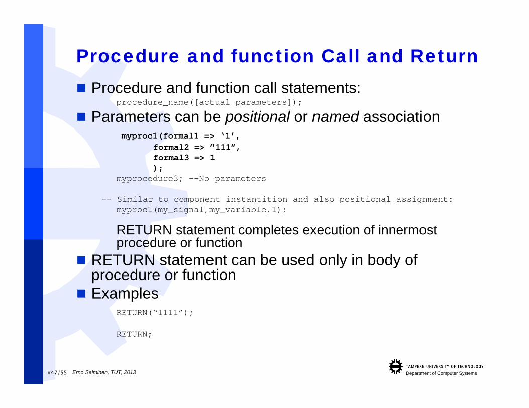
Procedure and function Call and Return Procedure and function call statements:
procedure_name([actual parameters]);
Parameters can be positional or named associationmyproc1(formal1 => ‘1’,
formal2 => ”111”,formal3 => 1);
myprocedure3; --No parameters
-- Similar to component instantition and also positional assignment:myproc1(my_signal,my_variable,1);
RETURN statement completes execution of innermost procedure or function
RETURN statement can be used only in body of procedure or function
ExamplesRETURN(“1111”);
RETURN;
Erno Salminen, TUT, 2013

#48/55 Department of Computer Systems
Simple mistakes one usually does…
Erno Salminen, TUT, 2013

#49/55 Department of Computer Systems
VHDL Pitfalls1. Identifiers
VHDL isn’t case sensitive (e.g. Input and input are the same) (But some tool’s are…)
2. Misspelled If statement ELSIF written as ELSE IF
3. Wrong string delimiters ‘0001’ instead of “0001”, or “0” instead of ‘0’
4. Misused reserved words reserved words used as object names: IN, OUT,
BUFFER, AND, NAND, OR 5. Incomplete case statement
VHDL requires all conditions to be presented
Erno Salminen, TUT, 2013
#50/55 Department of Computer Systems
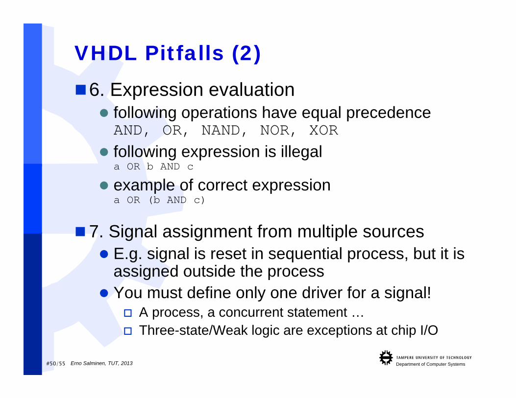
VHDL Pitfalls (2)6. Expression evaluation following operations have equal precedenceAND, OR, NAND, NOR, XOR
following expression is illegala OR b AND c
example of correct expressiona OR (b AND c)
7. Signal assignment from multiple sources E.g. signal is reset in sequential process, but it is
assigned outside the process You must define only one driver for a signal!
A process, a concurrent statement … Three-state/Weak logic are exceptions at chip I/O
Erno Salminen, TUT, 2013
#51/55 Department of Computer Systems
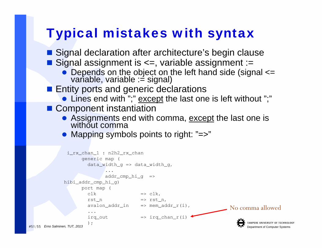
Typical mistakes with syntax Signal declaration after architecture’s begin clause Signal assignment is <=, variable assignment :=
Depends on the object on the left hand side (signal <= variable, variable := signal)
Entity ports and generic declarations Lines end with ”;” except the last one is left without ”;”
Component instantiation Assignments end with comma, except the last one is
without comma Mapping symbols points to right: ”=>”
i_rx_chan_1 : n2h2_rx_changeneric map (
data_width_g => data_width_g,...addr_cmp_hi_g =>
hibi_addr_cmp_hi_g)port map (
clk => clk,rst_n => rst_n,avalon_addr_in => mem_addr_r(i),...irq_out => irq_chan_r(i));
No comma allowed
Erno Salminen, TUT, 2013

#52/55 Department of Computer Systems
Mistakes in sim. vs. synthesis
The process sensitivity list is incomplete! May hide bugs in the design Synthesis ignores sensitivity list but simulation
relies on its completeness Always use compile option –check_synthesis
Using non-synthesizable structures ordatatypes
E.g. Using don’t care-operator: E.g. when ”1--” => … May simulate well (Modelsim supports) but does
not synthesize!
Erno Salminen, TUT, 2013
#53/55 Department of Computer Systems
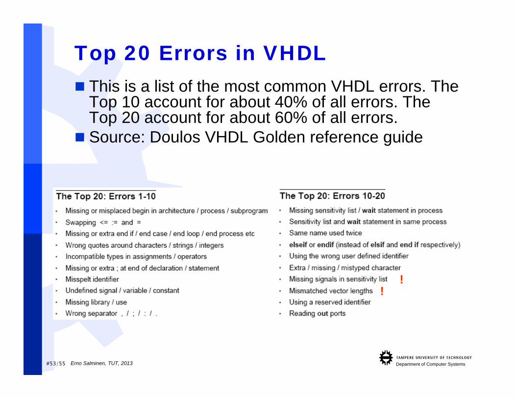
Top 20 Errors in VHDL This is a list of the most common VHDL errors. The
Top 10 account for about 40% of all errors. The Top 20 account for about 60% of all errors.
Source: Doulos VHDL Golden reference guide
!!
Erno Salminen, TUT, 2013
#54/55 Department of Computer Systems
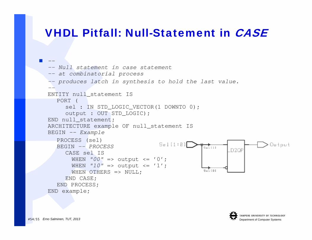
VHDL Pitfall: Null-Statement in CASE
---- Null statement in case statement-- at combinatorial process-- produces latch in synthesis to hold the last value.--ENTITY null_statement IS
PORT (sel : IN STD_LOGIC_VECTOR(1 DOWNTO 0);output : OUT STD_LOGIC);
END null_statement;ARCHITECTURE example OF null_statement ISBEGIN -- Example
PROCESS (sel)BEGIN -- PROCESS
CASE sel ISWHEN "00" => output <= ’0’;WHEN "10" => output <= ’1’;WHEN OTHERS => NULL;
END CASE;END PROCESS;
END example;
Erno Salminen, TUT, 2013
#55/55 Department of Computer Systems
SummaryComb logic described with concurrent
statements and processes. Seq. logic onlywith processesGenerics, if-generate, for-generate and
assertions are greatLoop bounds, signal widths, signals slicing
indices, and generic values must be knownat compile-time (=synthesis-time)
Erno Salminen, TUT, 2013