Thrane & Thrane
60
TT-3026L easyTrack Transceiver Installation Manual 1/60 Thrane & Thrane TT-3026L easyTrack Transceiver Installation Manual Copyright© Thrane & Thrane A/S ALL RIGHS RESERVED 2005, Thrane & Thrane A/S Information in this document is subject to change without notice and does not represent a commitment on the part of Thrane & Thrane A/S. Document number: 98-121788 Revision: A Release Date: 16 th of December 2005
Transcript of Thrane & Thrane

TT-3026L easyTrack Transceiver Installation Manual
1/60
Thrane & Thrane
TT-3026L easyTrack Transceiver
Installation Manual
Copyright© Thrane & Thrane A/S ALL RIGHS RESERVED
2005, Thrane & Thrane A/S
Information in this document is subject to change without notice and does not represent a commitment on the part of Thrane & Thrane A/S. Document number: 98-121788 Revision: A Release Date: 16th of December 2005

TT-3026L easyTrack Transceiver Installation Manual
2/60
This page is intentionally left blank

TT-3026L easyTrack Transceiver Installation Manual
3/60
SAFETY SUMMARY The following general safety precautions must be observed during all phases of operation, service and repair of this equipment. Failure to comply with these precautions or with specific warnings elsewhere in this manual violates safety standards of design, manufacture and intended use of the equipment. Thrane & Thrane A/S assumes no liability for the customer’s failure to comply with these requirements. MICROWAVE RADIATION HAZARDS During transmission this unit radiates microwaves from the antenna. This radiation may be hazardous if exposed directly to humans close to the antenna. Make sure that nobody is closer than the recommended minimum safety distance of 1 ft. (0.3 meters) during use of the transceiver. KEEP AWAY FROM LIVE CIRCUITS Operating personnel must not remove equipment covers. Only qualified maintenance personal must make component replacement and internal adjustment. Under certain conditions, dangerous voltages may exist even with the cable removed. To avoid injuries, always disconnect power and discharge circuits before touching them.

TT-3026L easyTrack Transceiver Installation Manual
4/60
This page is intentionally left blank

TT-3026L easyTrack Transceiver Installation Manual
5/60
List of Contents: 1 Introduction ........................................ 9
1.1 Initial Inspection.......................................................9 1.2 Storage................................................................... 10 1.3 Repacking for shipment.......................................... 10 1.4 Additional manuals................................................. 11 1.5 Abbreviations......................................................... 11
2 System Description............................. 13 2.1 TT-3026L easyTrack Transceiver ............................ 14 2.2 TT-3616T Interconnection Box ................................ 15 2.3 TT-3606L Message Terminal ................................... 16 2.4 EasyMail................................................................. 16 2.5 Accessories ............................................................ 17
3 Registration ...................................... 18 4 Hardware Installation ......................... 21
4.1 Installation of TT-3026L........................................... 21 4.1.1 Mounting options............................................. 21
4.1.1.1 Drilled holes on a flat surface.................... 21 4.1.1.2 Pole mount 1” ........................................... 22 4.1.1.3 Adjustable Pole/Railing Mount.................. 23
4.1.2 Antenna Mounting Conditions ......................... 23 4.1.3 Safety Distance for Antenna Units..................... 25
4.2 Wiring the easyTrack System ................................. 25 4.2.1 Grounding ....................................................... 26 4.2.2 Remote on/off .................................................. 26 4.2.3 Power Connection ........................................... 27 4.2.4 Power Requirements........................................ 27 4.2.5 Alarm Button.................................................... 27 4.2.6 General Purpose I/O Ports............................... 27
4.3 Installation of TT-3616T Interconnection Box........... 29 4.3.1 Mounting of transceiver cable ......................... 30 4.3.2 Grounding of Interconnection Box ................... 32 4.3.3 Data Terminal Equipment connection .............. 33 4.3.4 Power & I/O Connection .................................. 33
4.4 Connecting a Tacho graph ..................................... 35 4.5 Troubleshooting ..................................................... 38 4.6 DTE connection via DB9 female connector.............. 40

TT-3026L easyTrack Transceiver Installation Manual
6/60
4.7 Technical Specification .......................................... 41 5 Software Installation............................ 43
5.1 About easyMail ..................................................... 43 5.2 Before you install.................................................... 43 5.3 easyMail installation............................................... 43
5.3.1 CD startup ....................................................... 43 5.3.2 Starting the installation.................................... 44 5.3.3 Start up window............................................... 45 5.3.4 Welcome screen ............................................. 45 5.3.5 Disclaimer window.......................................... 46 5.3.6 Customer information...................................... 46 5.3.7 Destination folder............................................ 47 5.3.8 Ready to install ................................................ 48 5.3.9 Install completed............................................. 48 5.3.10 Starting easyMail............................................. 49
5.4 Running easyMail for the first time ......................... 49 5.5 easyMail basic setup .............................................. 51 5.6 Getting new versions of easyMail........................... 53
6 Test of the system ............................... 54 6.1 Link test ................................................................. 54
7 Maintenance guidelines ...................... 55 7.1 Handling Precautions ............................................. 55
8 Appendix A ........................................ 56 8.1 Mounting stencil..................................................... 56
9 Appendix B ........................................ 57 9.1 Interconnection box TT-3616B................................ 57

TT-3026L easyTrack Transceiver Installation Manual
7/60
List of Figures: Figure 1 TT-3026L easyTrack Mini-C Transceiver ..................9 Figure 2 easyTrack system example .................................... 13 Figure 3 TT-3026L easyTrack Transceiver……………………..14 Figure 4 TT-3616B/T Interconnection Box............................. 15 Figure 5 TT-3606L Message Terminal ................................... 16 Figure 6 Page 1 of the Service Activation Registration Form. 19 Figure 7 Minimum easyTrack system ................................... 21 Figure 8 1" Pole mounting .................................................... 22 Figure 9 Vertical and Horizontal adjustable pole mount ....... 23 Figure 10 Viewing Angle to the Horizon ............................... 24 Figure 11 Mounting near pole (overhead view).................... 24 Figure 12 TT-3616T Interconnection box .............................. 29 Figure 13 TT-3616T Interconnection Box Interior.................. 30 Figure 14 Alternative grounding of Interconnection Box ...... 33 Figure 15 Grounding scheme A............................................ 36 Figure 16 Grounding scheme B ............................................ 37 Figure 17 Normal Tacho graph signal................................... 38 Figure 18 Tacho graph signal with missing GND reference.. 39 Figure 19 Tacho graph signal with correct GND reference... 39 Figure 20 Sub-D with screw terminals .................................. 40 Figure 21 easyMail with no connection to easyTrack............ 50 Figure 22 easyMail connected to easyTrack, good satellite
signal and GPS fix.......................................................... 50 Figure 23 Example of Mobile number .................................. 52 Figure 24 The login menu..................................................... 52 Figure 25 Example when logged in to East Atlantic.............. 52 Figure 26 Choose your Service Provider.............................. 53 Figure 27 Land Earth Stations (LESs) of your Inmarsat Service
Provider ........................................................................ 53 Figure 28 The link test dialog ............................................... 54 Figure 29 Mounting stencil ................................................... 56 Figure 30 TT-3616B Interconnection box .............................. 57 Figure 31 Interconnection Box Interior Arrangement ........... 58

TT-3026L easyTrack Transceiver Installation Manual
8/60
List of Tables: Table 1 Answers to selected questions in SARF.................... 20 Table 2 Radiated intensity.................................................... 25 Table 3 Cable pin assignment.............................................. 26 Table 4 Transceiver Cable Terminal Block .......................... 32 Table 5 Power & I/O Cable Terminal Block.......................... 34 Table 6 Jumper index........................................................... 34 Table 7 AUX1-AUX3 input characteristics ............................ 35 Table 8 Sub-D wire connections........................................... 40 Table 9 TT-3026L Technical Spectifications .......................... 42 Table 10 Transceiver Cable Terminal Block......................... 59 Table 11 Power & I/O Cable Terminal Block ........................ 60

TT-3026L easyTrack Transceiver Installation Manual
9/60
1 INTRODUCTION This manual provides instructions for installing a TT-3026L easyTrack Mini-C Transceiver for land mobile use. A wide variety of options and accessories may be linked together with the easyTrack transceiver. Those associated with the installation of the TT-3026L are described in this manual.
Figure 1 TT-3026L easyTrack Mini-C Transceiver
1.1 INITIAL INSPECTION
WARNING To avoid hazardous electrical shock, do not perform electrical tests if there is any sign of shipping damage to any portion of the outer cover. Read the safety summary at the front of this manual before installing or operating the TT-3026L easyTrack Transceiver.

TT-3026L easyTrack Transceiver Installation Manual
10/60
Inspect the shipping carton immediately upon receipt for evidence of mishandling during the transport. If the shipping carton is severely damaged or water stained, request the carrier's agent to be present when opening the carton. Save the carton packing material for future use. Contents of the shipment should be as listed in the enclosed packing list. If the contents are incomplete, if there is mechanical damage or defect, or if the TT-3026L does not work properly, notify your dealer. After you unpack the TT-3026L please:
• Inspect it thoroughly for hidden damaged, loose components or loose fittings.
• Inspect the cable harness for stress, loose or broken wires, or broken cable ties.
• Examine all the components for loose or missing hardware.
• Tighten all loose hardware.
1.2 STORAGE
The TT-3026L easyTrack may be stored or shipped in temperatures within the limits -40° C to +80° C. It is recommended that the TT-3026L easyTrack is unpacked immediately on delivery.
1.3 REPACKING FOR SHIPMENT
The shipping carton for the TT-3026L easyTrack has been carefully designed to protect the transceiver and its accessories during shipment. This carton and its associated packing material should be used when repackaging for shipment. Attach a tag indicating the type of service required, return address, model number and full serial number. Mark the carton FRAGILE to ensure careful handling. If the original shipping carton is not available, the following general instructions should be used for repackaging with commercially available material.

TT-3026L easyTrack Transceiver Installation Manual
11/60
• Wrap the TT-3026L easyTrack in heavy paper or plastic. Attach a tag indicating the type of service required, return address, model number and full serial number.
• Use a strong shipping container, e.g., a double-walled carton made of 160 kg test material.
• Seal the shipping container FRAGILE to ensure careful handling.
1.4 ADDITIONAL MANUALS
On the easyTrack CD ROM included, you will find the following manuals:
Ref. T&T number Title [1] TT 98-121798 TT-3026DMS User Manual1 [2] TT 98-116080 TT-3026 Software Interface
Reference Manual. [3] TT 98-121016 TT-3606L Installation and User
Manual. A windows® based configuration tool is available from Thrane & Thrane through the normal distribution channels. It can be useful for configuration of the advanced features described in ref. [2].
1.5 ABBREVIATIONS
AA Accounting Authority EMC Electromagnetic Compatibility GPS Global Positioning System HPA High Power Amplifier (radio transmitter) ISN Inmarsat Serial Number of the easyTrack ISP Inmarsat Service Provider LES Inmarsat-C Land Earth Station
1 Although targeted at maritime users, 95% of the information is relevant for land mobile users as well.

TT-3026L easyTrack Transceiver Installation Manual
12/60
LESO Inmarsat-C Land Earth Station Operator LNA Low Noise Amplifier (radio receiver) MES Mobile Earth Station NCS Inmarsat-C Network Coordination Station Opt. Short for option PSA Point of Service Activation PVT Performance Verification Test SARF Service Activation Registration Form SCADA Supervisory Control And Data Acquisition

TT-3026L easyTrack Transceiver Installation Manual
13/60
2 SYSTEM DESCRIPTION The system shown in Figure 2 corresponds to a TT-3026L easyTrack setup, where distance and speed are derived from pulses from the tacho graph normally found in the vehicle. The individual products are briefly introduced in this section. For detailed information about installation please refer to the following sections.
TT-3026L
TT-3616T or
TT-3616B
TT-10236A
Tachograph
Power 12–24 V DC
Figure 2 easyTrack system example
A general introduction to the Inmarsat C network is given in the User Manual [1].
TT-3026L easyTrack Transceiver Installation Manual
14/60
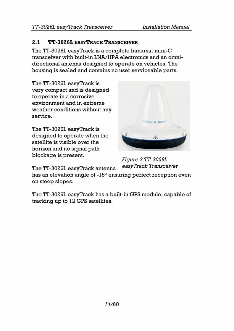
2.1 TT-3026L EASYTRACK TRANSCEIVER
The TT-3026L easyTrack is a complete Inmarsat mini-C transceiver with built-in LNA/HPA electronics and an omni-directional antenna designed to operate on vehicles. The housing is sealed and contains no user serviceable parts. The TT-3026L easyTrack is very compact and is designed to operate in a corrosive environment and in extreme weather conditions without any service. The TT-3026L easyTrack is designed to operate when the satellite is visible over the horizon and no signal path blockage is present. The TT-3026L easyTrack antenna has an elevation angle of -15° ensuring perfect reception even on steep slopes. The TT-3026L easyTrack has a built-in GPS module, capable of tracking up to 12 GPS satellites.
Figure 3 TT-3026L easyTrack Transceiver

TT-3026L easyTrack Transceiver Installation Manual
15/60
2.2 TT-3616T INTERCONNECTION BOX
For connecting the TT-3026L easyTrack to peripheral equipment, it is recommended to use the optional TT-3616T Interconnection Breakout Box, designed to be mounted anywhere inside a vehicle and to be located up to 20 metres away from the easyTrack using a special connection cable
Figure 4 TT-3616B/T Interconnection Box
If the tacho graph input is not needed, the TT-3616B Interconnection Box can be used as well.

TT-3026L easyTrack Transceiver Installation Manual
16/60
2.3 TT-3606L MESSAGE TERMINAL
The TT-3606L is a dedicated message terminal to be used in conjunction with the TT-3026L transceiver in order to send and receive messages to and from the vehicle.
Figure 5 TT-3606L Message Terminal
The TT-3606L Message Terminal is equipped with a touch screen. For further information concerning the installation and use of the TT-3606L please refer to [3].
2.4 EASYMAIL
EasyMail is a PC program, which can be used to control the TT-3026L Inmarsat-C transceiver. With easyMail you can easily send and receive e-mail, SMS, fax and telex messages, set up position reporting and many other things.

TT-3026L easyTrack Transceiver Installation Manual
17/60
2.5 ACCESSORIES
Product number:
Product description Picture
Opt. 101 Standard 1” pole mount kit
Opt. 103 Adjustable pole/railing mount kit
Opt. 940 Connection cable, 5 meters, with 90° angular plug
Opt. 941 Connection cable, 5 meters
Opt. 942 Connection cable, 10 meters
Opt. 943 Connection cable, 20 meters
TT-3606L Message Terminal
TT-3026L easyTrack Transceiver Installation Manual
18/60
3 REGISTRATION Before use of the easyTrack transceiver on the Inmarsat-C system it must be registered to the system, which involves a little paper work. This is done using the SARF (Service Activation Registration Form) supplied with the easyTrack MES. Page 1 of the SARF is shown in Figure 6. The SARF for registration of Land Mobile MES can also be found on www.inmarsat.org (CUSTOMER SUPPORT -> SERVICE ACTIVATION). The site also contains notes on how to complete the land mobile form. The Service Activation Registration Form contains different abbreviations that will be explained here. The easyTrack MES must be registered at either a PSA company or directly to the ISP. A PSA is a company handling the activation of Inmarsat mobiles and is short for Point of Service Activation. ISP is the company that provides the Inmarsat service and is short for Inmarsat Service Provider. In many cases the PSA and ISP is the same company that also operates a Land Earth Station (LES). The local PSA or ISP can be obtained by following the guidelines in the registration form. The Service Activation Registration Form also includes information needed to find out how to pay the bill for the Inmarsat-C service. This payment will be done directly to the Accounting Authority. In many cases the Accounting Authority (AA) is also the same company as the Inmarsat Service Provider (ISP). In addition to the general information like name, address, etc. the ISN of the easyTrack MES must be specified. The ISN is located on the Delivery Note and in the bottom of the easyTrack MES. Refer to Table 1 for answers to selected SARF questions.

TT-3026L easyTrack Transceiver Installation Manual
19/60
Figure 6 Page 1 of the Service Activation Registration Form

TT-3026L easyTrack Transceiver Installation Manual
20/60
Question in SARF Answer Environment usage
When installed in vehicles: Land Mobile.
The System?
Inmarsat-C
Mobile Earth Station (MES) manufacturer
Thrane & Thrane A/S
Mobile Earth Station (MES) model
TT-3026L
Table 1 Answers to selected questions in SARF
When the easyTrack MES is registered at the ISP it is ready to be used on the Inmarsat-C network. The ISP has returned a Mobile Number for the easyTrack MES and prior to operating the easyTrack MES it must be configured with this Mobile Number. This is easiest done using easyMail. For further information on installation of easyMail please refer to section 5. Advanced users can make this configuration directly via the terminal interface using Windows® HyperTerminal or equivalent. For further information on the terminal interface please refer to the Software Interface Reference Manual [2].

TT-3026L easyTrack Transceiver Installation Manual
21/60
4 HARDWARE INSTALLATION The TT-3026L easyTrack is equipped with an 18-pin female connector and is meant for flat surface mounting, or pole mounting using an optional adaptor. See section 4.1.1. Figure 7 shows the minimal easyTrack system configuration, where the transceiver is pre-configured for tracking. Remember to short the Remote On/Off pin to GND (refer to section 4.2.2 for Remote On/Off installation instructions).
Figure 7 Minimum easyTrack system
4.1 INSTALLATION OF TT-3026L
This section describes the physical mounting of the TT-3026L easyTrack. Refer to sections 4.1.2 and 4.1.3 for guidelines on choosing the most effective and safest mounting location.
4.1.1 MOUNTING OPTIONS
The TT-3026L easyTrack transceivers are designed for mounting on one of 2 optional pole mount adaptors. In addition the easyTrack transceiver is designed for mounting on a flat surface using screws.
4.1.1.1 DRILLED HOLES ON A FLAT SURFACE
• Drill the 4 holes (3 for the mounting screws, 1 for cable access) using the mounting stencil in Appendix A.
Power Suppy10,5 -32 V DC

TT-3026L easyTrack Transceiver Installation Manual
22/60
• Place the friction gasket on the surface. • Connect the cable and mount the screws.
4.1.1.2 POLE MOUNT 1”
40-3026 Opt. 101 is a standard 1” pole mount, Illustrated in Figure 8.
• Pull the cable in the pole and adapter. • Connect the cable to the transceiver. • Mount the adapter on the transceiver using screws. • Tighten the adapter to the pole. • Adjustable between 20 - 35 millimetre
NOTE: THE POLE MOUNT DEVICE HAS TO BE DISCONNECTED FROM THE TRANSCEIVER WHEN THE CABLE IS MOUNTED.
Figure 8 1" Pole mounting

TT-3026L easyTrack Transceiver Installation Manual
23/60
4.1.1.3 ADJUSTABLE POLE/RAILING MOUNT
403026 Opt. 103 is an adjustable pole/railing mount shown in Figure 9
• Attach the pole mount to the transceiver using the 3 screws.
• Mount the device to the pole in one of the 2 directions. • Connect the cable.
Figure 9 Vertical and Horizontal adjustable pole mount
4.1.2 ANTENNA MOUNTING CONDITIONS
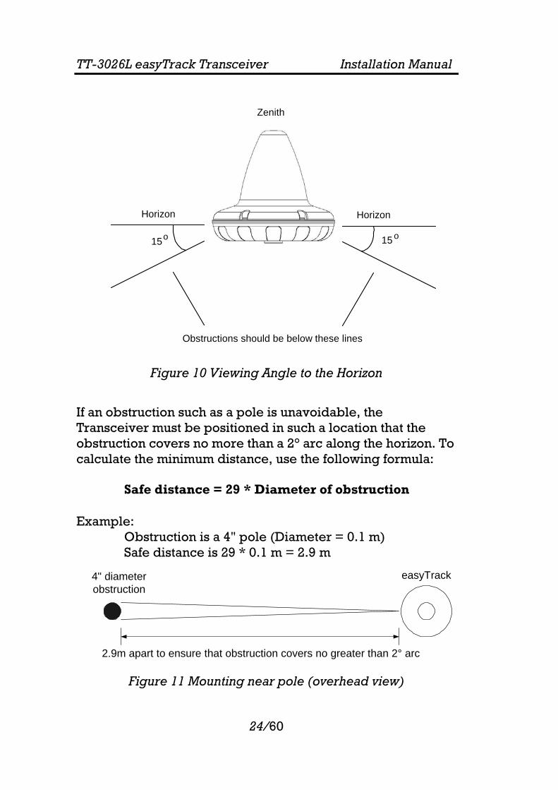
When installing the TT-3026L easyTrack, find a location that is as free from obstructions as possible. Also maintain a certain distance to other antennas. The antenna is designed to provide satellite coverage even when the vehicle is tilted up to 15°. To maintain this coverage the antenna should be free from obstructions in the area down to 15° below the horizon (see Figure 10). Any compromise in this recommendation could degrade performance.
TT-3026L easyTrack Transceiver Installation Manual
24/60
Figure 10 Viewing Angle to the Horizon
If an obstruction such as a pole is unavoidable, the Transceiver must be positioned in such a location that the obstruction covers no more than a 2° arc along the horizon. To calculate the minimum distance, use the following formula: Safe distance = 29 * Diameter of obstruction Example:
Obstruction is a 4" pole (Diameter = 0.1 m) Safe distance is 29 * 0.1 m = 2.9 m
Figure 11 Mounting near pole (overhead view)
2.9m apart to ensure that obstruction covers no greater than 2° arc
easyTrack4" diameterobstruction
15
Horizon
15
Horizon
Zenith
Obstructions should be below these lines
oo

TT-3026L easyTrack Transceiver Installation Manual
25/60
4.1.3 SAFETY DISTANCE FOR ANTENNA UNITS
When transmitting, the electromagnetic field radiated from the antenna can be harmful. To avoid danger, keep a distance of 1 ft. (30 cm.) from the transceiver. To be sure that this distance is respected, the TT-3026L easyTrack is provided with a label declaring a minimum safety distance of 1 ft. (30 cm.) on the antenna. The relation between the power intensity and distance is as follows:
Distance (m) from antenna Radiated intensity (W/m2) 0.20 10 0.13 25 0.07 100
Table 2 Radiated intensity
4.2 WIRING THE EASYTRACK SYSTEM
3 lengths of connecting cables are available from T&T: 5m, 10m and 20m (refer to section 2.5 for option numbers). Table 4 shows the description and functions of the TT-3026L easyTrack cable.

TT-3026L easyTrack Transceiver Installation Manual
26/60
Wire colour Function Description
2 x Red 1mm2 DC + 12-24 VDC (Battery Positive input)
2 x Black 1mm2 DC - DC - (Battery Negative input)
Yellow ON/OFF Remote ON/OFF
White GND GND
Orange GND GND
Black/Violet 3V3 out 3.3V out max. 100mA. for terminal equipment
Black/Blue Grey Black/Yellow Black/Grey Brown Black/Green
I/O port 1 - 2 - 3 - 4 - 5 - 6
I/O port 1 reserved for Land Mobile Alert.
I/O port 2-6 are user configurable 3.3V I/O’s, 5V tolerant. Each open-collector output sinks 25mA.
Green RD ** RS232 Receive
Black/Red TD ** RS232 Transmit
Violet RTS ** RS232 Request to send
Blue CTS ** RS232 Clear to send
Table 3 Cable pin assignment
** DCE (Data Communication Equipment) naming.
4.2.1 GROUNDING
Make sure that the shield of the cable is connected to a proper ground, i.e. vehicles structure. This is very important in order to safely bypass interference from radio equipment and other environmental noise sources.
4.2.2 REMOTE ON/OFF
The Remote ON/OFF (yellow wire) is a unique feature for the TT-3026L easyTrack Transceiver. When this wire is left floating the Transceiver is turned off and when the wire is shorted to GND (white or orange wire), the Transceiver will be switched on. This makes it possible for external equipment to perform remote power control of the TT-3026L easyTrack Transceiver. An external relay or solid-state switch can control the power.

TT-3026L easyTrack Transceiver Installation Manual
27/60
To control the transceiver from the built-in sleep mode function the remote on/off wire must be left floating (off).
4.2.3 POWER CONNECTION
The power connections of the TT-3026L consist of 4 wires (two red and two black). All 4 wires MUST be used. The power connection input is floating (i.e., there is no galvanic connection from any of the battery poles to the connector housing = GND = cable shield).
4.2.4 POWER REQUIREMENTS
The TT-3026L easyTrack transceiver is designed to operate on floating DC in the nominal range 12V to 24V, which makes an AC/DC converter needed, in case the system is to work in an AC environment. In case an AC/DC converter is used, please make sure to leave the output floating, i.e. do NOT connect the negative wire to vehicle structure. The transceiver has an actual working voltage range of 10.5V to 32V to accommodate power supply variations outside the nominal range.
4.2.5 ALARM BUTTON
On TT-3026L, the I/O port 1 is reserved for land mobile alarm button. If the land mobile alert function is enabled, an alert will be transmitted when the button is pressed (thus shortening I/O port 1 to GND).
4.2.6 GENERAL PURPOSE I/O PORTS
The TT-3026L easyTrack also contain some configurable input/output ports. On TT-3026L, I/O 2 to 6 are configurable by the user. When used as outputs, the ports have the following characteristics:
• Open collector output. • Internal 2.2kOhm pull-up resistor to 3.3VDC.

TT-3026L easyTrack Transceiver Installation Manual
28/60
• Voltage allowed between GND and the output pin is 0V to 5V.
• Maximum allowed current into the I/O pin is 25mA. Note: There is no current limiter integrated in the output, thus the user must ensure, that the load connected is within limits.
When used as inputs, the ports have the following characteristics:
• Internal 2.2kOhm pull-up resistor to 3.3VDC. • To guarantee a logic low input signal, the input
voltage must be < 0.5V. • To guarantee a logic high input signal, the input
voltage must be >3V. • Voltage allowed between GND and the input pin is 0V
to 5V. WARNING: When using the I/O ports, it is important not to apply voltages between GND and the I/O pin higher than 5 VDC as this can cause damage to the transceiver. Negative voltages are not allowed either.

TT-3026L easyTrack Transceiver Installation Manual
29/60
4.3 INSTALLATION OF TT-3616T INTERCONNECTION BOX
For connecting the TT-3026L easyTrack to peripheral equipment, it is recommended to use the TT-3616T Interconnection box, which includes proper connectors for DTE (Data Terminal Equipment), I/O ports (remote transducers, alarm button, tacho graph), on/off wire and power supply. The interconnection box also includes an amplification/buffer of the RS232 signals.
Figure 12 TT-3616T Interconnection box
For those land mobile solutions, where an interface to a tacho graph is not needed, the TT-3616B Interconnection box can be used as well. For further information about installation of the TT-3616B Interconnection box please refer to appendix B as the remaining of this paragraph only deals with installation of the TT-3616T Interconnection box.

TT-3026L easyTrack Transceiver Installation Manual
30/60
Figure 13 TT-3616T Interconnection Box Interior
4.3.1 MOUNTING OF TRANSCEIVER CABLE
In order to get the transceiver cable installed with a proper grounding of the cable screen, please follow the following procedure:
1) Remove 15-20 cm. of sheath (isolation) in order to get sufficient tinned wire (cable screen).
2) Insert the cable in the interconnection box. Pull some extra cable through the hole in order to ease step 3.
1 18
1 12
Indicator LEDs
Power & I/O Cable Access Ports
Power & I/O Cable Strain Relief Points
DB9 Connector for Data Terminal
Equipment
Transceiver CableAccess Port
Transceiver CableStrain Relief Points
Transceiver Cable
Power & I/O Cable 13 18
Tachograph
Terminal Block (J1)
Terminal Block (J2)
W2
W5 W4 W3 W6 W7 W8 TACHO PROG

TT-3026L easyTrack Transceiver Installation Manual
31/60
3) Wind the tinned wire around the sheath as shown:
4) Fasten the cable as shown:
5) The J1 terminal block is labelled by wire colour.
Connect the transceiver cable as directed by these labels. The terminal number, colours and functions are explained in Table 4.
Number on Terminal Block J1
Wire colour in transceiver cable
Function
1 Red DC+ 2 Red DC+ 3 Black DC- 4 Black DC- 5 Black/Violet 3V3 out (3.3V) 6 White GND 7 Black/Blue I/O 1 * 8 Grey I/O 2

TT-3026L easyTrack Transceiver Installation Manual
32/60
Number on Terminal Block J1
Wire colour in transceiver cable
Function
9 Black/Yellow I/O 3 10 Black/Grey I/O 4 11 Brown I/O 5 12 Black/Green I/O 6 13 Yellow Remote On/Off 14 Orange GND 15 Blue CTS ** 16 Violet RTS ** 17 Green RD ** 18 Black/Red TD ** Strain relief Bracket Cable shield GND
Table 4 Transceiver Cable Terminal Block
* I/O port 1 is reserved for alarm button ** DCE naming Remote On/Off is explained in section 4.2.2.
4.3.2 GROUNDING OF INTERCONNECTION BOX
Proper grounding of the Interconnection Box is mandatory in order to protect the system against harmful electromagnetic interference. A proper ground connection can be obtained by bolting the interconnection box to the vehicle chassis by means of the 4 corner holes (Ø3 screws). If this is not possible, then mount a short grounding wire as shown in Figure 14. Use the square hole at the front of the box to get the wire out of the box enclosure. The grounding wire should have a wire cross section of 4mm2 and a maximum length of 1 meter. Connect the other end to the vehicles chassis.

TT-3026L easyTrack Transceiver Installation Manual
33/60
Figure 14 Alternative grounding of Interconnection Box
4.3.3 DATA TERMINAL EQUIPMENT CONNECTION
The DB9 Connector is connected to Data Terminal Equipment using a standard DB9 to DB9 Modem cable.
4.3.4 POWER & I/O CONNECTION
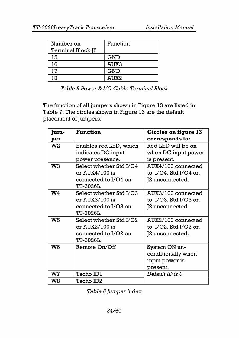
The J2 terminal block is labelled by pin function, as listed in Table 12.
Number on Terminal Block J2
Function
1 DC+ 2 DC- 3 3V3 out (3.3V) 4 GND 5 Std I/O 1 6 Std I/O 2 7 Std I/O 3 8 Std I/O 4 9 Std I/O 5 10 Std I/O 6 11 Remote On/Off 12 GND 13 GND 14 AUX4
TT-3026L easyTrack Transceiver Installation Manual
34/60
Number on Terminal Block J2
Function
15 GND 16 AUX3 17 GND 18 AUX2
Table 5 Power & I/O Cable Terminal Block
The function of all jumpers shown in Figure 13 are listed in Table 7. The circles shown in Figure 13 are the default placement of jumpers.
Jum-per
Function Circles on figure 13 corresponds to:
W2 Enables red LED, which indicates DC input power presence.
Red LED will be on when DC input power is present.
W3 Select whether Std I/O4 or AUX4/100 is connected to I/O4 on TT-3026L.
AUX4/100 connected to I/O4. Std I/O4 on J2 unconnected.
W4 Select whether Std I/O3 or AUX3/100 is connected to I/O3 on TT-3026L.
AUX3/100 connected to I/O3. Std I/O3 on J2 unconnected.
W5 Select whether Std I/O2 or AUX2/100 is connected to I/O2 on TT-3026L.
AUX2/100 connected to I/O2. Std I/O2 on J2 unconnected.
W6 Remote On/Off System ON un-conditionally when input power is present.
W7 Tacho ID1 Default ID is 0 W8 Tacho ID2
Table 6 Jumper index
TT-3026L easyTrack Transceiver Installation Manual
35/60
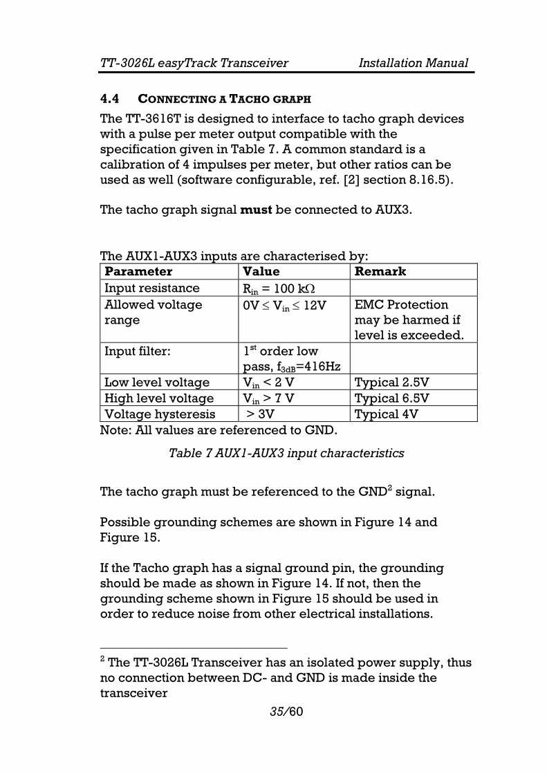
4.4 CONNECTING A TACHO GRAPH
The TT-3616T is designed to interface to tacho graph devices with a pulse per meter output compatible with the specification given in Table 7. A common standard is a calibration of 4 impulses per meter, but other ratios can be used as well (software configurable, ref. [2] section 8.16.5). The tacho graph signal must be connected to AUX3. The AUX1-AUX3 inputs are characterised by: Parameter Value Remark Input resistance Rin = 100 kΩ Allowed voltage range
0V ≤ Vin ≤ 12V EMC Protection may be harmed if level is exceeded.
Input filter: 1st order low pass, f3dB=416Hz
Low level voltage Vin < 2 V Typical 2.5V High level voltage Vin > 7 V Typical 6.5V Voltage hysteresis > 3V Typical 4V
Note: All values are referenced to GND.
Table 7 AUX1-AUX3 input characteristics
The tacho graph must be referenced to the GND2 signal. Possible grounding schemes are shown in Figure 14 and Figure 15. If the Tacho graph has a signal ground pin, the grounding should be made as shown in Figure 14. If not, then the grounding scheme shown in Figure 15 should be used in order to reduce noise from other electrical installations. 2 The TT-3026L Transceiver has an isolated power supply, thus no connection between DC- and GND is made inside the transceiver

TT-3026L easyTrack Transceiver Installation Manual
36/60
1 6 7 8 9 10 11 12 13 14 15 16 172 3 4 5 18
Signal
DC+DC-
fuse
Tachograph
TT-3616T Terminal Block (J2)
Signal Ground
Figure 15 Grounding scheme A

TT-3026L easyTrack Transceiver Installation Manual
37/60
1 6 7 8 9 10 11 12 13 14 15 16 172 3 4 5 18
Signal
DC+DC-
fuse
Tachograph
This signal Ground wire must be connected close to the Tachograph!
TT-3616T Terminal Block (J2)
Figure 16 Grounding scheme B

TT-3026L easyTrack Transceiver Installation Manual
38/60
4.5 TROUBLESHOOTING
Example: When the 4 Impulses/meter (4 Imp/m) output from tacho graph model MTCO 1324 (VDO) is correctly installed to the TT-3616T interconnection box, the signal measured on terminal block J2 between GND and AUX3 with an oscilloscope will look like Ch1 on Figure 16 (0-8.5V signal) when the vehicle is on the move.
Figure 17 Normal Tacho graph signal
The output from TT-3616T measured on terminal block J1 between GND and pin 9 will look like Ch2 on Figure 16 when the TT-3026L transceiver is correctly installed. This signal is basically the 4 Imp/m pulse divided by 100. In case the grounding is not performed correctly, the signal measured on terminal block J2 between GND and AUX3 might

TT-3026L easyTrack Transceiver Installation Manual
39/60
look like Ch1 in Figure 17. The corresponding signal with correct GND connection is shown in Figure 18.
Figure 18 Tacho graph signal with missing GND reference.
Figure 19 Tacho graph signal with correct GND reference.

TT-3026L easyTrack Transceiver Installation Manual
40/60
4.6 DTE CONNECTION VIA DB9 FEMALE CONNECTOR
An option for connection of a DTE is using the opt-944 Female 9-pole sub-D connector.
Figure 20 Sub-D with screw terminals
Wire colour in transceiver cable
Terminal no in sub-D connector
Function
Green 3 RD Black/Red 2 TD Violet 8 RTS Blue 7 CTS White 5 GND Cable shield Connector
housing GND
- 1 * DCD - 6 * DSR - 4 * DTR
Table 8 Sub-D wire connections
* Connect terminal 1, 4 & 6, as some applications need these connections to work properly. Also check out Remote On/Off (see section 4.2.2)

TT-3026L easyTrack Transceiver Installation Manual
41/60
4.7 TECHNICAL SPECIFICATION
Model TT-3026L
General Specifications Meets all INMARSAT specifications for the
Inmarsat mini-C Network for Land mobile and
Maritime terminals.
R&TTE
Transmit Frequency 1626.5 to 1660.5 MHz. note 1
Receive Frequency 1525.0 to 1559.0 MHz. note 1
Channel Spacing 5 / 2.5 / 1.25 kHz.
Modulation 1200 symbols/sec BPSK.
Ambiguity Resolution Unique word.
Coding R ½ K=7 convolutional code, (interleaved code
symbols RX).
Data Rate 600 bit/sec.
RX Frame Length 8.64 seconds.
TX Signalling Access Mode Slotted ALOHA.
TX Message Channel TDMA & FDMA, interleaved code symbols.
Terminal Interface EIA/TIA-232-E DTE interface. CCITT
Rec.V.24/28, 4800-115200 Baud IA-5 code
I/O Interface:
Six dedicated In/Out pins.
Open-collector. Sinks 25 mA each.
System Set-up S-RAM Battery backup
DC Power Source Floating DC
Nominal voltage range is 12V to 24V
Working voltage range is 10.5V to 32V
Max current 4A
Max power 32W
Power: RX: 1.8W ,TX: 23 W @ 12V supply
Fuse Self recovering Poly fuse
Ambient Temperature -35°C to 55°C operating
-40°C to 80°C storage.
Dimensions Ø=163 mm H: 143 mm
Weight 1.10 kg Note 1: Inmarsat-C frequencies: TX: 1626.5 – 1646.5 MHz RX: 1530 – 1545 MHz

TT-3026L easyTrack Transceiver Installation Manual
42/60
Operating system The TT-3026L easyTrack makes use of eCos™ operating
system.
Inmarsat-C
Protocol support
Message transmission and reception with IA-5, ITA-2 and
binary transfer to/from the following destinations:
Telex
PSTN (telephone modems and fax modems)
PSDN (X.25 network)
EGC message reception with automatic geographical area
selection.
Polling and data reporting with automatic transmission of
position reports down to a recommended minimum of 1 per 5
minutes.
Special Access Codes
DNID Messaging
Program Unreserved Data reporting
Transmit message size: Max 10Kbyte
Receive storage: > 32 Kbytes.
TT-3026L
easyTrack
Transceiver
Inmarsat-C/GPS omnidirectional antenna, RHC polarised.
G/T: -23.7 dB/K at 5° elevation
EIRP: 7 dBW dB at 5° elevation.
Temperature: -35°C to 55°C operating,
-40°C to 80°C storage.
Maximum
transmission
length
10 Kbytes.
Solar Radiation Max. flux density 1200W/m2.
Precipitation Up to 100 mm/hour, droplet size 0.5 to 4.5 mm
Ice Up to 25 mm.
Velocity Max velocity up to 140 km/hour (87mph).
Vibration
Operational
Random 5-20 Hz: 0.005 g2/Hz
20-150 Hz: -3dB/oct. (0.5g RMS).
Vibration Survival Random 5-20 Hz: 0.05 g2/Hz
20-150 Hz: -3dB/oct. (1.7g RMS).
Shock Half sine 20g/11ms
Table 9 TT-3026L Technical Spectifications

TT-3026L easyTrack Transceiver Installation Manual
43/60
5 SOFTWARE INSTALLATION
5.1 ABOUT EASYMAIL
EasyMail is a PC program, which can be used to control Thrane & Thrane Inmarsat-C transceivers. With easyMail you can easily send and receive e-mail, SMS, fax and telex messages, set up position reporting and many other things.
5.2 BEFORE YOU INSTALL
Before installation of easyMail make sure that your PC fulfils the following requirements: Operating system: Windows 98SE, 2000 or XP Free hard drive space: 10MByte minimum, 50MByte recommended.
5.3 EASYMAIL INSTALLATION
Follow these steps to install easyMail:
5.3.1 CD STARTUP
• Insert the easyMail installation CD in the CD drive of the PC. The setup program will start up automatically and the following window will be shown.

TT-3026L easyTrack Transceiver Installation Manual
44/60
If the program does not start automatically, run start.htm from your CD drive.
5.3.2 STARTING THE INSTALLATION
• Click ‘Install easyMail’.

TT-3026L easyTrack Transceiver Installation Manual
45/60
5.3.3 START UP WINDOW
• Click ‘Next’.
5.3.4 WELCOME SCREEN
• Click ‘Next’.

TT-3026L easyTrack Transceiver Installation Manual
46/60
5.3.5 DISCLAIMER WINDOW
• Read the disclaimer • Click the button ‘ I accept the terms in the license
agreement’ • Click ‘Next’
5.3.6 CUSTOMER INFORMATION

TT-3026L easyTrack Transceiver Installation Manual
47/60
• Type user name and organisation • Click ‘Next’.
5.3.7 DESTINATION FOLDER
• Choose destination folder (Default and recommended folder is C:\Program Files\easyMail)
• Click ‘Next’.

TT-3026L easyTrack Transceiver Installation Manual
48/60
5.3.8 READY TO INSTALL
• Click ‘Install’ to begin installing easyMail.
5.3.9 INSTALL COMPLETED
• Click ‘Finish’ to complete the installation procedure.

TT-3026L easyTrack Transceiver Installation Manual
49/60
5.3.10 STARTING EASYMAIL
• easyMail can be started in one of two ways:
1. Click the easyMail icon on the desktop. 2. Start easyMail from Start Programs Thrane &
Thrane easyMail 1.10 The easyMail main window below will be shown.
5.4 RUNNING EASYMAIL FOR THE FIRST TIME
When starting easyMail, for a moment the Connections and Mobile status field look like this:
TT-3026L easyTrack Transceiver Installation Manual
50/60
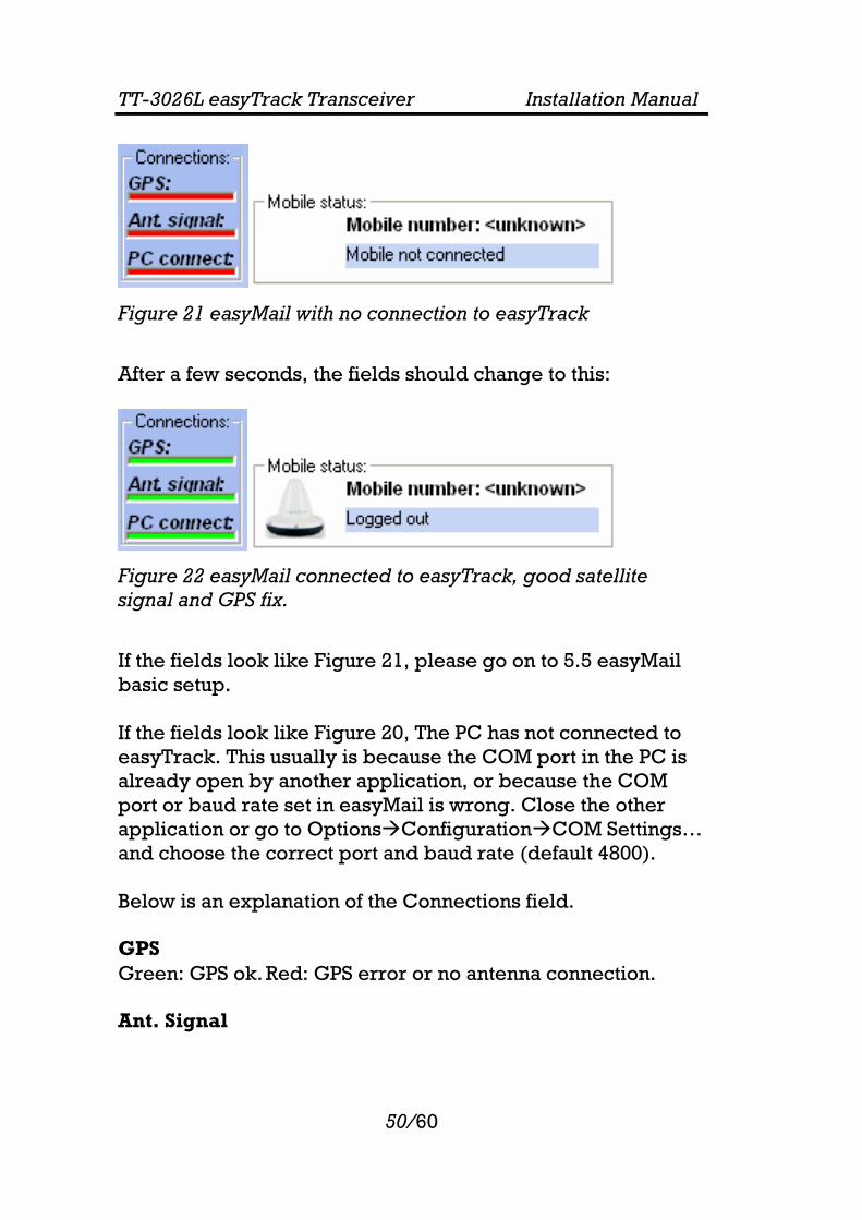
Figure 21 easyMail with no connection to easyTrack
After a few seconds, the fields should change to this:
Figure 22 easyMail connected to easyTrack, good satellite signal and GPS fix.
If the fields look like Figure 21, please go on to 5.5 easyMail basic setup. If the fields look like Figure 20, The PC has not connected to easyTrack. This usually is because the COM port in the PC is already open by another application, or because the COM port or baud rate set in easyMail is wrong. Close the other application or go to Options Configuration COM Settings… and choose the correct port and baud rate (default 4800). Below is an explanation of the Connections field. GPS Green: GPS ok. Red: GPS error or no antenna connection. Ant. Signal

TT-3026L easyTrack Transceiver Installation Manual
51/60
This bar has 5 steps from all green to all red, depending on the quality of the satellite signal. Green: good signal quality. Red: no signal. PC connect Green: easyMail has connected to easyTrack. Red: No connection between easyMail and easyTrack Please go on to the easyMail basic setup section, for a quick guide to getting easyTrack and easyMail configured and ready to use.
5.5 EASYMAIL BASIC SETUP
When starting easyMail for the first time, a few things need to be configured:
• Configure Mobile number. • Log in to an Ocean Region. • Default LES and E-mail Service Provider for sending
messages. Mobile number Click Options Configuration Mobile number. The following dialog is shown:
Type the Mobile number (9 digits) and click ‘Ok’. The Mobile number should be updated:

TT-3026L easyTrack Transceiver Installation Manual
52/60
Figure 23 Example of Mobile number
Log in to an Ocean Region
Figure 24 The login menu
Go to the menu Options Login and choose between the 4 Ocean Regions depending on your current position. After a short while the Mobile status field has changed:
Figure 25 Example when logged in to East Atlantic
You have now logged in to the Inmarsat satellite network. Default LES and E-mail Service Provider for sending messages. To set up easyMail for sending messages, the following needs to be configured.

TT-3026L easyTrack Transceiver Installation Manual
53/60
Click Options Set Default ISP…
Figure 26 Choose your Service Provider
Choose your Inmarsat Service Provider on the list. Click ‘Options Set Default LES…’
Figure 27 Land Earth Stations (LESs) of your Inmarsat Service Provider
Choose the Land Earth Stations of your Inmarsat Service Provider for each Ocean Region. You are now ready to send and receive messages.
5.6 GETTING NEW VERSIONS OF EASYMAIL
easyMail is a free program and can be downloaded on the Thrane & Thrane website on the following address: http://www.thrane.com/
TT-3026L easyTrack Transceiver Installation Manual
54/60
6 TEST OF THE SYSTEM
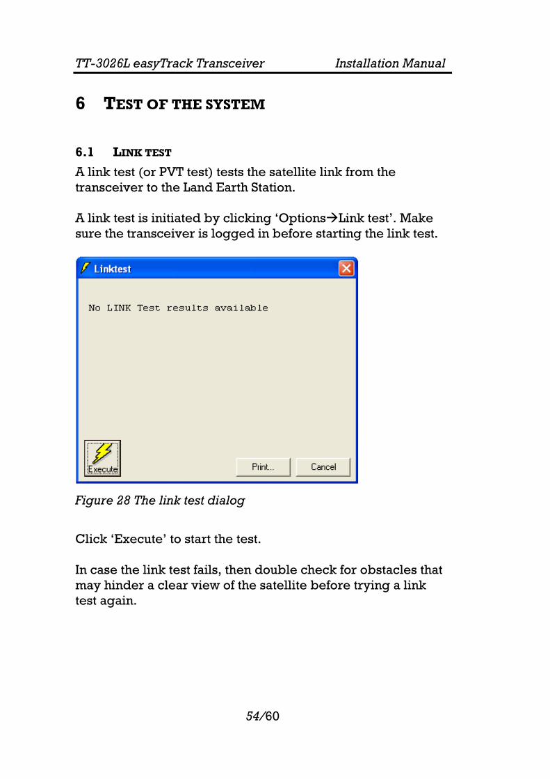
6.1 LINK TEST
A link test (or PVT test) tests the satellite link from the transceiver to the Land Earth Station. A link test is initiated by clicking ‘Options Link test’. Make sure the transceiver is logged in before starting the link test.
Figure 28 The link test dialog
Click ‘Execute’ to start the test. In case the link test fails, then double check for obstacles that may hinder a clear view of the satellite before trying a link test again.

TT-3026L easyTrack Transceiver Installation Manual
55/60
7 MAINTENANCE GUIDELINES When properly installed the TT-3026L needs no maintenance. After approximately 10 years an internal battery has to be replaced, and the transceiver must be sent for service. Low battery level will result in loss of configuration data in case the unit is powered down.
7.1 HANDLING PRECAUTIONS
• Do not expose the transceiver’s parting line (the blue styling gasket) & connector to high-pressure water jets.
• Exposure of chemical containing alkalis may result in physical degradation of the transceiver.
• Do not expose the transceiver to acid curing silicone. • Avoid contact with solvents.
Do not paint the transceiver. If it is absolutely necessary to paint the transceiver, ideally water-based paints or paint system based on mild solvents should be selected.

TT-3026L easyTrack Transceiver Installation Manual
56/60
8 APPENDIX A
8.1 MOUNTING STENCIL
Figure 29 Mounting stencil
For connector: predrilled hole 32mm (1.26”) diameter A: 3 x predrilled holes 5mm (0.2”) diameter for M4 screws.

TT-3026L easyTrack Transceiver Installation Manual
57/60
9 APPENDIX B
9.1 INTERCONNECTION BOX TT-3616B
For connecting the TT-3026L easyTrack to peripheral equipment without tacho graph input, the TT-3616B interconnection box can be used. It includes proper connectors for DTE (Data Terminal Equipment), I/O ports (remote transducers, alarm button), on/off wire and power supply. The interconnection box also includes an amplification/buffer of the RS232 signals.
Figure 30 TT-3616B Interconnection box
TT-3026L easyTrack Transceiver Installation Manual
58/60
1 18
1 12
Powerconnector
IndicatorLEDs
Power & I/O CableAccess Ports
Power & I/O CableStrain Relief Points
DB9 Connector forData Terminal
Equipment
Transceiver CableAccess Port
Transceiver CableStrain Relief Points
Transceiver CableTerminal Block (J1)
Power & I/O CableTerminal Block (J2)
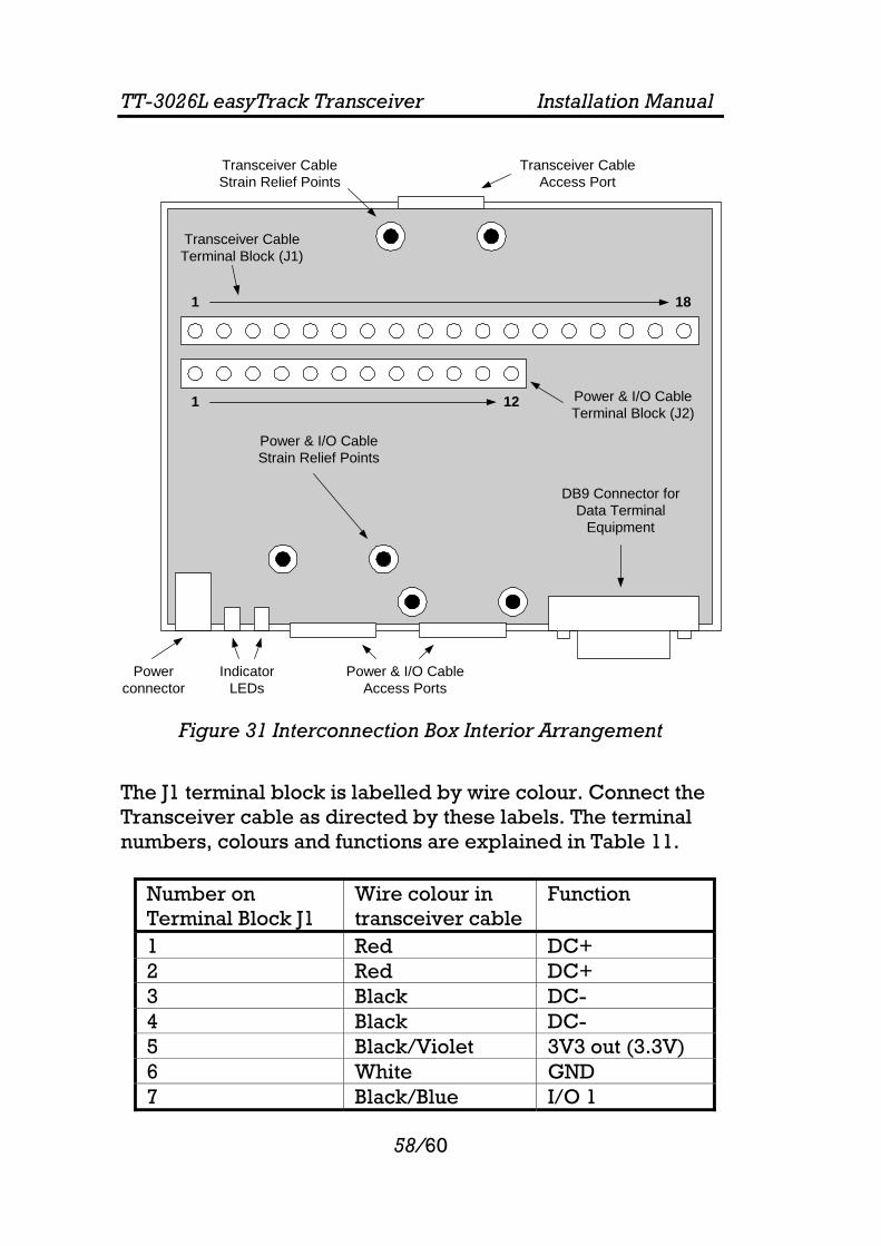
Figure 31 Interconnection Box Interior Arrangement
The J1 terminal block is labelled by wire colour. Connect the Transceiver cable as directed by these labels. The terminal numbers, colours and functions are explained in Table 11.
Number on Terminal Block J1
Wire colour in transceiver cable
Function
1 Red DC+ 2 Red DC+ 3 Black DC- 4 Black DC- 5 Black/Violet 3V3 out (3.3V) 6 White GND 7 Black/Blue I/O 1

TT-3026L easyTrack Transceiver Installation Manual
59/60
Number on Terminal Block J1
Wire colour in transceiver cable
Function
8 Grey I/O 2 9 Black/Yellow I/O 3 10 Black/Grey I/O 4 11 Brown I/O 5 12 Black/Green I/O 6 13 Yellow Remote On/Off 14 Orange GND 15 Blue CTS * 16 Violet RTS * 17 Green RD * 18 Black/Red TD * Stain relief Bracket Cable shield GND
Table 10 Transceiver Cable Terminal Block
* DCE naming Remote On/Off is explained in section 4.2.2. The DB9 Connector is connected to Data Terminal Equipment using a std. DB9 to DB9 Modem cable. The J2 terminal block is labelled by pin function, as listed in Tabel 12.
Number on Terminal Block J2 Function 1 DC+ 2 DC- 3 3V3 out (3.3V) 4 GND 5 I/O 1 6 I/O 2 7 I/O 3 8 I/O 4 9 I/O 5 10 I/O 6 11 Remote On/Off

TT-3026L easyTrack Transceiver Installation Manual
60/60
Number on Terminal Block J2 Function 12 GND
Table 11 Power & I/O Cable Terminal Block
Jumper W2 enables LED 1, which indicates DC in. +++