Thrane IP Handset - sailsatellite.com
150
Thrane IP Handset User manual
Transcript of Thrane IP Handset - sailsatellite.com
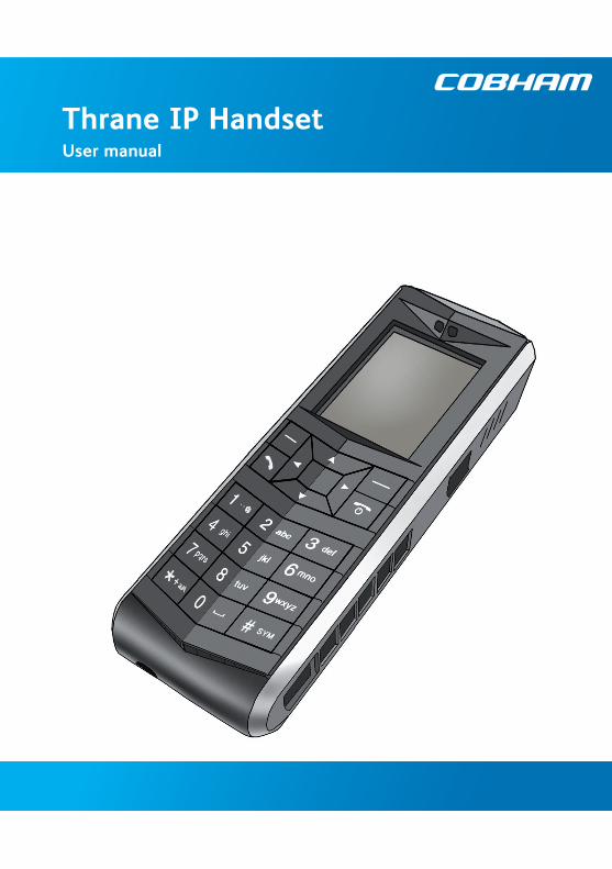
Thrane IP HandsetUser manual

Thrane IP Handset
User Manual
Document number: 98-126059-I
Release date: July 17, 2013
i
Disclaimer
Any responsibility or liability for loss or damage in connection with the use of this product and the accompanying documentation is disclaimed by Thrane & Thrane. The information in this manual is provided for information purposes only, is subject to change without notice and may contain errors or inaccuracies. Manuals issued by Thrane & Thrane are periodically revised and updated. Anyone relying on this information should acquire the most current version e.g. from cobham.com/satcom or from the distributor. Thrane & Thrane is not responsible for the content or accuracy of any translations or reproductions, in whole or in part, of this manual from any other source.
Thrane & Thrane A/S trading as Cobham SATCOM.
Copyright © 2013 Thrane & Thrane A/S. All rights reserved.
Trademark Acknowledgements:
• Thrane & Thrane is a registered trademark of Thrane & Thrane A/S in the European Union and the United States.
• Inmarsat is a registered trademark of the International Maritime Satellite Organisation (IMSO) and is licensed by IMSO to Inmarsat Limited and Inmarsat Ventures plc.
• Inmarsat’s product names are trademarks or registered trademarks of Inmarsat.
• Other product and company names mentioned in this manual may be trademarks or trade names of their respective owners.
ii
Safety Summary
The following general safety precautions must be observed during all phases of operation, service and repair of this equipment. Failure to comply with these precautions or with specific warnings elsewhere in this manual violates safety standards of design, manufacture and intended use of the equipment. Thrane & Thrane A/S assumes no liability for the customer's failure to comply with these requirements.
DO NOT OPERATE IN AN EXPLOSIVE ATMOSPHERE
Do not operate the IP Handset in the presence of flammable gases or fumes. Operation of any electrical equipment in such an environment constitutes a definite safety hazard.
KEEP AWAY FROM LIVE CIRCUITS
Operating personnel must not remove equipment covers. Component replacement and internal adjustment must be made by qualified maintenance personnel. Do not replace components with the cable connected. Always disconnect power and discharge circuits before touching them.
DISPOSAL
Old electrical and electronic equipment marked with this symbol can contain substances hazardous to human beings and the environment. Never dispose these items together with unsorted municipal waste (household waste). In order to protect the environment and ensure the correct recycling of old equipment as well as the re-utilization of individual components, use either public collection or private collection by the local distributor of old electrical and electronic equipment marked with this symbol.
Contact the local distributor for information about what type of return system to use.
iii
About the Manual
Intended readers
This manual is a user manual for the Thrane IP Handset. The readers of the manual include anyone who is using or intends to use the IP Handset. No specific skills are required to operate the IP Handset. However, it is important that you observe all safety requirements listed in the beginning of this manual, and operate the handset according to the guidelines in this manual.
Manual overview
This manual has the following chapters:
• Introduction contains an overview and a brief description of the IP Handset.
• Getting started explains how to connect and start up the handset and gives an overview of the display and keypad. It also contains a short guide to initial configuration and to making the first call.
• Using the IP Handset describes how to use and configure the handset and explains the display menus.
• Using the web server explains how to use the built-in web server of the IP Handset.
• Service & maintenance contains guidelines for maintenance of the handset, a short troubleshooting guide and gives information on where to get further help if needed.
This manual may not always reflect the latest software functionality of your IP Handset. To obtain the latest version of the manual, please enter the Thrane & Thrane Extranet and download the latest version, or acquire it from your distributor.
iv
Typography
In this manual, typography is used as indicated below:
Bold is used for the following purposes:
• To emphasize words. Example: “Do not touch the antenna”.
• To indicate what the user should select in the user interface. Example: “Select Settings > Display”.
Italic is used to emphasize the paragraph title in cross-references.
Example: “For further information, see Connecting Cables on page...”.
Related documents
The following related documentation is referred to in this manual:
TitleDocument number
Voice Distress (Non-SOLAS) User manual 98-133687
v

vi
Table of Contents
Safety Summary .............................................................................. iii
About the Manual .......................................................................... iv
Chapter 1 Introduction
Welcome ................................................................................................... 1
Your IP Handset ..................................................................................... 1Description ................................................................................................. 1The wired IP Handset ............................................................................. 3The wireless IP Handset ......................................................................... 4
Features ..................................................................................................... 5
Chapter 2 Getting started
Getting started with the wired IP Handset ............................... 7Introduction .............................................................................................. 7Connectors on the wired handset ...................................................... 8Connecting the cables to the IP cradle ............................................. 8Installing the cradle .............................................................................. 10Connecting the wired IP Handset to a BGAN terminal ............. 11Starting up the wired IP Handset ..................................................... 12
Getting started with the wireless IP Handset ....................... 13Introduction ........................................................................................... 13Preparing the hardware ....................................................................... 14Charging the IP Handset ..................................................................... 17Connecting the IP Handset to a wireless access point .............. 19
Establishing a connection using BGAN terminal ................ 20Using a BGAN terminal ........................................................................ 20Establishing a connection ................................................................... 20Changing user name and password for an IP Handset .............. 23
Making the first call ........................................................................ 25
vii
Table of Contents
IP Handset keypad and display ................................................... 26The keypad ............................................................................................. 26The display .............................................................................................. 32
Chapter 3 Using the IP Handset
User interfaces .................................................................................... 37
IP Handset functions ....................................................................... 38Handling calls ......................................................................................... 38Making a call using a BGAN terminal .............................................. 46Using the IP Handset for Voice Distress ........................................ 47Making a secure call from the IP Handset ..................................... 47Quick settings ......................................................................................... 52How to enter text in the IP Handset ............................................... 54Using a headset ..................................................................................... 55
IP Handset menus ............................................................................. 56Call log ...................................................................................................... 57Contacts ................................................................................................... 59Status ........................................................................................................ 61Network ................................................................................................... 62Settings .................................................................................................... 68SIP telephony and profiles ................................................................. 79Information from the BGAN terminal ............................................ 85
Chapter 4 Using the web server
Introduction to the web server ................................................... 91Browser settings .................................................................................... 92
Using the web server ....................................................................... 95The Home page ..................................................................................... 95Contacts ................................................................................................... 96Call log ...................................................................................................... 97SIP settings ............................................................................................. 98Uploading firmware ........................................................................... 100Import and Export settings ............................................................. 101Help and diagnostics report ............................................................ 103
viii
Table of Contents
Chapter 5 Service & maintenance
Getting support ............................................................................... 105
Maintenance tasks ......................................................................... 106Software update ................................................................................. 106Battery handling for the wireless IP Handset ............................ 106Cleaning the IP Handset .................................................................. 107Disposal of the IP Handset .............................................................. 107
Troubleshooting guide ................................................................. 110
App. A Technical specifications
Thrane IP Handset, wired ............................................................ 111Specifications, wired handset ........................................................ 111Outline dimensions, wired handset .............................................. 113
Thrane IP Handset, wireless ....................................................... 115Specifications, wireless handset .................................................... 115Outline dimensions, wireless handset .......................................... 117
Thrane IP cradle outline dimensions ..................................... 119
App. B Conformity
Thrane IP Handset, wired ............................................................ 121CE (LVD & EMC) .................................................................................. 121FCC ......................................................................................................... 121
Thrane IP Handset, wireless ....................................................... 123CE (R&TTE) ........................................................................................... 123FCC ......................................................................................................... 123FCC/IC Notice ..................................................................................... 125
Glossary .................................................................................................................. 127
Index .................................................................................................................. 131
ix

Table of Contents
x

Chapter 11111
Intr
oduc
tion
Introduction 1
Welcome
Congratulations on the purchase of your IP Handset!
The IP Handset communicates using Voice over Internet Protocol (VoIP), which means that voice conversations are routed over the Internet or through an IP-based network.
Your IP Handset
Description
The IP Handset is used for making phone calls over an IP based network.
The IP Handset has some BGAN terminal control functions. If configured as handset with the local number 0501, you can use the handset to start and stop data connections (background or streaming) for all network user groups.
To improve overall system overview the IP Handset displays active, critical alarms from the BGAN terminal to keep you informed about the status of the BGAN terminal.
The handset is designed specifically for use in harsh environments and it is dust proof and splash proof. Excellent sound quality is achieved by including an efficient noise
1
Chapter 1: Introduction
suppression software. On the large 2.2" colour TFT screen, a graphical user interface provides easy access to all functions including contacts and settings. The user interface also provides direct access to certain features of a connected BGAN terminal.
There are two variants of the handset: A wired model and a wireless model.
When used with a BGAN terminal and a SAILOR 3771 Alarm Panel, the IP Handset can be used as a designated handset for Voice Distress and urgency calls.
You can make secure calls to all IP phones complying with the ZRTP version used by the IP Handset.
2 Your IP Handset
Chapter 1: Introduction1111
Intr
oduc
tion
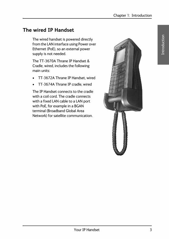
The wired IP Handset
The wired handset is powered directly from the LAN interface using Power over Ethernet (PoE), so an external power supply is not needed.
The TT-3670A Thrane IP Handset & Cradle, wired, includes the following main units:
• TT-3672A Thrane IP Handset, wired
• TT-3674A Thrane IP cradle, wired
The IP Handset connects to the cradle with a coil cord. The cradle connects with a fixed LAN cable to a LAN port with PoE, for example in a BGAN terminal (Broadband Global Area Network) for satellite communication.
Your IP Handset 3
Chapter 1: Introduction
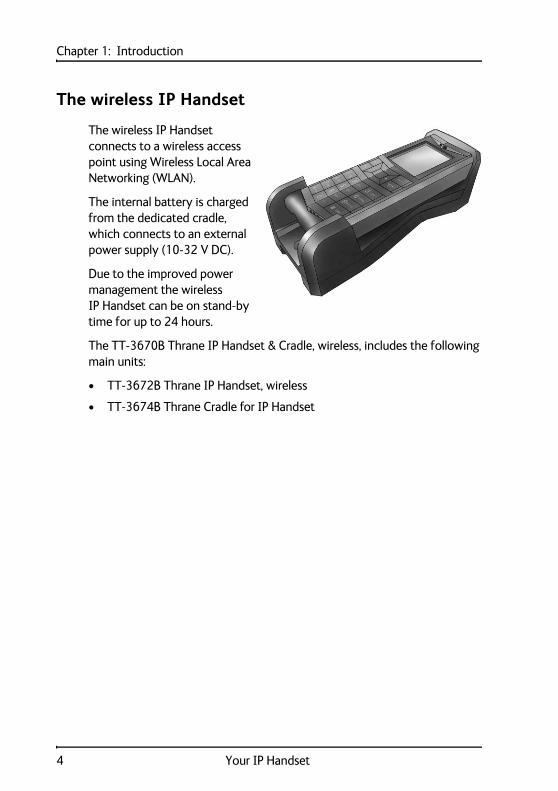
The wireless IP Handset
The wireless IP Handset connects to a wireless access point using Wireless Local Area Networking (WLAN).
The internal battery is charged from the dedicated cradle, which connects to an external power supply (10-32 V DC).
Due to the improved power management the wireless IP Handset can be on stand-by time for up to 24 hours.
The TT-3670B Thrane IP Handset & Cradle, wireless, includes the following main units:
• TT-3672B Thrane IP Handset, wireless
• TT-3674B Thrane Cradle for IP Handset
4 Your IP Handset
Chapter 1: Introduction1111
Intr
oduc
tion
Features
The IP Handset offers the following features:
Plain voice communication over Internet or IP based network
Secure voice communication over Internet or IP based network
Start and stop IP data connections in a connected BGAN terminal
Contacts list with up to 100 entries
Intuitive user interface and menu system
Built-in web server
High quality colour display QVGA with night colours
Rugged but elegant design
Splash proof and dust proof
Connectivity to Broadband Global Area Network (BGAN) terminal
BGAN menu to display BGAN terminal type, GPS position and more
Display of critical alarms from the BGAN terminal
Use as Distress IP Handset together with BGAN terminal and SAILOR 3771 Alarm Panel
Features 5

Chapter 1: Introduction
6 Features
Chapter 222
22
Get
ting
sta
rted
Getting started 2
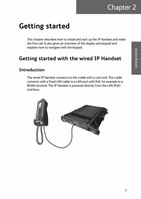
This chapter describes how to install and start up the IP Handset and make the first call. It also gives an overview of the display and keypad and explains how to navigate with the keypad.
Getting started with the wired IP Handset
Introduction
The wired IP Handset connects to the cradle with a coil cord. The cradle connects with a fixed LAN cable to a LAN port with PoE, for example in a BGAN terminal. The IP Handset is powered directly from the LAN (PoE) interface.
7
Chapter 2: Getting started
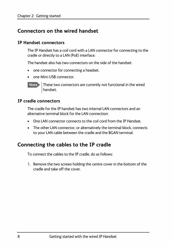
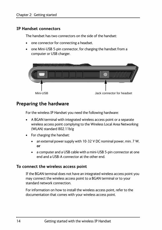
Connectors on the wired handset
IP Handset connectors
The IP Handset has a coil cord with a LAN connector for connecting to the cradle or directly to a LAN (PoE) interface.
The handset also has two connectors on the side of the handset:
• one connector for connecting a headset.
• one Mini-USB connector.
IP cradle connectors
The cradle for the IP handset has two internal LAN connectors and an alternative terminal block for the LAN connection:
• One LAN connector connects to the coil cord from the IP Handset.
• The other LAN connector, or alternatively the terminal block, connects to your LAN cable between the cradle and the BGAN terminal.
Connecting the cables to the IP cradle
To connect the cables to the IP cradle, do as follows:
1. Remove the two screws holding the centre cover in the bottom of the cradle and take off the cover.
Note These two connectors are currently not functional in the wired handset.
8 Getting started with the wired IP Handset
Chapter 2: Getting started2
22
2
Get
ting
sta
rted
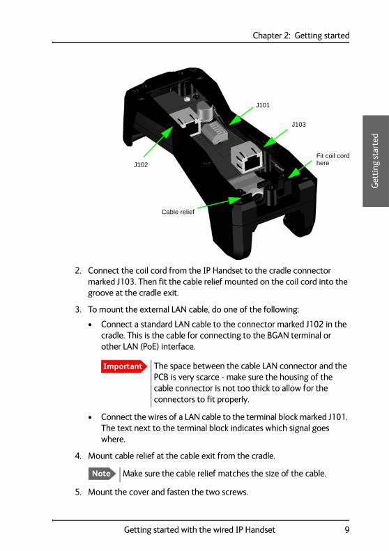
2. Connect the coil cord from the IP Handset to the cradle connector marked J103. Then fit the cable relief mounted on the coil cord into the groove at the cradle exit.
3. To mount the external LAN cable, do one of the following:
• Connect a standard LAN cable to the connector marked J102 in the cradle. This is the cable for connecting to the BGAN terminal or other LAN (PoE) interface.
• Connect the wires of a LAN cable to the terminal block marked J101. The text next to the terminal block indicates which signal goes where.
4. Mount cable relief at the cable exit from the cradle.
5. Mount the cover and fasten the two screws.
Important The space between the cable LAN connector and the PCB is very scarce - make sure the housing of the cable connector is not too thick to allow for the connectors to fit properly.
Note Make sure the cable relief matches the size of the cable.
J101
J102
Cable relief
J103
Fit coil cordhere
Getting started with the wired IP Handset 9
Chapter 2: Getting started
Installing the cradle
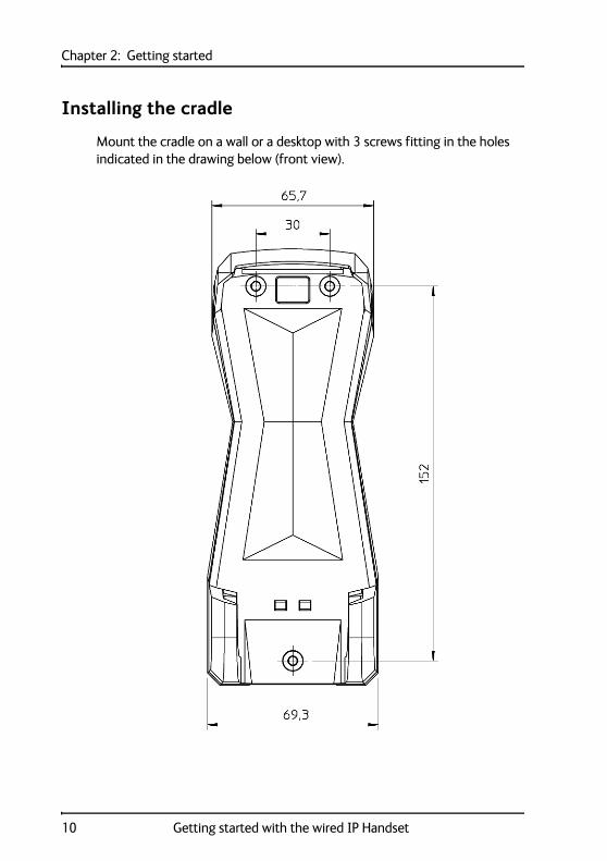
Mount the cradle on a wall or a desktop with 3 screws fitting in the holes indicated in the drawing below (front view).
10 Getting started with the wired IP Handset

Chapter 2: Getting started2
22
2
Get
ting
sta
rted
Connecting the wired IP Handset to a BGAN terminal
To connect the wired IP Handset to a BGAN terminal do as follows:
1. Start up the BGAN terminal as described in the user manual for the terminal.
2. Connect the LAN cable from the IP cradle to one of the LAN (PoE) connectors on the BGAN terminal.
The cable between cradle and terminal must be maximum 80 m.
The IP Handset starts up automatically when connected to the BGAN terminal. However, you may have to configure user name and password if the handset has not been connected before, and if it is not set up to automatically connect with the SIP server of the terminal. For further information, see Establishing a connection using BGAN terminal on page 20.
Note The LAN interface on the BGAN terminal must supply Power over Ethernet.
Note If you insert a switch or similar between the cradle and the terminal, make sure that it conforms to the industry PoE standard IEEE 802.3 af (using data pairs).
Getting started with the wired IP Handset 11
Chapter 2: Getting started
Starting up the wired IP Handset
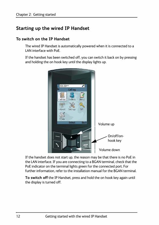
To switch on the IP Handset
The wired IP Handset is automatically powered when it is connected to a LAN interface with PoE.
If the handset has been switched off, you can switch it back on by pressing and holding the on hook key until the display lights up.
If the handset does not start up, the reason may be that there is no PoE in the LAN interface. If you are connecting to a BGAN terminal, check that the PoE indicator on the terminal lights green for the connected port. For further information, refer to the installation manual for the BGAN terminal.
To switch off the IP Handset, press and hold the on hook key again until the display is turned off.
On/off/on-hook key
Volume up
Volume down
12 Getting started with the wired IP Handset
Chapter 2: Getting started2
22
2
Get
ting
sta
rted
Getting started with the wireless IP Handset
Introduction
Overview
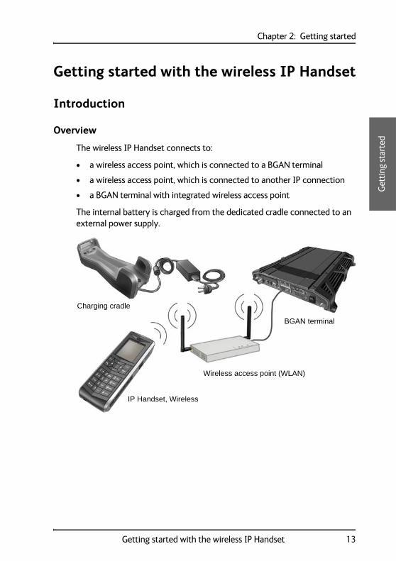
The wireless IP Handset connects to:
• a wireless access point, which is connected to a BGAN terminal
• a wireless access point, which is connected to another IP connection
• a BGAN terminal with integrated wireless access point
The internal battery is charged from the dedicated cradle connected to an external power supply.
Charging cradle
IP Handset, Wireless
Wireless access point (WLAN)
BGAN terminal
Getting started with the wireless IP Handset 13
Chapter 2: Getting started
IP Handset connectors
The handset has two connectors on the side of the handset:
• one connector for connecting a headset.
• one Mini-USB 5-pin connector, for charging the handset from a computer or USB charger.
Preparing the hardware
For the wireless IP Handset you need the following hardware:
• A BGAN terminal with integrated wireless access point or a separate wireless access point complying to the Wireless Local Area Networking (WLAN) standard 802.11b/g
• For charging the handset:
• an external power supply with 10-32 V DC nominal power, min. 7 W, or
• a computer and a USB cable with a mini-USB 5-pin connector at one end and a USB-A connector at the other end.
To connect the wireless access point
If the BGAN terminal does not have an integrated wireless access point you may connect the wireless access point to a BGAN terminal or to your standard network connection.
For information on how to install the wireless access point, refer to the documentation that comes with your wireless access point.
Mini-USB Jack connector for headset
14 Getting started with the wireless IP Handset
Chapter 2: Getting started2
22
2
Get
ting
sta
rted
To connect an external power supply to the cradle
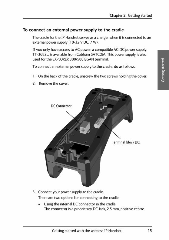
The cradle for the IP Handset serves as a charger when it is connected to an external power supply (10-32 V DC, 7 W).
If you only have access to AC power, a compatible AC-DC power supply, TT-3682L, is available from Cobham SATCOM. This power supply is also used for the EXPLORER 300/500 BGAN terminal.
To connect an external power supply to the cradle, do as follows:
1. On the back of the cradle, unscrew the two screws holding the cover.
2. Remove the cover.
3. Connect your power supply to the cradle.
There are two options for connecting to the cradle:
• Using the internal DC connector in the cradle. The connector is a proprietary DC Jack, 2.5 mm, positive centre.
Terminal block J101
DC Connector
Getting started with the wireless IP Handset 15
Chapter 2: Getting started
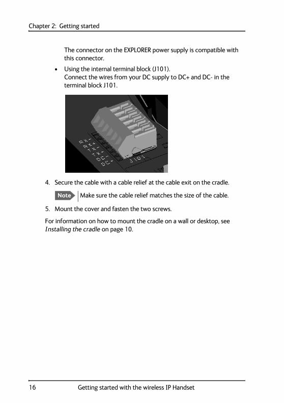
The connector on the EXPLORER power supply is compatible with this connector.
• Using the internal terminal block (J101).Connect the wires from your DC supply to DC+ and DC- in the terminal block J101.
4. Secure the cable with a cable relief at the cable exit on the cradle.
5. Mount the cover and fasten the two screws.
For information on how to mount the cradle on a wall or desktop, see Installing the cradle on page 10.
Note Make sure the cable relief matches the size of the cable.
16 Getting started with the wireless IP Handset
Chapter 2: Getting started2
22
2
Get
ting
sta
rted
Charging the IP Handset
Introduction
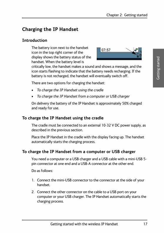
The battery icon next to the handset icon in the top right corner of the display shows the battery status of the handset. When the battery level is critically low, the handset makes a sound and shows a message, and the icon starts flashing to indicate that the battery needs recharging. If the battery is not recharged, the handset will eventually switch off.
There are two options for charging the handset:
• To charge the IP Handset using the cradle
• To charge the IP Handset from a computer or USB charger
On delivery the battery of the IP Handset is approximately 50% charged and ready for use.
To charge the IP Handset using the cradle
The cradle must be connected to an external 10-32 V DC power supply, as described in the previous section.
Place the IP Handset in the cradle with the display facing up. The handset automatically starts the charging process.
To charge the IP Handset from a computer or USB charger
You need a computer or a USB charger and a USB cable with a mini-USB 5-pin connector at one end and a USB-A connector at the other end.
Do as follows:
1. Connect the mini-USB connector to the connector at the side of your handset.
2. Connect the other connector on the cable to a USB port on your computer or your USB charger. The IP Handset automatically starts the charging process.
Getting started with the wireless IP Handset 17
Chapter 2: Getting started
Indications during charging process
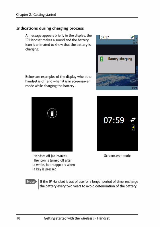
A message appears briefly in the display, the IP Handset makes a sound and the battery icon is animated to show that the battery is charging.
Below are examples of the display when the handset is off and when it is in screensaver mode while charging the battery.
Note If the IP Handset is out of use for a longer period of time, recharge the battery every two years to avoid deterioration of the battery.
Handset off (animated). Screensaver modeThe icon is turned off aftera while, but reappears whena key is pressed.
18 Getting started with the wireless IP Handset
Chapter 2: Getting started2
22
2
Get
ting
sta
rted
Connecting the IP Handset to a wireless access point
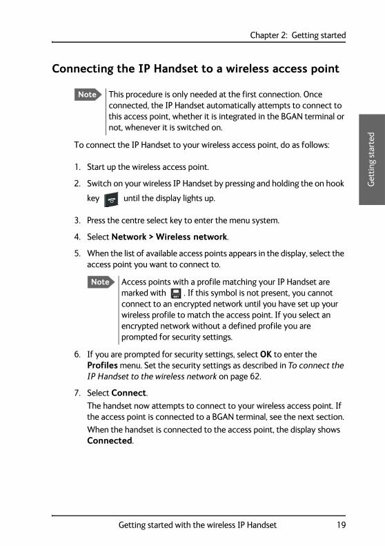
To connect the IP Handset to your wireless access point, do as follows:
1. Start up the wireless access point.
2. Switch on your wireless IP Handset by pressing and holding the on hook
key until the display lights up.
3. Press the centre select key to enter the menu system.
4. Select Network > Wireless network.
5. When the list of available access points appears in the display, select the access point you want to connect to.
6. If you are prompted for security settings, select OK to enter the Profiles menu. Set the security settings as described in To connect the IP Handset to the wireless network on page 62.
7. Select Connect.
The handset now attempts to connect to your wireless access point. If the access point is connected to a BGAN terminal, see the next section.
When the handset is connected to the access point, the display shows Connected.
Note This procedure is only needed at the first connection. Once connected, the IP Handset automatically attempts to connect to this access point, whether it is integrated in the BGAN terminal or not, whenever it is switched on.
Note Access points with a profile matching your IP Handset are marked with . If this symbol is not present, you cannot connect to an encrypted network until you have set up your wireless profile to match the access point. If you select an encrypted network without a defined profile you are prompted for security settings.
Getting started with the wireless IP Handset 19
Chapter 2: Getting started
Establishing a connection using BGAN terminal
Using a BGAN terminal
Introduction
By connecting the IP Handset to a BGAN terminal you gain access to the BGAN satellite network with your IP Handset.
When connected with the BGAN terminal the IP Handset provides a dedicated menu for the terminal.
IP Handset connection
The wired handset is connected to the BGAN terminal by connecting the Ethernet cable from the cradle to one of the LAN ports of the terminal. For further information, see Connecting the wired IP Handset to a BGAN terminal on page 11.
The wireless handset is connected to the BGAN terminal either by connecting to the integrated wireless access point of the terminal or to a separate wireless access point connected to one of the LAN ports of the terminal. For information on how to connect the handset to the access point, see Connecting the IP Handset to a wireless access point on page 19.
Establishing a connection
When the handset is connected to the BGAN terminal, it is automatically registered in the terminal and assigned the first available local number, if the startup option Auto BGAN SIP is selected. If, for some reason, you need another password or local number, you need to set up the following in the handset and in the web interface of the BGAN terminal (the startup option Auto BGAN SIP must be disabled!):
• User name
• Password
20 Establishing a connection using BGAN terminal
Chapter 2: Getting started2
22
2
Get
ting
sta
rted
• Local number
For further information, see Changing user name and password for an IP Handset on page 23.
If no SIM PIN is required
If the IP Handset is connected to a BGAN terminal where the SIM PIN is disabled or has already been entered, the BGAN terminal automatically sets up a communication profile (SIP profile) and assigns the first available local number to the handset, if the startup option Auto BGAN SIP is enabled.
If a SIM PIN is required
If the IP Handset is connected to a BGAN terminal where the SIM PIN is required and has not yet been entered, you need to enter the SIM PIN for the terminal. To do so, you need to know the Administrator user name and password as well as the SIM PIN for the BGAN terminal.
To enter the BGAN terminal’s SIM PIN, do as follows:
1. From the main screen of the handset, press the centre select key to enter the menu system.
2. Select BGAN.
3. Select Enter PIN code.
4. Enter the Administrator user name and select OK.
For information on how to type text in the handset, see How to enter text in the IP Handset on page 54.
Note There may be 2 PIN codes for the system:
• one for the BGAN terminal (SIM PIN, described in this section) and
• one for the IP Handset (described in To set up the PIN code for the handset on page 76)
Note This menu item is not available if the PIN has already been accepted. You can check at Status > PIN status to see if the PIN has been accepted.
Establishing a connection using BGAN terminal 21
Chapter 2: Getting started
5. Enter the Administrator password and select OK.
6. Enter the SIM PIN and select OK.If the SIM PIN is rejected, see the next section Wrong PIN.
When the PIN is accepted, the BGAN terminal automatically sets up a SIP profile and assigns the first available local number to the handset, if the startup option Auto BGAN SIP is enabled.
Wrong PIN
After entering the user name and password, you have 3 attempts to enter the PIN, before you are asked to enter the PUK (Pin Unblocking Key). The PUK is supplied with your BGAN SIM card. Enter the PUK followed by a new PIN of your own choice. The PIN must be from 4 to 8 digits long.
IP Handset ready
When the display shows the handset ready symbol in the upper right corner, the handset is ready for making a call.
If the handset ready symbol is crossed out you cannot make a call. The display will normally show a message explaining why the handset is not ready.
Caution! If you enter a wrong PUK 10 times, the SIM card will no longer be functional, and you have to contact your Airtime Provider for a new SIM card.
22 Establishing a connection using BGAN terminal
Chapter 2: Getting started2
22
2
Get
ting
sta
rted
Changing user name and password for an IP Handset
If the startup option Auto BGAN SIP is selected, an IP Handset that is connected to the terminal automatically gets the first available user name (local number) and password. If you want to change the user name or password, you need to set up the user name, password and local number in two places:
• In the IP Handset
• In the web interface of the BGAN terminal.
To enter user name and password in the IP Handset
To enter the user name and password in the IP Handset, do as follows:
1. Start up the handset as described in the previous sections.
2. Enter the menu system and select SIP.
3. Move to the BGAN profile and select Options (left select key).
4. Select Edit/View.
5. Select User name and enter the user name for your handset. Note that the user name must be the same as the local number for your handset when using the BGAN terminal. Available numbers are 0501 to 0516.
6. Select Password and enter the password for your handset. Note this password for later use in the terminal. You can use the local number as the password as well, i.e. 0501 to 0516.
7. Exit the menu.
Note Make sure you have disabled Auto BGAN SIP under Settings > Startup options. Otherwise the information entered below is not used at next startup!
Note The Thrane IP Handset only supports numbers (no letters) in the password.
Establishing a connection using BGAN terminal 23

Chapter 2: Getting started
To enter user name and password in the BGAN terminal
To match the IP Handset with the BGAN terminal you must enter the local number and password for each IP Handset in the web interface of the BGAN terminal.
To set up the BGAN terminal, do as follows:
1. Connect a computer to the LAN interface of the BGAN terminal and start up your browser.
2. In the address bar, enter ut.bgan or the IP address for the BGAN terminal. The default IP address is 192.168.0.1.
The web interface opens.
3. Select SETTINGS > IP handsets.
4. Locate the local number that matches the user name (local number) of your handset and click Edit.
5. Enter the same password you entered in the handset.
When the terminal and the handset have recognized each other, a Configure link appears next to the new handset in the web interface of the terminal. Click the Configure link to open the internal web server of the IP Handset. For information on the web server, see Using the web server on page 91.
24 Establishing a connection using BGAN terminal
Chapter 2: Getting started2
22
2
Get
ting
sta
rted
Making the first call
To make a call, do as follows:
1. Type the phone number on the keypad.
If the number is in the Contacts list of the handset, you can also select the number from there.
2. Press the off hook key in the left side of
the keypad or press #.
The display shows that the number is being dialled.
3. Volume up or down: If you need to adjust the voice volume during a call and the display shows the main screen, press or on the keypad.
For further information on how to make calls, see Handling calls on page 38.
For a detailed description how to make secure calls see Making a secure call from the IP Handset on page 47.
Making the first call 25
Chapter 2: Getting started
IP Handset keypad and display
The keypad
The following drawing shows the keypad of the handset.
The next sections explain the functions of each key in the keypad.
Left select
Off hook
Right select
On hook/ Power
Select Up/ Down/ Left/ Right
Alpha-numerickeys
Volume up
Volume down
26 IP Handset keypad and display
Chapter 2: Getting started2
22
2
Get
ting
sta
rted
Control keys
The below table shows the functions of the control keys in the upper section of the keypad.
Key Functions
Left select.
Selects the function shown in the display just above the key (left soft key).
Right select.
Selects the function shown in the display just above the key (right soft key).
From main screen: Opens the Contacts list.
Off hook.
After entering a phone number: Initiates a call to the number.
From main screen: Opens a list of the latest calls, including incoming, outgoing and missed calls.
On hook/ Power.
When the handset is ringing: Rejects the call.
During a call: Ends the call.
When in the menu system: Abandons the menu system and displays the main screen.
Otherwise: Powers the handset on/off, when pressed and held for 3 seconds.
If there is an error and the handset does not power off after approximately 3 seconds, hold the key for 10 seconds, and the handset will perform a hardware reset.
IP Handset keypad and display 27
Chapter 2: Getting started
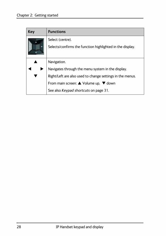
Select (centre).
Selects/confirms the function highlighted in the display.
Navigation.
Navigates through the menu system in the display.
Right/Left are also used to change settings in the menus.
From main screen: Volume up, down
See also Keypad shortcuts on page 31.
Key Functions
28 IP Handset keypad and display
Chapter 2: Getting started2
22
2
Get
ting
sta
rted
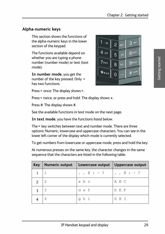
Alpha-numeric keys
This section shows the functions of the alpha-numeric keys in the lower section of the keypad.
The functions available depend on whether you are typing a phone number (number mode) or text (text mode).
In number mode, you get the number of the key pressed. Only has two functions.
Press once: The display shows .
Press twice, or press and hold: The display shows +.
Press #: The display shows #.
See the available functions in text mode on the next page.
In text mode, you have the functions listed below.
The key switches between text and number mode. There are three options: Numeric, lowercase and uppercase characters. You can see in the lower left corner of the display which mode is currently selected.
To get numbers from lowercase or uppercase mode, press and hold the key.
At numerous presses on the same key, the character changes in the same sequence that the characters are listed in the following table.
Key Numeric output Lowercase output Uppercase output
1 1 . , @ : - ? . , @ : - ?
2 2 a b c A B C
3 3 d e f D E F
4 4 g h i G H I
IP Handset keypad and display 29
Chapter 2: Getting started
5 5 j k l J K L
6 6 m n o M N O
7 7 p q r s P Q R S
8 8 t u v T U V
9 9 w x y z W X Y Z
0 0 [space] [space]
Switches between lowercase, uppercase and numbers
# Symbols. Displays a list with the following additional symbols:
. / : @ $ % ^ & * ( ) ~ ‘ - _ = + [ ] { } \ | ; ´ “ ! < > , ? # € <CR>
Key Numeric output Lowercase output Uppercase output
30 IP Handset keypad and display
Chapter 2: Getting started2
22
2
Get
ting
sta
rted
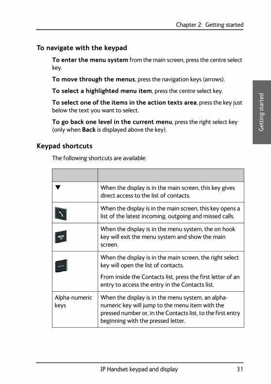
To navigate with the keypad
To enter the menu system from the main screen, press the centre select key.
To move through the menus, press the navigation keys (arrows).
To select a highlighted menu item, press the centre select key.
To select one of the items in the action texts area, press the key just below the text you want to select.
To go back one level in the current menu, press the right select key (only when Back is displayed above the key).
Keypad shortcuts
The following shortcuts are available:
When the display is in the main screen, this key gives direct access to the list of contacts.
When the display is in the main screen, this key opens a list of the latest incoming, outgoing and missed calls.
When the display is in the menu system, the on hook key will exit the menu system and show the main screen.
When the display is in the main screen, the right select key will open the list of contacts.
From inside the Contacts list, press the first letter of an entry to access the entry in the Contacts list.
Alpha-numeric keys
When the display is in the menu system, an alpha-numeric key will jump to the menu item with the pressed number or, in the Contacts list, to the first entry beginning with the pressed letter.
IP Handset keypad and display 31
Chapter 2: Getting started
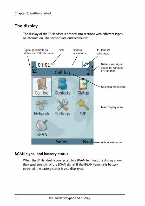
The display
The display of the IP Handset is divided into sections with different types of information. The sections are outlined below.
BGAN signal and battery status
When the IP Handset is connected to a BGAN terminal, the display shows the signal strength of the BGAN signal. If the BGAN terminal is battery powered, the battery status is also displayed.
Time IP Handset call status
Selected menu item
General Signal (and battery)
Action texts area
Main display area
Battery and signalstatus for wirelessIP Handset
status for BGAN terminal indications
32 IP Handset keypad and display

Chapter 2: Getting started2
22
2
Get
ting
sta
rted
Time
The display shows the time of day.
The format is selectable in the Settings > Date and time menu.
General indications
General indications are icons that show dynamic information such as missed calls, sounds off, keypad locked and microphone muted.
For explanations of the icons, see Icons in the display on page 34.
IP Handset call status
This field shows handset status such as whether or not the handset is ready for making calls, or whether there is an ongoing call.
For explanations of the icons, see Icons in the display on page 34.
Signal and battery status for wireless IP Handset
This field shows the signal strength for the wireless connection and battery status for the wireless handset.
Main display area
The main display area primarily displays the menus and messages to the user.
Action texts area
The action texts are used to indicate an action that takes place when the corresponding key is pressed. The corresponding key is the key directly below the text (left select, centre select or right select).
IP Handset keypad and display 33
Chapter 2: Getting started
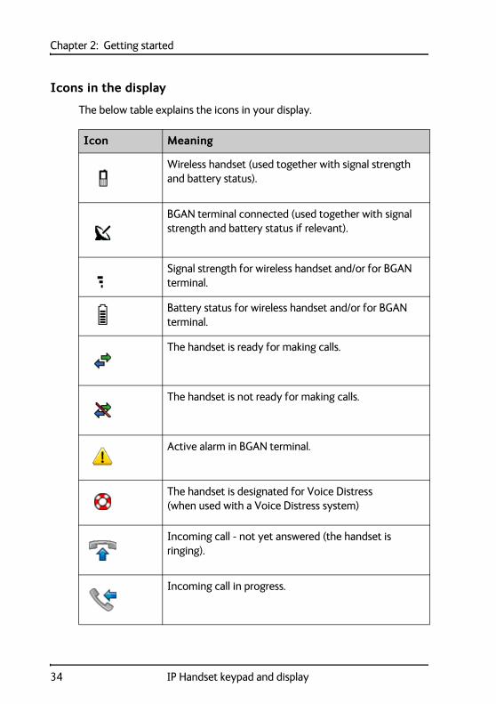
Icons in the display
The below table explains the icons in your display.
Icon Meaning
Wireless handset (used together with signal strength and battery status).
BGAN terminal connected (used together with signal strength and battery status if relevant).
Signal strength for wireless handset and/or for BGAN terminal.
Battery status for wireless handset and/or for BGAN terminal.
The handset is ready for making calls.
The handset is not ready for making calls.
Active alarm in BGAN terminal.
The handset is designated for Voice Distress (when used with a Voice Distress system)
Incoming call - not yet answered (the handset is ringing).
Incoming call in progress.
34 IP Handset keypad and display
Chapter 2: Getting started2
22
2
Get
ting
sta
rted
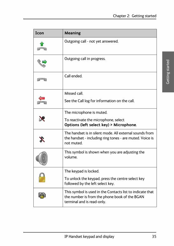
Outgoing call - not yet answered.
Outgoing call in progress.
Call ended.
Missed call.
See the Call log for information on the call.
The microphone is muted.
To reactivate the microphone, select Options (left select key) > Microphone.
The handset is in silent mode. All external sounds from the handset - including ring tones - are muted. Voice is not muted.
This symbol is shown when you are adjusting the volume.
The keypad is locked.
To unlock the keypad, press the centre select key followed by the left select key.
This symbol is used in the Contacts list to indicate that the number is from the phone book of the BGAN terminal and is read-only.
Icon Meaning
IP Handset keypad and display 35
Chapter 2: Getting started
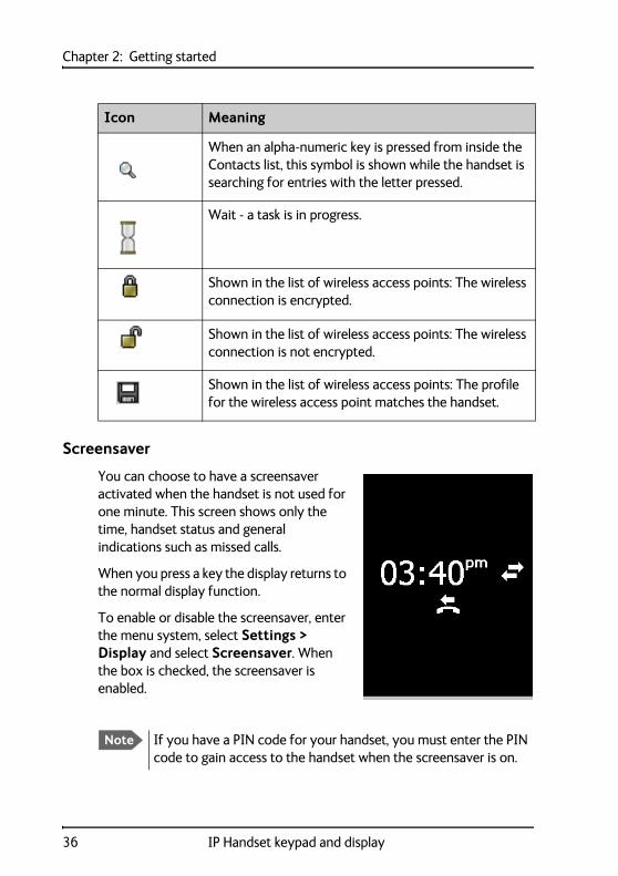
Screensaver
You can choose to have a screensaver activated when the handset is not used for one minute. This screen shows only the time, handset status and general indications such as missed calls.
When you press a key the display returns to the normal display function.
To enable or disable the screensaver, enter the menu system, select Settings > Display and select Screensaver. When the box is checked, the screensaver is enabled.
When an alpha-numeric key is pressed from inside the Contacts list, this symbol is shown while the handset is searching for entries with the letter pressed.
Wait - a task is in progress.
Shown in the list of wireless access points: The wireless connection is encrypted.
Shown in the list of wireless access points: The wireless connection is not encrypted.
Shown in the list of wireless access points: The profile for the wireless access point matches the handset.
Icon Meaning
Note If you have a PIN code for your handset, you must enter the PIN code to gain access to the handset when the screensaver is on.
36 IP Handset keypad and display
Chapter 333
33
Usi
ng th
e IP
Han
dset
Using the IP Handset 3
This chapter describes how to use the IP Handset. It also describes how to configure the handset and use the display menu system, including a short description of how to use the IP Handset with a BGAN terminal.
For information on how to connect and start up the handset, and how to navigate with the keypad, refer to the previous chapter, Getting started.
User interfaces
The main user interface for the handset is the display menu system. However, with a computer and a browser you can also use the built-in web server to access a subset of the handset settings. This way you can take advantage of a larger screen and still access a subset of the handset settings.
• The display menu system is described in IP Handset menus on page 56. For an overview of the keys and display, and explanation of keys and display symbols, see IP Handset keypad and display on page 26.
• The web server is described in Using the web server on page 91.
37

Chapter 3: Using the IP Handset
IP Handset functions
Handling calls
Handset ready
When the status field for the IP Handset shows ready , you can make or receive calls.
To make a call
To make a call, simply type the phone number and press or #.
Note If the handset is in the cradle while you make the call, the mode will automatically be hands-free (default function). For further information, see To set up the function of the cradle on page 71.
38 IP Handset functions
Chapter 3: Using the IP Handset 33
33
Usi
ng th
e IP
Han
dset
The display shows the progress as follows:
You can also call a number from your contacts or from a list of recent calls:
• Contacts: Press the right select key from the main screen and move to the contact you want to call. Then press the off hook key.
• Recent calls: To see the latest calls (incoming, outgoing and missed calls), press from the main screen. Press again to call the selected number.
Press off hook
Hang up
The call is answered
IP Handset functions 39
Chapter 3: Using the IP Handset
For information on how to make calls using a BGAN terminal, see Making a call using a BGAN terminal on page 46.
To receive a call
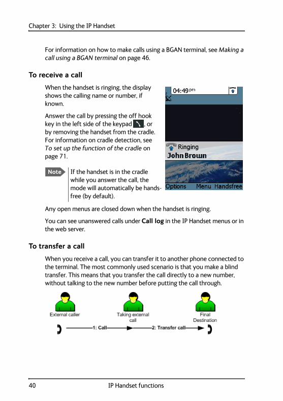
When the handset is ringing, the display shows the calling name or number, if known.
Answer the call by pressing the off hook key in the left side of the keypad , or by removing the handset from the cradle. For information on cradle detection, see To set up the function of the cradle on page 71.
Any open menus are closed down when the handset is ringing.
You can see unanswered calls under Call log in the IP Handset menus or in the web server.
To transfer a call
When you receive a call, you can transfer it to another phone connected to the terminal. The most commonly used scenario is that you make a blind transfer. This means that you transfer the call directly to a new number, without talking to the new number before putting the call through.
Note If the handset is in the cradle while you answer the call, the mode will automatically be hands-free (by default).
40 IP Handset functions
Chapter 3: Using the IP Handset 33
33
Usi
ng th
e IP
Han
dset
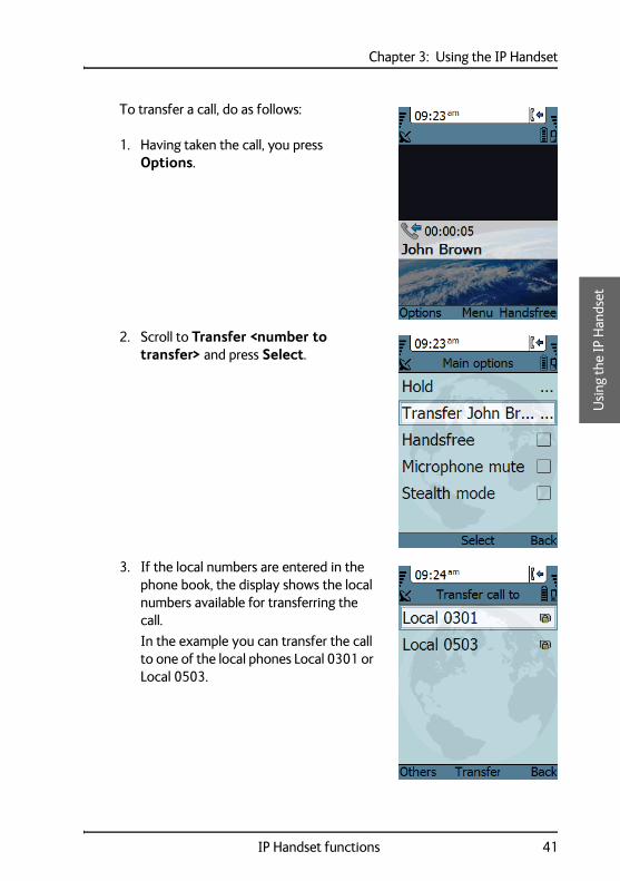
To transfer a call, do as follows:
1. Having taken the call, you press Options.
2. Scroll to Transfer <number to transfer> and press Select.
3. If the local numbers are entered in the phone book, the display shows the local numbers available for transferring the call.
In the example you can transfer the call to one of the local phones Local 0301 or Local 0503.
IP Handset functions 41
Chapter 3: Using the IP Handset
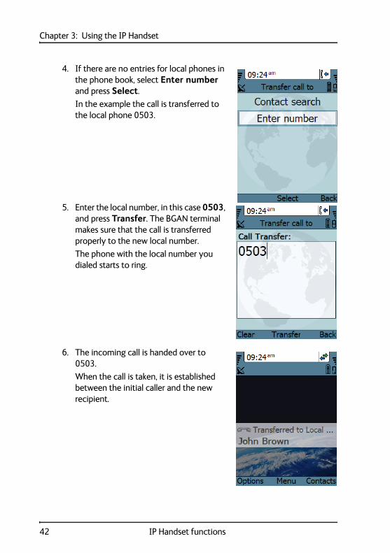
4. If there are no entries for local phones in the phone book, select Enter number and press Select.
In the example the call is transferred to the local phone 0503.
5. Enter the local number, in this case 0503, and press Transfer. The BGAN terminal makes sure that the call is transferred properly to the new local number.
The phone with the local number you dialed starts to ring.
6. The incoming call is handed over to 0503.
When the call is taken, it is established between the initial caller and the new recipient.
42 IP Handset functions
Chapter 3: Using the IP Handset 33
33
Usi
ng th
e IP
Han
dset
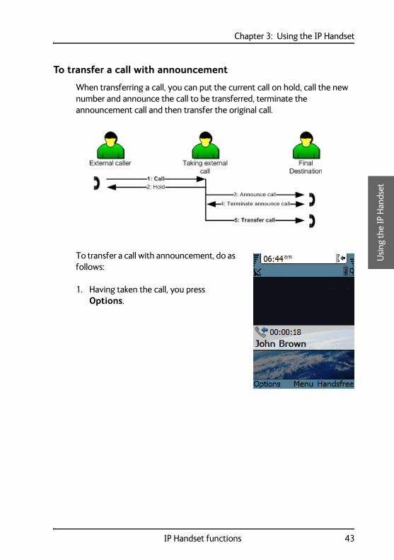
To transfer a call with announcement
When transferring a call, you can put the current call on hold, call the new number and announce the call to be transferred, terminate the announcement call and then transfer the original call.
To transfer a call with announcement, do as follows:
1. Having taken the call, you press Options.
IP Handset functions 43
Chapter 3: Using the IP Handset
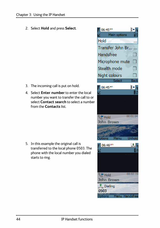
2. Select Hold and press Select.
3. The incoming call is put on hold.
4. Select Enter number to enter the local number you want to transfer the call to or select Contact search to select a number from the Contacts list.
5. In this example the original call is transferred to the local phone 0503. The phone with the local number you dialed starts to ring.
44 IP Handset functions

Chapter 3: Using the IP Handset 33
33
Usi
ng th
e IP
Han
dset
6. When 0503 picks up the call you can announce the original call that is on hold.
7. To be able to transfer the original call that is on hold, the announcement call to the local number must be terminated, either by you or the final recipient. This is to free the line for the original call.
Press the on-hook key to terminate the announcement call, in this example the call to 0503.
In case you need to talk to the original caller again, press Switch.
8. If you wish to talk to the original caller again before transferring the call, select Unhold.
Select Transfer to transfer the original caller.
Proceed as described in To transfer a call on page 40.
Note The BGAN system only supports one external call at a time.
IP Handset functions 45
Chapter 3: Using the IP Handset
To end or reject a call
Press the on hook key to end an ongoing call or to reject an incoming call.
When the handset is in hand-held mode, you can also end the call by placing the handset in the cradle.
Making a call using a BGAN terminal
When making a call with the IP Handset using a BGAN terminal you use the BGAN network and its functionality.
To make a call from a handset connected to a BGAN terminal
To make a call from a phone or handset connected to a BGAN terminal, dial
00 <country code> <phone number> followed by or #.
Example: To call Thrane & Thrane in Denmark (+45 39558800), dial 00 45 39558800 followed by or #.
To make a call to a handset connected to a BGAN terminal
To make a call to a handset connected to the BGAN terminal, dial
+870 <Mobile number>
Note The default call type is set up in the web interface of the BGAN terminal. However, you can select the call type for your call, using a prefix.
Dial 1 * before the number to make a Standard Voice call.
Dial 2 * before the number to make a 3.1 kHz Audio call.
Example: Dial 2 * 004539558800 to make a 3.1 kHz Audio call to Thrane & Thrane in Denmark.
Note By default all handsets connected to the terminal will ring on incoming calls.
46 IP Handset functions
Chapter 3: Using the IP Handset 33
33
Usi
ng th
e IP
Han
dset
• + is the prefix used in front of the country code for international calls. This is 00 when calling from most countries.
• Mobile number: The mobile number of the BGAN terminal you are calling.
Example: If you are calling from Denmark and the mobile number for 3.1 kHz Audio is 772112345 on your BGAN terminal, and you want to make a call to the BGAN terminal using 3.1 kHz Audio, dial 00 870 772112345.
To see the mobile numbers of your BGAN terminal, refer to the information included with your airtime subscription.
For more information on call types and the BGAN terminal, refer to the user manual for your BGAN terminal.
Using the IP Handset for Voice Distress
When used with a BGAN terminal, the IP Handset can be used to make Distress calls initiated by the SAILOR 3771 Alarm Panel. For instructions how to configure the IP Handset for Voice Distress see the Voice Distress (Non-SOLAS) User manual.
Making a secure call from the IP Handset
The IP Handset supports secure peer-to-peer voice calls. You can make secure calls to all IP phones complying with the ZRTP version used by the IP Handset, see Technical specifications on page 111. Standard X.509 certificate has been added for Stronger Authentication (SA) for closed user groups.
Note There are two Voice numbers, one for Standard Voice and one for 3.1 kHz Audio.
IP Handset functions 47
Chapter 3: Using the IP Handset
To configure the IP Handset for secure calling
You need your SIP account details to configure the IP Handset. The configuration is the same, whether you use the IP Handset with a BGAN terminal or a router.
To configure a router or a BGAN terminal do as follows:
Note SIP Service Provider details: In order to make a secure call you must have a SIP account at a SIP Service Provider. You must make sure
• that the Service Provider allows for the ZRTP protocol
• if calling from a BGAN terminal, the Service Provider allows for RTP streaming through the Service Provider’s server.
Unit Description
Router Please refer to the manufacturer’s documentation.
BGAN terminal The configuration of the IP connection of the BGAN terminal determines the speech quality of the IP Handset. The following two examples show a high-quality and a best-effort quality.
• Secure connection with guaranteed high speech quality: Start a Streaming data session at 64 kbps. The IP Handset is by default configured to G711 codec (64 kbit).
• Secure connection with best-effort speech quality: Start a Standard data session. In this case set the codec priority in the SIP profile of the IP Handset to G.729. For details see To edit a SIP profile on page 83.
48 IP Handset functions

Chapter 3: Using the IP Handset 33
33
Usi
ng th
e IP
Han
dset
To configure the IP Handset do as follows:
1. Make a SIP profile using the SIP account details SIP server, user name and password. For instructions see To add a new SIP profile on page 80.
2. Select SIP from the main menu, then select the new SIP profile you want to use for communication.
3. Select Connect. The handset registers itself, and you are ready to make a secure call.
Typically you make the call and then go into secure mode by selecting Go secure in the menu Main options. You can go into secure mode anytime during a call. When using the IP Handset in networks where all calls must be secure, you can set the handset to start a secure session automatically each time when a call is initiated and the peer IP Handset goes off-hook. For further details see To set call services (Noise cancellation and Automatic secure) on page 70.
To make a secure call
1. To make a secure call, type the phone number and press or #.
2. To go secure, the caller or the person called presses Main options, then Go secure to initiate a secure session. Then the display shows Going secure.
The encryption keys are negotiated, the peer is authenticated and the voice streaming is en- and decrypted.
The key negotiation may take up to 30 seconds. During this period, voice is muted.
IP Handset functions 49
Chapter 3: Using the IP Handset
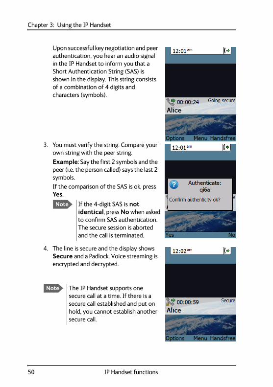
Upon successful key negotiation and peer authentication, you hear an audio signal in the IP Handset to inform you that a Short Authentication String (SAS) is shown in the display. This string consists of a combination of 4 digits and characters (symbols).
3. You must verify the string. Compare your own string with the peer string.
Example: Say the first 2 symbols and the peer (i.e. the person called) says the last 2 symbols.
If the comparison of the SAS is ok, press Yes.
4. The line is secure and the display shows Secure and a Padlock. Voice streaming is encrypted and decrypted.
Note If the 4-digit SAS is not identical, press No when asked to confirm SAS authentication. The secure session is aborted and the call is terminated.
Note The IP Handset supports one secure call at a time. If there is a secure call established and put on hold, you cannot establish another secure call.
50 IP Handset functions
Chapter 3: Using the IP Handset 33
33
Usi
ng th
e IP
Han
dset
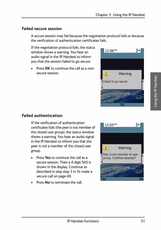
Failed secure session
A secure session may fail because the negotiation protocol fails or because the verification of authentication certificates fails.
If the negotiation protocol fails, the status window shows a warning. You hear an audio signal in the IP Handset to inform you that the session failed to go secure.
• Press OK to continue the call as a non-secure session.
Failed authentication
If the verification of authentication certificates fails (the peer is not member of the closed user group), the status window shows a warning. You hear an audio signal in the IP Handset to inform you that the peer is not a member of the closed user group.
• Press Yes to continue the call as a secure session. Then a 4-digit SAS is shown in the display. Continue as described in step step 3 in To make a secure call on page 49.
• Press No to terminate the call.
IP Handset functions 51
Chapter 3: Using the IP Handset
Quick settings
To control the volume in the earpiece
To adjust the voice volume during a call (with the display in the main screen), press or on the keypad.
To use hands-free operation
To enable hands-free operation during a call, use the right select key to select Handsfree. To go back to hand-held mode, press the right select key again.
In hands-free mode the sound is routed to a speaker, so that you can use the phone without holding it close to the ear. You can adjust the volume with or as described in the previous section.
Handset in cradle:
You can also make a hands-free call by leaving the handset in the cradle while making the call. Similarly you can answer a call using hands-free mode by leaving the handset in the cradle while answering the call.
In both cases, the default function is as follows:
• If you remove the handset from the cradle during the call, the mode will automatically change to hand-held.
• When the handset is out of the cradle in hand-held mode, the call will be terminated when you put the handset back in the cradle.
• When the handset is out of the cradle in hands-free mode, you can put it back in the cradle without terminating the call.
Note You can change this default function under Settings > Cradle, if you want the handset to be independent of the cradle. For further information, see To set up the function of the cradle on page 71.
52 IP Handset functions
Chapter 3: Using the IP Handset 33
33
Usi
ng th
e IP
Han
dset
To mute the microphone
You can mute the microphone of the IP Handset. To mute the microphone during a call, do as follows:
1. Select the left Options menu.
2. Select Microphone mute.
To lock the keypad
You can lock the keypad of the IP Handset. When the keypad is locked you can still answer incoming calls. To lock the keypad, do as follows:
1. Select the left Options menu.
2. Select Keypad lock.
To unlock the keypad, do as follows:
1. Press the centre select key.
2. Press the left select key.
To use night mode
The display has a night mode for operation in low light areas. In night mode, the colours are changed to make the display more suitable for night operation. The IP Handset can be set to automatically switch between day and night mode.
If the automatic switch between day and night mode is not selected, you can activate the night mode manually.
To activate night mode, do as follows:
1. Select the left Options menu.
2. Select Night mode.
IP Handset functions 53
Chapter 3: Using the IP Handset
To set the IP Handset to automatic switch between day and night mode see To set up the display on page 72.
To use stealth mode
Stealth mode is used when the IP Handset should not be noticed. In stealth mode you can turn off all lights in the display and/or sounds for external events. Note, however, that the keypad will still light up when you press a key.
To activate stealth mode, do as follows:
1. Select the left Options menu.
2. Select Stealth mode.
How to enter text in the IP Handset
When entering your contacts in the IP Handset you use the keypad to enter the names.
Press before the alpha-numeric key to switch between lower case, upper case and numbers.
There are 3 or 4 letters on each key. To obtain the next letter on the key, press the key again.
To move the cursor in the text, use the arrow keys.
To delete the letter just before the cursor, press the left select key Clear. Hold the key to delete all the text.
For a list of the key-functions in text-mode, see the table on page 29.
Note Stealth mode is only activated for the items you have selected in the menu Settings, Stealth. See To set up stealth mode on page 69.
54 IP Handset functions
Chapter 3: Using the IP Handset 33
33
Usi
ng th
e IP
Han
dset
Example
To type “He”, do as follows:
1. Press one or two times until the lower left corner of the display shows upper case letters.
2. Press the key 4 ghi two times to display the letter H.
3. Press again until the lower left corner of the display shows lower case letters.
4. Press the key 3 def two times to display the letter e.
Using a headset
You can connect a headset to the wireless IP Handset as follows:
Plug the headset jack into the jack connector on the side of the handset.
The microphone and speaker of the IP Handset are automatically disabled and the headset is used instead.
IP Handset functions 55

Chapter 3: Using the IP Handset
IP Handset menus
The menu system gives you access to the user parameters of the IP Handset. To access the menu system from the main screen, press the centre select key. Move around in the menus with the arrow keys and select with the select keys. Leave the menu system by pressing the on hook key.
Note The menus Wireless network under Network, Country under Network > Settings and Automatic shut down under Settings are only present in the Wireless IP Handset.
56 IP Handset menus
Chapter 3: Using the IP Handset 33
33
Usi
ng th
e IP
Han
dset
Call log
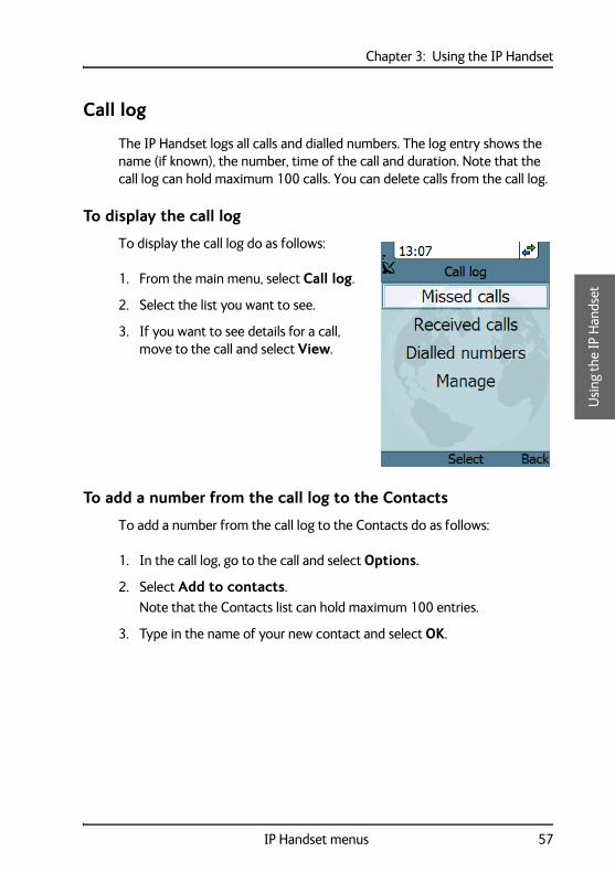
The IP Handset logs all calls and dialled numbers. The log entry shows the name (if known), the number, time of the call and duration. Note that the call log can hold maximum 100 calls. You can delete calls from the call log.
To display the call log
To display the call log do as follows:
1. From the main menu, select Call log.
2. Select the list you want to see.
3. If you want to see details for a call, move to the call and select View.
To add a number from the call log to the Contacts
To add a number from the call log to the Contacts do as follows:
1. In the call log, go to the call and select Options.
2. Select Add to contacts.
Note that the Contacts list can hold maximum 100 entries.
3. Type in the name of your new contact and select OK.
IP Handset menus 57
Chapter 3: Using the IP Handset
To delete a number from the call log
To delete a number from the call log do as follows:
1. In the call log, go to the call and select Options.
2. Select Delete.
3. Select Yes.
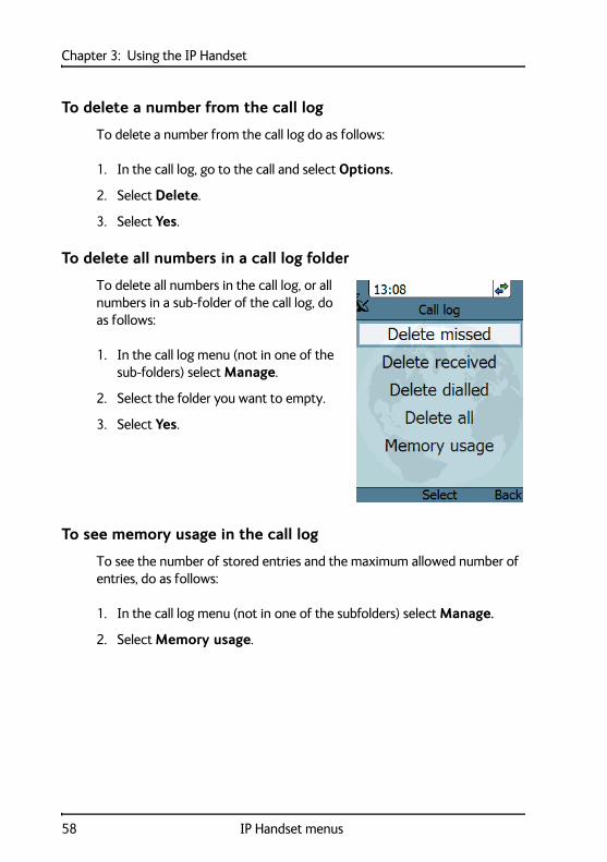
To delete all numbers in a call log folder
To delete all numbers in the call log, or all numbers in a sub-folder of the call log, do as follows:
1. In the call log menu (not in one of the sub-folders) select Manage.
2. Select the folder you want to empty.
3. Select Yes.
To see memory usage in the call log
To see the number of stored entries and the maximum allowed number of entries, do as follows:
1. In the call log menu (not in one of the subfolders) select Manage.
2. Select Memory usage.
58 IP Handset menus
Chapter 3: Using the IP Handset 33
33
Usi
ng th
e IP
Han
dset
Contacts
Use the contact list of the IP Handset to find a contact and make a call or manage your contacts. You have access to the contacts in the BGAN phone book.
To display your contacts
To display your contacts, do one of the following:
• From the main screen, press the right select key,
• from the main screen, press , or
• from the main menu, select Contacts.
If a contact is from the BGAN phone book it is marked with . This means you cannot edit or delete the entry.
To call a contact
To call a contact, do as follows:
1. In your Contacts list, scroll to the contact you want to call.
2. Press the off hook key.
To add a contact
To add a contact, do as follows:
1. In your Contacts list, press the left select key, Options.
2. Select Add.
Note that the Contacts list can hold maximum 100 entries.
3. Type in the name of your contact and select OK.
The name can be maximum 32 characters.
For information on how to enter text, see How to enter text in the IP Handset on page 54.
4. Scroll to Number and select Edit.
5. Type in the number of your contact and select OK.
IP Handset menus 59
Chapter 3: Using the IP Handset
The number can be maximum 32 characters.
To edit a contact
To edit a contact, do as follows:
1. In your Contacts list, scroll to the contact you want to edit.
2. Press the left select key, Options.
3. Select View/Edit.
4. Select Edit.
5. Change the name of your contact and select OK.
For information on how to enter text, see How to enter text in the IP Handset on page 54.
6. Scroll to Number and select Edit.
7. Change the number of your contact and select OK.
To delete a contact
To delete a contact, do as follows:
1. In your Contacts list, scroll to the contact you want to delete.
2. Press the left select key, Options.
3. Select Delete.
4. Press the left select key, Yes.
The contact is now deleted from your Contacts list.
60 IP Handset menus
Chapter 3: Using the IP Handset 33
33
Usi
ng th
e IP
Han
dset
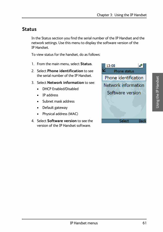
Status
In the Status section you find the serial number of the IP Handset and the network settings. Use this menu to display the software version of the IP Handset.
To view status for the handset, do as follows:
1. From the main menu, select Status.
2. Select Phone identification to see the serial number of the IP Handset.
3. Select Network information to see:
• DHCP Enabled/Disabled
• IP address
• Subnet mask address
• Default gateway
• Physical address (MAC)
4. Select Software version to see the version of the IP Handset software.
IP Handset menus 61
Chapter 3: Using the IP Handset
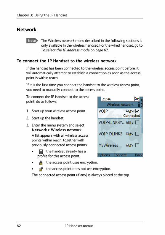
Network
To connect the IP Handset to the wireless network
If the handset has been connected to the wireless access point before, it will automatically attempt to establish a connection as soon as the access point is within reach.
If it is the first time you connect the handset to the wireless access point, you need to manually connect to the access point.
To connect the IP Handset to the access point, do as follows:
1. Start up your wireless access point.
2. Start up the handset.
3. Enter the menu system and select Network > Wireless network.
A list appears with all wireless access points within reach, together with previously connected access points.
• : the handset already has a profile for this access point.
• : the access point uses encryption.
• : the access point does not use encryption.
The connected access point (if any) is always placed at the top.
Note The Wireless network menu described in the following sections is only available in the wireless handset. For the wired handset, go to To select the IP address mode on page 67.
62 IP Handset menus

Chapter 3: Using the IP Handset 33
33
Usi
ng th
e IP
Han
dset
4. Select Connect at the network you want to connect to.
If your access point does not use encryption, the handset will automatically connect and create a new profile for the access point.
5. If your access point uses encryption and it is the first time you connect, you are prompted for security settings, select OK to enter the Profiles menu. Set the security settings as described in To connect the IP Handset to the wireless network on page 62.
When the profile matches the access point, and you have selected Connect, the IP Handset attempts to establish a connection. If the access point is connected to a BGAN terminal, see Using a BGAN terminal on page 20 for information on how to connect to the BGAN network.
When the handset is ready for use, you see the handset ready symbol in the top right corner of the display.
Normally a new profile is automatically created when you connect to an access point.
IP Handset menus 63
Chapter 3: Using the IP Handset
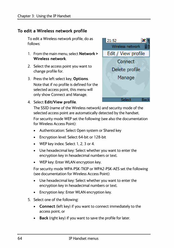
To edit a Wireless network profile
To edit a Wireless network profile, do as follows:
1. From the main menu, select Network > Wireless network.
2. Select the access point you want to change profile for.
3. Press the left select key, Options.
Note that if no profile is defined for the selected access point, this menu will only show Connect and Manage.
4. Select Edit/View profile.
The SSID (name of the Wireless network) and security mode of the selected access point are automatically detected by the handset.
For security mode WEP set the following (see also the documentation for Wireless Access Point):
• Authentication: Select Open system or Shared key
• Encryption level: Select 64-bit or 128-bit
• WEP key index: Select 1, 2, 3 or 4.
• Use hexadecimal key: Select whether you want to enter the encryption key in hexadecimal numbers or text.
• WEP key: Enter WLAN encryption key.
For security mode WPA-PSK-TKIP or WPA2-PSK-AES set the following (see documentation for Wireless Access Point):
• Use hexadecimal key: Select whether you want to enter the encryption key in hexadecimal numbers or text.
• Encryption key: Enter WLAN encryption key.
5. Select one of the following:
• Connect (left key) if you want to connect immediately to the access point, or
• Back (right key) if you want to save the profile for later.
64 IP Handset menus

Chapter 3: Using the IP Handset 33
33
Usi
ng th
e IP
Han
dset
To delete a Wireless network profile
To delete a Wireless network profile, do as follows:
1. In the Wireless network list, go to the access point for which you want to delete the profile.
2. Select Options (left select).
3. Select Delete profile.
4. Select Yes (left select).
The profile for the selected access point is now deleted. If the access point uses encryption, your handset will not be able to connect to the access point unless the security settings are entered again.
To delete all Wireless network profiles
To delete all Wireless network profiles, do as follows:
1. From the Wireless network list, select Options (left select).
2. Select Manage.
3. Select Delete all profiles.
4. Select Yes (left select) to confirm.
Important When you delete all profiles you will not be able to connect to any access point using encryption, unless you enter the security settings again!
IP Handset menus 65
Chapter 3: Using the IP Handset
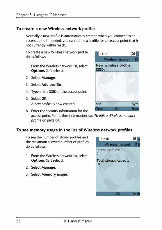
To create a new Wireless network profile
Normally a new profile is automatically created when you connect to an access point. If needed, you can define a profile for an access point that is not currently within reach.
To create a new Wireless network profile, do as follows:
1. From the Wireless network list, select Options (left select).
2. Select Manage.
3. Select Add profile.
4. Type in the SSID of the access point.
5. Select OK.
A new profile is now created
6. Enter the security information for the access point. For further information, see To edit a Wireless network profile on page 64.
To see memory usage in the list of Wireless network profiles
To see the number of stored profiles and the maximum allowed number of profiles, do as follows:
1. From the Wireless network list, select Options (left select).
2. Select Manage.
3. Select Memory usage.
66 IP Handset menus
Chapter 3: Using the IP Handset 33
33
Usi
ng th
e IP
Han
dset
To set the country for Wireless network use
To make sure you have the right settings for the country your IP Handset is currently located in, you have to enter the country in the handset.
To enter the country, do as follows:
1. Select Network > Settings > Country.
2. Scroll to the country your handset is located in and select it.
If the country is not in the list, select Other.
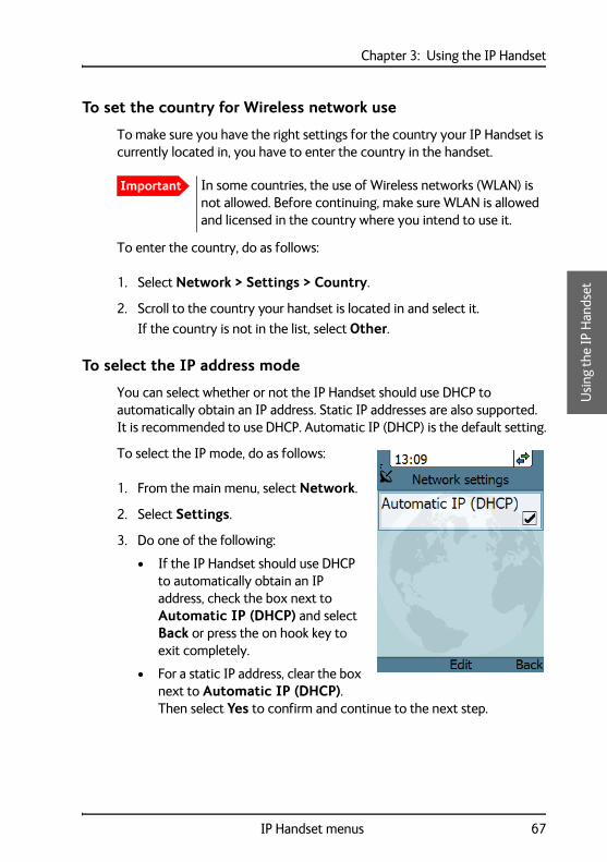
To select the IP address mode
You can select whether or not the IP Handset should use DHCP to automatically obtain an IP address. Static IP addresses are also supported. It is recommended to use DHCP. Automatic IP (DHCP) is the default setting.
To select the IP mode, do as follows:
1. From the main menu, select Network.
2. Select Settings.
3. Do one of the following:
• If the IP Handset should use DHCP to automatically obtain an IP address, check the box next to Automatic IP (DHCP) and select Back or press the on hook key to exit completely.
• For a static IP address, clear the box next to Automatic IP (DHCP). Then select Yes to confirm and continue to the next step.
Important In some countries, the use of Wireless networks (WLAN) is not allowed. Before continuing, make sure WLAN is allowed and licensed in the country where you intend to use it.
IP Handset menus 67
Chapter 3: Using the IP Handset
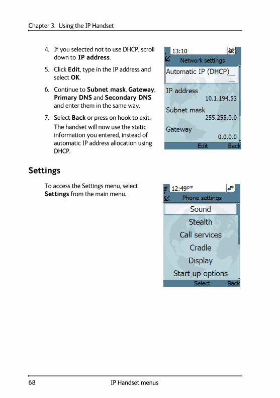
4. If you selected not to use DHCP, scroll down to IP address.
5. Click Edit, type in the IP address and select OK.
6. Continue to Subnet mask, Gateway, Primary DNS and Secondary DNS and enter them in the same way.
7. Select Back or press on hook to exit.
The handset will now use the static information you entered, instead of automatic IP address allocation using DHCP.
Settings
To access the Settings menu, select Settings from the main menu.
68 IP Handset menus

Chapter 3: Using the IP Handset 33
33
Usi
ng th
e IP
Han
dset
To adjust the sound
You can adjust the ringing tone, the tone volume and the keypad click.
To adjust the sounds of the handset, do as follows:
1. From the Settings menu, select Sound.
2. Use the arrow keys to move to the sound you want to adjust.
3. For Keypad click, select Edit to change the setting.
4. For the other settings, use the keys and to change the setting, or select Edit, select the setting you want and select OK.
To set up stealth mode
Stealth mode is used when the IP Handset should not be noticed. In stealth mode you can turn off all lights in the display and/or sounds for external events. Note, however, that the keypad will still light up when you press a key.
To configure and go into stealth mode, do as follows:
1. From the Settings menu, select Stealth.
2. Move to Suppress audio and/or Suppress backlight and select Edit to change the setting.
Note These settings are only activated when Use stealth is checked.
IP Handset menus 69
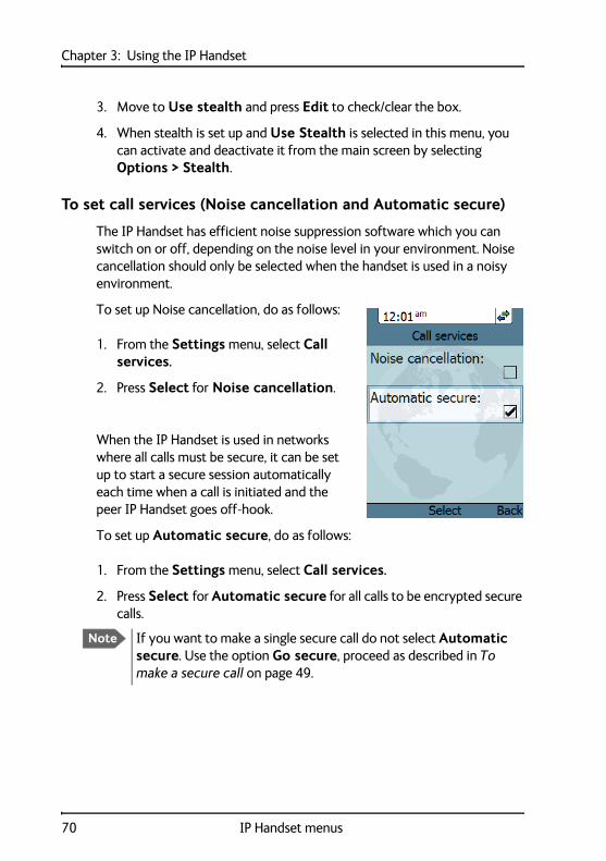
Chapter 3: Using the IP Handset
3. Move to Use stealth and press Edit to check/clear the box.
4. When stealth is set up and Use Stealth is selected in this menu, you can activate and deactivate it from the main screen by selecting Options > Stealth.
To set call services (Noise cancellation and Automatic secure)
The IP Handset has efficient noise suppression software which you can switch on or off, depending on the noise level in your environment. Noise cancellation should only be selected when the handset is used in a noisy environment.
To set up Noise cancellation, do as follows:
1. From the Settings menu, select Call services.
2. Press Select for Noise cancellation.
When the IP Handset is used in networks where all calls must be secure, it can be set up to start a secure session automatically each time when a call is initiated and the peer IP Handset goes off-hook.
To set up Automatic secure, do as follows:
1. From the Settings menu, select Call services.
2. Press Select for Automatic secure for all calls to be encrypted secure calls.
Note If you want to make a single secure call do not select Automatic secure. Use the option Go secure, proceed as described in To make a secure call on page 49.
70 IP Handset menus
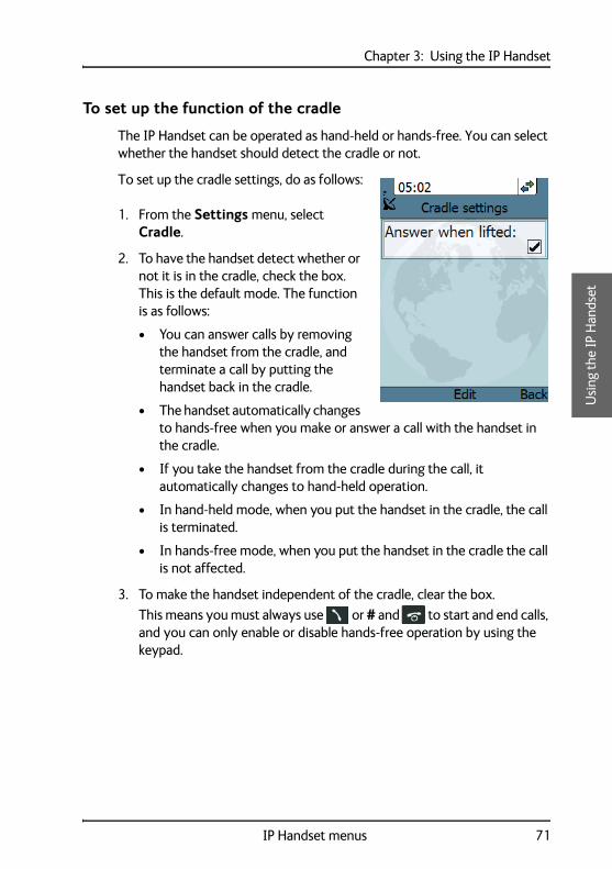
Chapter 3: Using the IP Handset 33
33
Usi
ng th
e IP
Han
dset
To set up the function of the cradle
The IP Handset can be operated as hand-held or hands-free. You can select whether the handset should detect the cradle or not.
To set up the cradle settings, do as follows:
1. From the Settings menu, select Cradle.
2. To have the handset detect whether or not it is in the cradle, check the box. This is the default mode. The function is as follows:
• You can answer calls by removing the handset from the cradle, and terminate a call by putting the handset back in the cradle.
• The handset automatically changes to hands-free when you make or answer a call with the handset in the cradle.
• If you take the handset from the cradle during the call, it automatically changes to hand-held operation.
• In hand-held mode, when you put the handset in the cradle, the call is terminated.
• In hands-free mode, when you put the handset in the cradle the call is not affected.
3. To make the handset independent of the cradle, clear the box.
This means you must always use or # and to start and end calls, and you can only enable or disable hands-free operation by using the keypad.
IP Handset menus 71
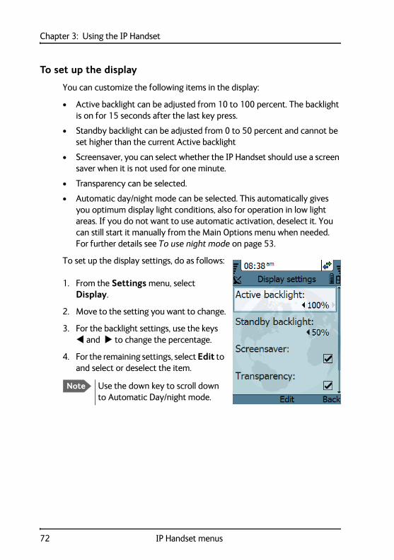
Chapter 3: Using the IP Handset
To set up the display
You can customize the following items in the display:
• Active backlight can be adjusted from 10 to 100 percent. The backlight is on for 15 seconds after the last key press.
• Standby backlight can be adjusted from 0 to 50 percent and cannot be set higher than the current Active backlight
• Screensaver, you can select whether the IP Handset should use a screen saver when it is not used for one minute.
• Transparency can be selected.
• Automatic day/night mode can be selected. This automatically gives you optimum display light conditions, also for operation in low light areas. If you do not want to use automatic activation, deselect it. You can still start it manually from the Main Options menu when needed. For further details see To use night mode on page 53.
To set up the display settings, do as follows:
1. From the Settings menu, select Display.
2. Move to the setting you want to change.
3. For the backlight settings, use the keys and to change the percentage.
4. For the remaining settings, select Edit to and select or deselect the item.
Note Use the down key to scroll down to Automatic Day/night mode.
72 IP Handset menus

Chapter 3: Using the IP Handset 33
33
Usi
ng th
e IP
Han
dset
To select the startup options
You can select whether or not you want to clear the log and the Contacts in your handset every time you start up the handset. You can also select whether or not you want handsets to be automatically set up when they are connected to a BGAN terminal.
To select the startup options, do as follows:
1. From the Settings menu, select startup options.
2. If you want to clear the logs and the Contacts at every startup, select Clear logs/Contacts. To leave the menu, select Back.
3. If you want the IP Handset to be set up automatically when it connects, select Auto BGAN SIP.
With this option selected, from next startup, the IP Handset will automatically be set up with the next available user name (local number) and password when connected to a BGAN terminal.
To leave the menu, select Back.
To disable or set automatic shut down (wireless handset only)
Per default the wireless IP Handset is set to shut down automatically if it does not receive a signal from a wireless access point for a certain period of time and is outside the cradle.
To disable or set automatic shut down, do as follows:
1. From the Settings menu, set or remove the check mark for Automatic shut down.
2. Use the keys and , or press Edit to select the wanted time interval before automatic power off. You have the following choices:
• Disabled
• 2, 5, 15, 30 or 60 minutes (default value: 30 minutes)
3. Select the time span.
4. Press Back to return to normal operation.
IP Handset menus 73
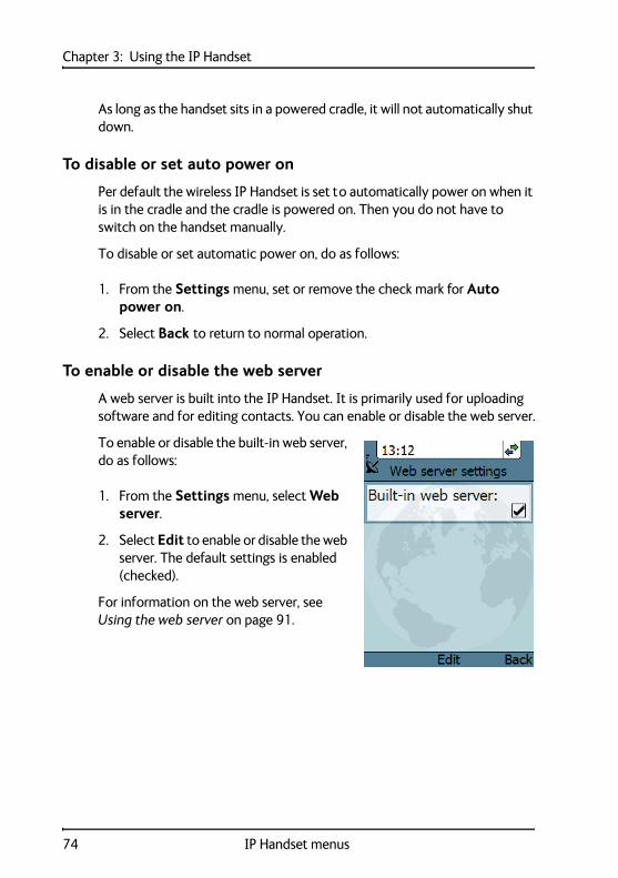
Chapter 3: Using the IP Handset
As long as the handset sits in a powered cradle, it will not automatically shut down.
To disable or set auto power on
Per default the wireless IP Handset is set to automatically power on when it is in the cradle and the cradle is powered on. Then you do not have to switch on the handset manually.
To disable or set automatic power on, do as follows:
1. From the Settings menu, set or remove the check mark for Auto power on.
2. Select Back to return to normal operation.
To enable or disable the web server
A web server is built into the IP Handset. It is primarily used for uploading software and for editing contacts. You can enable or disable the web server.
To enable or disable the built-in web server, do as follows:
1. From the Settings menu, select Web server.
2. Select Edit to enable or disable the web server. The default settings is enabled (checked).
For information on the web server, see Using the web server on page 91.
74 IP Handset menus
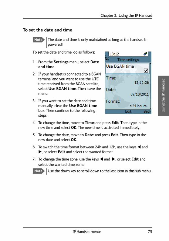
Chapter 3: Using the IP Handset 33
33
Usi
ng th
e IP
Han
dset
To set the date and time
To set the date and time, do as follows:
1. From the Settings menu, select Date and time.
2. If your handset is connected to a BGAN terminal and you want to use the UTC time received from the BGAN satellite, select Use BGAN time. Then leave the menu.
3. If you want to set the date and time manually, clear the Use BGAN time box. Then continue to the following steps.
4. To change the time, move to Time: and press Edit. Then type in the new time and select OK. The new time is activated immediately.
5. To change the date, move to Date: and press Edit. Then type in the new date and select OK.
6. To switch the time format between 24h and 12h, use the keys and , or select Edit and select the wanted format.
7. To change the time zone, use the keys and , or select Edit and select the wanted time zone.
Note The date and time is only maintained as long as the handset is powered!
Note Use the down key to scroll down to the last item in this sub menu.
IP Handset menus 75

Chapter 3: Using the IP Handset
To use a PIN code for the handset
If a PIN code is defined for the handset, it must be entered at startup and when the screensaver is active.
Note that you do not have to enter the PIN to:
• make emergency calls. You can type the emergency number in the PIN code screen.
• answer the phone when it is ringing.
For information on how to set up the PIN code for the handset, see the next section.
To set up the PIN code for the handset
To set up the PIN code for the handset, do as follows:
1. From the Settings menu, select PIN code.
Note There may be 2 PIN codes for the system:
• one for the BGAN terminal (SIM PIN, described in Establishing a connection on page 20) and
• one for the IP Handset (described in this section)
Important If you have entered a wrong PIN code 5 times, the handset is locked! Contact your distributor for an unblocking code.
76 IP Handset menus
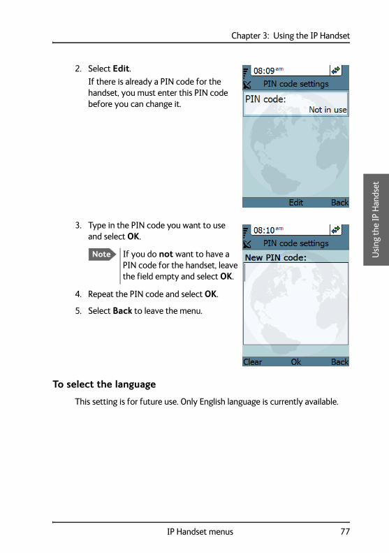
Chapter 3: Using the IP Handset 33
33
Usi
ng th
e IP
Han
dset
2. Select Edit.
If there is already a PIN code for the handset, you must enter this PIN code before you can change it.
3. Type in the PIN code you want to use and select OK.
4. Repeat the PIN code and select OK.
5. Select Back to leave the menu.
To select the language
This setting is for future use. Only English language is currently available.
Note If you do not want to have a PIN code for the handset, leave the field empty and select OK.
IP Handset menus 77

Chapter 3: Using the IP Handset
To apply factory default settings
You can reset the IP Handset to factory default settings.
To return to factory default for all settings, do as follows:
1. From the Settings menu, select Factory default.
2. Select Yes.
All settings and status information are now changed to factory default settings. Note that in some cases this operation may take up to 30 seconds.
Important All settings and status information are lost when you accept this setting!
78 IP Handset menus
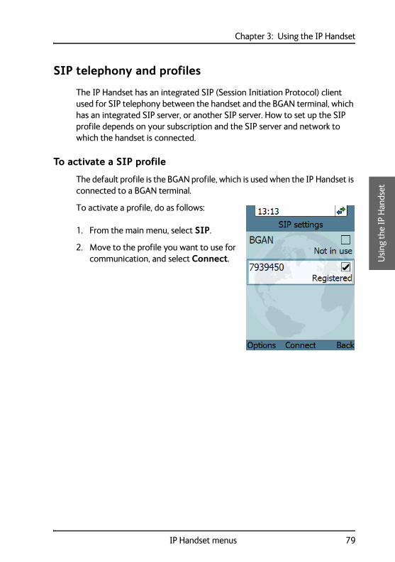
Chapter 3: Using the IP Handset 33
33
Usi
ng th
e IP
Han
dset
SIP telephony and profiles
The IP Handset has an integrated SIP (Session Initiation Protocol) client used for SIP telephony between the handset and the BGAN terminal, which has an integrated SIP server, or another SIP server. How to set up the SIP profile depends on your subscription and the SIP server and network to which the handset is connected.
To activate a SIP profile
The default profile is the BGAN profile, which is used when the IP Handset is connected to a BGAN terminal.
To activate a profile, do as follows:
1. From the main menu, select SIP.
2. Move to the profile you want to use for communication, and select Connect.
IP Handset menus 79
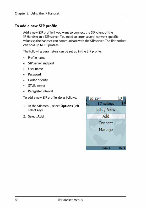
Chapter 3: Using the IP Handset
To add a new SIP profile
Add a new SIP profile if you want to connect the SIP client of the IP Handset to a SIP server. You need to enter several network specific values so the handset can communicate with the SIP server. The IP Handset can hold up to 10 profiles.
The following parameters can be set up in the SIP profile:
• Profile name
• SIP server and port
• User name
• Password
• Codec priority
• STUN server
• Reregister interval
To add a new SIP profile, do as follows:
1. In the SIP menu, select Options (left select key).
2. Select Add.
80 IP Handset menus

Chapter 3: Using the IP Handset 33
33
Usi
ng th
e IP
Han
dset
3. Type in the name to use for the new profile and select OK.
Example: The profile name is New Profile.
4. Move to SIP server and select Edit.
5. At Server name / IP:, select Edit again.
6. Type in the server name (URL) or IP address and select OK.
Example: Server name is voip.serv.
7. Type in the port number for the SIP server and select OK.
Example: Port number is 5060 (default setting),
8. Select Back to continue the setup of the remaining parameters.
IP Handset menus 81

Chapter 3: Using the IP Handset
9. Move to the setting you want to change and select Edit. Type in the information and enter with OK.
• User name: When connecting to a BGAN terminal, the user name should be the same as the local number for the handset.
• Password: When connecting to a BGAN terminal, the password must match the IP Handset password entered in the terminal.
• Codec priority: Select the codec type that should have the highest priority. You may select G711 or G729.
• STUN server: If your SIP telephony installation requires a STUN server name, you can enter it here. Refer to the documentation of the SIP server.
• Reregister every: This settings sets the time interval in which the IP Handset registers with the SIP server it is connected to. If the SIP server is the BGAN terminal, you don’t need to change this setting. The interval is set to 120 seconds (default). The maximum value is 86400 seconds (24 hours). If the connection to an external SIP provider is made through a NAT router, this setting may be needed to keep the connection through NAT to the SIP server open. This setting should in this case typically be set to 20 seconds.
10. When you have made the changes, select Back.
11. If you want to connect immediately with the new SIP profile, select Connect. If not, select Back to leave the menu.
Note Use the down key to scroll down to the last items in this sub menu.
Note If the IP Handset registers with the SIP server over a satellite connection or other telecommunications network you may set this time interval to a larger value to avoid unintended use of bandwidth.
82 IP Handset menus
Chapter 3: Using the IP Handset 33
33
Usi
ng th
e IP
Han
dset
To edit a SIP profile
To edit a SIP profile, do as follows:
1. In the list of profiles, go to the profile you want to change and select Options > Edit/View.
2. Edit the settings as described in the previous section.
To delete a SIP profile
To delete a SIP profile, do as follows:
1. In the SIP menu, move to the profile you want to delete and select Options.
2. Select Delete.
3. Select Yes.
IP Handset menus 83
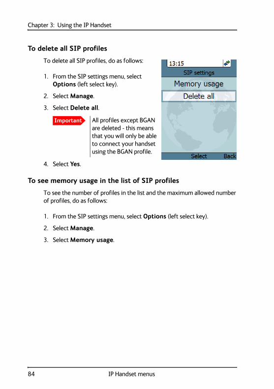
Chapter 3: Using the IP Handset
To delete all SIP profiles
To delete all SIP profiles, do as follows:
1. From the SIP settings menu, select Options (left select key).
2. Select Manage.
3. Select Delete all.
4. Select Yes.
To see memory usage in the list of SIP profiles
To see the number of profiles in the list and the maximum allowed number of profiles, do as follows:
1. From the SIP settings menu, select Options (left select key).
2. Select Manage.
3. Select Memory usage.
Important All profiles except BGAN are deleted - this means that you will only be able to connect your handset using the BGAN profile.
84 IP Handset menus
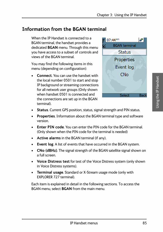
Chapter 3: Using the IP Handset 33
33
Usi
ng th
e IP
Han
dset
Information from the BGAN terminal
When the IP Handset is connected to a BGAN terminal, the handset provides a dedicated BGAN menu. Through this menu you have access to a subset of controls and views of the BGAN terminal.
You may find the following items in this menu (depending on configuration):
• Connect. You can use the handset with the local number 0501 to start and stop IP background or streaming connections for all network user groups (Only shown when handset 0501 is connected and the connections are set up in the BGAN terminal).
• Status. Current GPS position, status, signal strength and PIN status.
• Properties. Information about the BGAN terminal type and software version.
• Enter PIN code. You can enter the PIN code for the BGAN terminal. (Only shown when the PIN code for the terminal is needed)
• Active alarms in the BGAN terminal (if any).
• Event log. A list of events that have occurred in the BGAN system.
• CNo (dBHz). The signal strength of the BGAN satellite signal shown on a full screen.
• Voice Distress test for test of the Voice Distress system (only shown in Voice Distress systems).
• Terminal usage. Standard or X-Stream usage mode (only with EXPLORER 727 terminal).
Each item is explained in detail in the following sections. To access the BGAN menu, select BGAN from the main menu.
IP Handset menus 85
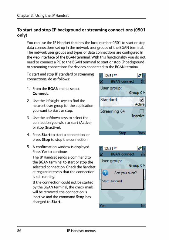
Chapter 3: Using the IP Handset
To start and stop IP background or streaming connections (0501 only)
You can use the IP Handset that has the local number 0501 to start or stop data connections set up in the network user groups of the BGAN terminal. The network user groups and types of data connections are configured in the web interface of the BGAN terminal. With this functionality you do not need to connect a PC to the BGAN terminal to start or stop IP background or streaming connections for devices connected to the BGAN terminal.
To start and stop IP standard or streaming connections, do as follows:
1. From the BGAN menu, select Connect.
2. Use the left/right keys to find the network user group for the application you want to start or stop.
3. Use the up/down keys to select the connection you wish to start (Active) or stop (Inactive).
4. Press Start to start a connection, or press Stop to stop the connection.
5. A confirmation window is displayed. Press Yes to continue.
The IP Handset sends a command to the BGAN terminal to start or stop the selected connection. Check the handset at regular intervals that the connection is still running.
If the connection could not be started by the BGAN terminal, the check mark will be removed, the connection is inactive and the command Stop has changed to Start.
86 IP Handset menus
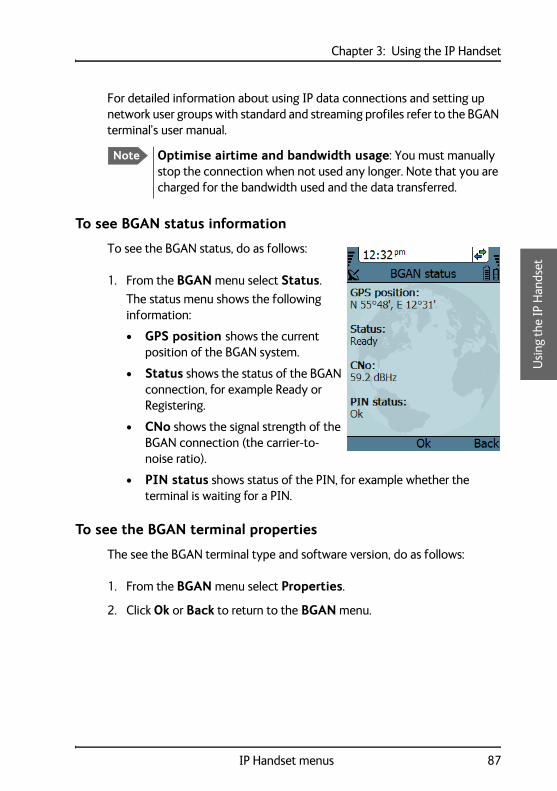
Chapter 3: Using the IP Handset 33
33
Usi
ng th
e IP
Han
dset
For detailed information about using IP data connections and setting up network user groups with standard and streaming profiles refer to the BGAN terminal’s user manual.
To see BGAN status information
To see the BGAN status, do as follows:
1. From the BGAN menu select Status.
The status menu shows the following information:
• GPS position shows the current position of the BGAN system.
• Status shows the status of the BGAN connection, for example Ready or Registering.
• CNo shows the signal strength of the BGAN connection (the carrier-to-noise ratio).
• PIN status shows status of the PIN, for example whether the terminal is waiting for a PIN.
To see the BGAN terminal properties
The see the BGAN terminal type and software version, do as follows:
1. From the BGAN menu select Properties.
2. Click Ok or Back to return to the BGAN menu.
Note Optimise airtime and bandwidth usage: You must manually stop the connection when not used any longer. Note that you are charged for the bandwidth used and the data transferred.
IP Handset menus 87
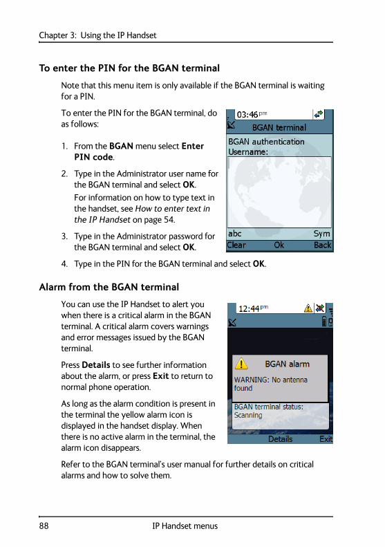
Chapter 3: Using the IP Handset
To enter the PIN for the BGAN terminal
Note that this menu item is only available if the BGAN terminal is waiting for a PIN.
To enter the PIN for the BGAN terminal, do as follows:
1. From the BGAN menu select Enter PIN code.
2. Type in the Administrator user name for the BGAN terminal and select OK.
For information on how to type text in the handset, see How to enter text in the IP Handset on page 54.
3. Type in the Administrator password for the BGAN terminal and select OK.
4. Type in the PIN for the BGAN terminal and select OK.
Alarm from the BGAN terminal
You can use the IP Handset to alert you when there is a critical alarm in the BGAN terminal. A critical alarm covers warnings and error messages issued by the BGAN terminal.
Press Details to see further information about the alarm, or press Exit to return to normal phone operation.
As long as the alarm condition is present in the terminal the yellow alarm icon is displayed in the handset display. When there is no active alarm in the terminal, the alarm icon disappears.
Refer to the BGAN terminal’s user manual for further details on critical alarms and how to solve them.
88 IP Handset menus
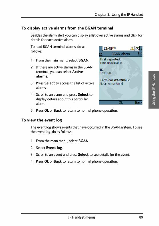
Chapter 3: Using the IP Handset 33
33
Usi
ng th
e IP
Han
dset
To display active alarms from the BGAN terminal
Besides the alarm alert you can display a list over active alarms and click for details for each active alarm.
To read BGAN terminal alarms, do as follows:
1. From the main menu, select BGAN.
2. If there are active alarms in the BGAN terminal, you can select Active alarms.
3. Press Select to access the list of active alarms.
4. Scroll to an alarm and press Select to display details about this particular alarm.
5. Press Ok or Back to return to normal phone operation.
To view the event log
The event log shows events that have occurred in the BGAN system. To see the event log, do as follows:
1. From the main menu, select BGAN.
2. Select Event log.
3. Scroll to an event and press Select to see details for the event.
4. Press Ok or Back to return to normal phone operation.
IP Handset menus 89
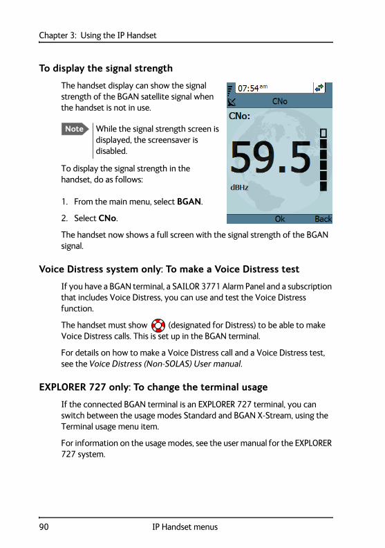
Chapter 3: Using the IP Handset
To display the signal strength
The handset display can show the signal strength of the BGAN satellite signal when the handset is not in use.
To display the signal strength in the handset, do as follows:
1. From the main menu, select BGAN.
2. Select CNo.
The handset now shows a full screen with the signal strength of the BGAN signal.
Voice Distress system only: To make a Voice Distress test
If you have a BGAN terminal, a SAILOR 3771 Alarm Panel and a subscription that includes Voice Distress, you can use and test the Voice Distress function.
The handset must show (designated for Distress) to be able to make Voice Distress calls. This is set up in the BGAN terminal.
For details on how to make a Voice Distress call and a Voice Distress test, see the Voice Distress (Non-SOLAS) User manual.
EXPLORER 727 only: To change the terminal usage
If the connected BGAN terminal is an EXPLORER 727 terminal, you can switch between the usage modes Standard and BGAN X-Stream, using the Terminal usage menu item.
For information on the usage modes, see the user manual for the EXPLORER 727 system.
Note While the signal strength screen is displayed, the screensaver is disabled.
90 IP Handset menus
Chapter 44
44
4
Usi
ng th
e w
eb s
erve
r
Using the web server 4
This chapter describes how to use the web server in your IP Handset system.
Introduction to the web server
The web server is built into the IP Handset and is primarily used for uploading software and for editing contacts in the IP Handset.
You can access the web server from a computer connected to the BGAN terminal you are using for the handset. Use a standard Internet browser.
91

Chapter 4: Using the web server
Browser settings
If you are connecting your computer using a LAN or WLAN interface, the Proxy server settings in your browser must be disabled before accessing the web interface. Most browsers support disabling of the Proxy server settings for one specific IP address, so you can disable Proxy server settings for the web interface only, if you wish. Consult your browser help for information.
To disable the use of a Proxy server completely, do as follows:
1. In Microsoft Internet Explorer, select Tools > Internet Options > Connections > LAN Settings.
2. Clear the box labeled Use a proxy server for your LAN.
3. Click OK.
Note The following description is for Microsoft Internet Explorer. If you are using a different browser, the procedure may be different.
92 Introduction to the web server
Chapter 4: Using the web server 44
44
Usi
ng th
e w
eb s
erve
r
When the proxy server settings are disabled, close and restart your browser. You may need to change this setting back on return to your Internet connection.
Accessing and navigating the web server
To access the web server of the IP Handset
To access the web server from a computer, do as follows:
1. Start up your computer, the BGAN terminal and the IP Handset.
2. Connect your computer to the BGAN terminal using a standard LAN cable.
3. Connect your IP Handset to the BGAN terminal as described in Getting started on page 7.
4. Open your browser on the computer and enter the IP address of the IP Handset. You find the IP address in the handset menus under Status > Network information.
Another way to access the web server of the IP Handset is to click on the page SETTINGS > IP handsets > Configure link in the web interface of the BGAN terminal.
You can also see the IP address in the web interface of the terminal on the page SETTINGS > IP handsets. Move the cursor to Configure for the handset. Its IP address is shown in the status line in the lower left corner of the window.
Note The following procedure is valid if the IP Handset is used together with a BGAN terminal.
Introduction to the web server 93
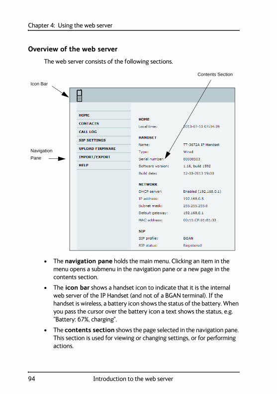
Chapter 4: Using the web server
Overview of the web server
The web server consists of the following sections.
• The navigation pane holds the main menu. Clicking an item in the menu opens a submenu in the navigation pane or a new page in the contents section.
• The icon bar shows a handset icon to indicate that it is the internal web server of the IP Handset (and not of a BGAN terminal). If the handset is wireless, a battery icon shows the status of the battery. When you pass the cursor over the battery icon a text shows the status, e.g. “Battery: 67%, charging”.
• The contents section shows the page selected in the navigation pane. This section is used for viewing or changing settings, or for performing actions.
Navigation
Icon Bar
Pane
Contents Section
94 Introduction to the web server
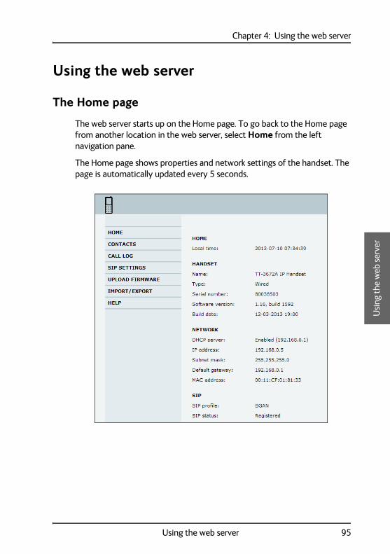
Chapter 4: Using the web server 44
44
Usi
ng th
e w
eb s
erve
r
Using the web server
The Home page
The web server starts up on the Home page. To go back to the Home page from another location in the web server, select Home from the left navigation pane.
The Home page shows properties and network settings of the handset. The page is automatically updated every 5 seconds.
Using the web server 95
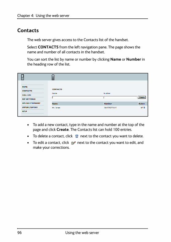
Chapter 4: Using the web server
Contacts
The web server gives access to the Contacts list of the handset.
Select CONTACTS from the left navigation pane. The page shows the name and number of all contacts in the handset.
You can sort the list by name or number by clicking Name or Number in the heading row of the list.
• To add a new contact, type in the name and number at the top of the page and click Create. The Contacts list can hold 100 entries.
• To delete a contact, click next to the contact you want to delete.
• To edit a contact, click next to the contact you want to edit, and make your corrections.
96 Using the web server
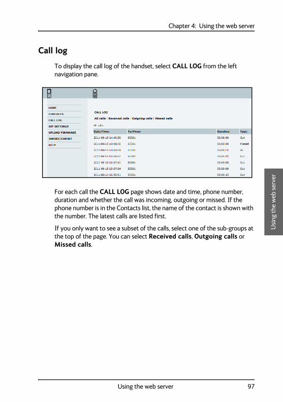
Chapter 4: Using the web server 44
44
Usi
ng th
e w
eb s
erve
r
Call log
To display the call log of the handset, select CALL LOG from the left navigation pane.
For each call the CALL LOG page shows date and time, phone number, duration and whether the call was incoming, outgoing or missed. If the phone number is in the Contacts list, the name of the contact is shown with the number. The latest calls are listed first.
If you only want to see a subset of the calls, select one of the sub-groups at the top of the page. You can select Received calls, Outgoing calls or Missed calls.
Using the web server 97
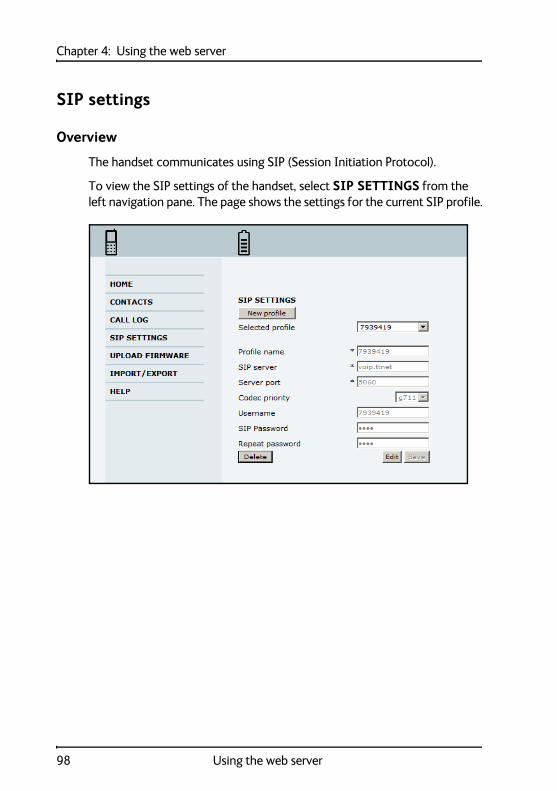
Chapter 4: Using the web server
SIP settings
Overview
The handset communicates using SIP (Session Initiation Protocol).
To view the SIP settings of the handset, select SIP SETTINGS from the left navigation pane. The page shows the settings for the current SIP profile.
98 Using the web server
Chapter 4: Using the web server 44
44
Usi
ng th
e w
eb s
erve
r
To add a new SIP profile
The list of SIP profiles can hold maximum 10 profiles. To add a new profile, do as follows:
1. Click New profile at the top of the page.
2. Fill in the list.
You may not need to fill in all items in the list. Mandatory fields are marked with .
3. Click Save at the bottom of the page.
To edit a SIP profile
To edit a SIP profile, do as follows:
1. From the Profile scroll list select the profile you want to edit.
2. Change the settings according to your needs.
3. Click Save at the bottom of the page.
To delete a SIP profile
To delete a SIP profile, do as follows:
1. From the Profile scroll list select the profile you want to delete.
2. Click Delete at the bottom of the page.
Using the web server 99
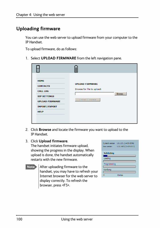
Chapter 4: Using the web server
Uploading firmware
You can use the web server to upload firmware from your computer to the IP Handset.
To upload firmware, do as follows:
1. Select UPLOAD FIRMWARE from the left navigation pane.
2. Click Browse and locate the firmware you want to upload to the IP Handset.
3. Click Upload firmware.The handset initiates firmware upload, showing the progress in the display. When upload is done, the handset automatically restarts with the new firmware.
Note After uploading firmware to the handset, you may have to refresh your Internet browser for the web server to display correctly. To refresh the browser, press <F5>.
100 Using the web server
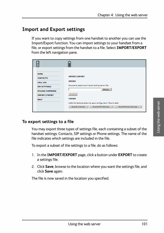
Chapter 4: Using the web server 44
44
Usi
ng th
e w
eb s
erve
r
Import and Export settings
If you want to copy settings from one handset to another you can use the Import/Export function. You can import settings to your handset from a file, or export settings from the handset to a file. Select IMPORT/EXPORT from the left navigation pane.
To export settings to a file
You may export three types of settings file, each containing a subset of the handset settings: Contacts, SIP settings or Phone settings. The name of the file indicates which settings are included in the file.
To export a subset of the settings to a file, do as follows:
1. In the IMPORT/EXPORT page, click a button under EXPORT to create a settings file.
2. Click Save, browse to the location where you want the settings file, and click Save again.
The file is now saved in the location you specified.
Using the web server 101
Chapter 4: Using the web server
To import settings from a file
You can import three types of settings file, each containing a subset of the handset settings: Contacts, SIP settings or Phone settings. The name of the file indicates which settings are included in the file.
To import a settings file, do as follows:
1. Click Browse.
2. Browse to the location where the settings file is saved and select the file you want to import.
3. Click Open.
4. Click Import.
The selected settings are now replaced by the imported settings.
102 Using the web server
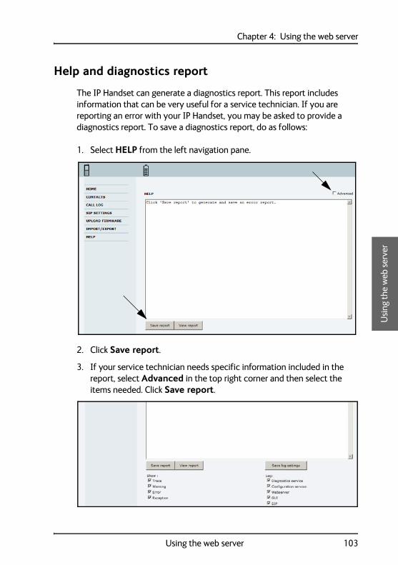
Chapter 4: Using the web server 44
44
Usi
ng th
e w
eb s
erve
r
Help and diagnostics report
The IP Handset can generate a diagnostics report. This report includes information that can be very useful for a service technician. If you are reporting an error with your IP Handset, you may be asked to provide a diagnostics report. To save a diagnostics report, do as follows:
1. Select HELP from the left navigation pane.
2. Click Save report.
3. If your service technician needs specific information included in the report, select Advanced in the top right corner and then select the items needed. Click Save report.
Using the web server 103
Chapter 4: Using the web server
104 Using the web server
Chapter 55
55
Serv
ice
& m
aint
enan
ce
Service & maintenance 5
This chapter gives guidelines for getting support, general maintenance tasks and troubleshooting,
Getting support
If this manual does not provide the information required to solve your problem, you may want to contact your Airtime Provider or your supplier.
If you can see that the problem is related to airtime and not to the IP Handset, please contact your Airtime Provider
If you need assistance with problems caused by the IP Handset, please call a distributor in your area. You may be asked to generate a diagnostics report. For information on how to generate a report, see Help and diagnostics report on page 103.
An updated list of distributors is available on Thrane & Thrane’s web site: thrane.com.
105

Chapter 5: Service & maintenance
Maintenance tasks
Carefully read and follow the instructions on maintenance of the IP Handset. Failure to carefully observe the following procedures and precautions can result in leakage of battery fluid, permanent damage to batteries and serious personal injury!
Software update
For instructions how to make a software update see Uploading firmware on page 100.
Battery handling for the wireless IP Handset
• Do not dismantle, open or shred the IP Handset. It should be dismantled only by trained personnel.1
• Do not expose the IP Handset or batteries to heat or fire. Avoid storage in direct sunlight.
• Do not subject the IP Handset or batteries to mechanical shock.
Leaking battery
In the event of an IP Handset leaking liquid, do not allow the liquid to come into contact with the skin or eyes. If contact has been made, wash the affected area with copious amounts of water and seek medical advice.
1. Exception: You must remove the battery before disposing of the IP Handset. For details how to proceed see To remove the battery from the IP Handset on page 107.
Note If the IP Handset is out of use for a longer period of time, recharge the battery every two years to avoid deterioration of the battery.
106 Maintenance tasks
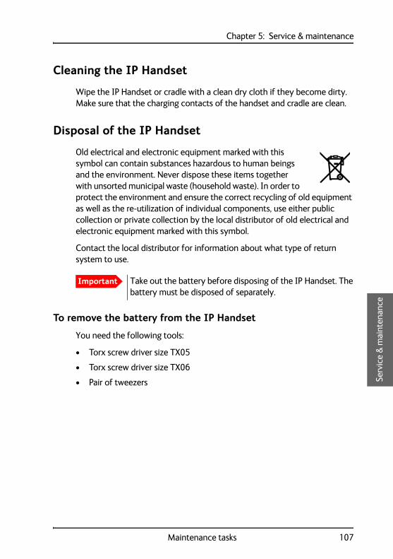
Chapter 5: Service & maintenance5
55
Serv
ice
& m
aint
enan
ce
Cleaning the IP Handset
Wipe the IP Handset or cradle with a clean dry cloth if they become dirty. Make sure that the charging contacts of the handset and cradle are clean.
Disposal of the IP Handset
Old electrical and electronic equipment marked with this symbol can contain substances hazardous to human beings and the environment. Never dispose these items together with unsorted municipal waste (household waste). In order to protect the environment and ensure the correct recycling of old equipment as well as the re-utilization of individual components, use either public collection or private collection by the local distributor of old electrical and electronic equipment marked with this symbol.
Contact the local distributor for information about what type of return system to use.
To remove the battery from the IP Handset
You need the following tools:
• Torx screw driver size TX05
• Torx screw driver size TX06
• Pair of tweezers
Important Take out the battery before disposing of the IP Handset. The battery must be disposed of separately.
Maintenance tasks 107
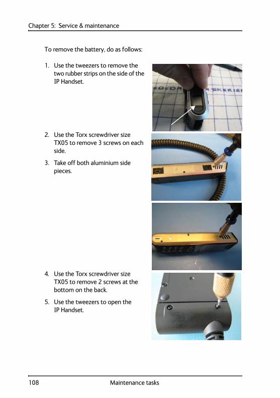
Chapter 5: Service & maintenance
To remove the battery, do as follows:
1. Use the tweezers to remove the two rubber strips on the side of the IP Handset.
2. Use the Torx screwdriver size TX05 to remove 3 screws on each side.
3. Take off both aluminium side pieces.
4. Use the Torx screwdriver size TX05 to remove 2 screws at the bottom on the back.
5. Use the tweezers to open the IP Handset.
108 Maintenance tasks

Chapter 5: Service & maintenance5
55
Serv
ice
& m
aint
enan
ce
6. Use the Torx screwdriver size TX06 to remove 6 screws at the back.
7. Take out the battery. It is glued to the board, you may need to use some force. Tear the flat cable out of the connector.
8. Dispose of the IP Handset and the battery safely according to local laws and regulations.
Maintenance tasks 109
Chapter 5: Service & maintenance
Troubleshooting guide
The below table provides information on some of the problems that might occur, including possible causes and remedies to solve the problems.
Problem Possible Cause Remedy
The handset is not responding to any keys pressed.
An error occurred in the software.
Press and hold the on hook key for at least 10 seconds to switch off the handset. Then switch on the handset again.
No connection to the BGAN network.
1) The PIN code has not been entered in the BGAN terminal,
2) There is an error in the terminal or the BGAN network.
1) Enter the menu system of the handset and select BGAN > Enter PIN code. For information on how to enter the PIN, see Establishing a connection using BGAN terminal on page 20.
2) See the manuals for the BGAN terminal for information on how to troubleshoot errors.
The handset shows “SIP fault”
No SIP profile is selected, the selected SIP profile is invalid, or the user name or password is wrong.
Enter the menu system and select SIP to see the selected profile. Change the profile or select another profile if necessary. For further information, see SIP telephony and profiles on page 79.
110 Troubleshooting guide
Appendix AAAAA
Tech
nica
l spe
cifi
cati
ons
Technical specifications A
This appendix contains specifications and outline drawings for the wired IP Handset and cradle and the wireless IP Handset and cradle.
Thrane IP Handset, wired
Specifications, wired handset
Item Specification
Type TT-3672A Thrane IP Handset, wired
Dimensions (L x B x H) 152 mm x 55 mm x 26.5 mm
Weight 190 g ±20 g (without cable)
Display 2.2", 240 x 320 pixel TFT colour LCD
Operating temperature -25°C to +45°C
Storage and transport temperature
-25°C to +55°C
Humidity Up to 95% without condensation
Air pressure, transport 4572 m AMSL
Power Power over Ethernet (PoE) class 2(Alternative B of IEEE802.3af is not supported.)
Power consumption Max. 7 Watt
Protection category IP55, dust proof and splash proof
LAN interface 10/100 Mbps
111
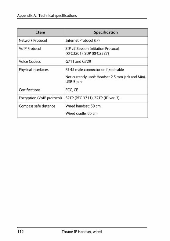
Appendix A: Technical specifications
Network Protocol Internet Protocol (IP)
VoIP Protocol SIP v2 Session Initiation Protocol(RFC3261), SDP (RFC2327)
Voice Codecs G711 and G729
Physical interfaces RJ-45 male connector on fixed cable
Not currently used: Headset 2.5 mm jack and Mini-USB 5-pin
Certifications FCC, CE
Encryption (VoIP protocol) SRTP (RFC 3711), ZRTP (ID ver. 3),
Compass safe distance Wired handset: 50 cm
Wired cradle: 85 cm
Item Specification
112 Thrane IP Handset, wired

Appendix A: Technical specificationsAAAA
Tech
nica
l spe
cifi
cati
ons
Outline dimensions, wired handset
Dimensions are in millimeters
Thrane IP Handset, wired 113
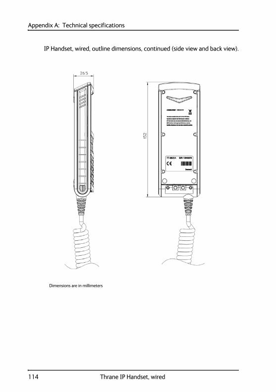
Appendix A: Technical specifications
IP Handset, wired, outline dimensions, continued (side view and back view).
Dimensions are in millimeters
114 Thrane IP Handset, wired
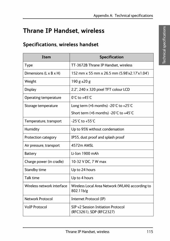
Appendix A: Technical specificationsAAAA
Tech
nica
l spe
cifi
cati
ons
Thrane IP Handset, wireless
Specifications, wireless handset
Item Specification
Type TT-3672B Thrane IP Handset, wireless
Dimensions (L x B x H) 152 mm x 55 mm x 26.5 mm (5.98’x2.17’x1.04’)
Weight 190 g ±20 g
Display 2.2", 240 x 320 pixel TFT colour LCD
Operating temperature 0°C to +45°C
Storage temperature Long term (>6 months) -20°C to +25°C
Short term (<6 months) -20°C to +45°C
Temperature, transport -25°C to +55°C
Humidity Up to 95% without condensation
Protection category IP55, dust proof and splash proof
Air pressure, transport 4572m AMSL
Battery Li-Ion 1900 mAh
Charge power (in cradle) 10-32 V DC, 7 W max
Standby time Up to 24 hours
Talk time Up to 4 hours
Wireless network interface Wireless Local Area Network (WLAN) according to 802.11b/g
Network Protocol Internet Protocol (IP)
VoIP Protocol SIP v2 Session Initiation Protocol(RFC3261), SDP (RFC2327)
Thrane IP Handset, wireless 115
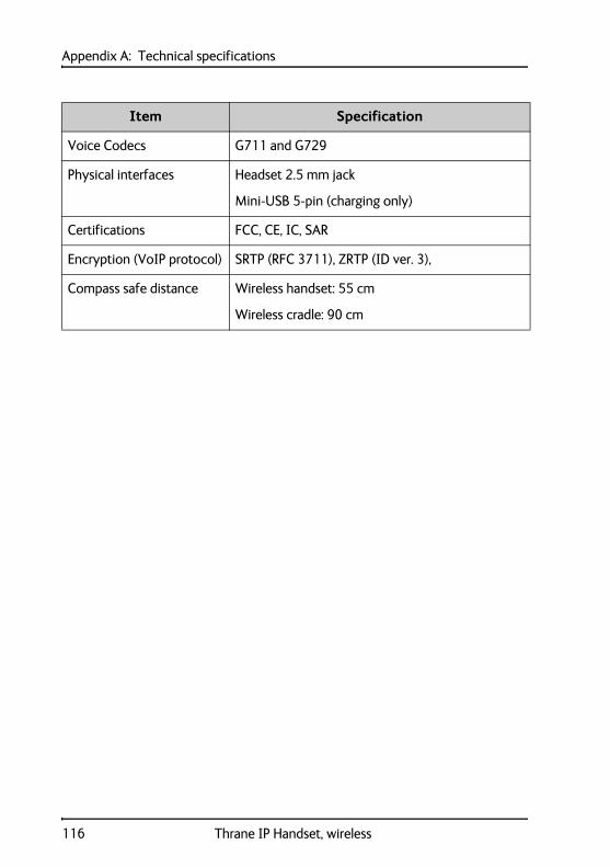
Appendix A: Technical specifications
Voice Codecs G711 and G729
Physical interfaces Headset 2.5 mm jack
Mini-USB 5-pin (charging only)
Certifications FCC, CE, IC, SAR
Encryption (VoIP protocol) SRTP (RFC 3711), ZRTP (ID ver. 3),
Compass safe distance Wireless handset: 55 cm
Wireless cradle: 90 cm
Item Specification
116 Thrane IP Handset, wireless
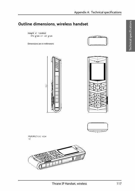
Appendix A: Technical specificationsAAAA
Tech
nica
l spe
cifi
cati
ons
Outline dimensions, wireless handset
Dimensions are in millimeters
Thrane IP Handset, wireless 117
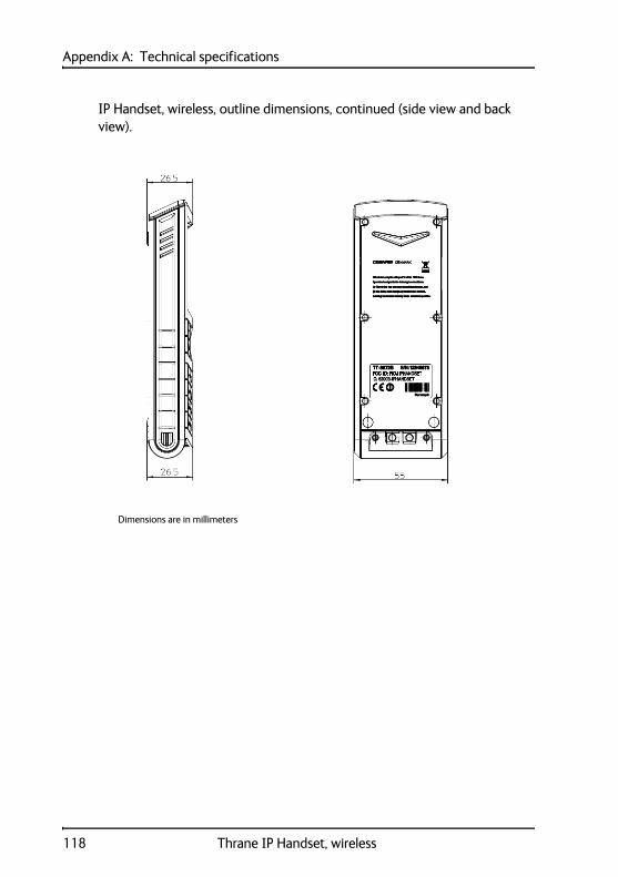
Appendix A: Technical specifications
IP Handset, wireless, outline dimensions, continued (side view and back view).
Dimensions are in millimeters
118 Thrane IP Handset, wireless

Appendix A: Technical specificationsAAAA
Tech
nica
l spe
cifi
cati
ons
Thrane IP cradle outline dimensions
The below drawing applies to both the wired and the wireless variant.
Thrane IP cradle outline dimensions 119
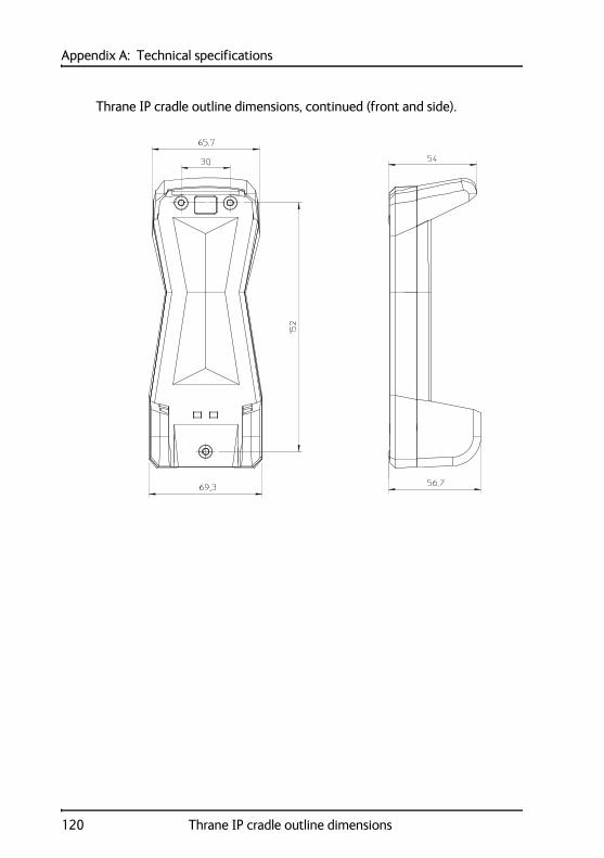
Appendix A: Technical specifications
Thrane IP cradle outline dimensions, continued (front and side).
120 Thrane IP cradle outline dimensions
Appendix BBB
BB
Con
form
ity
Conformity B
Thrane IP Handset, wired
CE (LVD & EMC)
The Thrane IP Handset, wired, is CE certified (LVD &EMC directives) as stated in the “Declaration of Conformity with LVD and EMC Directives”, enclosed in copy on the next page.
FCC
Note: This equipment has been tested and found to comply with the limits for a Class A digital device, pursuant to Part 15 of the FCC Rules. These lim-its are designed to provide reasonable protection against harmful interfer-ence when the equipment is operated in a commercial environment. This equipment generates, uses, and can radiate radio frequency energy and, if not installed and used in accordance with the instruction manual, may cause harmful interference to radio communications. Operation of this equipment in a residential area is likely to cause harmful interference in which case the user will be required to correct the interference at his own expense.
121
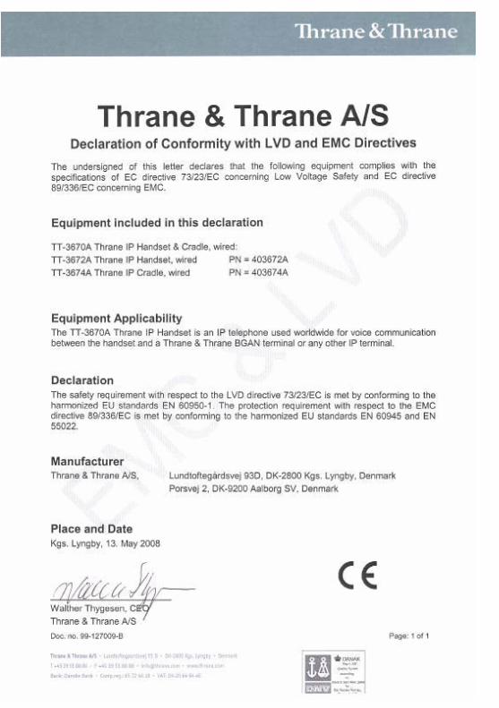
Appendix B: ConformityB
BB
B
Con
form
ity
Thrane IP Handset, wireless
CE (R&TTE)
The IP Handset is CE certified (R&TTE directive) as stated in "Declaration of Conformity with R&TTE Directive", enclosed in electronic copy on the next page.
Use of WLAN
The WLAN interface requires that the user enters the current country of operation. See To set the country for Wireless network use on page 67.
For use in the EU, the following restrictions apply:
• France: Outdoor use must be limited to 10 mW EIRP within the frequency band 2454 MHz to 2483.5 MHz.
• Italy: Outdoor use outside own premises require general authorization
FCC
Note: This equipment has been tested and found to comply with the limits for a Class B digital device, pursuant to part 15 of the FCC Rules. These limits are designed to provide reasonable protection against harmful interference in a residential installation. This equipment generates, uses and can radiate radio frequency energy and, if not installed and used in accordance with the instructions, may cause harmful interference to radio communications. However, there is no guarantee that interference will not occur in a particular installation. If this equipment does cause harmful interference to radio or television reception, which can be determined by turning the equipment off and on, the user is encouraged to try to correct the interference by one or more of the following measures:
• Reorient or relocate the receiving antenna.
• Increase the separation between the equipment and receiver.
• Connect the equipment into an outlet on a circuit different from that to which the receiver is connected.
Thrane IP Handset, wireless 123
Appendix B: Conformity
• Consult the dealer or an experienced radio/TV technician for help.
See also the FCC/IC Notice on the next page.
Part 15.21
Changes or modifications not expressly approved by the party responsible for compliance could void the user's authority to operate the equipment.
124 Thrane IP Handset, wireless
Appendix B: ConformityB
BB
B
Con
form
ity
FCC/IC Notice
To comply with FCC radiation exposure requirements, use of this device for head body operational configurations is limited to tested configurations and approved by Thrane & Thrane A/S.
THIS MODEL DEVICE MEETS THE GOVERNMENT'S REQUIREMENTS FOR EXPOSURE TO RADIO WAVES.
Your wireless device is a radio transmitter and receiver. It is designed and manufactured not to exceed the emission limits for exposure to radio frequency (RF) energy set by the Federal Communications Commission of the U.S. Government. These limits are part of comprehensive guidelines and establish permitted levels of RF energy for the general population. The guidelines are based on standards that were developed by independent scientific organizations through periodic and thorough evaluation of scientific studies. The standards include a substantial safety margin designed to assure the safety of all persons, regardless of age and health.
The exposure standard for wireless devices employs a unit of measurement known as the Specific Absorption Rate, or SAR. The SAR limit set by the FCC is 1.6W/kg. Tests for SAR are conducted using standard operating positions specified by the FCC with the device transmitting at its highest certified power level in all tested frequency bands. Although the SAR is determined at the highest certified power level, the actual SAR level of the device while operating can be well below the maximum value. Before a device model is available for sale to the public, it must be tested and certified to the FCC that it does not exceed the limit established by the government-adopted requirement for safe exposure. The tests are performed in positions and locations (e.g., next to the head and body) as required by the FCC for each model. The FCC has granted an Equipment Authorization for this model device with all reported SAR levels evaluated as in compliance with the FCC RF emission guidelines. SAR information on this model device is on file with the FCC and can be found under the Display Grant section http://www.fcc.gov/oet/fccid after searching on FCC ID: ROJIPHANDSET.
Thrane IP Handset, wireless 125
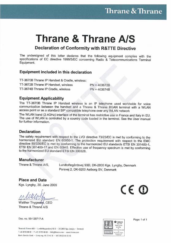
GlossaryCC
Glossary CCC
Glo
ssar
y
A
AES Advanced Encryption Standard
B
BGAN Broadband Global Area Network. A mobile satellite service that offers high-speed data up to 492 kbps and voice telephony. BGAN enables users to access e-mail, corporate networks and the Internet, transfer files and make telephone calls.
C
CE Conformitée Européenne. This term signifies that a CE certified product conforms to European health, environmental, and safety regulations. It makes the product legal to be sold in the European Union.
D
DHCP Dynamic Host Configuration Protocol. A protocol for assigning dynamic IP addresses to devices on a network. With dynamic addressing, a device can have a different IP address every time it connects to the network.
DNS Domain Name Server. A system translating server names (URLs) to server addresses.
I
IEEE Institute of Electrical and Electronics Engineers. IEEE is a non-profit organization and the world’s leading professional association for the advancement of technology.
127
Glossary
IMSO International Mobile Satellite Organisation. An intergovernmental organisation that oversees certain public satellite safety and security communication services provided via the Inmarsat satellites.
IP Internet Protocol. The method or protocol by which data is sent from one computer to another on the Internet.
L
LAN Local Area Network
LCD Liquid Crystal Display
M
MAC Media Access Control address. A hardware address that uniquely identifies each node of a network.
N
NAT Network Address Translation.
P
PCB Printed Circuit Board
PIN Personal Identification Number. A secret numeric password shared between a user and a system, used to authenticate the user to the system.
PoE Power over Ethernet. A standard for combining power supply with transmission of data over the Ethernet. The source unit "injects" power into the Ethernet cable and the power is "picked up" at the connected device.
PSK Pre-Shared Key
128
Glossary CC
CC
Glo
ssar
y
PUK PIN Unblocking Key. An eight-digit code used to unblock a SIM card after three incorrect PINs have been entered. The PUK code is supplied with the SIM card.
Q
QVGA Quarter Video Graphics Array. A popular term for a computer display with 320 × 240 resolution. QVGA displays are often seen in mobile phones, PDAs and some handheld game consoles.
R
RTP Real-time Transport Protocol, defines a standardized packet format for delivering audio and video over the Internet.
S
SA Stronger Authentication
SIM Subscriber Identity Module.The SIM provides secure storing of the key identifying a mobile phone service subscriber but also subscription information, preferences and storage of text messages.
SIP Session Initiation Protocol. An application-layer control (signalling) protocol for creating, modifying, and terminating sessions with one or more participants. Used e.g. for Internet telephony.
SOLAS (International convention for the) Safety Of LIfe At Sea. Generally regarded as the most important of all international treaties concerning the safety of merchant ships.
STUN Simple Traversal of UDP through NATs, a protocol for assisting devices behind a NAT firewall or router with their packet routing.
129
Glossary
T
TFT Thin Film Transistor. A display type using a number of individual display cells, each controlled by its own transistor.
TKIP Temporal Key Integrity Protocol
U
URL Uniform Resource Locator. A name used to describe the address of a specific resource on the internet.
USB Universal Serial Bus. A serial bus standard to interface devices.
V
VoIP Voice over Internet Protocol. The routing of voice conversations over the Internet or through an IP-based network.
W
WEP Wired Equivalent Privacy, a security protocol for wireless networks that encrypts transmitted data.
WLAN Wireless Local Area Network
WPA Wi-Fi Protected Access, wireless security with greater protection than WEP.
Z
ZRTP ZRTP is a cryptographic key-agreement protocol to negotiate the keys to encrypt VoIP phone calls. ZRTP describes a method of Diffie-Hellman key agreement for Secure Real-time Transport Protocol (SRTP).
130
IndexD
Index D
DD
D
Inde
x
Numerics
3.1 kHz Audio number, 46501 phone number
data connections, 85870, call, 46
A
active alarmsBGAN, 89
adjustbacklight, 72sound, 69standby backlight, 72volume during call, 52
alarmactive BGAN, 89alert BGAN, 88
answer when lifted, 71audio
suppress, 69authentication, 50auto power off, 73auto power on, 74automatic IP address, 67automatic secure, 49automatic shut down, 73
B
backlight, 72adjust, 72standby, adjust, 72suppress, 69
batterycharging, 17charging interval, storage, 18, 106dispose of, 107leak, 106remove, 107stand-by time, 4
BGANcall using, 46enter PIN, 88menu, 86status information, 87
BGAN critical alarms, 89BGAN software version, 87BGAN terminal, 24
configuration, 48setup, 24
BGAN terminal type, 87
C
cable relief, 9call
+870, 46encrypted, 47ending or rejecting, 46from BGAN terminal, 46making, 25, 38receiving, 40secure, 47transferring, 40
call log, 97add number to contacts, 57delete a number, 58delete all numbers, 58manage, 57memory usage, 58
131
Index
call services, 70CE compliance, 121
wired handset, 121wireless handset, 123
change hands-free mode, 52charging
connector, 14USB charger, 17wireless handset, 17
clear logautomatically, 73
CNo, 87codec
G711, 82G729, 82
codec prioritySIP profile, 82
compass safe distancewired handset, 112wireless handset, 116
configurationBGAN terminal, 48
configureweb interface, 24
confirm SAS, 50conformity
wired, 121wireless, 123
connect external power supply, 15connecting
BGAN terminal, 11connecting cradle
LAN cable, 9connecting the handset, 8connection, start
IP background, 86IP streaming, 86
connectorcradle, 8
132
connectors, 8contact information, 105Contacts
clear automatically on startup, 73contacts, 59
add, 59, 96call, 59delete, 60, 96display, 59edit, 60, 96
control functionsBGAN terminal, 1
control keys, 27cradle
connector, 8detection, 71dimensions, 119installing, 10measures, 10outline, 119
critical alarmdisplay, 88
D
date and time setting, 75day/night mode, automatic, 72Declarations of Conformity
wired, 122wireless, 126
Default gatewayshow, 61
default settings, 78DHCP, 67diagnostics report, 103dialled number, 57
Index DD
DD
Inde
x
dimensionscradle, 119handset, 113
displayicons, 34night colours, 53overview, 32settings, 72
disposalbattery, 107IP Handset, 107rules for, iii
Distresscall, 2, 90test, 2, 90
DNSprimary and secondary, enter, 68
document numberthis manual, i
E
encrypted call, 47encryption
protocol, 112secure call, verify, 50setup, 70verification, 50
external power supply, 14
F
factory default, 78fail
secure call, 51FCC compliance, 121
wired handset, 121wireless handset, 123
features, 5firmware
uploading, 100
G
G711 codec, 82G729 codec, 82gateway
enter, 68go secure, 49GPS position, 87
H
hand-held mode, 52handset, 23
connecting, 8connecting to BGAN terminal, 11dimensions, 113features, 5outline, 113PIN, 76register, 20, 23
hands-freechange mode, 52operation, 52
headset, 55help, 103
I
icons in display, 34identification of the handset, 95import/export settings, 101installation
cradle, 10
133

Index
IP addressautomatic, 67DHCP, 67show, 61, 93static, 67
IP backgroundstart connection, 86
IP Handsetgetting to know, 1setup, 23switch off, 12switch on, 12
IP mode, 67IP streaming
start connection, 86
K
key negotiation, secure call, 50keypad
alpha-numeric keys, 29click, 69control keys, 27description, 26locking, 53shortcuts, 31
keystext and symbols, 29
L
LAN cable, 9leaking battery, 106local number, 23
BGAN terminal, 23locking the keypad, 53log
clear automatically on startup, 73
134
lowercase mode, 29
M
MAC address, 61make a call, 25, 38manual
document number, imemory usage
call log, 58menu overview, 56menus
main, 32microphone, muting, 53missed calls, 57mobile number, 46muting the microphone, 53
N
network information, 95network settings
wireless, 62night mode, 53
automatic switch to, 72noise cancellation, 70number mode, 29
O
outlinecradle, 119handset, 113
Index DD
DD
Inde
x
P
passwordSIP client, 82
phone book, 59, 96Phone settings, 68physical address
IP Handset, 61PIN
BGAN, 88for handset, 76wrong PIN, 22
PIN status, 87PoE standard, 11port number, 81power
connect to cradle, 15off, 12off, automatic, 73on, 12on, automatic, 74on, off, 26stand by, 4
Power over Ethernetstandard, 11
power supply, 14PUK code, 22
R
received calls, 57register
handset, 20, 23remove battery, 107reregister
SIP server, 82reset, 78restore factory settings, 78
ringing tone, 69router configuration, 48RTP streaming, 48
S
safetycall, 2, 90voice, 2, 90
safety callicon, 34
safety summary, iiiSAS, 50SAS confirmation, 50screensaver, 36, 72secure call, 47
automatic, 49, 70confirm, 50failed, 51how to start, 49setup, 49single call, 49
select a SIP profile, 79serial number, 61set up, 24
IP Handset, 23Short Authentication String, 50shut down
automatic, 73signal strength, 87SIP client, 79
password, 82user name, 82
SIP fault, 110
135
Index
SIP profiles, 98activating, 79adding, 80, 99codec priority, 82deleting, 83, 99editing, 83, 99selecting, 79
SIP requirements, 48SIP server, 80
name, 81port number, 81reregister, 82STUN, 82
SIP Service Providerrequirements, 48
SIP telephony, 79software error, 110software upload, 100software version
BGAN terminal, 87IP Handset, 61, 95
soundadjust, 69
specifications, 111SSID, 64standard voice number, 46standby backlight, 72stand-by time, 4start secure call, 49startup options, 73static IP address, 67Status, 87status, 95stealth mode
on, off, 69quick setting, 54setting up, 69
streaming connectionstart, 86
136
STUN serverSIP server, 82
Subnet mask addressshow, 61
support, 105diagnostics report, 103
switch offIP Handset, 12
switch onIP Handset, 12
T
technical specifications, 111terminal type, BGAN, 87test
Voice Distress, 90text mode, 29text, writing in display, 54time setting, 75tone volume, 69transfer a call, 40transparency, 72troubleshooting guide, 110typography used in this manual, v
U
unlock, 22uploading firmware, 100uppercase mode, 29USB
charger, 17charging connector, 14
user interfaces, 37user name
SIP client, 82
Index DD
DD
Inde
x
V
verify secure call, 50Voice Distress, 2, 47
icon, 34test, 85
Voice Distress test, 90VoIP protocol, 112volume
adjusting during call, 52up or down, 28
W
web serveraccessing, 93browser settings, 92call log, 97contacts, 96enabling or disabling, 74Home, 95import/export settings, 101introduction, 91overview, 94SIP settings, 98using, 91
wired handsetgetting started, 7
wirelessstandard, 14
wireless access pointconnecting the IP Handset, 19connection, 14
wireless handsetgetting started, 7
Wireless network useset country, 67
WLANconnecting, 62editing profile, 64standard, 14
writing text in display, 54
X
X-Stream, 85
Z
ZRTP protocolsecure call, 48
137

98-126059-I
www.cobham.com/satcom