Thermo Scientific AquaSensors AV38 and DataStick ….pdf · 7.2.1 SLC 5/03 and SLC 5/04 PLCs ......
88
Thermo Scientific AquaSensors ™ AV38 and DataStick ™ Ethernet Communications User Guide
Transcript of Thermo Scientific AquaSensors AV38 and DataStick ….pdf · 7.2.1 SLC 5/03 and SLC 5/04 PLCs ......

Thermo Scientific AquaSensors™ AV38 and DataStick™ Ethernet Communications User Guide

ROSS and the COIL trade dress are trademarks of Thermo Fisher Scientific Inc. U.S. patent 6,793,787.
AQUAfast, Cahn, ionplus, KNIpHE, No Cal, ORION, perpHect, PerpHecT, PerpHecTion, pHISA, pHuture, Pure Water, Sage, Sensing the Future, SensorLink, ROSS, ROSS Ultra, Sure-Flow, Titrator PLUS and TURBO2 are registered trademarks of Thermo Fisher.
1-888-pHAX-ION, A+, All in One, Aplus, AQUAsnap, AssuredAccuracy, AUTO-BAR, AUTO-CAL, AUTO DISPENSER, Auto-ID, AUTO-LOG, AUTO-READ, AUTO-STIR, Auto-Test, BOD AutoEZ, Cable-Free, CERTI-CAL, CISA, DataCOLLECT, DataPLUS, digital LogR, DirectCal, DuraProbe, Environmental Product Authority, Extra Easy/Extra Value, FAST QC, GAP, GLPcal, GLPcheck, GLPdoc, ISEasy, KAP, LabConnect, LogR, Low Maintenance Triode, Minimum Stir Requirement, MSR, NISS, One-Touch, One-Touch Calibration, One-Touch Measurement, Optimum Results, Orion Star, Pentrode, pHuture MMS, pHuture Pentrode, pHuture Quatrode, pHuture Triode, Quatrode, QuiKcheK, rf link, ROSS Resolution, SAOB, SMART AVERAGING, Smart CheK, SMART STABILITY, Stacked, Star Navigator 21, Stat Face, The Enhanced Lab, ThermaSense, Triode, TRIUMpH, Unbreakable pH, Universal Access are trademarks of Thermo Fisher.
Guaranteed Success and The Technical Edge are service marks of Thermo Fisher.
PerpHecT meters are protected by U.S. patent 6,168,707.
PerpHecT ROSS electrodes are protected by U.S. patent 6,168,707.
ORION Series A meters and 900A printer are protected by U.S. patents 5,198,093, D334,208 and D346,753.
ionplus electrodes and Optimum Results solutions are protected by U.S. patent 5,830,338.
ROSS Ultra electrodes are protected by U.S. patent 6,793,787.
ORP standard is protected by U.S. patent 6,350,367.
No Cal electrodes are protected by U.S. patent 7,276,142.
© 2009 Thermo Fisher Scientific Inc. All rights reserved. All trademarks are the property of Thermo Fisher Scientific Inc. and its subsidiaries.
The specifications, descriptions, drawings, ordering information and part numbers within this document are subject to change without notice.
This publication supersedes all previous publications on this subject.

Thermo Scientific AquaSensors™ DataStick™ Ethernet Communications User Guide 1
Table of Contents 1 Quick Start .................................................................................................................. 6 2 Introduction................................................................................................................. 7 3 Hardware Setup........................................................................................................... 9
3.1 Ethernet Communications Adapter................................................................... 10 3.1.1 Operating Temperature ............................................................................. 11 3.1.2 Electrical Connections .............................................................................. 12 3.1.3 Location of Adapter’s MAC Address ....................................................... 12 3.1.4 LED Indicators.......................................................................................... 13 3.1.5 Restoring Default IP Address, Subnet Mask, Gateway Address .............. 14
3.2 AV38 Local Display with Ethernet Option ...................................................... 15 3.2.1 Electrical Connections .............................................................................. 15 3.2.2 Location of AV38’s MAC Address .......................................................... 15 3.2.3 Restoring Default IP Address, Subnet Mask, Gateway Address .............. 16
4 Configuration Procedures ......................................................................................... 17 4.1 For Evaluation/Demonstration Purposes .......................................................... 19
4.1.1 Advanced Configuration........................................................................... 23 4.2 Commissioning an Ethernet Product for Service.............................................. 25
5 Web Server................................................................................................................ 37 5.1 Home Page ........................................................................................................ 37 5.2 Calibration Page................................................................................................ 38 5.3 Configuration Page ........................................................................................... 39 5.4 Communications Settings Page ........................................................................ 41
5.4.1 Viewing/Changing the Communications Settings .................................... 41 5.4.2 Viewing/Clearing the Internal Counters ................................................... 41 5.4.3 Upgrading the Firmware ........................................................................... 42
6 EtherNet/IP ............................................................................................................... 43 6.1 Electronic Data Sheet (EDS) ............................................................................ 43 6.2 Definitions......................................................................................................... 43 6.3 Reference Documents ....................................................................................... 43 6.4 Open DeviceNet Vendor Association, Inc. (ODVA)........................................ 44 6.5 Object Model .................................................................................................... 44
6.5.1 Configuration ............................................................................................ 44 6.5.2 Identity Object (01HEX – 1 Instance) ......................................................... 44 6.5.3 Message Router Object (02HEX – 0 Instances) .......................................... 45 6.5.4 Assembly Object (04HEX – 2 Instances).................................................... 45 6.5.5 Connection Manager Object (06HEX) ........................................................ 46 6.5.6 TCP Object (F5HEX – 1 Instance).............................................................. 46 6.5.7 Ethernet Link Object (F6HEX – 1 Instance) ............................................... 47 6.5.8 System Status Object (64HEX – 1 Instance)............................................... 48 6.5.9 Sensor Installation Object (65HEX – 1 Instance) ....................................... 49 6.5.10 Sensor Value Object (66HEX – 1 Instance) ................................................ 50 6.5.11 User Configuration Object (67HEX – 1 Instance) ...................................... 50 6.5.12 Generic Sensor Calibration Object (68HEX – 1 Instance).......................... 51

Thermo Scientific AquaSensors™ DataStick™ Ethernet Communications User Guide 2
6.5.13 Conductivity Sensor Calibration Object (69HEX – 1 Instance).................. 52 6.5.14 Mode Configuration Object (75HEX – 1 Instance)..................................... 53
6.6 EtherNet/IP Reference ...................................................................................... 53 7 Modbus TCP and PCCC ........................................................................................... 54
7.1 Modbus TCP ..................................................................................................... 54 7.1.1 Modbus TCP Reference............................................................................ 55
7.2 Programmable Controller Communication Commands (PCCC)...................... 55 7.2.1 SLC 5/03 and SLC 5/04 PLCs .................................................................. 56 7.2.2 Example SLC 5/03 Ladder Logic Programs............................................. 58 7.2.3 SLC 5/05 PLC........................................................................................... 68 7.2.4 Example SLC 5/05 Ladder Logic Programs............................................. 69 7.2.5 PCCC References...................................................................................... 70
7.3 Modbus TCP and PCCC Register Map ............................................................ 71 8 Certifications............................................................................................................. 82 9 General References ................................................................................................... 82 10 Limited Warranty.................................................................................................. 83 11 Terms and Conditions ........................................................................................... 84

Thermo Scientific AquaSensors™ DataStick™ Ethernet Communications User Guide 3
Table of Figures Figure 1: A diagram of an isolated Ethernet DataStick network. ...................................... 6 Figure 2: A diagram of an isolated AV38 network............................................................ 6 Figure 3: The Ethernet Communications Adapter. ............................................................ 7 Figure 4: The Ethernet option in the AV38 Local Display (front and rear views)............ 7 Figure 5: Dimensions of the Adapter................................................................................. 8 Figure 6: Ethernet Communications Adapter shown detached from a DataStick with a toroidal Sensor Head........................................................................................................... 8 Figure 7: Endpoint power sourcing equipment, Mode A. The product is the Powered End Station.......................................................................................................................... 9 Figure 8: Endpoint power sourcing equipment, Mode B. The product is the Powered End Station........................................................................................................................ 10 Figure 9: The three parts of the DataStick measurement system..................................... 10 Figure 10: The elements of the DataStick Measurement System. ................................... 11 Figure 11: The different parts of the Adapter. ................................................................. 11 Figure 12: RJ45 plug pin positions .................................................................................. 12 Figure 13: LED indicators on the Adapter. Note that the Heartbeat LED is recessed while the Link/Activity LED is not. ................................................................................. 13 Figure 14: Pin numbering and LED locations. ................................................................ 14 Figure 15: The AV38's MAC address is in the lower right-hand corner of the overlay.. 15 Figure 16: Restoring default communications settings of an Adapter embedded inside an AV38................................................................................................................................. 16 Figure 17: A power injector............................................................................................. 19 Figure 18: An Ethernet DataStick network for evaluation or demonstration purposes... 19 Figure 19: An AV38 network for evaluation or demonstration purposes. ...................... 20 Figure 20: Network Connections window. ...................................................................... 20 Figure 21: Local Area Connection Properties. ................................................................ 21 Figure 22: The Internet Protocol (TCP/IP) Properties window. ...................................... 21 Figure 23: Giving the laptop a static IP address. ............................................................. 22 Figure 24: The Ethernet DataStick's Home Page............................................................. 23 Figure 25: Obtaining an IP address automatically........................................................... 24 Figure 26: The alternate configuration settings. .............................................................. 24 Figure 27: The output of the ipconfig command. ...................................................... 25 Figure 28: An Ethernet DataStick network constructed with a power injector and a cross-over cable. ......................................................................................................................... 26 Figure 29: An AV38 network constructed with a power injector and a cross-over cable............................................................................................................................................ 26 Figure 30: An Ethernet DataStick network constructed with an Ethernet switch and patch cables................................................................................................................................. 27 Figure 31: An AV38 network constructed with an Ethernet switch and patch cables. ... 27 Figure 32: An Ethernet DataStick network constructed with a PoE switch and a patch cable. ................................................................................................................................. 28 Figure 33: An AV38 network constructed with a PoE switch and patch cables. ............ 28 Figure 34: Network Connections window. ...................................................................... 29

Thermo Scientific AquaSensors™ DataStick™ Ethernet Communications User Guide 4
Figure 35: Local Area Connection Properties. ................................................................ 29 Figure 36: The Internet Protocol (TCP/IP) Properties window. ...................................... 30 Figure 37: Giving the computer a static IP address. ........................................................ 30 Figure 38: Verifying that no device is present using the ping command...................... 31 Figure 39: The Ethernet DataStick's Home Page............................................................. 32 Figure 40: The product's IP Setup Page........................................................................... 33 Figure 41: Entering the username and password in the IP Setup Page............................ 34 Figure 42: The IP address, subnet mask and gateway address edited as desired............. 35 Figure 43: The Home Page as seen from the Product's new IP address. ......................... 36 Figure 44: The DataStick Measurement System Home Page.......................................... 37 Figure 45: Accessing the Calibration Page...................................................................... 38 Figure 46: The DataStick Measurement System Calibration Page.................................. 38 Figure 47: Accessing the Configuration Edit Page.......................................................... 39 Figure 48: The Configuration Edit Page.......................................................................... 40 Figure 49: The Communications Settings Page............................................................... 41 Figure 50: SLC 5/03 PLC connected to Ethernet network via a 1761-NET-ENI. .......... 56 Figure 51: The ENI Configuration Utility. ...................................................................... 57 Figure 52: The Com Port Redirector. .............................................................................. 58 Figure 53: The Message Routing tab of the ENI Configuration Utility. ......................... 59 Figure 54: Part 1 of 3 of a ladder logic program that reads the Sensor Value from N20:01............................................................................................................................... 60 Figure 55: Part 2 of 3 of a ladder logic program that reads the Sensor Value from N20:01............................................................................................................................... 61 Figure 56: Part 3 of 3 of a ladder logic program that reads the Sensor Value from N20:01............................................................................................................................... 62 Figure 57: The Setup screen for a MSG instruction in a SLC 5/03................................. 62 Figure 58: The Sensor Value in F8:0............................................................................... 63 Figure 59: Part 1 of 3 of a ladder logic program to read and write the Sensor Filter value at N30:18........................................................................................................................... 64 Figure 60: Part 2 of 3 of a ladder logic program to read and write the Sensor Filter value at N30:18........................................................................................................................... 65 Figure 61: Part 3 of 3 of a ladder logic program to read and write the Sensor Filter value at N30:18........................................................................................................................... 66 Figure 62: The Setup screen for a MSG instruction in a SLC 5/03................................. 67 Figure 63: The N7 register showing the Sensor Filter value and the new Sensor Filter value.................................................................................................................................. 68 Figure 64: SLC 5/05 PLC connected directly to an Ethernet network. ........................... 68 Figure 65: The Setup screen for a MSG instruction in a SLC 5/05 PLC......................... 69 Figure 66: Specifying the IP address of the Ethernet product on the Setup screen of the SLC 5/05 MSG instruction. .............................................................................................. 70 Figure 67: The top entry is the Modbus TCP register and the bottom entry is the PCCC register............................................................................................................................... 71

Thermo Scientific AquaSensors™ DataStick™ Ethernet Communications User Guide 5
Table of Tables Table 1: RJ45 connector pin assignment ......................................................................... 12 Table 2: RJ45 jack signal names and functions ............................................................... 15 Table 3: These objects are identical in the Ethernet products and DeviceNet Adapter object models. ................................................................................................................... 44 Table 4: Uptime registers................................................................................................. 71 Table 5: Register bank 1000; status registers. ................................................................. 72 Table 6: Register bank 2000; floating-point registers...................................................... 72 Table 7: Register bank 3000; integer registers. ............................................................... 74 Table 8: Register bank 4000; integer scale-factor registers............................................. 77 Table 9: Register bank 5000; information registers......................................................... 80 Table 10: Register bank 6000; AV38 configuration register........................................... 81 Contact Information To contact Thermo Scientific AquaSensors Technical Support: Within the United States call 1.800.225.1480 or fax 978-232-6015. Outside the United States call 978.232.6000 or fax 978.232.6031. In Europe, the Middle East and Africa, contact your local authorized dealer. Visit us on the web at www.thermo.com/processwater Ethernet Communications Adapter Part Numbers (for use with the DataStick)
• CA17R: 316 Stainless Steel Housing • CA27R: CPVC Housing • CA37R: PEEK® Housing
AV38 with Ethernet Part Number
AV38WX7Z: The variables W, X and Z are for specifying current output, relay and mounting options. The number 7 indicates that the Ethernet option is present.
Thermo Scientific AquaSensors™ DataStick™ Ethernet Communications User Guide 6
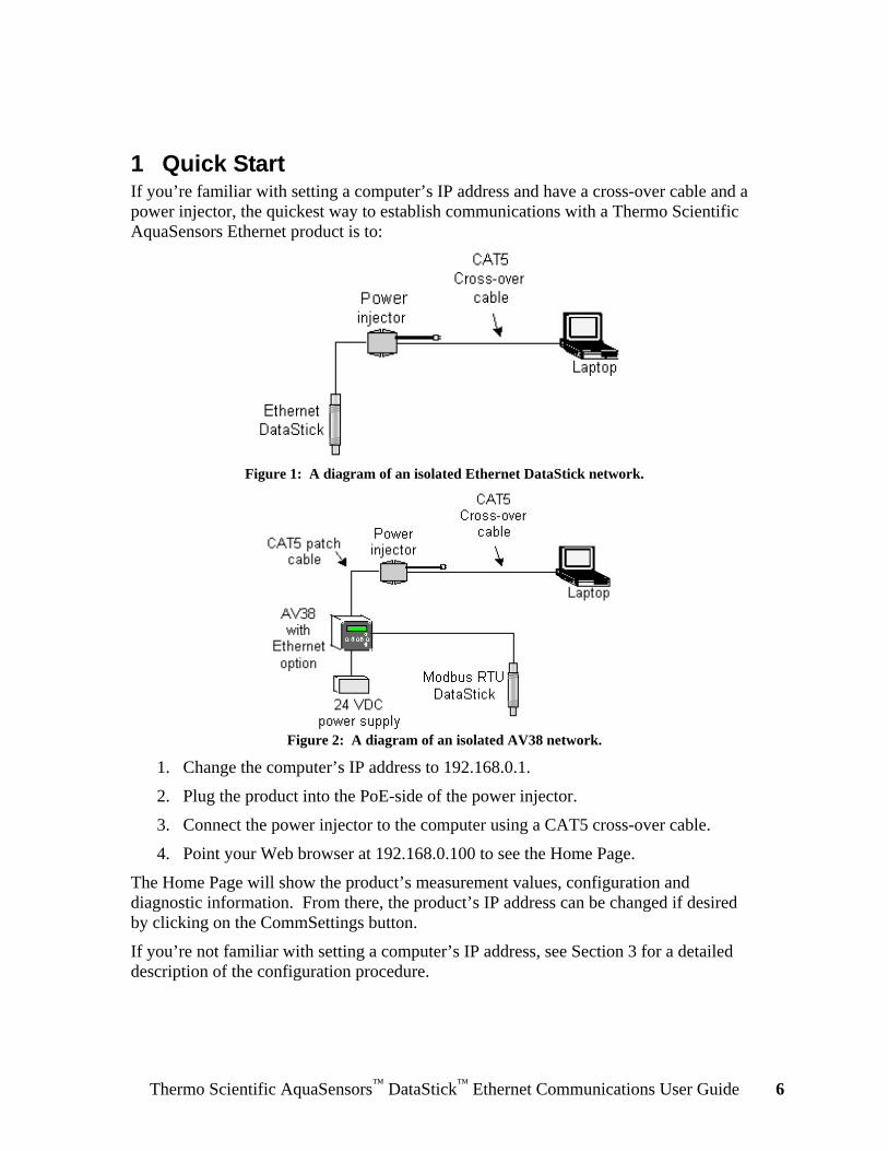
1 Quick Start If you’re familiar with setting a computer’s IP address and have a cross-over cable and a power injector, the quickest way to establish communications with a Thermo Scientific AquaSensors Ethernet product is to:
Figure 1: A diagram of an isolated Ethernet DataStick network.
Figure 2: A diagram of an isolated AV38 network.
1. Change the computer’s IP address to 192.168.0.1.
2. Plug the product into the PoE-side of the power injector.
3. Connect the power injector to the computer using a CAT5 cross-over cable.
4. Point your Web browser at 192.168.0.100 to see the Home Page.
The Home Page will show the product’s measurement values, configuration and diagnostic information. From there, the product’s IP address can be changed if desired by clicking on the CommSettings button.
If you’re not familiar with setting a computer’s IP address, see Section 3 for a detailed description of the configuration procedure.

Thermo Scientific AquaSensors™ DataStick™ Ethernet Communications User Guide 7
2 Introduction This document describes the configuration and operation of the Thermo Scientific AquaSensors Ethernet Communications product. It applies to V1.02.00 firmware or later.
The product is offered in two forms. The first form is as a Communications Adapter as shown in Figure 3 that is plugged into the DataStick Body.
Figure 3: The Ethernet Communications Adapter.
The second form is as an option in the AV38 Local Display as shown in Figure 4.
Figure 4: The Ethernet option in the AV38 Local Display (front and rear views).
The product provides full-featured measurement, configuration, calibration and diagnostics of any DataStick™ measurement system from any Ethernet-enabled device via resident Web pages, EtherNet/IP, Modbus TCP, or Programmable Controller Communication Commands (PCCC). An intermediate analyzer is not required.

Thermo Scientific AquaSensors™ DataStick™ Ethernet Communications User Guide 8
In either form, the product supports the following protocols:
• EtherNet/IP • Modbus TCP • Programmable Controller Communication Commands (PCCC) • TCP/IP (IPv4) • UDP • ICMP (for ping response) • TFTP (for upgrading firmware)
The Ethernet Communications Adapter (Adapter) has a diameter of about 1 inch, a length of about 4.5 inches, and it protrudes from the end of the DataStick Body by about 3.1 inches as shown in Figure 5.
Figure 5: Dimensions of the Adapter.
It has an integral CAT5 industrial Ethernet cable with an RJ45 connector on one end that can be plugged in to any PoE switch or power injector. On the other end of the Adapter is a keyed O-ring-sealed connector that can be plugged into any Thermo Scientific AquaSensors DataStick. There are red and green LED indicators on this end of the Adapter that make it easy to know when the Ethernet link is active. The cable can be up to 100 meters (328 feet) long although we recommend that the Adapter be ordered with 10–30 feet of cable to reduce cost.
When plugged into a DataStick sensor system the Adapter becomes an integral part of the measurement system and the system can be mounted as any industrial sensor would be mounted for continuous use in process applications. Figure 6 shows an Adapter detached from a DataStick with a toroidal Sensor Head.
Figure 6: Ethernet Communications Adapter shown detached from a DataStick with a toroidal
Sensor Head.
The Adapter can be used for direct access to DataStick measure, calibrate, configure and diagnose information, even when the Sensor Head is changed from one type of analytical measurement to another with power applied. The DataStick automatically supports multiple measurement types and all Sensor Heads are automatically supported.

Thermo Scientific AquaSensors™ DataStick™ Ethernet Communications User Guide 9
Refer to the DataStick Manual for detailed information on installation, maintenance and operation of sensors.
The Ethernet option in the AV38 Local Display provides an RJ45 jack for connection to a power injector or 802.3af-compliant (PoE) Ethernet hub or switch as shown on the right side of Figure 4. It allows network access to the Modbus RTU DataStick connected to the AV38.
In this form, power for the Ethernet option is provided by a Power-Over-Ethernet device, and power for the AV38 Local Display is provided by an external 24 VDC power supply.
This manual includes only the Ethernet option in the AV38. For information about the rest of the AV38, please see the AV38 User’s Manual.
3 Hardware Setup Both forms of the product possess the same default communications settings. They are as follows:
IP Address: 192.168.0.100
Subnet Mask: 255.255.255.0
Gateway Address: 192.168.0.1
Both forms support a data rate of 10 Mbps (10Base-T).
Both forms comply with the IEEE 802.3af Power Over Ethernet standard and, as such, are termed powered devices (PD). This means that they receive their power via the Ethernet network.
Power Classification: Class 1
Supply Voltage: 44–57 VDC, 48 VDC nominal
Supply Current: 25 mA @ 48 VDC
They are insensitive to the polarity of the power supply and are capable of operating in either Mode A or Mode B as shown in Figure 7 and Figure 8, respectively.
Figure 7: Endpoint power sourcing equipment, Mode A. The product is the Powered End Station.

Thermo Scientific AquaSensors™ DataStick™ Ethernet Communications User Guide 10
Figure 8: Endpoint power sourcing equipment, Mode B. The product is the Powered End Station.
The rest of this section describes the hardware setup of each form of the product.
3.1 Ethernet Communications Adapter The DataStick measurement system consists of three parts as shown in Figure 9 that are assembled at Thermo Fisher Scientific.
Figure 9: The three parts of the DataStick measurement system.
The Adapter can be removed and replaced in the field. This may be desirable for any number of reasons, some of which are:
• Ethernet Diagnostics: Observe the Link/Activity LED to confirm the communications link
• DataStick Diagnostics: Temporarily plug in a USB Communications Adapter for PC diagnostics
• Repair: Replace a damaged DataStick assembly without rewiring
• Change Measurement: Quickly swap the Sensor Head with a spare that’s been calibrated in the laboratory
1. Plug-in Ethernet Adapter
2. DataStick Body
3. Plug-in Sensor Head
Thermo Scientific AquaSensors™ DataStick™ Ethernet Communications User Guide 11
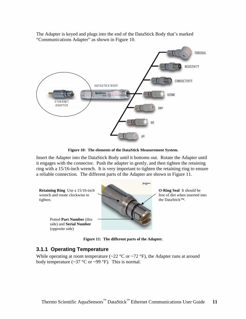
The Adapter is keyed and plugs into the end of the DataStick Body that’s marked “Communications Adapter” as shown in Figure 10.
Figure 10: The elements of the DataStick Measurement System.
Insert the Adapter into the DataStick Body until it bottoms out. Rotate the Adapter until it engages with the connector. Push the adapter in gently, and then tighten the retaining ring with a 15/16-inch wrench. It is very important to tighten the retaining ring to ensure a reliable connection. The different parts of the Adapter are shown in Figure 11.
Figure 11: The different parts of the Adapter.
3.1.1 Operating Temperature While operating at room temperature (~22 °C or ~72 °F), the Adapter runs at around body temperature (~37 °C or ~99 °F). This is normal.
ETHERNET ADAPTER
DATASTICK BODY
Potted Part Number (this side) and Serial Number (opposite side)
Retaining Ring Use a 15/16-inch wrench and rotate clockwise to tighten.
O-Ring Seal It should be free of dirt when inserted into the DataStick™.
Thermo Scientific AquaSensors™ DataStick™ Ethernet Communications User Guide 12
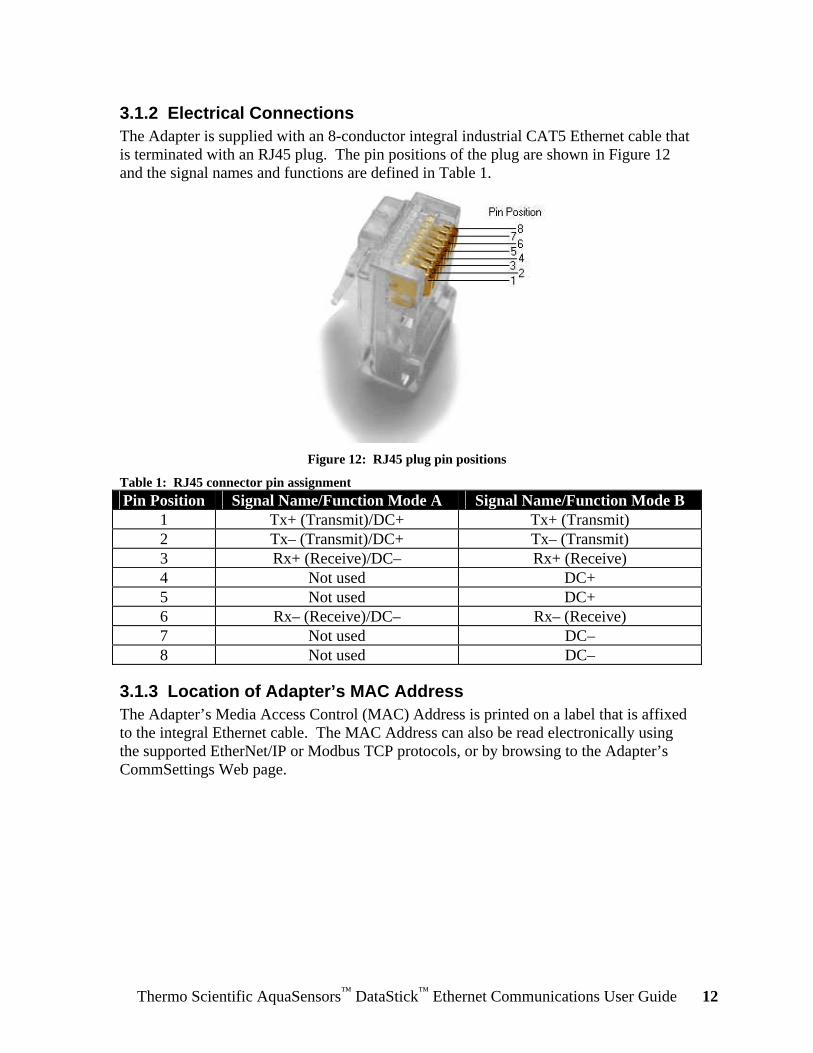
3.1.2 Electrical Connections The Adapter is supplied with an 8-conductor integral industrial CAT5 Ethernet cable that is terminated with an RJ45 plug. The pin positions of the plug are shown in Figure 12 and the signal names and functions are defined in Table 1.
Figure 12: RJ45 plug pin positions
Table 1: RJ45 connector pin assignment Pin Position Signal Name/Function Mode A Signal Name/Function Mode B
1 Tx+ (Transmit)/DC+ Tx+ (Transmit) 2 Tx– (Transmit)/DC+ Tx– (Transmit) 3 Rx+ (Receive)/DC– Rx+ (Receive) 4 Not used DC+ 5 Not used DC+ 6 Rx– (Receive)/DC– Rx– (Receive) 7 Not used DC– 8 Not used DC–
3.1.3 Location of Adapter’s MAC Address The Adapter’s Media Access Control (MAC) Address is printed on a label that is affixed to the integral Ethernet cable. The MAC Address can also be read electronically using the supported EtherNet/IP or Modbus TCP protocols, or by browsing to the Adapter’s CommSettings Web page.

Thermo Scientific AquaSensors™ DataStick™ Ethernet Communications User Guide 13
3.1.4 LED Indicators There are two bi-color LED indicators visible from the DataStick-end of the Adapter as shown in Figure 13.
Figure 13: LED indicators on the Adapter. Note that the Heartbeat LED is recessed while the
Link/Activity LED is not.
The Link/Activity LED glows green when there is a link between the Adapter and another network device, and it glows red when there is network activity.
The Heartbeat LED is recessed within the body of the Adapter. It blinks green at a rate of 1 Hz while the Adapter is operating normally. It blinks red and green to indicate that the IP Address, Subnet Mask, and Gateway Address have been restored to default values. See Section 3.1.5 for more information about restoring the communications settings to default values.
Link/Activity LED
Heartbeat LED (recessed)

Thermo Scientific AquaSensors™ DataStick™ Ethernet Communications User Guide 14
3.1.5 Restoring Default IP Address, Subnet Mask, Gateway Address In the event that the IP address of an Adapter is unknown, its communications settings can be restored to factory default values by following the procedure below:
Figure 14: Pin numbering and LED locations.
1. Disconnect the Adapter from the network. Attention: Determine how your control system will respond before disconnecting an Adapter from the network.
2. Detach the Adapter from the DataStick.
3. Make an electrical connection between pins 5 and 9 on the DataStick-side of the Adapter using a clip lead or equivalent as shown in Figure 14. Be careful to make the connection only between pins 5 and 9.
4. Apply power to the Adapter and watch the Heartbeat LED shown in Figure 14. After approximately 5 seconds, the Heartbeat LED will blink red and green at a rate of 2 Hz. This indicates that the Adapter has detected the connection between pins 5 and 9 and restored the communications settings to their factory default values.
5. Disconnect the power from the Adapter and remove the electrical connection between pins 5 and 9. Re-attach the Adapter to the DataStick.
6. Establish communications with the Adapter as described in Section 4.
Pin 1
Pin 2
Pin 5 Pin 9
Link/Activity LED
Heartbeat LED (recessed)

Thermo Scientific AquaSensors™ DataStick™ Ethernet Communications User Guide 15
3.2 AV38 Local Display with Ethernet Option
3.2.1 Electrical Connections The option is supplied with an 8-conductor integral RJ45 jack as shown in Figure 15. The signal names and functions of the jack are defined in Table 2. Table 2: RJ45 jack signal names and functions
Position Signal Name/Function Mode A Signal Name/Function Mode B 1 Tx+ (Transmit)/DC+ Tx+ (Transmit) 2 Tx– (Transmit)/DC+ Tx– (Transmit) 3 Rx+ (Receive)/DC– Rx+ (Receive) 4 Not used DC+ 5 Not used DC+ 6 Rx– (Receive)/DC– Rx– (Receive) 7 Not used DC– 8 Not used DC–
3.2.2 Location of AV38’s MAC Address The AV38’s Media Access Control (MAC) Address is printed on a label that is affixed to the terminal block overlay inside the AV38 as shown in Figure 15.
Figure 15: The AV38's MAC address is in the lower right-hand corner of the overlay.
Thermo Scientific AquaSensors™ DataStick™ Ethernet Communications User Guide 16
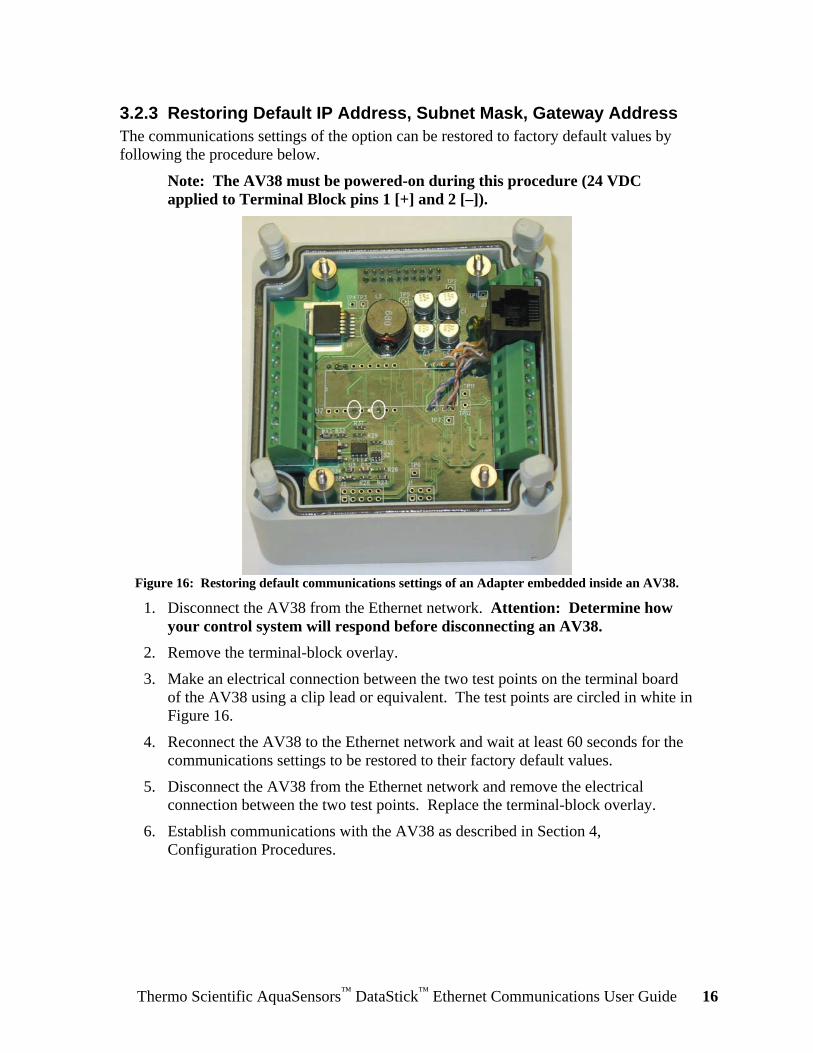
3.2.3 Restoring Default IP Address, Subnet Mask, Gateway Address The communications settings of the option can be restored to factory default values by following the procedure below.
Note: The AV38 must be powered-on during this procedure (24 VDC applied to Terminal Block pins 1 [+] and 2 [–]).
Figure 16: Restoring default communications settings of an Adapter embedded inside an AV38.
1. Disconnect the AV38 from the Ethernet network. Attention: Determine how your control system will respond before disconnecting an AV38.
2. Remove the terminal-block overlay.
3. Make an electrical connection between the two test points on the terminal board of the AV38 using a clip lead or equivalent. The test points are circled in white in Figure 16.
4. Reconnect the AV38 to the Ethernet network and wait at least 60 seconds for the communications settings to be restored to their factory default values.
5. Disconnect the AV38 from the Ethernet network and remove the electrical connection between the two test points. Replace the terminal-block overlay.
6. Establish communications with the AV38 as described in Section 4, Configuration Procedures.
Thermo Scientific AquaSensors™ DataStick™ Ethernet Communications User Guide 17
4 Configuration Procedures The product is shipped from Thermo Fisher Scientific with a static IP address, subnet mask and default gateway that can be changed by the user to conform to specific networking requirements. These changes can be made from the resident Web page.
The product stores communications settings and other information in its own non-volatile memory. You must, therefore, access the product to view and edit these parameters.
Changes to the IP Address, Subnet Mask, and Gateway Address require that you reset the product before the new settings take effect. You can reset the product by cycling its power.
Please contact Thermo Fisher Scientific for a list of networking infrastructure hardware that includes manufacturers of power injectors as well as 802.3af-compliant industrial and home/office Ethernet switches.
Note: When the Ethernet product’s cable is moved from one port on an Ethernet switch to another, communication with that product will not be possible until the tables inside the switch are rebuilt by cycling the switch’s power.
Optionally, a virtual private network (VPN) can be established between Thermo Fisher Scientific and the customer’s site to allow Thermo Fisher Scientific to configure and diagnose Ethernet communications products and upgrade them if necessary.
The default static IP address for Thermo Scientific AquaSensors Ethernet products is provided on a paper tag for initial access and setup. When connecting to a network, be sure to configure an IP address that will not be in conflict with other devices or DHCP servers on the network. If there is an IP address conflict, several devices on the network may not communicate.
Note: It is important to tag Thermo Scientific AquaSensors Ethernet communications products with currently configured IP address information so that they can always be accessed.
Thermo Fisher Scientific ships Ethernet communications products with a paper tag that gives currently configured IP address information along with a permanent tag that gives the MAC address. For customers that order a preconfigured IP address, a permanent IP address label can be provided.
In the event that the IP address for a Thermo Scientific AquaSensors Ethernet product is lost, there are two ways to regain communications. The first involves a Discovery Utility provided by Thermo Fisher Scientific that will find all Thermo Scientific AquaSensors Ethernet communications products on a network and allow their IP addresses, subnet masks and default gateways to be changed. The second involves restoring the settings to default values as described in Section 3.
Configuration procedures in this section are explained using the Windows xp operating system. When other operating systems are used, procedures may be slightly different.
When possible, obtain an IP address, subnet mask and default gateway from a network administrator.

Thermo Scientific AquaSensors™ DataStick™ Ethernet Communications User Guide 18
There are many situations that may necessitate changing the configuration of the product. This section describes two: The first involves evaluating or demonstrating an Ethernet DataStick and the second involves configuring a product that’s to be put into service.
There are many ways to connect a product to a computer so that it can be configured. This section describes three:
1. Using a power injector and a CAT5 cross-over cable
2. Using an Ethernet hub or switch and a CAT5 patch cable
3. Using an 802.3af-compliant (PoE) Ethernet hub or switch and a CAT5 patch cable
Choose the way that is most convenient for you.
Attention: Determine how your control system will respond before disconnecting a product from the network.
Thermo Scientific AquaSensors™ DataStick™ Ethernet Communications User Guide 19
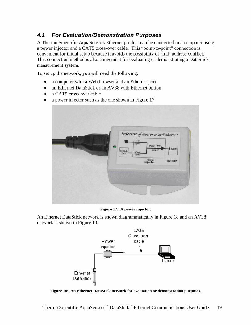
4.1 For Evaluation/Demonstration Purposes A Thermo Scientific AquaSensors Ethernet product can be connected to a computer using a power injector and a CAT5 cross-over cable. This “point-to-point” connection is convenient for initial setup because it avoids the possibility of an IP address conflict. This connection method is also convenient for evaluating or demonstrating a DataStick measurement system.
To set up the network, you will need the following:
• a computer with a Web browser and an Ethernet port • an Ethernet DataStick or an AV38 with Ethernet option • a CAT5 cross-over cable • a power injector such as the one shown in Figure 17
Figure 17: A power injector.
An Ethernet DataStick network is shown diagrammatically in Figure 18 and an AV38 network is shown in Figure 19.
Figure 18: An Ethernet DataStick network for evaluation or demonstration purposes.

Thermo Scientific AquaSensors™ DataStick™ Ethernet Communications User Guide 20
Figure 19: An AV38 network for evaluation or demonstration purposes.
The first step is to restore the product’s communications settings to default values. This will guarantee that the product’s IP address is known. Follow the appropriate procedure in Section 3 to accomplish this. If you’re sure that the communications settings haven’t been changed since the product was received from Thermo Fisher Scientific, then this step can be skipped.
The next step is to change the IP address of the laptop to 192.168.0.1 so that it can communicate with the product. Follow the procedure below to accomplish this.
Attention: If the laptop is connected to a network, disconnect the laptop before continuing. This will avoid any potential conflicts during the configuration procedure.
Go to the Network Connections window shown in Figure 20 by clicking Start | Control Panel | Network Connections.
Figure 20: Network Connections window.
Thermo Scientific AquaSensors™ DataStick™ Ethernet Communications User Guide 21
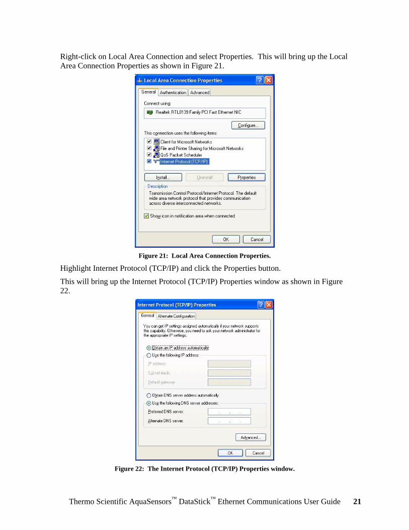
Right-click on Local Area Connection and select Properties. This will bring up the Local Area Connection Properties as shown in Figure 21.
Figure 21: Local Area Connection Properties.
Highlight Internet Protocol (TCP/IP) and click the Properties button.
This will bring up the Internet Protocol (TCP/IP) Properties window as shown in Figure 22.
Figure 22: The Internet Protocol (TCP/IP) Properties window.
Thermo Scientific AquaSensors™ DataStick™ Ethernet Communications User Guide 22
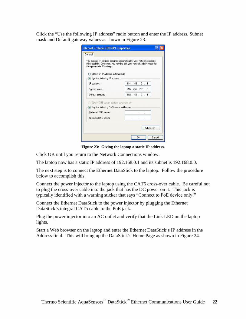
Click the “Use the following IP address” radio button and enter the IP address, Subnet mask and Default gateway values as shown in Figure 23.
Figure 23: Giving the laptop a static IP address.
Click OK until you return to the Network Connections window.
The laptop now has a static IP address of 192.168.0.1 and its subnet is 192.168.0.0.
The next step is to connect the Ethernet DataStick to the laptop. Follow the procedure below to accomplish this.
Connect the power injector to the laptop using the CAT5 cross-over cable. Be careful not to plug the cross-over cable into the jack that has the DC power on it. This jack is typically identified with a warning sticker that says “Connect to PoE device only!”
Connect the Ethernet DataStick to the power injector by plugging the Ethernet DataStick’s integral CAT5 cable to the PoE jack.
Plug the power injector into an AC outlet and verify that the Link LED on the laptop lights.
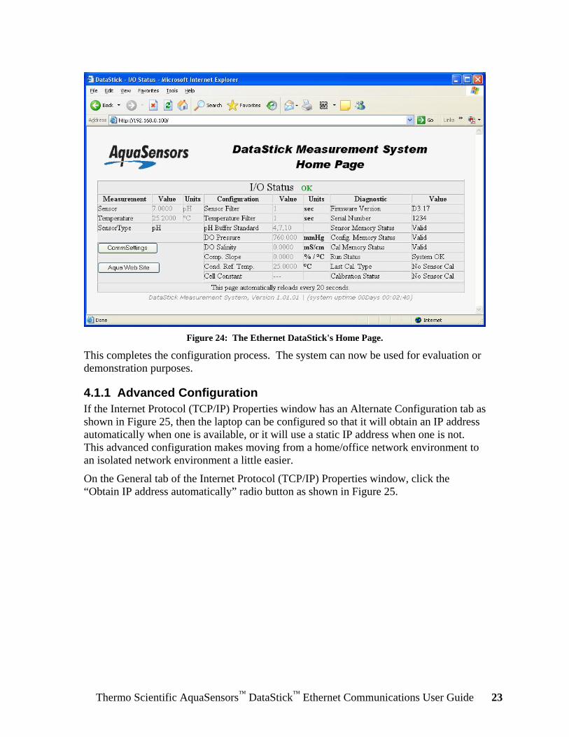
Start a Web browser on the laptop and enter the Ethernet DataStick’s IP address in the Address field. This will bring up the DataStick’s Home Page as shown in Figure 24.
Thermo Scientific AquaSensors™ DataStick™ Ethernet Communications User Guide 23
Figure 24: The Ethernet DataStick's Home Page.
This completes the configuration process. The system can now be used for evaluation or demonstration purposes.
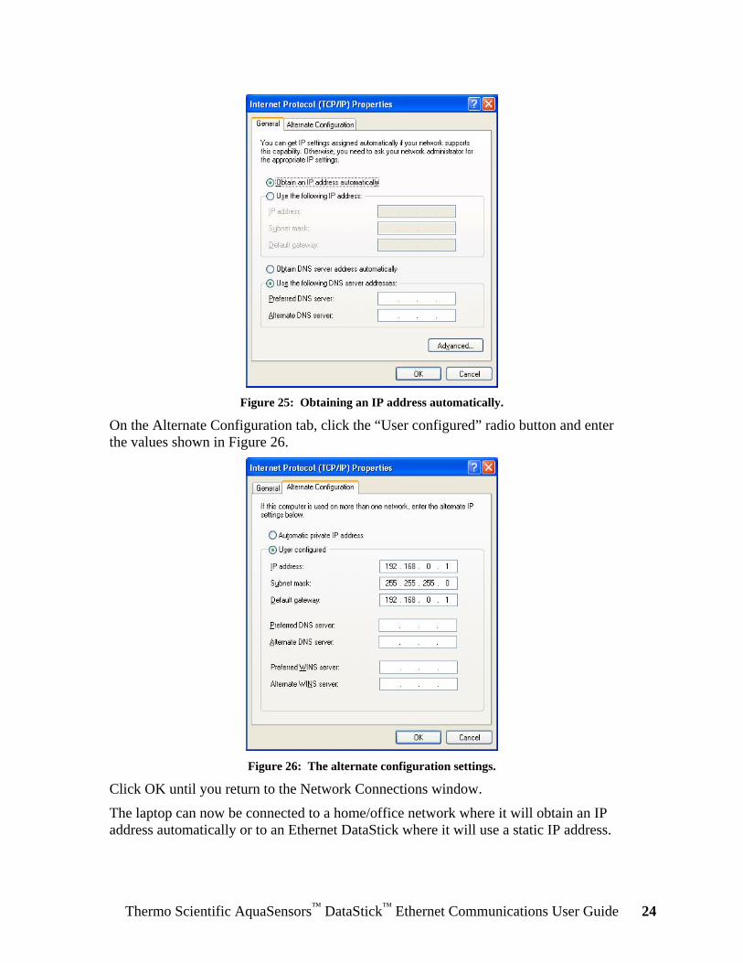
4.1.1 Advanced Configuration If the Internet Protocol (TCP/IP) Properties window has an Alternate Configuration tab as shown in Figure 25, then the laptop can be configured so that it will obtain an IP address automatically when one is available, or it will use a static IP address when one is not. This advanced configuration makes moving from a home/office network environment to an isolated network environment a little easier.
On the General tab of the Internet Protocol (TCP/IP) Properties window, click the “Obtain IP address automatically” radio button as shown in Figure 25.
Thermo Scientific AquaSensors™ DataStick™ Ethernet Communications User Guide 24
Figure 25: Obtaining an IP address automatically.
On the Alternate Configuration tab, click the “User configured” radio button and enter the values shown in Figure 26.
Figure 26: The alternate configuration settings.
Click OK until you return to the Network Connections window.
The laptop can now be connected to a home/office network where it will obtain an IP address automatically or to an Ethernet DataStick where it will use a static IP address.

Thermo Scientific AquaSensors™ DataStick™ Ethernet Communications User Guide 25
4.2 Commissioning an Ethernet Product for Service This section describes how to configure an Ethernet product so that it can be connected to an existing network.
First, the network’s subnet must be determined.
Note: If a network administrator has provided you with an IP address, subnet mask and default gateway, then this step can be skipped.
This can be done using the ipconfig command in a Command Prompt on a Windows xp computer that’s connected to the destination network as shown in Figure 27. To open a Command Prompt, click Start | Run, and type cmd in the Open field.
Figure 27: The output of the ipconfig command.
To determine the network’s subnet, bitwise-AND the IP address with the subnet mask. In the example of Figure 27, the IP address is 192.168.10.107 and the subnet mask is 255.255.255.0:
192.168.10.107 bitwise-ANDed with 255.255.255.0 yields 192.168.10.0—this is the network’s subnet. It means that the Ethernet DataStick to be added must be given an IP address between 192.168.10.1 and 192.168.10.254 in order to be accessible by other devices on the network.
192.168.010.107 AND 255.255.255.000 192.168.010.000
Thermo Scientific AquaSensors™ DataStick™ Ethernet Communications User Guide 26
Next, the product’s communications settings must be restored to default values. This will guarantee that its IP address is known. Follow the procedure described in Section 3 to accomplish this. If you’re sure that the communications settings haven’t been changed since the product was received from Thermo Fisher Scientific, then this step can be skipped.
Next, an isolated network must be set up consisting of a computer and an Ethernet DataStick, and the IP address of the computer must be changed so it can communicate with the DataStick. Follow the procedure below to accomplish this. Windows xp is used, but Windows 2000 and Vista, as well as other operating systems, will also work.
An isolated network can be constructed in several different ways depending upon the equipment that’s available.
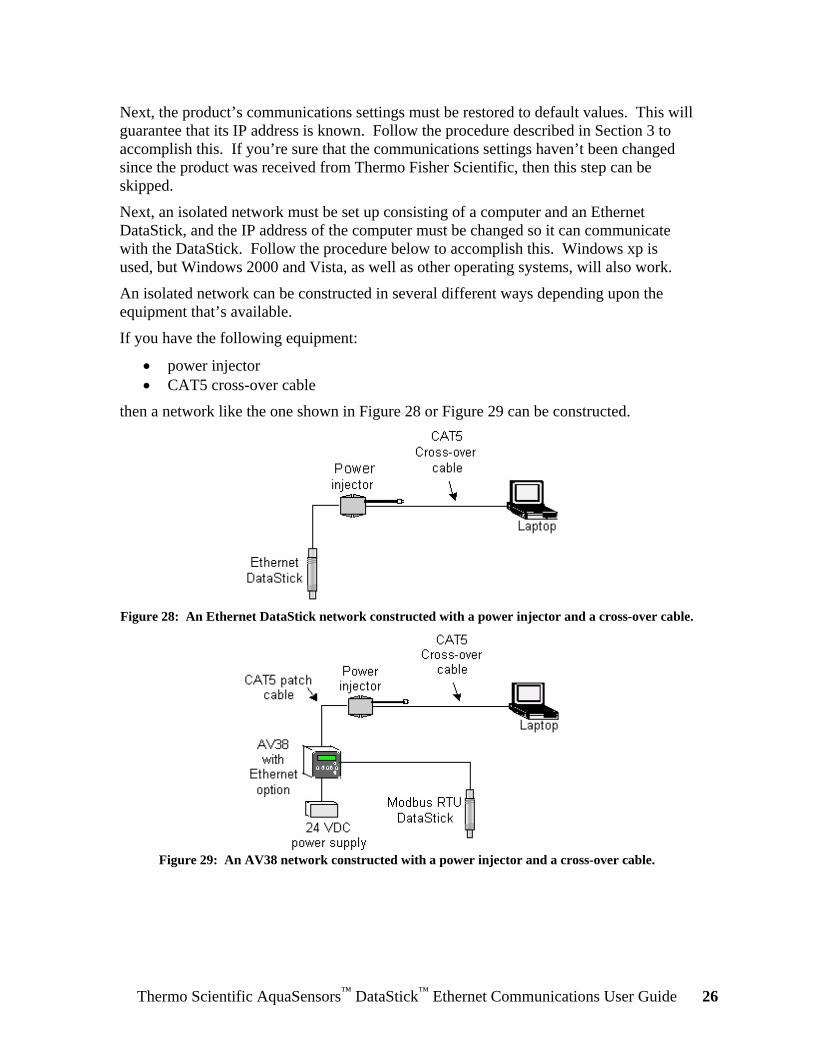
If you have the following equipment:
• power injector • CAT5 cross-over cable
then a network like the one shown in Figure 28 or Figure 29 can be constructed.
Figure 28: An Ethernet DataStick network constructed with a power injector and a cross-over cable.
Figure 29: An AV38 network constructed with a power injector and a cross-over cable.

Thermo Scientific AquaSensors™ DataStick™ Ethernet Communications User Guide 27
If you have the following equipment:
• Ethernet hub or switch • CAT5 patch cable
then a network like the one shown in Figure 30 or Figure 31 can be constructed.
Figure 30: An Ethernet DataStick network constructed with an Ethernet switch and patch cables.
Figure 31: An AV38 network constructed with an Ethernet switch and patch cables.
Thermo Scientific AquaSensors™ DataStick™ Ethernet Communications User Guide 28
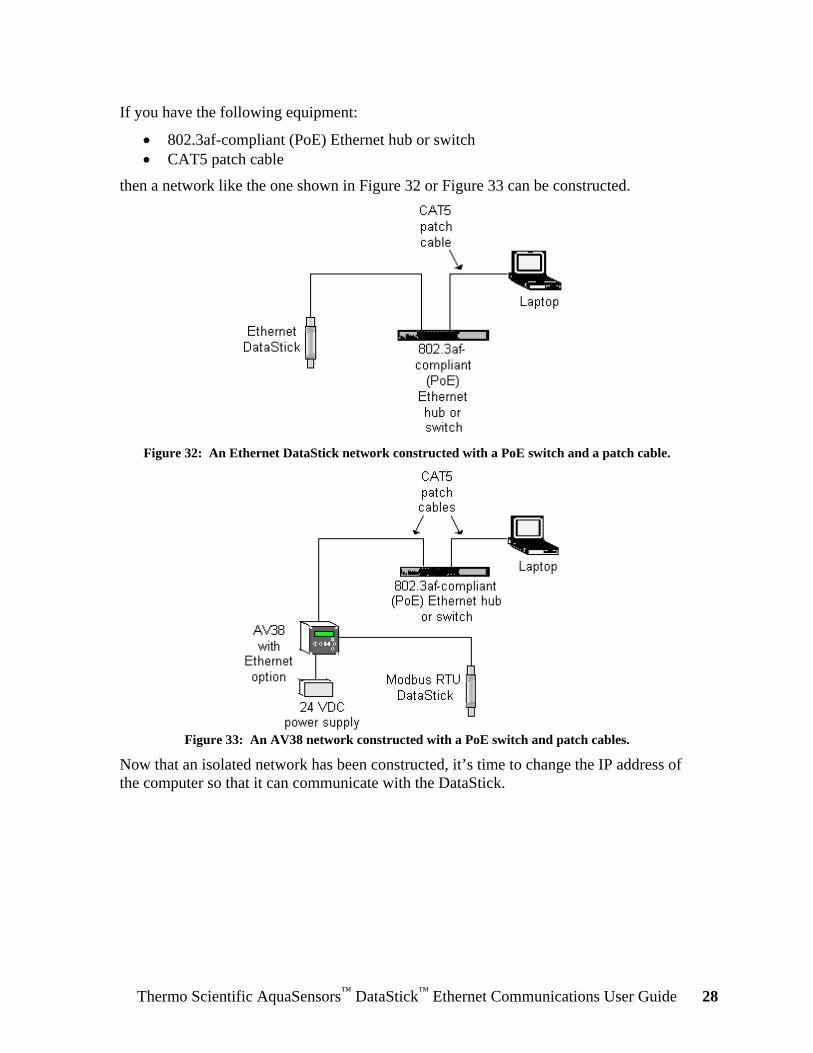
If you have the following equipment:
• 802.3af-compliant (PoE) Ethernet hub or switch • CAT5 patch cable
then a network like the one shown in Figure 32 or Figure 33 can be constructed.
Figure 32: An Ethernet DataStick network constructed with a PoE switch and a patch cable.
Figure 33: An AV38 network constructed with a PoE switch and patch cables.
Now that an isolated network has been constructed, it’s time to change the IP address of the computer so that it can communicate with the DataStick.
Thermo Scientific AquaSensors™ DataStick™ Ethernet Communications User Guide 29
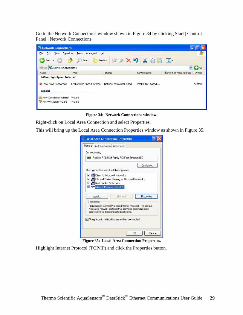
Go to the Network Connections window shown in Figure 34 by clicking Start | Control Panel | Network Connections.
Figure 34: Network Connections window.
Right-click on Local Area Connection and select Properties.
This will bring up the Local Area Connection Properties window as shown in Figure 35.
Figure 35: Local Area Connection Properties.
Highlight Internet Protocol (TCP/IP) and click the Properties button.
Thermo Scientific AquaSensors™ DataStick™ Ethernet Communications User Guide 30
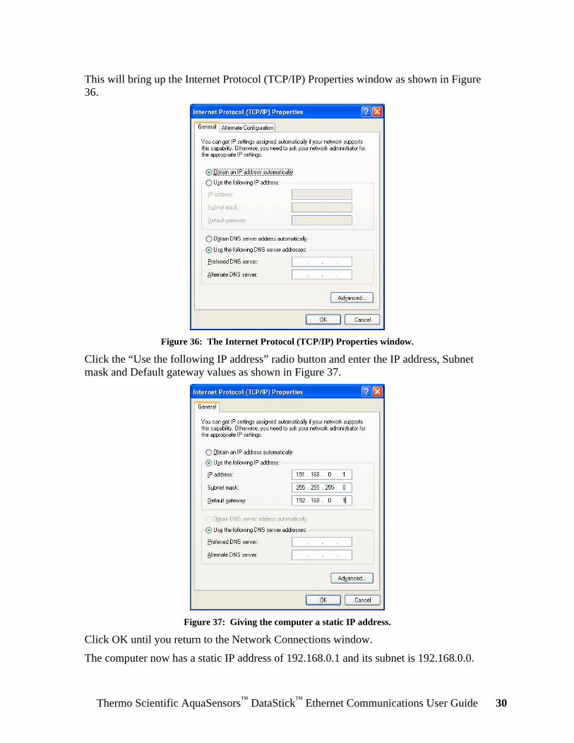
This will bring up the Internet Protocol (TCP/IP) Properties window as shown in Figure 36.
Figure 36: The Internet Protocol (TCP/IP) Properties window.
Click the “Use the following IP address” radio button and enter the IP address, Subnet mask and Default gateway values as shown in Figure 37.
Figure 37: Giving the computer a static IP address.
Click OK until you return to the Network Connections window.
The computer now has a static IP address of 192.168.0.1 and its subnet is 192.168.0.0.

Thermo Scientific AquaSensors™ DataStick™ Ethernet Communications User Guide 31
The next step is to change the IP address of the Ethernet DataStick. Follow the procedure below to accomplish this.
When an Ethernet DataStick is connected to a network with a DHCP server we recommend that the candidate address be chosen so that it’s below the range of IP addresses controlled by the DHCP server. This will avoid potential conflicts between the Ethernet DataStick and any devices that might be added to the network at a later time. Before settling on the candidate address for the Ethernet DataStick, use the ping utility to verify that there is not already a device at that address. Figure 38 shows the output of the ping command that was run on a computer connected to the network to which the Ethernet DataStick will be connected.
Figure 38: Verifying that no device is present using the ping command.

Thermo Scientific AquaSensors™ DataStick™ Ethernet Communications User Guide 32
Start a Web browser on the computer and enter 192.168.0.100 in the Address field. This will bring up the DataStick’s Home Page as shown in Figure 39.
Figure 39: The Ethernet DataStick's Home Page.
Thermo Scientific AquaSensors™ DataStick™ Ethernet Communications User Guide 33
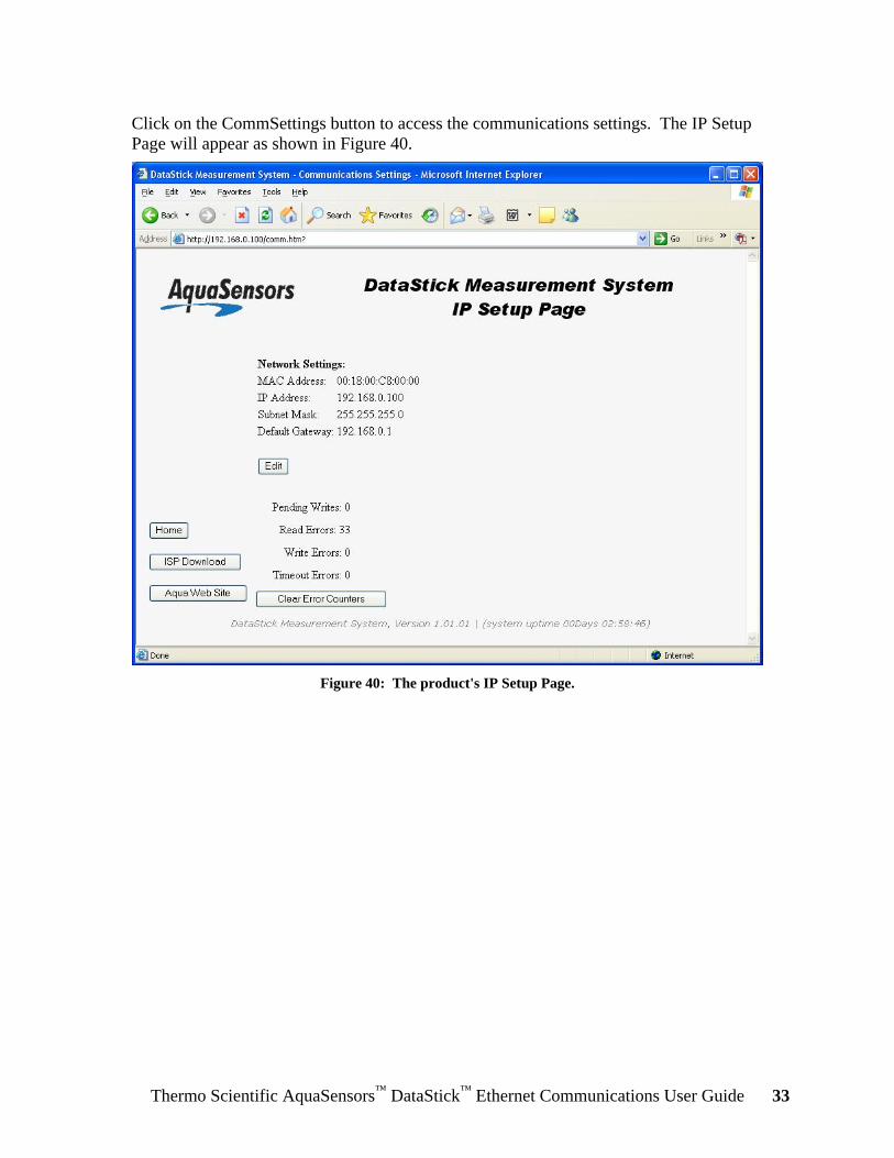
Click on the CommSettings button to access the communications settings. The IP Setup Page will appear as shown in Figure 40.
Figure 40: The product's IP Setup Page.

Thermo Scientific AquaSensors™ DataStick™ Ethernet Communications User Guide 34
Click the Edit button and enter the following information:
• User name: aqa • Password: aqa
as shown in Figure 41.
Figure 41: Entering the username and password in the IP Setup Page.

Thermo Scientific AquaSensors™ DataStick™ Ethernet Communications User Guide 35
Edit the IP Address, Subnet Mask and Gateway Address as desired. For this example, the desired IP address is 192.168.10.200 as shown in Figure 42.
Figure 42: The IP address, subnet mask and gateway address edited as desired.
After the values have been edited as desired, click the Apply button.
To abort this step, click the Cancel button. The IP Address, Subnet Mask and Default Gateway will be returned to their previous values.

Thermo Scientific AquaSensors™ DataStick™ Ethernet Communications User Guide 36
Now the power to the product must be cycled so that the new communications settings will take effect. Cycle the power by disconnecting and reconnecting the product’s Ethernet connection.
Enter the product’s new IP address in the Address field of the Web browser to bring up the Home Page as shown in Figure 43.
Figure 43: The Home Page as seen from the Product's new IP address.
The Ethernet DataStick’s communications settings have now been set as desired and it can be connected to the desired network.
This completes the configuration procedure.
Thermo Scientific AquaSensors™ DataStick™ Ethernet Communications User Guide 37
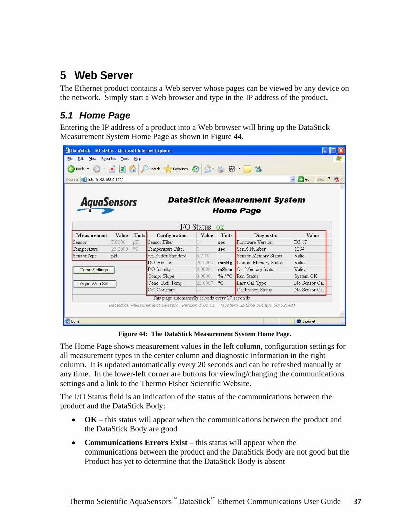
5 Web Server The Ethernet product contains a Web server whose pages can be viewed by any device on the network. Simply start a Web browser and type in the IP address of the product.
5.1 Home Page Entering the IP address of a product into a Web browser will bring up the DataStick Measurement System Home Page as shown in Figure 44.
Figure 44: The DataStick Measurement System Home Page.
The Home Page shows measurement values in the left column, configuration settings for all measurement types in the center column and diagnostic information in the right column. It is updated automatically every 20 seconds and can be refreshed manually at any time. In the lower-left corner are buttons for viewing/changing the communications settings and a link to the Thermo Fisher Scientific Website.
The I/O Status field is an indication of the status of the communications between the product and the DataStick Body:
• OK – this status will appear when the communications between the product and the DataStick Body are good
• Communications Errors Exist – this status will appear when the communications between the product and the DataStick Body are not good but the Product has yet to determine that the DataStick Body is absent
Thermo Scientific AquaSensors™ DataStick™ Ethernet Communications User Guide 38
• No DataStick Communications – this status will appear when the product has been detached from the DataStick Body
If the Sensor Head is removed from the DataStick Body, then the Sensor Type field will indicate “No Sensor”.
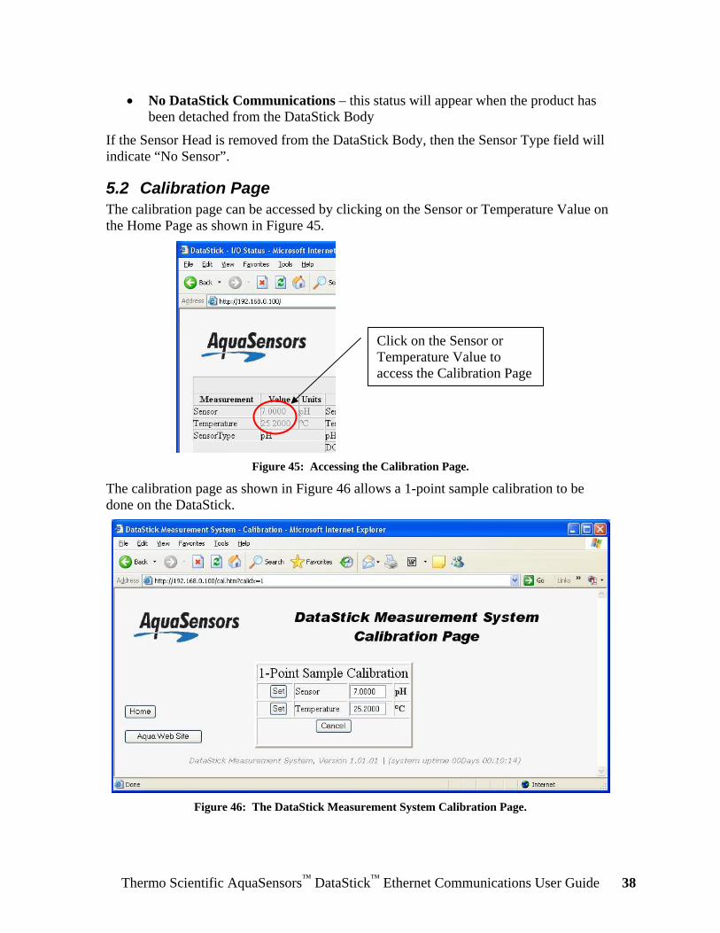
5.2 Calibration Page The calibration page can be accessed by clicking on the Sensor or Temperature Value on the Home Page as shown in Figure 45.
Figure 45: Accessing the Calibration Page.
The calibration page as shown in Figure 46 allows a 1-point sample calibration to be done on the DataStick.
Figure 46: The DataStick Measurement System Calibration Page.
Click on the Sensor or Temperature Value to access the Calibration Page

Thermo Scientific AquaSensors™ DataStick™ Ethernet Communications User Guide 39
To perform a 1-point sample calibration on the Sensor or the Temperature measurement, enter the desired value in the Sensor or Temperature field and click the corresponding Set button. The calibration procedure can be monitored by returning to the Home Page and observing the Sensor or Temperature Value, and the Last Cal Type and Calibration Status fields. Calibration Status will indicate Cal OK if the procedure completed successfully.
Clicking the Cancel button instead of the Set button will return the 1-Point Sample Calibration value to its previous value.
5.3 Configuration Page The configuration edit page can be accessed by clicking on any of the Measurement Units or Configuration Values on the Home Page as shown in Figure 47.
Figure 47: Accessing the Configuration Edit Page.
Click on any of the Measurement Units or Configuration Values to access the Configuration Edit Page
Thermo Scientific AquaSensors™ DataStick™ Ethernet Communications User Guide 40
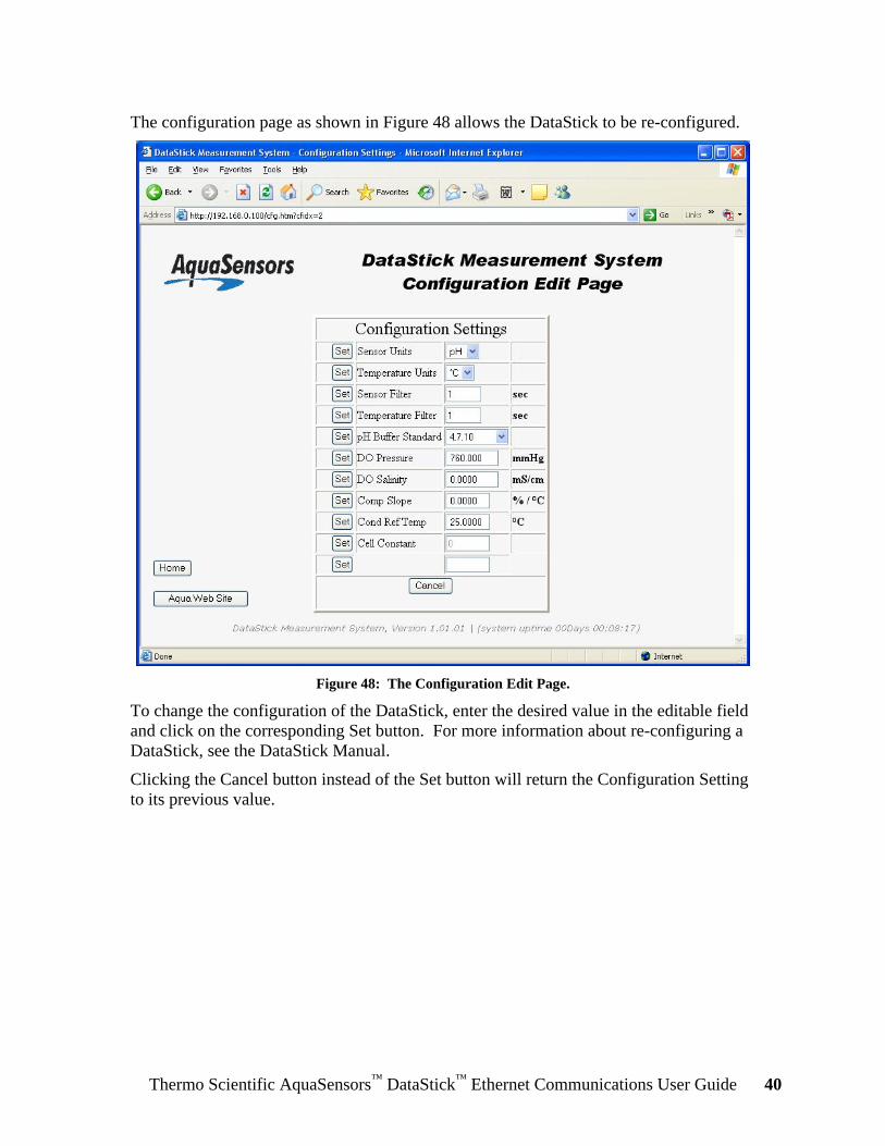
The configuration page as shown in Figure 48 allows the DataStick to be re-configured.
Figure 48: The Configuration Edit Page.
To change the configuration of the DataStick, enter the desired value in the editable field and click on the corresponding Set button. For more information about re-configuring a DataStick, see the DataStick Manual.
Clicking the Cancel button instead of the Set button will return the Configuration Setting to its previous value.
Thermo Scientific AquaSensors™ DataStick™ Ethernet Communications User Guide 41
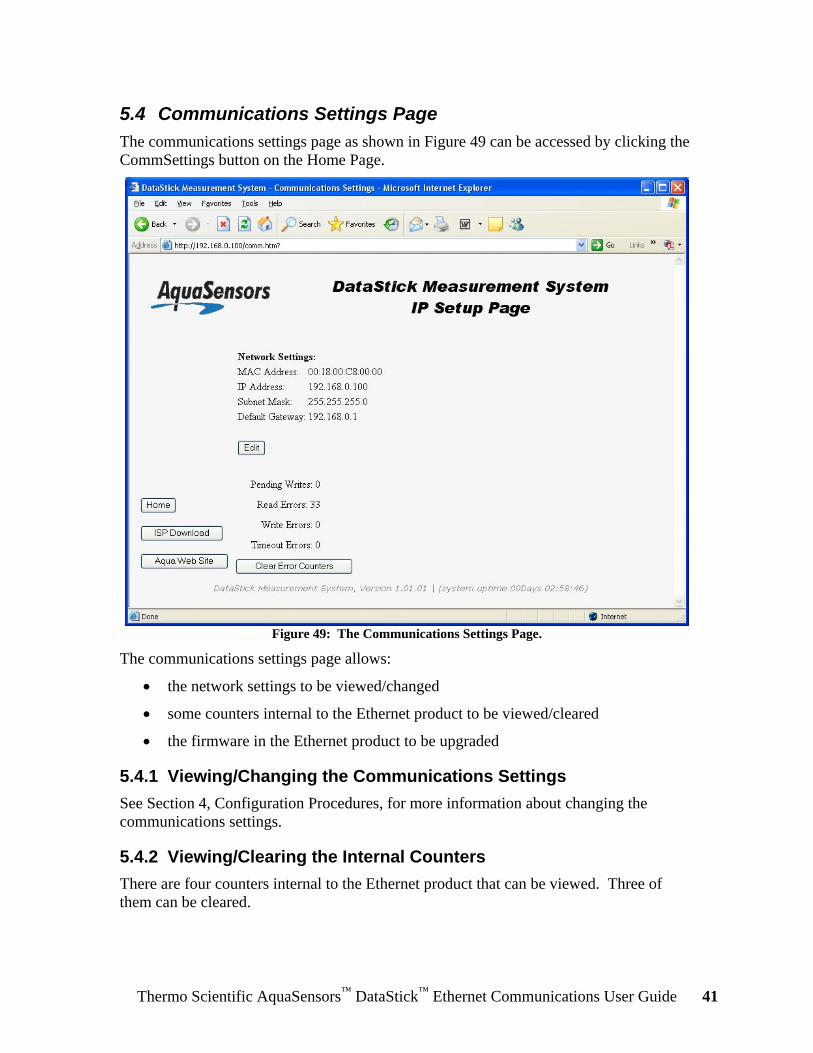
5.4 Communications Settings Page The communications settings page as shown in Figure 49 can be accessed by clicking the CommSettings button on the Home Page.
Figure 49: The Communications Settings Page.
The communications settings page allows:
• the network settings to be viewed/changed
• some counters internal to the Ethernet product to be viewed/cleared
• the firmware in the Ethernet product to be upgraded
5.4.1 Viewing/Changing the Communications Settings See Section 4, Configuration Procedures, for more information about changing the communications settings.
5.4.2 Viewing/Clearing the Internal Counters There are four counters internal to the Ethernet product that can be viewed. Three of them can be cleared.

Thermo Scientific AquaSensors™ DataStick™ Ethernet Communications User Guide 42
The Pending Writes counter is incremented every time the Ethernet product has been asked to write to the DataStick but has not yet completed the operation. The counter is decremented each time a write completes.
The Read Errors counter is incremented every time the Ethernet product receives an error while trying to read from the DataStick. It is a count of the total number of read errors for all of the protocols supported. Some configuration data might not be available depending on the type of Sensor Head installed in the DataStick Body. When the Ethernet product tries to read this unavailable data the DataStick will respond with an error and this will cause the Read Errors counter to be incremented. The Ethernet product will realize that this data is unavailable and stop requesting it.
The Write Errors counter is incremented every time the Ethernet product receives an error while trying to write to the DataStick. It is a count of the total number of write errors for all of the protocols supported. For instance, if an attempt is made to change the Sensor Filter value to 200 using the Web Server’s Configuration Page, the DataStick will respond with an error because the largest acceptable value is 100 and this will cause the Write Errors counter to be incremented.
The Timeout Errors counter is incremented every time the Ethernet product fails to receive a response from the DataStick in a reasonable amount of time. It is a count of the total number of write errors for all of the protocols supported.
The error counters can be cleared to 0 by clicking the Clear Error Counters button.
5.4.3 Upgrading the Firmware The firmware in the Ethernet product can be upgraded by clicking on the ISP Download button. Thermo Fisher Scientific will provide you with further instructions in the event that a firmware upgrade becomes necessary.
Thermo Scientific AquaSensors™ DataStick™ Ethernet Communications User Guide 43
6 EtherNet/IP The product supports all measure, calibrate, configure and diagnose features of the DataStick via EtherNet/IP.
EtherNet/IP™ is a low-cost open industrial network that links industrial devices (such as limit switches, photoelectric sensors and motor starters) to machine controllers over Ethernet.
This section describes the EtherNet/IP Network Object Model which completely describes the interface from the EtherNet/IP network point of view. It also describes the unit configuration, unit initialization and the EtherNet/IP Network Model.
6.1 Electronic Data Sheet (EDS) The EtherNet/IP Electronic Data Sheet (EDS) is called 282EEIP.eds and can be found on the Ethernet Files CD that is supplied with the Ethernet product. Be sure to register the EDS file with the configuration tool that you will be using.
6.2 Definitions Network Client The EtherNet/IP network host (commonly a scanner module
in a programmable logic controller)
Network Server An EtherNet/IP device that implements server functionality in an EtherNet/IP system
Programmable Logic Controller
PLC refers to the EtherNet/IP network host
BYTE An unsigned 8-bit value
USINT Unsigned Short Integer, see BYTE
UINT Unsigned Integer, a 16-bit unsigned value
WORD See UINT
BOOL A logical type (TRUE or FALSE) which may be represented by a single bit
REAL Floating point, specifically IEEE 32-bit single precision
UDINT Unsigned Double Integer, a 32-bit unsigned value
SHORT_STRING A string of bytes in which the first byte contains the length
NAN Not A Number, a specific value for IEEE floating-point to indicate NO-DATA
6.3 Reference Documents • ODVA Volume 1: CIP Common Specification, Edition 3.1 ©2006 ODVA • ODVA Volume 2: EtherNet/IP Adaptation of CIP, Edition 1.3 ©2006 ODVA

Thermo Scientific AquaSensors™ DataStick™ Ethernet Communications User Guide 44
6.4 Open DeviceNet Vendor Association, Inc. (ODVA) ODVA is an independent supplier organization that manages the EtherNet/IP specification and supports the worldwide growth of EtherNet/IP.
6.5 Object Model The product’s EtherNet/IP object model is fashioned after the object model for the Thermo Scientific AquaSensors DeviceNet Communications Product (CA-b-5R or AV38-W-X-5). As a result, the objects shown in Table 3 are identical. This reduces the impact of changing the communications protocol after the application has been created.
Table 3: These objects are identical in the Ethernet products and DeviceNet Adapter object models. Object Name System Status Sensor Installation Sensor Value User Configuration Generic Sensor Calibration Conductivity Sensor Calibration Mode Configuration
For a detailed explanation of the Instance Attributes, please see the description of the associated Thermo Scientific AquaSensors Command in the DataStick Measurement System Instruction Manual.
6.5.1 Configuration The product supports Thermo Scientific AquaSensors “factory” configuration parameters and user configuration parameters. All configuration data is stored in non-volatile memory.
6.5.2 Identity Object (01HEX – 1 Instance)
6.5.2.1 Class Attributes
Attribute ID Name EtherNet/IP Data Type
Data Value
Access Rule
1 Revision UINT 1 Get

Thermo Scientific AquaSensors™ DataStick™ Ethernet Communications User Guide 45
6.5.2.2 Instance Attributes
Attribute ID Name EtherNet/IP Data Type
Data Value Access Rule
1 Vendor Number UINT 995DEC Get 2 Device Type UINT 0 Get 3 Product Code Number UINT 11605DEC Get 4 Product Major Revision
Product Minor Revision USINT USINT
01 01
Get
5 Status WORD See Below Get 6 Serial Number UDINT Unique
32 Bit Value Get
7 Product Name SHORT_STRING DataStick Get
6.5.2.3 Status Word
Bit Bit = 0 Bit = 1 0 Not Owned Owned (I/O Connection Allocated)
1 – 7 Unused Unused 8 Serial Comms OK Serial Timeout
9 – 15 Unused Unused
6.5.2.4 Common Services
Implemented for Service Code Class Level Instance Level
Service Name
0EHEX Yes Yes Get_Attribute_Single 05HEX No Yes Reset
6.5.3 Message Router Object (02HEX – 0 Instances) No attributes or services supported.
6.5.4 Assembly Object (04HEX – 2 Instances)
6.5.4.1 Class Attributes
Attribute ID Name EtherNet/IP Data Type Data Value Access Rule 1 Revision UINT 2 Get 2 Max Instance UINT 130 Get
6.5.4.2 Instance 100 (64 hex) Attributes (Input Instance)
Attribute ID Name EtherNet/IP Data Type
Default Data Value
Access Rule
3 Input Data - Sensor Value - Sensor Temperature
REAL[2] NAN Get
6.5.4.3 Output Instance 128 – (Heartbeat Instance – Input Only) This instance allows clients to monitor input data without providing output data.
6.5.4.4 Output Instance 129 – (Heartbeat Instance – Listen Only) This instance allows clients to monitor input data without providing output data. To utilize this connection type, an owning connection must exist from a second Client and the configuration of the connection must match exactly.
Thermo Scientific AquaSensors™ DataStick™ Ethernet Communications User Guide 46
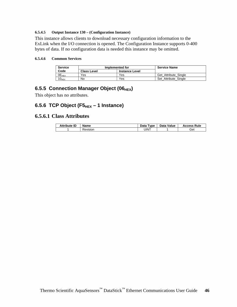
6.5.4.5 Output Instance 130 – (Configuration Instance) This instance allows clients to download necessary configuration information to the ExLink when the I/O connection is opened. The Configuration Instance supports 0-400 bytes of data. If no configuration data is needed this instance may be omitted.
6.5.4.6 Common Services
Implemented for Service Code Class Level Instance Level
Service Name
0EHEX Yes Yes Get_Attribute_Single 10HEX No Yes Set_Attribute_Single
6.5.5 Connection Manager Object (06HEX) This object has no attributes.
6.5.6 TCP Object (F5HEX – 1 Instance)
6.5.6.1 Class Attributes
Attribute ID Name Data Type Data Value Access Rule 1 Revision UINT 1 Get

Thermo Scientific AquaSensors™ DataStick™ Ethernet Communications User Guide 47
6.5.6.2 Instance Attributes
Attribute ID Name Data Type Default Data Value
Access Rule
1 Status1 DWORD 1 Get 2 Configuration Capability2 DWORD 0 Get 3 Configuration Control3 DWORD 0 Get 4 Physical Link Object4
Structure of: Path Size Path
UINT Array Of WORD
2 0x20F6 0x2401
Get
5 Interface Configuration5 Structure of: IP Address Network Mask Gateway Address Name Server Name Server 2 Domain Name Size Domain Name
UDINT UDINT UDINT UDINT UDINT UINT
STRING
0 0 0 0 0 0 0
Get
6 Host Name6 Structure of: Host Name Size Host Name
UINT STRING
0 0
Get
6.5.6.3 Common Services
Implemented for Service Code Class Level Instance Level
Service Name
0EHEX Yes Yes Get_Attribute_Single 10HEX No Yes Set_Attribute_Single
6.5.7 Ethernet Link Object (F6HEX – 1 Instance)
6.5.7.1 Class Attributes
Attribute ID Name Data Type Data Value Access Rule 1 Revision UINT 1 Get
6.5.7.2 Instance Attributes
Attribute ID Name Data Type Default Data Value
Access Rule
1 Interface Speed7 UDINT 10 Get 2 Interface Flags8 DWORD 3 Get 3 Physical Address9 USINT Array[6] 0 Get
1 See section 5-3.2.2.1 of “Volume 2: EtherNet/IP Adaptation of CIP” from ODVA for more details on this attribute. 2 See section 5-3.2.2.2 of “Volume 2: EtherNet/IP Adaptation of CIP” from ODVA for more details on this attribute. 3 See section 5-3.2.2.3 of “Volume 2: EtherNet/IP Adaptation of CIP” from ODVA for more details on this attribute. 4 See section 5-3.2.2.4 of “Volume 2: EtherNet/IP Adaptation of CIP” from ODVA for more details on this attribute. 5 See section 5-3.2.2.5 of “Volume 2: EtherNet/IP Adaptation of CIP” from ODVA for more details on this attribute. 6 See section 5-3.2.2.6 of “Volume 2: EtherNet/IP Adaptation of CIP” from ODVA for more details on this attribute. 7 See section 5-4.2.2.1 of “Volume 2: EtherNet/IP Adaptation of CIP” from ODVA for more details on this attribute. 8 See section 5-4.2.2.2 of “Volume 2: EtherNet/IP Adaptation of CIP” from ODVA for more details on this attribute. 9 See section 5-4.2.2.3 of “Volume 2: EtherNet/IP Adaptation of CIP” from ODVA for more details on this attribute.

Thermo Scientific AquaSensors™ DataStick™ Ethernet Communications User Guide 48
6.5.7.3 Common Services
Implemented for Service Code Class Level Instance Level
Service Name
0EHEX Yes Yes Get_Attribute_Single
6.5.8 System Status Object (64HEX – 1 Instance) When power is applied to the Ethernet product, it takes a short amount of time for it to update its local copy of the data stored in the DataStick Body. The Data Valid attribute can be used to determine when this operation is complete. It changes from 0 to 1 when the local copy of the data has been completely updated.
The Ethernet product provides access to data stored in the product itself as well as data stored in the Data Stick Body. When data stored in the product itself is accessed, the success or failure of the operation is indicated immediately. When data stored in the DataStick Body is accessed, the immediate indication is success even though the overall operation may have failed. This is because the protocol being used doesn’t tolerate the kind of delays necessary to accomplish an access of this type. To assist the programmer in determining the overall success or failure of accessing DataStick Body data, four counter attributes are available:
1. Writes Pending
2. Read Error Count
3. Write Error Count
4. Timeout Count
The Writes Pending is incremented every time the Ethernet product has been asked to write to the DataStick but has not yet completed the operation. The count is decremented each time a write completes.
The Read Error Count is incremented every time the Ethernet product receives an error while trying to read from the DataStick Body. It is a count of the total number of read errors for all of the protocols supported. Some DataStick Body data might not be available depending on the type of Sensor Head installed. When the Ethernet product tries to read this unavailable data the DataStick will respond with an error and this will cause the Read Error Count to be incremented. The Ethernet product will realize that this data is unavailable and stop requesting it.
The Write Error Count is incremented every time the Ethernet product receives an error while trying to write to the DataStick. It is a count of the total number of write errors for all of the protocols supported. For instance, if an attempt is made to change the Sensor Filter value to 200, the DataStick will respond with an error because the largest acceptable value is 100 and this will cause the Write Error Counter to be incremented.
The Timeout Count is incremented every time the Ethernet product fails to receive a response from the DataStick in a reasonable amount of time. It is a count of the total number of write errors for all of the protocols supported.
The counters can be cleared to 0 by setting them to 0.
Thermo Scientific AquaSensors™ DataStick™ Ethernet Communications User Guide 49
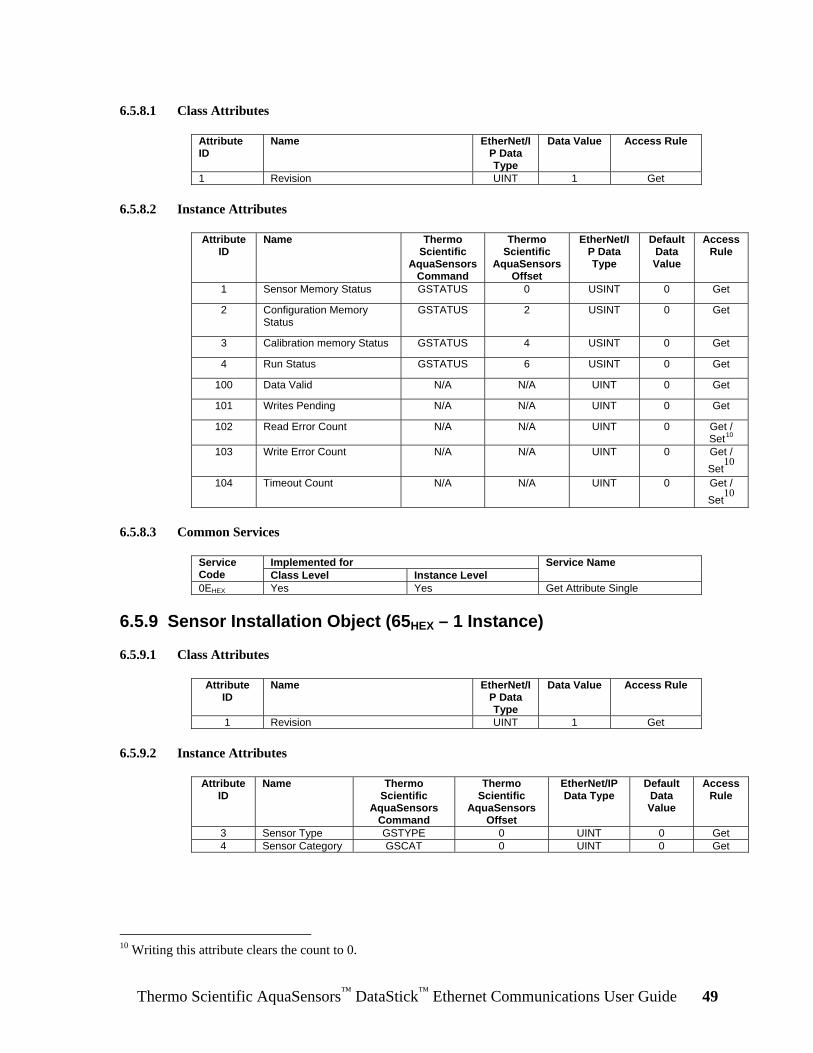
6.5.8.1 Class Attributes
Attribute ID
Name EtherNet/IP Data Type
Data Value
Access Rule
1 Revision UINT 1 Get
6.5.8.2 Instance Attributes
Attribute ID
Name Thermo Scientific
AquaSensors Command
Thermo Scientific
AquaSensors Offset
EtherNet/IP Data Type
Default Data Value
Access Rule
1 Sensor Memory Status GSTATUS 0 USINT 0 Get
2 Configuration Memory Status
GSTATUS 2 USINT 0 Get
3 Calibration memory Status GSTATUS 4 USINT 0 Get
4 Run Status GSTATUS 6 USINT 0 Get
100 Data Valid N/A N/A UINT 0 Get
101 Writes Pending N/A N/A UINT 0 Get
102 Read Error Count N/A N/A UINT 0 Get / Set10
103 Write Error Count N/A N/A UINT 0 Get / Set
10
104 Timeout Count N/A N/A UINT 0 Get / Set
10
6.5.8.3 Common Services
Implemented for Service Code Class Level Instance Level
Service Name
0EHEX Yes Yes Get Attribute Single
6.5.9 Sensor Installation Object (65HEX – 1 Instance)
6.5.9.1 Class Attributes
Attribute ID
Name EtherNet/IP Data Type
Data Value
Access Rule
1 Revision UINT 1 Get
6.5.9.2 Instance Attributes
Attribute ID
Name Thermo Scientific
AquaSensors Command
Thermo Scientific
AquaSensors Offset
EtherNet/IP Data Type
Default Data Value
Access Rule
3 Sensor Type GSTYPE 0 UINT 0 Get 4 Sensor Category GSCAT 0 UINT 0 Get
10 Writing this attribute clears the count to 0.
Thermo Scientific AquaSensors™ DataStick™ Ethernet Communications User Guide 50
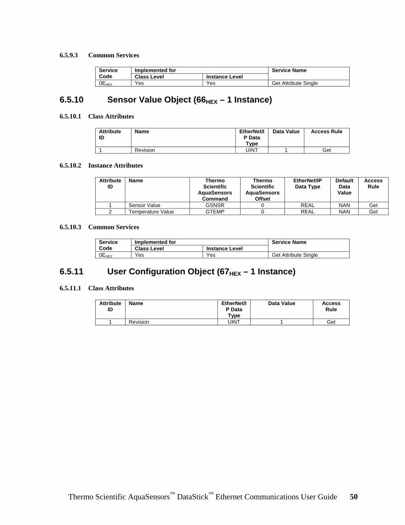
6.5.9.3 Common Services
Implemented for Service Code Class Level Instance Level
Service Name
0EHEX Yes Yes Get Attribute Single
6.5.10 Sensor Value Object (66HEX – 1 Instance)
6.5.10.1 Class Attributes
Attribute ID
Name EtherNet/IP Data Type
Data Value
Access Rule
1 Revision UINT 1 Get
6.5.10.2 Instance Attributes
Attribute ID
Name Thermo Scientific
AquaSensors Command
Thermo Scientific
AquaSensors Offset
EtherNet/IP Data Type
Default Data Value
Access Rule
1 Sensor Value GSNSR 0 REAL NAN Get 2 Temperature Value GTEMP 0 REAL NAN Get
6.5.10.3 Common Services
Implemented for Service Code Class Level Instance Level
Service Name
0EHEX Yes Yes Get Attribute Single
6.5.11 User Configuration Object (67HEX – 1 Instance)
6.5.11.1 Class Attributes
Attribute ID
Name EtherNet/IP Data Type
Data Value
Access Rule
1 Revision UINT 1 Get

Thermo Scientific AquaSensors™ DataStick™ Ethernet Communications User Guide 51
6.5.11.2 Instance Attributes
Attribute ID
Name Thermo Scientific
AquaSensors Command
Thermo Scientific
AquaSensors Offset
EtherNet/IP Data Type
Default Data Value
Access Rule
1 Main Serial Number GMSNO/ SMSNO
0 SHORT_STRING
0 Get / Set
2 Code Version GCVSN 0 SHORT_STRING
0 Get
3 Sensor Units GSUNITS / SSUNITS
0 UINT 0 Get / Set
4 Temperature Units GTUNITS / STUNITS
0 UINT 0 Get / Set
5 Sensor Filter GSFIL / SSFIL 0 UINT 0 Get / Set 6 Temperature Filter GTFIL / STFIL 0 UINT 0 Get / Set 7 pH Buffer Type GPHBUF /
SPHBUF 0 UINT 0 Get / Set
8 DO Salinity GSALT / SSALT 0 REAL NAN Get / Set 9 DO Pressure GPRESS /
SPRESS 0 REAL NAN Get / Set
10 Conductivity Reference Temperature
GCRTEMP / SCRTEMP
0 REAL NAN Get / Set
11 Conductivity Compensation Slope
GCCSLOPE / SCCSLOPE
0 REAL NAN Get / Set
12 Node Address GADDR / SADDR
0 USINT 0 Get / Set
13 DataStick Address GDSA / SDSA
0 UINT 0 Get / Set
14 DataStick Timeout (2 to 200) 10 msec. tick
NA NA UINT 0 Get / Set
15 TDS Conversion Factor GTDSF/STDSF 0 REAL NAN Get/Set
6.5.11.3 Common Services
Implemented for Service Code Class Level Instance Level
Service Name
0EHEX Yes Yes Get Attribute Single 10HEX No Yes Set Attribute Single
6.5.12 Generic Sensor Calibration Object (68HEX – 1 Instance) When calibrating the DataStick system, use the primary units of measure, e.g., calibrate pH in pH, not mV.
6.5.12.1 Class Attributes
Attribute ID
Name EtherNet/IP Data Type
Data Value
Access Rule
1 Revision UINT 1 Get

Thermo Scientific AquaSensors™ DataStick™ Ethernet Communications User Guide 52
6.5.12.2 Instance Attributes
Attribute ID
Name Thermo Scientific
AquaSensors Command
Thermo Scientific
AquaSensors Offset
EtherNet/IP Data Type
Default Data Value
Access Rule
1 Calibrate Sensor Zero CALSZERO None 0 Get / Set11
2 Calibrate 1-Point Sample CALS1PS, data REAL NAN Get / Set11
3 Calibrate Sensor 2-Point Sample Point
N/A UINT 0 Get / Set
4 Calibrate Sensor 2-Point Sample Value
CALS2PS, data1, data2
REAL NAN Get / Set11
5 Calibrate Sensor 1-Point Buffer CALS1PB None Get / Set11
6 Calibrate Sensor 2-Point Buffer CALS2PB, data UINT 0 Get / Set11
7 Calibrate Sensor in Air CALSAIR None Get / Set11
8 Calibrate Sensor Temperature 1-Point Sample
CALST1PS REAL NAN Get / Set11
9 Calibration Type CALSTATUS 3 UINT 0 Get 10 Calibration Status CALSTATUS 6 UINT 0 Get 11 Calibration Abort CALABORT N/A None 0 Get /
Set11
6.5.12.3 Common Services
Implemented for Service Code Class Level Instance Level
Service Name
0EHEX Yes No Get Attribute Single 10HEX No Yes Set Attribute Single
6.5.13 Conductivity Sensor Calibration Object (69HEX – 1 Instance)
6.5.13.1 Class Attributes
Attribute ID
Name EtherNet/IP Data Type
Data Value
Access Rule
1 Revision UINT 1 Get
6.5.13.2 Instance Attributes
Attribute ID
Name Thermo Scientific
AquaSensors Command
Thermo Scientific
AquaSensors Offset
EtherNet/IP Data Type
Default Data Value
Access Rule
1 Cell Constant GCELL / SCELL
0 REAL NAN Get/Set
6.5.13.3 Common Services
Implemented for Service Code Class Level Instance Level
Service Name
0EHEX Yes Yes Get Attribute Single 10HEX No Yes Set Attribute Single
11 Always reads as “0” since the parameter is write only.

Thermo Scientific AquaSensors™ DataStick™ Ethernet Communications User Guide 53
6.5.14 Mode Configuration Object (75HEX – 1 Instance)
6.5.14.1 Class Attributes
Attribute ID
Name EtherNet/IP Data Type
Data Value
Access Rule
1 Revision UINT 1 Get
6.5.14.2 Instance Attributes
Attribute ID
Name Thermo Scientific
AquaSensors Command
Thermo Scientific
AquaSensors Offset
EtherNet/IP Data Type
Default Data Value
Access Rule
2 PLC Data Type (format of Implicit data
object)
N/A N/A USINT 0 Get/Set
6.5.14.3 PLC Data Type
Value Type 0 Little Endian - ControlLogix 1 Little Endian Word Swap - SLC 2 Big Endian 3 Big Endian Word Swap
6.5.14.4 Common Services
Implemented for Service Code Class Level Instance Level
Service Name
0EHEX Yes Yes Get Attribute Single 10HEX No Yes Set Attribute Single
Please note that the PLC Data Type in the Mode Configuration Object affects only the implicit I/O of the EtherNet/IP; it has no effect on the Modbus TCP.
6.6 EtherNet/IP Reference Open DeviceNet Vendor Association (ODVA), http://www.odva.org/

Thermo Scientific AquaSensors™ DataStick™ Ethernet Communications User Guide 54
7 Modbus TCP and PCCC This section describes the Modbus TCP and Programmable Controller Communication Commands (PCCC).
7.1 Modbus TCP The product supports all measure, calibrate, configure and diagnose features of the DataStick via Modbus TCP.
According to the Modbus-IDA Website: The Modbus Protocol is a messaging structure developed by Modicon in 1979. It is used to establish master-slave/client-server communications between intelligent devices. It is a de facto standard, truly open and the most widely used network protocol in the industrial manufacturing environment. It has been implemented by hundreds of vendors on thousands of different devices to transfer discrete/analog I/O and register data between control devices. It's a lingua franca or common denominator between different manufacturers.
TCP/IP is the common transport protocol of the Internet and is actually a set of layered protocols, providing a reliable data transport mechanism between machines. Ethernet has become the de facto standard of corporate enterprise systems, so it comes as no surprise that it has also become the de facto standard for factory networking. Ethernet is not a new technology. It has matured to the point that the cost of implementing this network solution has been dropping to where its cost is commensurate with those of today's field-buses.
Using Ethernet TCP/IP in the factory allows true integration with the corporate intranet and MES systems that support the factory. To move Modbus into the 21st century, an open Modbus TCP/IP specification was developed in 1999. The protocol specification and implementation guide are available for download (www.modbus-ida.org/specs).
Combining a versatile, scaleable, and ubiquitous physical network (Ethernet) with a universal networking standard (TCP/IP) and a vendor-neutral data representation, Modbus gives a truly open, accessible network for exchange of process data.
The Modbus TCP registers are defined in the tables in Section 7.3,

Thermo Scientific AquaSensors™ DataStick™ Ethernet Communications User Guide 55
Modbus TCP and PCCC Register Map. For a detailed explanation of the register contents, please see the description of the associated DataStick Command in the DataStick Measurement System Instruction Manual, Catalog Number MAN011DS-4.
7.1.1 Modbus TCP Reference Modbus-IDA, http://www.modbus-ida.org/
7.2 Programmable Controller Communication Commands (PCCC)
This section describes how to communicate with an Ethernet product using an Allen-Bradley SLC 5/03, SLC 5/04 or SLC 5/05 PLC using Programmable Controller Communication Commands (PCCC).
The Ethernet product (server) mimics the behavior of a PLC5 in order to enable communications with a PLC5, SLC 5/03, SLC 5/04 or SLC 5/05 PLC (client). The PCCC object in the Ethernet product is accessed remotely using explicit messaging via EtherNet/IP. In order to read registers in the Ethernet product, the PLC must issue a Peer-To-Peer Read command to the Ethernet product. In order to write registers in the Ethernet product, the PLC must issue a Peer-To-Peer Write Command to the Ethernet product.
The PCCC Register numbers are shown in the tables in Section 7.3,
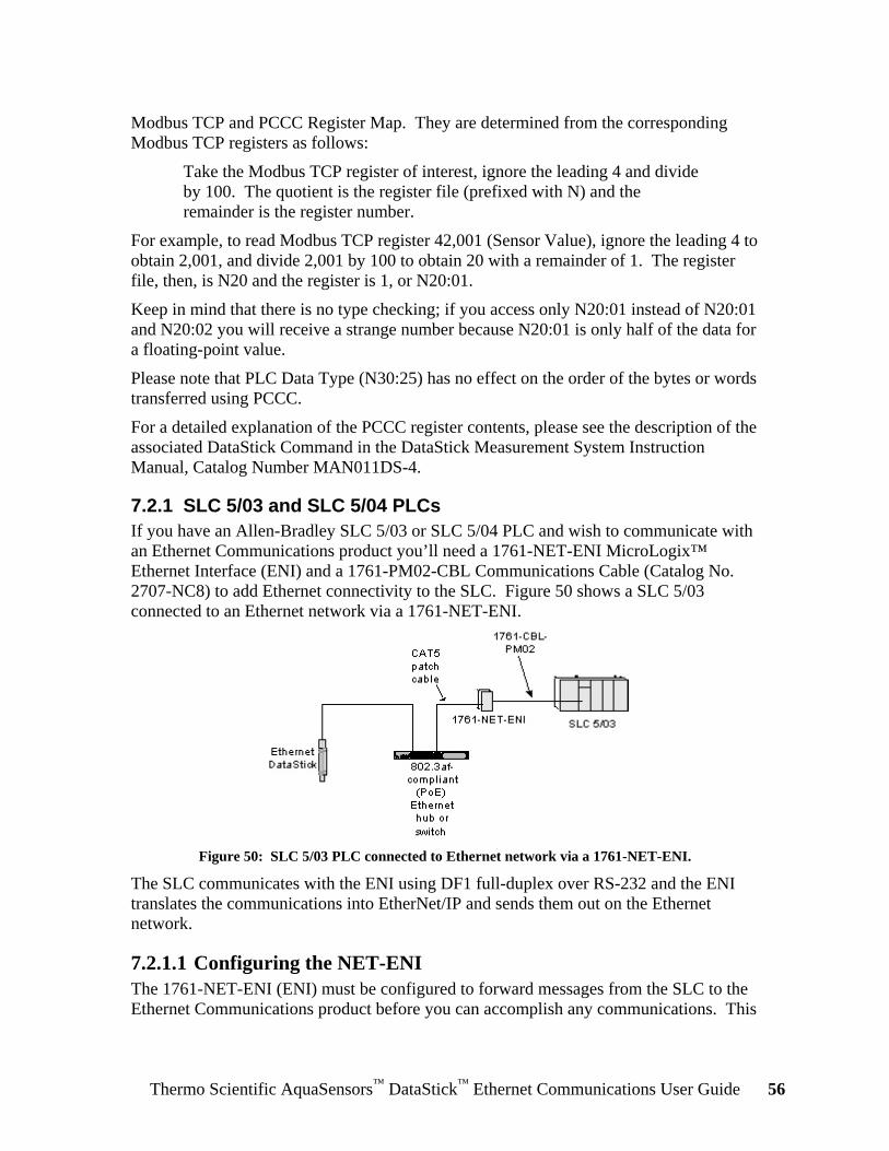
Thermo Scientific AquaSensors™ DataStick™ Ethernet Communications User Guide 56
Modbus TCP and PCCC Register Map. They are determined from the corresponding Modbus TCP registers as follows:
Take the Modbus TCP register of interest, ignore the leading 4 and divide by 100. The quotient is the register file (prefixed with N) and the remainder is the register number.
For example, to read Modbus TCP register 42,001 (Sensor Value), ignore the leading 4 to obtain 2,001, and divide 2,001 by 100 to obtain 20 with a remainder of 1. The register file, then, is N20 and the register is 1, or N20:01.
Keep in mind that there is no type checking; if you access only N20:01 instead of N20:01 and N20:02 you will receive a strange number because N20:01 is only half of the data for a floating-point value.
Please note that PLC Data Type (N30:25) has no effect on the order of the bytes or words transferred using PCCC.
For a detailed explanation of the PCCC register contents, please see the description of the associated DataStick Command in the DataStick Measurement System Instruction Manual, Catalog Number MAN011DS-4.
7.2.1 SLC 5/03 and SLC 5/04 PLCs If you have an Allen-Bradley SLC 5/03 or SLC 5/04 PLC and wish to communicate with an Ethernet Communications product you’ll need a 1761-NET-ENI MicroLogix™ Ethernet Interface (ENI) and a 1761-PM02-CBL Communications Cable (Catalog No. 2707-NC8) to add Ethernet connectivity to the SLC. Figure 50 shows a SLC 5/03 connected to an Ethernet network via a 1761-NET-ENI.
Figure 50: SLC 5/03 PLC connected to Ethernet network via a 1761-NET-ENI.
The SLC communicates with the ENI using DF1 full-duplex over RS-232 and the ENI translates the communications into EtherNet/IP and sends them out on the Ethernet network.
7.2.1.1 Configuring the NET-ENI The 1761-NET-ENI (ENI) must be configured to forward messages from the SLC to the Ethernet Communications product before you can accomplish any communications. This

Thermo Scientific AquaSensors™ DataStick™ Ethernet Communications User Guide 57
is done using the ENI Configuration Utility shown in Figure 51. It can be downloaded from http://www.ab.com/programmablecontrol/plc/micrologix1000/get/ENIutility.exe.
Figure 51: The ENI Configuration Utility.
See the 1761-NET-ENI MicroLogix™ Ethernet Interface User Manual for a complete description of how to configure the ENI.

Thermo Scientific AquaSensors™ DataStick™ Ethernet Communications User Guide 58
7.2.1.2 Com Port Redirector Software If you have a Series D 1761-NET-ENI (ENI), then it’s possible to configure the ENI via Ethernet using a software program called Com Port Redirector. This can be beneficial because the ENI can be re-configured without disconnecting it from the SLC. Com Port Redirector can be downloaded from http://www.ab.com/programmablecontrol/plc/micrologix1000/get/comredir.zip.
Figure 52 shows the Com Port Redirector configured to redirect COM32 on the computer to the ENI at IP address 192.168.10.60, port 10,001. The ENI Utility is configured to communicate with the ENI via COM32.
Figure 52: The Com Port Redirector.
Com Port Redirector creates a virtual COM port at COM32 and redirects any communications with COM32 to IP address 192.168.10.60, port 10,001.
7.2.2 Example SLC 5/03 Ladder Logic Programs The Message (MSG) instruction is used to communicate with the Ethernet product. It has a DN (Message done) bit that can be used to trigger the next operation. It also has an ER (Error) bit that can be used to handle communications errors. See the RSLogix 500 Instruction Help for more information.

Thermo Scientific AquaSensors™ DataStick™ Ethernet Communications User Guide 59
The example ladder logic programs in this section communicate with an Ethernet product through an ENI configured as shown in Figure 53.
Figure 53: The Message Routing tab of the ENI Configuration Utility.
When a MSG instruction from the PLC with a Local Node Address (Destn) of 9 arrives at the RS-232 port on the ENI, the ENI routes it to the Ethernet product at IP address 192.168.10.201.
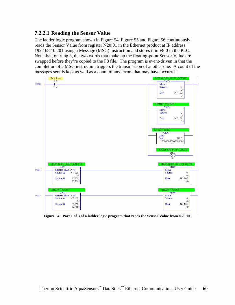
Thermo Scientific AquaSensors™ DataStick™ Ethernet Communications User Guide 60
7.2.2.1 Reading the Sensor Value The ladder logic program shown in Figure 54, Figure 55 and Figure 56 continuously reads the Sensor Value from register N20:01 in the Ethernet product at IP address 192.168.10.201 using a Message (MSG) instruction and stores it in F8:0 in the PLC. Note that, on rung 3, the two words that make up the floating-point Sensor Value are swapped before they’re copied to the F8 file. The program is event-driven in that the completion of a MSG instruction triggers the transmission of another one. A count of the messages sent is kept as well as a count of any errors that may have occurred.
Figure 54: Part 1 of 3 of a ladder logic program that reads the Sensor Value from N20:01.

Thermo Scientific AquaSensors™ DataStick™ Ethernet Communications User Guide 61
Figure 55: Part 2 of 3 of a ladder logic program that reads the Sensor Value from N20:01.
In the MSG instruction on rung 3, note that the Type is Peer-to-Peer and that it is a Read instruction. The “Target Device” must be set to PLC5.

Thermo Scientific AquaSensors™ DataStick™ Ethernet Communications User Guide 62
Figure 56: Part 3 of 3 of a ladder logic program that reads the Sensor Value from N20:01.
This program can be easily expanded to read the Temperature Value from N20:03 and N20:04.
Figure 57 shows the Setup screen for the MSG instruction on rung 3. The destination information is contained in the “This Controller” field. The “Data Table Address” is the register in the PLC where the Sensor Value is to be stored. Note that the “Size in Elements” is 2 because Sensor Value is a floating-point data type that occupies registers N20:01 and N20:02 in the Ethernet product. The Channel is 0 because this is the RS-232 port on the SLC to which the ENI is connected.
Figure 57: The Setup screen for a MSG instruction in a SLC 5/03.
The source information is shown in the “Target Device” field. The Message Timeout specifies the amount of time that the MSG instruction will wait for the Ethernet product to respond. Because of the way the ENI has been configured, a Local Node Address of 9 corresponds to IP address 192.168.10.201.

Thermo Scientific AquaSensors™ DataStick™ Ethernet Communications User Guide 63
Figure 58 shows the Sensor Value (7 pH) that was read from N20:01 and stored in F8:0.
Figure 58: The Sensor Value in F8:0.
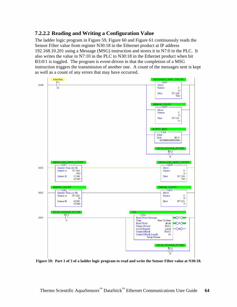
Thermo Scientific AquaSensors™ DataStick™ Ethernet Communications User Guide 64
7.2.2.2 Reading and Writing a Configuration Value The ladder logic program in Figure 59, Figure 60 and Figure 61 continuously reads the Sensor Filter value from register N30:18 in the Ethernet product at IP address 192.168.10.201 using a Message (MSG) instruction and stores it in N7:0 in the PLC. It also writes the value in N7:10 in the PLC to N30:18 in the Ethernet product when bit B3:0/1 is toggled. The program is event-driven in that the completion of a MSG instruction triggers the transmission of another one. A count of the messages sent is kept as well as a count of any errors that may have occurred.
Figure 59: Part 1 of 3 of a ladder logic program to read and write the Sensor Filter value at N30:18.

Thermo Scientific AquaSensors™ DataStick™ Ethernet Communications User Guide 65
Figure 60: Part 2 of 3 of a ladder logic program to read and write the Sensor Filter value at N30:18.
Note that the type of the MSG instruction on rung 6 is Write.

Thermo Scientific AquaSensors™ DataStick™ Ethernet Communications User Guide 66
Figure 61: Part 3 of 3 of a ladder logic program to read and write the Sensor Filter value at N30:18.
This program can easily be extended to read and write other configuration values.

Thermo Scientific AquaSensors™ DataStick™ Ethernet Communications User Guide 67
Figure 62 shows the Setup screen for the MSG instruction on rung 6. The source information is contained in the “This Controller” field. The “Data Table Address” is the register in the PLC where the new value is to be obtained. Note that the “Size in Elements” is 1 because the Sensor Filter value is an integer data type that occupies register N30:18 in the Ethernet product. The Channel is 0 because this is the RS-232 port on the SLC to which the ENI is connected.
Figure 62: The Setup screen for a MSG instruction in a SLC 5/03.
The destination information is shown in the “Target Device” field. The Message Timeout specifies the amount of time that the MSG instruction will wait for the Ethernet product to respond. Because of the way the ENI has been configured, a Local Node Address of 9 corresponds to IP address 192.168.10.201.
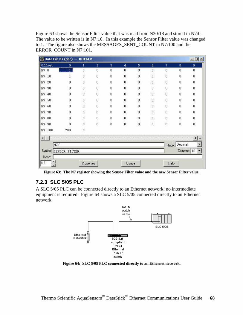
Thermo Scientific AquaSensors™ DataStick™ Ethernet Communications User Guide 68
Figure 63 shows the Sensor Filter value that was read from N30:18 and stored in N7:0. The value to be written is in N7:10. In this example the Sensor Filter value was changed to 1. The figure also shows the MESSAGES_SENT_COUNT in N7:100 and the ERROR_COUNT in N7:101.
Figure 63: The N7 register showing the Sensor Filter value and the new Sensor Filter value.
7.2.3 SLC 5/05 PLC A SLC 5/05 PLC can be connected directly to an Ethernet network; no intermediate equipment is required. Figure 64 shows a SLC 5/05 connected directly to an Ethernet network.
Figure 64: SLC 5/05 PLC connected directly to an Ethernet network.

Thermo Scientific AquaSensors™ DataStick™ Ethernet Communications User Guide 69
7.2.4 Example SLC 5/05 Ladder Logic Programs The ladder logic programs for a SLC 5/05 are very similar to the ladder logic programs shown in Section 7.2.2, Example SLC 5/03 Ladder Logic Programs. The main difference is in the Setup screen for the MSG instruction as shown in Figure 65.
Figure 65: The Setup screen for a MSG instruction in a SLC 5/05 PLC.

Thermo Scientific AquaSensors™ DataStick™ Ethernet Communications User Guide 70
Since the SLC 5/05 is connected directly to the Ethernet network, there’s no Local Node Address field in the “Target Device” section of the MSG Setup screen. Instead, if the MultiHop field is set to Yes, the IP address of the Ethernet product can be specified directly on the MultiHop tab as shown in Figure 66.
Figure 66: Specifying the IP address of the Ethernet product on the Setup screen of the SLC 5/05
MSG instruction.
Also, the Channel must be set to 1 instead of 0 so that the MSG instruction will be sent out the Ethernet port instead of the RS-232 port.
7.2.5 PCCC References • 1761-NET-ENI MicroLogix™ Ethernet Interface User Manual, Publication 1761-
UM006E-EN-P, http://literature.rockwellautomation.com/idc/groups/literature/documents/um/1761-um006_-en-p.pdf
• RSLogix 500 Instruction Help System • Communicating with RA Products Using EtherNet/IP Explicit Messaging,
http://www.rockwellautomation.com/enabled/pdf/eipexp1_2.pdf

Thermo Scientific AquaSensors™ DataStick™ Ethernet Communications User Guide 71
7.3 Modbus TCP and PCCC Register Map This section shows the register map for the Modbus TCP and the PCCC.
The PCCC registers are determined from the corresponding Modbus TCP registers as follows:
Take the Modbus TCP register number of interest, ignore the leading 4 and divide by 100. The quotient is the register file (prefixed with N) and the remainder is the register number.
For example, to read Modbus TCP register 42,001 (Sensor Value), ignore the leading 4 to obtain 2,001, and divide 2,001 by 100 to obtain 20 with a remainder of 1. The register file, then, is N20 and the register is 1, or N20:01.
In the tables in this section, each row contains two entries in the Register Number column; the top entry is the Modbus TCP register and the bottom entry is the PCCC register as shown in Figure 67. Both represent the same register in the Ethernet product.
Figure 67: The top entry is the Modbus TCP register
and the bottom entry is the PCCC register.
The Uptime registers shown in Table 4 indicate the elapsed time since the power was applied to the product. Table 4: Uptime registers. Register Number
Description Data Type
Access DataStickCommand
Comment Example Value
Variable Class
410,000 N100:00
Uptime in days
integer R N/A Elapsed time…
3 Information
410,001 N100:01
Uptime in hours
integer R N/A since last reset…
22 Information
410,002 N100:02
Uptime in minutes
integer R N/A or application…
47 Information
410,003 N100:03
Uptime in seconds
integer R N/A of power. 16 Information
Modbus TCP Register
PCCC Register

Thermo Scientific AquaSensors™ DataStick™ Ethernet Communications User Guide 72
Bank 1000 contains registers that are used for informational purposes only. Table 5: Register bank 1000; status registers. Register Number
Description Data Type
Access DataStick Command
Comment Example Value
VariableClass
41,001 N10:01
Communications Status
integer R N/A Status
41,002 N10:02
Calibration Status
integer R CALSTATUS Chars: 2; Offset: 6
1 Status
41,003 N10:03
Sensor Memory Status
integer R GSTATUS Chars: 1; Offset: 0
1 Status
41,004 N10:04
Configuration Memory Status
integer R GSTATUS Chars: 1; Offset: 2
1 Status
41,005 N10:05
Calibration Memory Status
integer R GSTATUS Chars: 1; Offset: 4
1 Status
41,006 N10:06
Run Status integer R GSTATUS Chars: 1; Offset: 6
1 Status
All of the registers in Bank 2000 contain floating-point values. Use these registers if the other devices on the network support floating-point values. If the other devices on the network do not support floating-point values, corresponding integer values can be found in Bank 3000.
If the product is not attached to a DataStick body, the Sensor Value (float) and the Temperature Value (float) shown in Table 6 will read “Not a Number” (NaN). Table 6: Register bank 2000; floating-point registers. Register Number
Description Data Type
Access DataStick Command
Comment Example Value Variable Class
42,001 N20:01
Sensor Value float R GSNSR 7.04 Process Value
42,002 N20:02
"
42,003 N20:03
Temperature Value
float R GTEMP 25.1 Process Value
42,004 N20:04
"
42,005 N20:05
Calibrate Sensor 1-
Point Sample Value
float R/W CALS1PS 7.02 Calibration
42,006 N20:06
"
42,007 N20:07
Calibrate Sensor 2-
Point Sample Value
float R/W CALS2PS 10.04 Calibration
42,008 N20:08
"
42,009 N20:09
Calibrate Temperature
1-Point
float R/W CALST1PS 25.3 Calibration
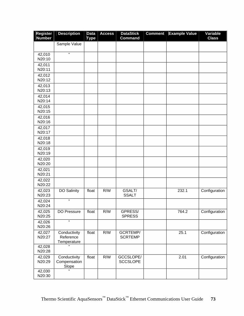
Thermo Scientific AquaSensors™ DataStick™ Ethernet Communications User Guide 73
Register Number
Description Data Type
Access DataStick Command
Comment Example Value Variable Class
Sample Value
42,010 N20:10
"
42,011 N20:11
42,012 N20:12
42,013 N20:13
42,014 N20:14
42,015 N20:15
42,016 N20:16
42,017 N20:17
42,018 N20:18
42,019 N20:19
42,020 N20:20
42,021 N20:21
42,022 N20:22
42,023 N20:23
DO Salinity float R/W GSALT/ SSALT
232.1 Configuration
42,024 N20:24
"
42,025 N20:25
DO Pressure float R/W GPRESS/ SPRESS
764.2 Configuration
42,026 N20:26
"
42,027 N20:27
Conductivity Reference
Temperature
float R/W GCRTEMP/ SCRTEMP
25.1 Configuration
42,028 N20:28
"
42,029 N20:29
Conductivity Compensation
Slope
float R/W GCCSLOPE/ SCCSLOPE
2.01 Configuration
42,030 N20:30
"
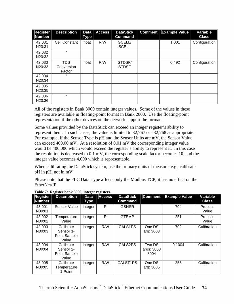
Thermo Scientific AquaSensors™ DataStick™ Ethernet Communications User Guide 74
Register Number
Description Data Type
Access DataStick Command
Comment Example Value Variable Class
42,031 N20:31
Cell Constant float R/W GCELL/ SCELL
1.001 Configuration
42,032 N20:32
"
42,033 N20:33
TDS Conversion
Factor
float R/W GTDSF/ STDSF
0.492 Configuration
42,034 N20:34
“
42,035 N20:35
42,036 N20:36
“
All of the registers in Bank 3000 contain integer values. Some of the values in these registers are available in floating-point format in Bank 2000. Use the floating-point representation if the other devices on the network support the format.
Some values provided by the DataStick can exceed an integer register’s ability to represent them. In such cases, the value is limited to 32,767 or –32,768 as appropriate. For example, if the Sensor Type is pH and the Sensor Units are mV, the Sensor Value can exceed 400.00 mV. At a resolution of 0.01 mV the corresponding integer value would be 400,000 which would exceed the register’s ability to represent it. In this case the resolution is decreased to 0.1 mV, the corresponding scale factor becomes 10, and the integer value becomes 4,000 which is representable.
When calibrating the DataStick system, use the primary units of measure, e.g., calibrate pH in pH, not in mV.
Please note that the PLC Data Type affects only the Modbus TCP; it has no effect on the EtherNet/IP. Table 7: Register bank 3000; integer registers. Register Number
Description Data Type
Access DataStick Command
Comment Example Value Variable Class
43,001 N30:01
Sensor Value integer R GSNSR 704 Process Value
43,002 N30:02
Temperature Value
integer R GTEMP 251 Process Value
43,003 N30:03
Calibrate Sensor 1-
Point Sample Value
integer R/W CALS1PS One DS arg: 3003
702 Calibration
43,004 N30:04
Calibrate Sensor 2-
Point Sample Value
integer R/W CALS2PS Two DS args: 3008
3004
0 1004 Calibration
43,005 N30:05
Calibrate Temperature
1-Point
integer R/W CALST1PS One DS arg: 3005
253 Calibration

Thermo Scientific AquaSensors™ DataStick™ Ethernet Communications User Guide 75
Register Number
Description Data Type
Access DataStick Command
Comment Example Value Variable Class
Sample Value
43,006 N30:06
Calibrate Sensor 1-
Point Buffer
integer R/W CALS1PB No DS arguments
N/A Calibration
43,007 N30:07
Calibrate Sensor 2-
Point Buffer
integer R/W CALS2PB One DS arg: 3007
0 Calibration
43,003 N30:08
Calibrate Sensor 2-
Point Sample Point
integer R/W N/A 0 Calibration
43,009 N30:09
Calibrate Sensor in Air
integer R/W CALSAIR No DS arguments
N/A Calibration
43,010 N30:10
Calibrate Sensor Zero
integer R/W CALSZERO No DS arguments
N/A Calibration
43,011 N30:11
Calibration Abort
integer R/W CALABORT No DS arguments
N/A Calibration
43,012 N30:12
DO Salinity integer R/W GSALT/ SSALT
2321 Configuration
43,013 N30:13
DO Pressure integer R/W GPRESS/ SPRESS
7642 Configuration
43,014 N30:14
Conductivity Reference
Temperature
integer R/W GCRTEMP/ SCRTEMP
251 Configuration
43,015 N30:15
Conductivity Compensation
Slope
integer R/W GCCSLOPE/ SCCSLOPE
201 Configuration
43,016 N30:16
Cell Constant integer R/W GCELL/ SCELL
1001 Configuration
43,017 N30:17
Sensor Units integer R/W GSUNITS/ SSUNITS
Sensor Head-
dependent
0 Configuration
43,018 N30:18
Sensor Filter integer R/W GSFIL/ SSFIL
1 Configuration
43,019 N30:19
Temperature Units
integer R/W GTUNITS/ STUNITS
0 Configuration
43,020 N30:20
Temperature Filter
integer R/W GTFIL/ STFIL
1 Configuration
43,021 N30:21
pH Buffer Type
integer R/W GPHBUF/ SPHBUF
0 Configuration
43,022 N30:22
43,032 N30:23
43,024 N30:24

Thermo Scientific AquaSensors™ DataStick™ Ethernet Communications User Guide 76
Register Number
Description Data Type
Access DataStick Command
Comment Example Value Variable Class
43,025 N30:25
PLC Data Type
integer R/W N/A Big Endian
1 Configuration
43,026 N30:26
Timeout integer R/W N/A ms 500 Configuration
43,027 N30:27
43,028 N30:28
TDS Conversion
Factor
integer R/W GTDSF/ STDSF
49 Configuration
43,029 N30:29
43,030 N30:30
MAC Address integer R/W N/A Writable only...
Configuration
43,031 N30:31
“ integer R/W N/A if 0. Configuration
43,032 N30:32
“ integer R/W N/A Configuration
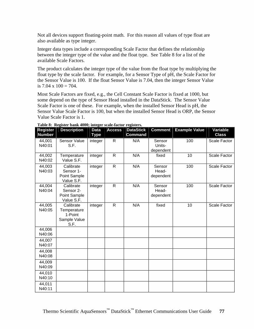
Thermo Scientific AquaSensors™ DataStick™ Ethernet Communications User Guide 77
Not all devices support floating-point math. For this reason all values of type float are also available as type integer.
Integer data types include a corresponding Scale Factor that defines the relationship between the integer type of the value and the float type. See Table 8 for a list of the available Scale Factors.
The product calculates the integer type of the value from the float type by multiplying the float type by the scale factor. For example, for a Sensor Type of pH, the Scale Factor for the Sensor Value is 100. If the float Sensor Value is 7.04, then the integer Sensor Value is 7.04 x 100 = 704.
Most Scale Factors are fixed, e.g., the Cell Constant Scale Factor is fixed at 1000, but some depend on the type of Sensor Head installed in the DataStick. The Sensor Value Scale Factor is one of these. For example, when the installed Sensor Head is pH, the Sensor Value Scale Factor is 100, but when the installed Sensor Head is ORP, the Sensor Value Scale Factor is 1. Table 8: Register bank 4000; integer scale-factor registers. Register Number
Description Data Type
Access DataStickCommand
Comment Example Value Variable Class
44,001 N40:01
Sensor Value S.F.
integer R N/A Sensor Units-
dependent
100 Scale Factor
44,002 N40:02
Temperature Value S.F.
integer R N/A fixed 10 Scale Factor
44,003 N40:03
Calibrate Sensor 1-
Point Sample Value S.F.
integer R N/A Sensor Head-
dependent
100 Scale Factor
44,004 N40:04
Calibrate Sensor 2-
Point Sample Value S.F.
integer R N/A Sensor Head-
dependent
100 Scale Factor
44,005 N40:05
Calibrate Temperature
1-Point Sample Value
S.F.
integer R N/A fixed 10 Scale Factor
44,006 N40:06
44,007 N40:07
44,008 N40:08
44,009 N40:09
44,010 N40:10
44,011 N40:11
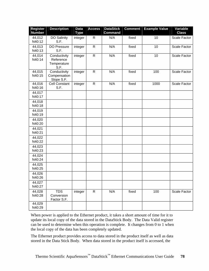
Thermo Scientific AquaSensors™ DataStick™ Ethernet Communications User Guide 78
Register Number
Description Data Type
Access DataStickCommand
Comment Example Value Variable Class
44,012 N40:12
DO Salinity S.F.
integer R N/A fixed 10 Scale Factor
44,013 N40:13
DO Pressure S.F.
integer R N/A fixed 10 Scale Factor
44,014 N40:14
Conductivity Reference
Temperature S.F.
integer R N/A fixed 10 Scale Factor
44,015 N40:15
Conductivity Compensation
Slope S.F.
integer R N/A fixed 100 Scale Factor
44,016 N40:16
Cell Constant S.F.
integer R N/A fixed 1000 Scale Factor
44,017 N40:17
44,018 N40:18
44,019 N40:19
44,020 N40:20
44,021 N40:21
44,022 N40:22
44,023 N40:23
44,024 N40:24
44,025 N40:25
44,026 N40:26
44,027 N40:27
44,028 N40:28
TDS Conversion Factor S.F.
integer R N/A fixed 100 Scale Factor
44,029 N40:29
When power is applied to the Ethernet product, it takes a short amount of time for it to update its local copy of the data stored in the DataStick Body. The Data Valid register can be used to determine when this operation is complete. It changes from 0 to 1 when the local copy of the data has been completely updated.
The Ethernet product provides access to data stored in the product itself as well as data stored in the Data Stick Body. When data stored in the product itself is accessed, the
Thermo Scientific AquaSensors™ DataStick™ Ethernet Communications User Guide 79
success or failure of the operation is indicated immediately. When data stored in the DataStick Body is accessed, the immediate indication is success even though the overall operation may have failed. This is because the protocol being used doesn’t tolerate the kind of delays necessary to accomplish an access of this type. To assist the programmer in determining the overall success or failure of accessing DataStick Body data, four counter registers are available:
5. Pending Writes
6. Read Error Count
7. Write Error Count
8. Timeout Count
The Pending Writes is incremented every time the Ethernet product has been asked to write to the DataStick but has not yet completed the operation. The count is decremented each time a write completes.
The Read Error Count is incremented every time the Ethernet product receives an error while trying to read from the DataStick Body. It is a count of the total number of read errors for all of the protocols supported. Some DataStick Body data might not be available depending on the type of Sensor Head installed. When the Ethernet product tries to read this unavailable data the DataStick will respond with an error and this will cause the Read Error Count to be incremented. The Ethernet product will realize that this data is unavailable and stop requesting it.
The Write Error Count is incremented every time the Ethernet product receives an error while trying to write to the DataStick. It is a count of the total number of write errors for all of the protocols supported. For instance, if an attempt is made to change the Sensor Filter value to 200, the DataStick will respond with an error because the largest acceptable value is 100 and this will cause the Write Error Counter to be incremented.
The Timeout Count is incremented every time the Ethernet product fails to receive a response from the DataStick in a reasonable amount of time. It is a count of the total number of write errors for all of the protocols supported.
The counters can be cleared to 0 by writing to them.
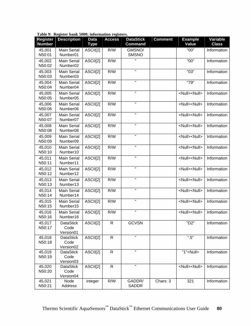
Thermo Scientific AquaSensors™ DataStick™ Ethernet Communications User Guide 80
Table 9: Register bank 5000; information registers. Register Number
Description Data Type
Access DataStick Command
Comment Example Value
Variable Class
45,001 N50:01
Main Serial Number01
ASCII[2] R/W GMSNO/ SMSNO
"00" Information
45,002 N50:02
Main Serial Number02
ASCII[2] R/W " "00" Information
45,003 N50:03
Main Serial Number03
ASCII[2] R/W " "03" Information
45,004 N50:04
Main Serial Number04
ASCII[2] R/W " "79" Information
45,005 N50:05
Main Serial Number05
ASCII[2] R/W " <Null><Null> Information
45,006 N50:06
Main Serial Number06
ASCII[2] R/W " <Null><Null> Information
45,007 N50:07
Main Serial Number07
ASCII[2] R/W " <Null><Null> Information
45,008 N50:08
Main Serial Number08
ASCII[2] R/W " <Null><Null> Information
45,009 N50:09
Main Serial Number09
ASCII[2] R/W " <Null><Null> Information
45,010 N50:10
Main Serial Number10
ASCII[2] R/W " <Null><Null> Information
45,011 N50:11
Main Serial Number11
ASCII[2] R/W " <Null><Null> Information
45,012 N50:12
Main Serial Number12
ASCII[2] R/W " <Null><Null> Information
45,013 N50:13
Main Serial Number13
ASCII[2] R/W " <Null><Null> Information
45,014 N50:14
Main Serial Number14
ASCII[2] R/W " <Null><Null> Information
45,015 N50:15
Main Serial Number15
ASCII[2] R/W " <Null><Null> Information
45,016 N50:16
Main Serial Number16
ASCII[2] R/W " <Null><Null> Information
45,017 N50:17
DataStick Code
Version01
ASCII[2] R GCVSN "D2" Information
45,018 N50:18
DataStick Code
Version02
ASCII[2] R " ".5" Information
45,019 N50:19
DataStick Code
Version03
ASCII[2] R " "1"<Null> Information
45,020 N50:20
DataStick Code
Version04
ASCII[2] R " <Null><Null> Information
45,021 N50:21
Node Address
integer R/W GADDR/ SADDR
Chars: 3 321 Information

Thermo Scientific AquaSensors™ DataStick™ Ethernet Communications User Guide 81
Register Number
Description Data Type
Access DataStick Command
Comment Example Value
Variable Class
45,022 N50:22
Sensor Type
integer R GSTYPE Chars: 2 1 Information
45,023 N50:23
Calibration Type
integer R CALSTATUS Chars: 2; Offset: 3
4 Information
45,024 N50:24
Comms Adapter
Code Version
integer R N/A V3.03 0x0303 Information
45,025 N50:25
45,026 N50:26
Location01 ASCII[2] R/W N/A Also... "TA" Information
45,027 N50:27
Location02 ASCII[2] R/W N/A readable… "NK" Information
45,028 N50:28
Location03 ASCII[2] R/W N/A by… "#3" Information
45,029 N50:29
Location04 ASCII[2] R/W N/A Discovery… "BL" Information
45,030 N50:30
Location05 ASCII[2] R/W N/A Tool. "DG" Information
45,031 N50:31
Location06 ASCII[2] R/W N/A “ "#8" Information
45,032 N50:32
Location07 ASCII[2] R/W N/A “ Information
45,033 N50:33
Location08 ASCII[2] R/W N/A “ Information
45,034 N50:34
Data Valid integer R N/A Information
45,035 N50:35
Pending Writes
integer R N/A Information
45,036 N50:36
Read Error Count
integer R/W N/A Resets to 0 on write
Information
45,037 N50:37
Write Error Count
integer R/W N/A Resets to 0 on write
Information
45,038 N50:38
Timeout Count
integer R/W N/A Resets to 0 on write
Information
When the Ethernet option is present in the AV38 Local Display, the register in Table 10 can be used to change the address of the DataStick with which the AV38 is communicating. In this way, a device on the Ethernet network can access a DataStick that’s connected to the AV38. Table 10: Register bank 6000; AV38 configuration register. Register Number
Description Data Type
Access DataStickCommand
Comment Example Value
Variable Class
46,001 N60:01
DataStick Slave
Address
integer R/W GDSA/ SDSA
123 AV38 Configuration
Thermo Scientific AquaSensors™ DataStick™ Ethernet Communications User Guide 82
8 Certifications The products are designed to pass:
• the ODVA-approved conformance tests for an EtherNet/IP Node Device • the Modbus-IDA Conformance Test Program
9 General References • IEEE Standard 802.3, 10Base-T Ethernet,
http://standards.ieee.org/getieee802/index.html • IEEE Standard 802.3af, Power Over Ethernet,
http://standards.ieee.org/getieee802/index.html • TIA/EIA-568-B, Commercial Building Telecommunications Cabling Standard,
http://www.tiaonline.org/ • DataStick Measurement System Instruction Manual

Thermo Scientific AquaSensors™ DataStick™ Ethernet Communications User Guide 83
10 Limited Warranty
WARRANTY/REPLACEMENT PLAN
Thermo Fisher Scientific warrants its Smart Communications Adapters against material and workmanship defect for a period of one year from the date of shipment. In the event that a defect is discovered during the warranty period, Thermo Fisher Scientific agrees, at its option, to repair or replace the defective product. Any product repaired or replaced under this warranty will be warranted only for the remainder of the original product warranty period. This warranty does not apply to consumable products associated with this product including, but not limited to, chemical reagents and salt bridges. Products may not be returned without authorization from Thermo Fisher Scientific. To obtain authorization, please call Thermo Fisher Scientific for a return material authorization number. Limitations: This warranty does not cover:
1. Damage caused by misuse, neglect (lack of appropriate maintenance), alteration, accident or improper application or installation.
2. Damage caused by any repair or attempted repair not authorized by Thermo Fisher Scientific. 3. Any product not used in accordance with the instructions furnished by Thermo Fisher
Scientific. 4. Damage caused by acts of God, natural disaster, acts of war (declared or undeclared), acts of
terrorism, work actions, or acts of any governmental jurisdiction. 5. Freight charges to return merchandise to Thermo Fisher Scientific. 6. Travel fees associated with on-site warranty repair.
This warranty is the sole expressed warranty made by Thermo Fisher Scientific in connection with its products. All other warranties, whether expressed or implied, including without limitation, the warranties of merchantability and fitness for a particular purpose, are expressly disclaimed. The liability of Thermo Fisher Scientific shall be limited to the cost of the item giving rise to the claim. In no event shall Thermo Fisher Scientific be liable for incidental or consequential damages. This warranty is the sole and complete warranty for Thermo Fisher Scientific. No person is authorized to make any warranties or representations on behalf of Thermo Fisher Scientific. Thermo Fisher Scientific reserves the right to change or modify this warranty at any time.

Thermo Scientific AquaSensors™ DataStick™ Ethernet Communications User Guide 84
11 Terms and Conditions
Terms and Conditions of Sale The following terms and conditions will be presumed acceptable unless changes are made in writing and accepted by both parties in a reasonable amount of time. Any standard or boilerplate terms and conditions supplied with a written purchase order will not be applicable unless accepted in writing by both parties. Quotations: All quotations shall be in writing. Written quotations shall be valid for 30 days from the date issued. Verbal quotations or price lists are not valid. Pricing: All pricing is in US Dollars. Thermo Fisher Scientific reserves the right to change pricing without notice. Terms: Payment terms are net 30 days from the date of invoice with approved credit. Thermo Fisher Scientific reserves the right to deny credit or revoke previously extended credit. Past due accounts are subject to interest charges. Other acceptable payment terms are cash, certified check, money order, credit card or letter of credit confirmed by any United States of America bank. Other payment terms are not valid unless accepted in writing. Sales taxes shall be included on the invoice unless a valid tax exemption certificate is supplied. Return Material Authorization: Contact Thermo Fisher Scientific Customer Service for a Return Material Authorization (RMA) number. Items returned without an RMA number will be rejected. All returned merchandise must be in unused, resalable condition, and must not be contaminated with hazardous materials. Cancelled orders must be returned within 30 days of the date on the invoice and shall be subject to expenses incurred that may include, but are not limited to, inspection and restocking fees. Items returned within 60 days shall be subject to a restocking charge that is equal to 15% of the purchase price. Items returned after more than 60 days shall be subject to a restocking charge equal to 25% of the purchase price. Thermo Fisher Scientific reserves the right to reject any return that is not under warranty after 60 days. Non-stock items are normally not returnable. Transportation: Orders are shipped FOB Thermo Fisher Scientific, or factory, by the most efficient means available. Appropriate charges, such as freight and insurance will be added to invoices. All shipments will be insured. Goods damaged in shipment must be reported by the recipient to the freight carrier for claims.


Thermo Fisher Scientific
Environmental Instruments Process Water Instruments
North America 166 Cummings Center Beverly, MA 01915 USA Toll Free: 1-800-225-1480 Tel: 1-978-232-6000 Dom. Fax: 1-978-232-6015 Int’l Fax: 978-232-6031
EuropeP.O. Box 254, 3860 AG Nijkerk Wallerstraat 125K, 3862 BN Nijkerk, Netherlands Tel: (31) 033-2463887 Fax: (31) 033-2460832
Asia PacificBlk 55, Ayer Rajah Crescent #04-16/24, Singapore 139949 Tel: 65-6778-6876 Fax: 65-6773-0836
www.thermo.com/processwater
© 2009 Thermo Fisher Scientific Inc. All rights reserved.
258489-001 Rev. A 01-09