SAFETY GEAR SLC 2500 - Inicio | Grupo...
13
SLC (SCHLOSSER LUEZAR & CVR, S.L.) SAFETY GEAR SLC 2500 ASSEMBLY MANUAL
Transcript of SAFETY GEAR SLC 2500 - Inicio | Grupo...

SLC (SCHLOSSER LUEZAR & CVR, S.L.)
SAFETY GEAR SLC 2500 ASSEMBLY MANUAL

SAFETY GEAR SLC 2500 MM.SLC250.01S
Revision 3
05/01/2012
Page 2 / 13 ASSEMBLY MANUAL
SCHLOSSER LUEZAR & CVR SL. Pol. Malpica, C/F Oeste, nave 7 (Grupo Quejido) 50016 Zaragoza (España) Telf: +34 976 570 976
SICHERHEITSPAKETE - SAFETY PACKAGES - CONJUNTOS DE SEGURIDAD
INDEX
1 General aspects ............................................................................................................................................... 3
2 Safetygear installation ..................................................................................................................................... 4
2.1 Previous instructions ............................................................................................................................... 4
2.2 Assembly instructions for safety gears including SLC linkage ................................................................ 6
2.3 Assembly instructions for other cases ..................................................................................................... 9
3 Use and maintenance. ................................................................................................................................... 10
3.1 Guide rails .............................................................................................................................................. 10
3.2 Overspeed governor .............................................................................................................................. 10
3.3 Use range ............................................................................................................................................... 10
3.4 Braking parts replacement. ................................................................................................................... 11
3.5 Maintenance .......................................................................................................................................... 11
3.5.1 Cleaning ......................................................................................................................................... 11
3.5.2 Corrosion ....................................................................................................................................... 11
Annex I SLC-2500 safety gear dimensions ..................................................................................................... 12
Annex II Engagement and rest roller positions ............................................................................................... 13

SAFETY GEAR SLC 2500 MM.SLC250.01S
Revision 3
05/01/2012
Page 3 / 13 ASSEMBLY MANUAL
SCHLOSSER LUEZAR & CVR SL. Pol. Malpica, C/F Oeste, nave 7 (Grupo Quejido) 50016 Zaragoza (España) Telf: +34 976 570 976
SICHERHEITSPAKETE - SAFETY PACKAGES - CONJUNTOS DE SEGURIDAD
1 General aspects
The SLC-2500 safety gear has been designed and certified to be used in a wide range of loads, for drawned and
mechanised guide rails, dry or oiled. There are two available versions according to the rated speed and
trigging speed : SLC-2500-S and SLC-2500-HS :
SLC-2500-S SLC-2500-HS
Rated speed (max.) 1,7 m/s 2,6 m/s
Trigging speed (máx.) 2,0 m/s 3,0 m/s
P+Q máx. 2819 kg 2819 kg
P+Q mín. 339 kg 339 kg
Guide thickness 5 - 16 mm 5 - 16 mm
Guide rail Drawn/ mechanised Drawn/ mechanised
Lubrication Oiled / Dry Oiled / Dry
Dimensions 100x200x45 100x200x45
Table 1
Everything in this manual indicated is valid for both models (S y HS).
The safety blocks are adjusted and provided according to the customer requirements, so they can be only used
in installations with the same parameters as indicated in the order:
P+Q (kg).
Guide thickness.
Minimum guide braking width.
Guide lubrication.
Upwards braking Force
Please check that the data on the safety label is according to installation parameters.
The user must check that the data on the label and the attached documents are according to the lift
parameters.
Image 1 Label

SAFETY GEAR SLC 2500 MM.SLC250.01S
Revision 3
05/01/2012
Page 4 / 13 ASSEMBLY MANUAL
SCHLOSSER LUEZAR & CVR SL. Pol. Malpica, C/F Oeste, nave 7 (Grupo Quejido) 50016 Zaragoza (España) Telf: +34 976 570 976
SICHERHEITSPAKETE - SAFETY PACKAGES - CONJUNTOS DE SEGURIDAD
S = S: standard, HS: High speed
Max rated speed = Maximum trigging speed
F. Nr = Fabrication number
F. Date = Manufacturing date
(P+Q) = Lift P+Q
E = Drawn guide
C = Mechanised guide
= Oiled guide (Yes / No)
Table 2
The parameters have been printed by using undeletable ink , and the label is placed on the safety plates.
Forbidden:
a) Assembly safety gears with different fabrication number (right and left).
b) Using a safety gear for an installation with different parameters to the ones indicated on the label.
c) Handle over any part of the safety block, without Luezar-Eco S.L. ‘s authorization
SLC (SCHLOSSER LUEZAR & CVR SL.) and LUEZAR-ECO, S.L. will not be responsible for the damages caused for
the non-fulfilment of the aspects in this manual indicated or the violation of the standard and rules.
SLC (SCHLOSSER LUEZAR & CVR SL.) keeps the right of modifying this document without previous notice. The
last version of the document will be the only valid, and this one replaces the previous version.
2 Safety gear installation
2.1 Previous instructions
SLC 2500 safety gear can be installed in a fixed or oscillating way. We advise using the oscillating system, as it
allows a more precise adjustment of the safety gear position regarding the guide rail, and it also allows the
safety gear a good adaptation to guide while braking process. The frame should be strong enough to afford the
braking strength. And with fixed system, the frame or the guide shoes should also afford the distortion.
The frame beams must be drilled in order to fix the safety gear according to Annex I (pg. 12).
SAFETY GEAR SLC 2500 MM.SLC250.01S
Revision 3
05/01/2012
Page 5 / 13 ASSEMBLY MANUAL
SCHLOSSER LUEZAR & CVR SL. Pol. Malpica, C/F Oeste, nave 7 (Grupo Quejido) 50016 Zaragoza (España) Telf: +34 976 570 976
SICHERHEITSPAKETE - SAFETY PACKAGES - CONJUNTOS DE SEGURIDAD
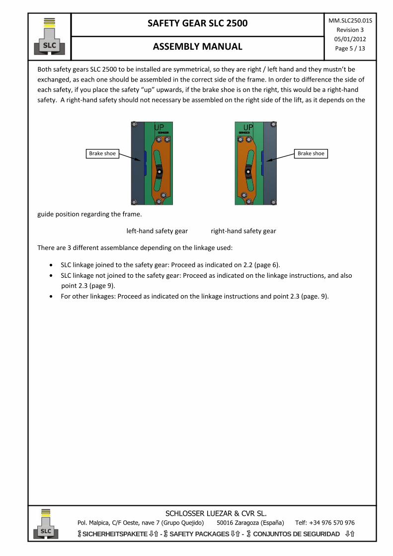
Both safety gears SLC 2500 to be installed are symmetrical, so they are right / left hand and they mustn’t be
exchanged, as each one should be assembled in the correct side of the frame. In order to difference the side of
each safety, if you place the safety “up” upwards, if the brake shoe is on the right, this would be a right-hand
safety. A right-hand safety should not necessary be assembled on the right side of the lift, as it depends on the
guide position regarding the frame.
left-hand safety gear right-hand safety gear
There are 3 different assemblance depending on the linkage used:
SLC linkage joined to the safety gear: Proceed as indicated on 2.2 (page 6).
SLC linkage not joined to the safety gear: Proceed as indicated on the linkage instructions, and also
point 2.3 (page 9).
For other linkages: Proceed as indicated on the linkage instructions and point 2.3 (page. 9).
Brake shoe Brake shoe

SAFETY GEAR SLC 2500 MM.SLC250.01S
Revision 3
05/01/2012
Page 6 / 13 ASSEMBLY MANUAL
SCHLOSSER LUEZAR & CVR SL. Pol. Malpica, C/F Oeste, nave 7 (Grupo Quejido) 50016 Zaragoza (España) Telf: +34 976 570 976
SICHERHEITSPAKETE - SAFETY PACKAGES - CONJUNTOS DE SEGURIDAD
2.2 Assembly instructions for safety gears including SLC linkage
Step 1 Place the safety switch
Fix the safety switch Connect the safety switch, and test that, when moving the rod, the switch works properly
Step 2 Fix the safety gear to the frame
The UP mark stamped onto the safety gear must be always placed on the upper side. Check this before
and after the assemblance.
The SLC2500 safety gear must be placed on the frame in the way that the position regarding the guide is as
indicated in Annex I (pg. 12). These dimensions should be checked after the installation. In order to make
easier the installation, it can be used gauges, which should be removed after installation.
Anyway all the screws used to fix the safety gear to the frame must be 8.8 quality.
There are 2 possibilities for assembly:
- Oscillating system assembly: proceed as indicated on the oscillating system instructions.
- Fix system assembly: proceed as following:
- Put, for each safety gear, 4 Screws DIN933 M12 8.8 and 4
washers DIN 127 or similar, into the threaded holes
from the safety gear. In any case the total screw’s
length (L*) must allow a threaded length inside the
hole between 12 and 14 mm.
DIN 6923 M4
DIN 84 M4x35
Safety
switch
DIN 933 M12xL*
+ DIN 127 M12

SAFETY GEAR SLC 2500 MM.SLC250.01S
Revision 3
05/01/2012
Page 7 / 13 ASSEMBLY MANUAL
SCHLOSSER LUEZAR & CVR SL. Pol. Malpica, C/F Oeste, nave 7 (Grupo Quejido) 50016 Zaragoza (España) Telf: +34 976 570 976
SICHERHEITSPAKETE - SAFETY PACKAGES - CONJUNTOS DE SEGURIDAD
Step 3 Transmission bar adjustment
Transmission bar must consist of a squared bar, 5x15mm, with enough
length so the bar must protrude both sides about 15mm the linkage (and
also the governor, if this one is attached to the linkage).
Put the transmission bas through the linkage bushes (maybe you should
loose the setscrew first). Place the bar so it protrudes about 15mm, and
then tighten again the setscrews, in order to fix the bar.
Step 4 Adjust the roller position
Check the roller position in both safety gears. The roller must be placed on the central zone, exactly to 79,5mm
from the bottom of the block. On the SLC linkages with horizontal edge, and always that the roller cannot be
seen, you can take this edge as a reference to check the right roller position.
If the roller must be adjusted loose (not releasing) the rod screws, move the rod until getting the right roller
position, (the SLC rods have a ± 1,25° regulation), and tighten again the screws.
Setscrew
Transmission bar
The bar should protrude min 15mm
Bush
Regulation
± 1,25°
Rod screw
Rod horizontal edge

SAFETY GEAR SLC 2500 MM.SLC250.01S
Revision 3
05/01/2012
Page 8 / 13 ASSEMBLY MANUAL
SCHLOSSER LUEZAR & CVR SL. Pol. Malpica, C/F Oeste, nave 7 (Grupo Quejido) 50016 Zaragoza (España) Telf: +34 976 570 976
SICHERHEITSPAKETE - SAFETY PACKAGES - CONJUNTOS DE SEGURIDAD
Step 5 Adjust the recover strength
The SLC linkage recover system can be adjusted, so you can regulate the necessary strength you need for
actuating on the rod. In order to regulate this strength loose/tighten the nut as showed in picture:
After regulating the recover system, check that
the spring has not been highly compressed. The
rod should get the engaging positions before
the spring is completely compressed. An
excessive tighten of the spring could cause the
system
Step 6 Check working
Finally it’s very important to check that the assembly has been correctly made and all the parts work properly.
So you should move with your hand the linkage, up and down (simulating upwards and downwards actioning)
checking the following:
The safety gear is right positioned regarding the guide.
Both rollers get the engagement positions, and also they do it at the same time.
The movement is made without interferences from other parts.
The linkage recover system is able to recover by its own the roller rest position (otherwise see step 2
page 8).
The safety gear switch works properly.
Note: In Annex I (pg. 12) position of the block regarding the guide is indicated. In Annex II (Pg. 13) engagement
and rest roller positions are indicated.
Adjustment nut

SAFETY GEAR SLC 2500 MM.SLC250.01S
Revision 3
05/01/2012
Page 9 / 13 ASSEMBLY MANUAL
SCHLOSSER LUEZAR & CVR SL. Pol. Malpica, C/F Oeste, nave 7 (Grupo Quejido) 50016 Zaragoza (España) Telf: +34 976 570 976
SICHERHEITSPAKETE - SAFETY PACKAGES - CONJUNTOS DE SEGURIDAD
2.3 Assembly instructions for other cases
In order to fix the safety gear to the frame, proceed according to Step 2 (Pg. 6).
The way to join the linkage and the safety gear may be different, but the most common options are:
o Roller with pin (most common): In case the roller includes a pin, the linkage should have a hole
available for introducing the pin into. (The rod hole should allow pin’s rotation). After putting
the rod into the pin, a washer should be used in order to prevent the pin hooked with the rod ,
and then the joint should be fixed by placing a pin DIN 94 or similar into the roller pin hole.
o Roller without pin (SLC linkages not joined to safety gear): in this case, proceed according to
specific instructions for each linkage model.
A safety switch must be connected in order to cut off when the linkage gets actioned.
After installing the system, check the correct working of the linkage, the safety gear and the safety switch, by
moving the linkage in similar way as actuating upwards and downwards, and checking:
The safety gear is right positioned regarding the guide.
Both rollers get the engagement positions, and also they do it at the same time.
The movement is made without interferences from other parts.
The linkage recover system is able to recover by its own the roller rest position (otherwise see step 2
page 8).
The safety switch works properly.
Note: In Annex I (pg. 12) position of the block regarding the guide is indicated. In Annex II (Pg. 13) engagement
and rest roller positions are indicated.
SAFETY GEAR SLC 2500 MM.SLC250.01S
Revision 3
05/01/2012
Page 10 / 13 ASSEMBLY MANUAL
SCHLOSSER LUEZAR & CVR SL. Pol. Malpica, C/F Oeste, nave 7 (Grupo Quejido) 50016 Zaragoza (España) Telf: +34 976 570 976
SICHERHEITSPAKETE - SAFETY PACKAGES - CONJUNTOS DE SEGURIDAD
3 Use and maintenance.
Decelerations and not according no standard braking distances could happen if the following prescriptions are
not fulfilled.
3.1 Guide rails
a) The guide rails used must be according to the safety gear provided. Permissibles tolerances in guide
thickness between -0 y +0,10 mm.
b) SLC-2500-S safety gear can be used up to a maximum rated speed of 1,7m/s, for an overspeed
governor maximum actuation speed of 2,0 m/s.
SLC-2500-HS safety gear can be used up to a maximum rated speed of 2,6m/s, for an overspeed
governor maximum actuation speed of 3,0 m/s.
c) When, after engaging the safety gear, the guides have been damaged, and the marks are bigger than
150mm, or placed less than 1 meter between them, it would be suitable replacing the damaged guide
pieces.
d) For oiled guide rails, you should use a machine lubricant according to ISO VG 150.
3.2 Overspeed governor
The governor rope tension should be high enough to guarantee , while the governor actuation, a minimum of
300N tension on the joint point of the safety gear actioning bar. Check that the governor has been properly
adjusted and it is able to action the linkage system.
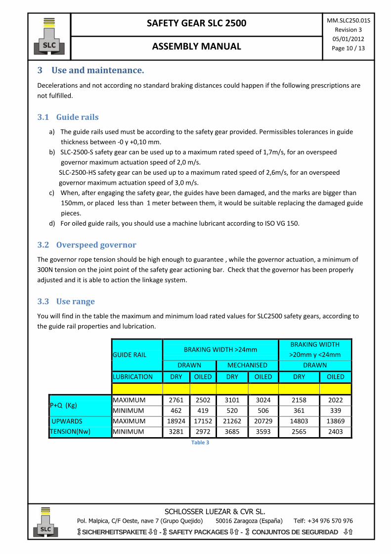
3.3 Use range
You will find in the table the maximum and minimum load rated values for SLC2500 safety gears, according to
the guide rail properties and lubrication.
GUIDE RAIL BRAKING WIDTH >24mm
BRAKING WIDTH
>20mm y <24mm
DRAWN MECHANISED DRAWN
LUBRICATION DRY OILED DRY OILED DRY OILED
P+Q (Kg) MAXIMUM 2761 2502 3101 3024 2158 2022
MINIMUM 462 419 520 506 361 339
UPWARDS
TENSION(Nw)
MAXIMUM 18924 17152 21262 20729 14803 13869
MINIMUM 3281 2972 3685 3593 2565 2403
Table 3

SAFETY GEAR SLC 2500 MM.SLC250.01S
Revision 3
05/01/2012
Page 11 / 13 ASSEMBLY MANUAL
SCHLOSSER LUEZAR & CVR SL. Pol. Malpica, C/F Oeste, nave 7 (Grupo Quejido) 50016 Zaragoza (España) Telf: +34 976 570 976
SICHERHEITSPAKETE - SAFETY PACKAGES - CONJUNTOS DE SEGURIDAD
3.4 Braking parts replacement.
Braking parts, shoes and roller, are able to afford FOUR actuations in free falling for each actuation sense, this
is more than minimum required by standards.
Nevertheless, after a real intervention of the safety in free fall (not the maintenance engagements) we advice
the braking parts replacement. In this situation, please contact Luezar-Eco S.L. or distributor, who will indicate
you the steps to follow.
When periodic testings, under the same load conditions for the first testing proof, if the braking distance is
less than double the distance for the first proof, replacement of the braking parts will not be necessary.
For a better control, maintenance manager should keep a register including the safety interventions, indicating
the serial number and actuations, even the parameters of actuation, including load, tripping speed, roller
marks and braking distance..
3.5 Maintenance
3.5.1 Cleaning
It’s very important verifying that any strange element in placed inside the safety gear, so the movil parts can
work properly.
The inside of the safety gear must be kept clean. No lubricant or other product must be used if it can influence
the safety behaviour
3.5.2 Corrosion
SLC-2500 safety gears are protected against corrosion anyway. Nevertheless, a periodic control must be made
in order to check that all the parts are fine, especially the movil parts (including the linkage rotation).
The periodicity of these controls must be established according to the parameters and climatology of the
installation.

SAFETY GEAR SLC 2500 MM.SLC250.01S
Revision 3
05/01/2012
Page 12 / 13 ASSEMBLY MANUAL
SCHLOSSER LUEZAR & CVR SL. Pol. Malpica, C/F Oeste, nave 7 (Grupo Quejido) 50016 Zaragoza (España) Telf: +34 976 570 976
SICHERHEITSPAKETE - SAFETY PACKAGES - CONJUNTOS DE SEGURIDAD
Annex I SLC-2500 safety gear dimensions

SAFETY GEAR SLC 2500 MM.SLC250.01S
Revision 3
05/01/2012
Page 13 / 13 ASSEMBLY MANUAL
SCHLOSSER LUEZAR & CVR SL. Pol. Malpica, C/F Oeste, nave 7 (Grupo Quejido) 50016 Zaragoza (España) Telf: +34 976 570 976
SICHERHEITSPAKETE - SAFETY PACKAGES - CONJUNTOS DE SEGURIDAD
Annex II Engagement and rest roller positions
The roller will reach the following positions when actuating:
The rest position regards to the roller position while the habitual lift working.
The other positions are the engagement positions: the maximum positions reached by the roller in upwards
and downwards engagement. When these positions are reached, the braking strength is constant.
Nevertheless, it can happen that in low load and speed conditions, the energy absorbed by the safety gear
while braking process till the total car stop is so small that the roller can’t reach these positions.
Safety gear acting downwards
Rest position
Safety gear acting upwards