MAKE BEFORE BREAK MANUAL BYPASS PANEL FOR UPS (BM*): …3).pdf · slc adapt slc cube 3+ slc twin...
20
SLC ADAPT SLC CUBE 3+ SLC TWIN PRO2 SLC TWIN PRO 33 SLC X-TRA MAKE BEFORE BREAK MANUAL BYPASS PANEL FOR UPS (BM*): USER'S MANUAL
Transcript of MAKE BEFORE BREAK MANUAL BYPASS PANEL FOR UPS (BM*): …3).pdf · slc adapt slc cube 3+ slc twin...
SLC ADAPTSLC CUBE 3+SLC TWIN PRO2SLC TWIN PRO 33SLC X-TRA
MAKE BEFORE BREAK MANUAL BYPASS PANEL FOR UPS (BM*):
USER'S MANUAL

2 SALICRU

3
General index
1. INTRODUCTION.1.1. ACknowLedgement LetteR.
2. INFORMATION FOR SAFETY.2.1. USIng thIS mAnUAL.
2.1.1. Conventions and used symbols.
2.2. AddItIonAL SAFetY notICeS.
3. QUALITY AND STANDARD GUARANTEE.3.1. deCLARAtIon oF the mAnAgement.
3.2. StAndARd.
3.3. envIRonment.
4. DESCRIPTION.4.1. tYpeS oF mAnUAL BYpASS pAneLS.
4.2. pRodUCt deFInItIon.
4.2.1. nomenclature.
5. INSTALLATION.5.1. to ConSIdeR In the InStALLAtIon.
5.2. eQUIpment ReCeptIon.
5.2.1. Unpacking, contents checking and inspection.
5.2.2. Storage.
5.2.3. Unpacking.
5.2.4. Relocation till the installation place.
5.2.5. Location.
5.3. ConneCtIon.
5.3.1. Connection of the power supply to the bypass panel. UpS input line (rectifier).
5.3.2. Connection of the power supply of the bypass panel. Static bypass line (type of panels -B only).
5.3.3. Connecting the UpS with the bypass panel.
5.3.4. Connection of the loads to the bypass panel.
5.3.5. Connection of the auxiliary contact of the UpS manual bypass, with the bypass panel (not available in twIn pRo 33 panels).
5.3.6. Connection of the auxiliary contact of the UpS output switch, with the bypass panel (available in CUBe3+ series only).
5.3.7. Systems with «n» equipments in parallel or redundant.
5.3.7.1. power connections.
5.3.7.2. Connection of the auxiliary contact of the manual bypass switch of each UpS, with the one in the bypass panel (not available in panels of twIn pRo 33 series).
5.3.7.3. Connection among the auxiliary contact of the output switch of each UpS, with the ones in the bypass panel (available in panels of CUBe3+ and X-tRA series).
6. START UP AND SHUTDOWN.6.1. ContRoLS BeFoRe the StARt Up.
6.2. opeRAtIon to ShIFt FRom «oUt oF SeRvICe» (UpS oR UpS’S to «oFF») to «noRmAL opeRAtIng» (LoAdS SUppLIed BY the UpS oR UpS’S).
6.2.1. manual bypass panel with one UpS only.
6.2.2. manual bypass panels with two or more UpS’s.
6.3. ShIFtIng FRom «noRmAL opeRAtIng» (LoAdS SUppLIed BY the UpS oR UpS’S) to «mAIntenAnCe opeRAtIng» (LoAdS SUppLIed thRoUgh the mAnUAL BYpASS).
6.3.1. manual bypass panels with one UpS only.
6.3.2. manual bypass panel with two or more UpS’s.
6.4. ShIFtIng FRom «mAIntenAnCe opeRAtIng» (LoAdS SUppLIed thRoUgh the mAnUAL BYpASS) to «noRmAL opeRAtIng» (LoAdS SUppLIed BY the UpS oR UpS’S).
6.4.1. manual bypass panels with one UpS only.
6.4.2. manual bypass panels with two or more UpS’s.
6.5. dAILY StARt Up/ShUtdown pRoCedURe oF the UpS oR UpS'S (InveRteR StARt Up / ShUtdown).
6.6. CompLete ShUtdown oF the pAneL-UpS Set.
6.6.1. manual bypass panel with one UpS only.
6.6.2. manual bypass panels with two or more UpS’s.
USER'S MANUAL

4 SALICRU
SALICRU
1. INTRODUCTION.
1.1. Acknowledgement letter.
we would like to thank you in advance for the trust you have placed in us by purchasing this product. Read this instruction manual carefully in order to be familiarized with its contents, because, as much as you know and understand the equipment the highest will be your satisfaction and safety levels and their features will be optimized too.
we remain at you entire disposal for any further information or any query you should wish to make.
Yours sincerely.
• the equipment here described can cause important physical damages due to wrong handling. this is why, the installation, maintenance and/or fixing of itself must be done by our staff or qualified personnel exclusively.
• Although we have made every effort to guarantee a com-plete and accurate information in this user’s manual, we are not responsible for any errors or omissions that may exist.
the images included in this document are mere illustrations and they could not represent the part of the equipment ex-actly, therefore they are not contractual. nevertheless, dif-ferences that could exist will be alleviated or solved with the correct labelling of the equipment.
• According to our policy of constant evolution, we reserve the right to modify the specifications, operating or described actions in this document without fore-warning.
• Any reproduction, copy or third party concession, modification or partial or in whole translations of this manual or document, in any format or media, is prohib-ited without the previous written authorization of our firm, being reserved the full and exclusive ownership right over it.

5
2.2. AddItIonAl SAFetY notIceS.
• In the point of view of the installation and electrical safety, bypass panels must be considered as transformers or power lines of distribution.
• As the equipment has protection against electrical shock of class I, it is essential to install the protective earth cable (con-nect the pe cable to the terminal ( )).
• the bypass panel must be installed by qualified per-sonnel and it can be used by trained personnel
only, just with help of this «User’s manual».
• It is important to meet the safety instructions stated in the own «User’s, installation and start manual of the UpS».
the instructions that you are reading are referred to the own manual bypass panel only, and they are complemen-tary to the «UpS user’s manual».
• the neutral regimes from the input to the output are iden-tical for the bypass panels «with no galvanic isolation». It is mandatory to keep the neutral regime the same, for both the bypass panel and the UpS.
• when a bypass panel has a galvanic isolation trans-former, as an option and fitted in by the factory or in-
stalled later on by the end user, either in the input or output of the equipment, protections against indirect contact (RCd) must be fitted in at the output of each isolation transformer, in order to avoid the electrical shock risk in the secondary winding (transformer output), because due to its own nature of iso-lating will avoid the tripping of the protections fitted in the primary winding of the transformer.
• As a reminder, all the installed isolation transformers or those ones supplied from factory, the output neutral (N) is connected to the pe ( ) through a cable bridge between the neutral and pe terminals (tt regime). In case, it is re-quired an isolated output neutral, this cable bridge must be removed (It regime), take all the cautions stated in the re-spective local and/or national low voltage regulations.
• In those installations with It neutral regime, the switches and circuit breaker protections must break the neUtRAL apart from the three phases.
2. INFORMATION FOR SAFETY.
2.1. USIng thIS mAnUAl.
the generic documentation of the equipment is supplied in digital format in a Cd-Rom and it includes among other docu-ments the own user’s manual of the system and the document ek266*08 concerning the «Safety instructions». Before doing any action in the equipment as regards to installation or start up, location change, setting or handling of any nature, read them carefully.
the purpose of the user’s manual is to provide the information concerning the safety and the explanations of the procedures to follow for the installation and operating of the equipment. Read them carefully and follow the stated steps in the established order. the identification of all parts linked with the connection and start up by means of labels with their functionality, is corre-lated in the instructions of this document, in order to make any operating easy and reliable.
It is mandatory the compliance with «Safety instruc-tions», being the legal responsible the end user as re-gards to its observance and application.
Finally, once the equipment is installed and in operation, it is rec-ommended to keep the documentation Cd-Rom in a safe place with easy access, for the future consults or doubts that could arise.
the following terms are used in the document indistinctly when referring to:
• «Bypass, panel, equipment, or unit».- to the manual by-pass panel.
• «System or set».- Set based on one or more UpS’s and the manual bypass panel.
• «T.S.S.».- technical Service & Support.
• «Client, fitter, operator or end user».- they are used indistinctly and extending to the fitter and/or operator, they will do the cor-responding actions, being able to revert the responsibility of doing the respective actions in the same person as they are acting on behalf of himself.
• In those installations with It neutral regime, the switches and circuit breaker protections must break the neUtRAL apart from the phase or phases.
2.1.1. conventions and used symbols.
Some symbols can be used and shown in the equipment and/or in the context of the user’s manual.
For more information concerning the «Safety instructions», see section 1.1.1 of document ek266*08.
USER'S MANUAL

6 SALICRU
3. QUALITY AND STANDARD GUARANTEE.
3.1. declArAtIon oF the mAnAgement.
our target is the client’s satisfaction, therefore this management has decided to establish a Quality and environmental policy, by means of installation a Quality and environmental management System that becomes us capable to comply the requirements de-manded by the standard ISO 9001 and ISO 14001 and by our Clients and concerned parts too.
Likewise, the enterprise management is committed with the development and improvement of the Quality and environ-mental management System, by means of:
• the communication to all the company about the impor-tance of satisfaction both in the client’s requirements and in the legal and regulations.
• the Quality and environmental policy diffusion and the fixa-tion of the Quality and environment targets.
• to carry out revisions by the management.
• to provide the needed resources.
3.2. StAndArd.
the Make Before Break Manual Bypass Panel product is designed, manufactured and commercialized in accordance with the standard EN ISO 9001 of Quality management Sys-tems and certified by SgS body. the marking shows the conformity to the eeC directive by means of the application of the following standards:
• 2014/35/EU. - Low voltage directive (Lvd).
• 2014/30/EU. - electromagnetic Compatibility (emC).
• 2011/65/EU. - Restriction of hazardous Substances in elec-trical and electronic equipment (RohS).
In case of any modification or intervention over the equip-ment by the end-user, the manufacturer is not responsible.
declaration of conformity Ce of the product is at the client disposal under previous request to our headquar-ters offices.
3.3. envIronment.
this product has been designed to respect the environment and manufactured in accordance with the ISO 14001 norm.
Equipment recycling at the end of its useful life:our company commits to use the services of authorised societies and according to the regulations, in order to treat the whole recov-ered product at the end of its useful life (contact your distributor).
Packaging:to recycle the packaging, follow the legal regulations in force, in accordance with the particular norm of the country where the equipment is installed.
7
4. DESCRIPTION.
• the manual bypass is a peripheral option to the UpS, which allows selecting the power supply source that feeds the loads, either from the UpS or directly from commercial elec-trical mains. If the UpS has an isolation transformer at its output or in the static bypass line, the manual bypass panel must incorporate it, in order to make euqal both neutral re-gimes.
the isolation transformer is an option, which provides gal-vanic isolation between the primary and secondary wind-ings, in such way that it attenuates the electrical noises and transients coming from mains largely, and also they are transferred to the secondary winding in minor extent.
• the type of the manual bypass panel is make before break, so it doesn’t break the power supply to the loads when doing the shifting, unless it is operated in different order of the established one.
• In case the panel incorporates the «Backfeed protection» contactor, its operating must be considered as automatic and it doesn’t require any attention unless any of the pro-tection fuses is blown. do not handle the fuse holder switch of the «Backfeed protection», unless it is needed to replace any of these protection parts.
• these instructions are generic for each one of the stated series in the nomenclature, regardless of the type of panel. omit those terminal connections and manoeuvring of the switches that your unit doesn’t have.
4.1. tYpeS oF mAnUAl BYpASS pAnelS.
• Structurally, there are two type of manual bypass panels according to the own structure of the UpS:
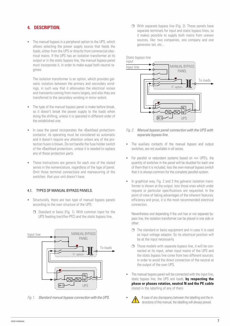
� Standard or basic (Fig. 1). with common input for the UpS feeding (rectifier-pFC) and the static bypass line.
UpS
mAnUAL BYpASS pAneL
to loads
Input line
It -option-
Fig. 1. Standard manual bypass connection with the UPS.
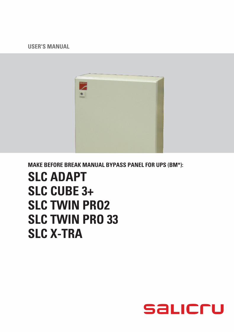
� with separate bypass line (Fig. 2). these panels have separate terminals for input and static bypass lines, so it makes possible to supply both mains from uneven sources, like: two companies, one company and one generator set, etc...
UpS
mAnUAL BYpASS pAneL
to loads
Input line
Static bypass line input
It -option-
Fig. 2. Manual bypass panel connection with the UPS with separate bypass line.
• the auxiliary contacts of the manual bypass and output switches, are not available in all series.
• For parallel or redundant systems based on «n» UpS’s, the quantity of switches in the panel will be doubled for each one of them that it is included, less the own manual bypass switch that it is always common for the complete parallel system.
• In graphical way, Fig. 2 and 3 the galvanic isolation trans-former is shown at the output, less those ones which under request or particular specifications are requested. In the point of view of taking advantages of the inherent features, efficiency and price, it is the most recommended electrical connection.
nevertheless and depending if the unit has or not separate by-pass line, the isolation transformer can be placed in one side or other:
� the standard or basic equipment and in case it is used as input voltage adaptor. So its electrical position will be at the input necessarily.
� those models with separate bypass line, it will be con-nected at its input, when input mains of the UpS and the static bypass line come from two different sources; in order to avoid the direct connection of the neutral at the output of the own UpS.
• the manual bypass panel will be connected with the input line, static bypass line, the UpS and loads, by respecting the phase or phases rotation, neutral N and the PE cable stated in the labelling of any of them.
• If case of any discrepancy between the labelling and the in-structions of this manual, the labelling will always prevail.
USER'S MANUAL

8 SALICRU
4.2. prodUct deFInItIon.
4.2.1. nomenclature.
3 Bm-CUBe+-p-40-LBt-2/2 ee602322-1.
ee* particular specifications of the client.
2 First character of the output voltage for single phase or phase to phase voltage for three phase. omit for 230v or 3x400v.
2 First character of the input voltage for single phase or phase to phase voltage for three phase. omit for 230v or 3x400v.
t Isolation transformer. Located at the output, less those ones with separate bypass line which comes from a different source of the UpS input mains.
B equipment with separate bypass line.
L Single phase in/out configuration.m Single in / three out configuration.n three in / single out configuration. three in/out configuration.
40 power in kvA.
p manoeuvring mechanisms by means of circuit breakers. In-distinctly of SLC CUBe3 + parallel UpS systems, the output mechanism is always a disconnect switch, never a circuit breaker.
AdAptCUBe3+ X-tRA Series of the equipment, which is destined the panel.twIn pRo2twIn pRo 33
m make before break.
B manual bypass.C exclusive protection panel with no manual bypass.
3 Quantity of equipments in parallel. omitted for single units.

9
5. INSTALLATION.
• Read and respect any information as regards to Safety, which is described in section 2 of this document. to ob-
viate any of the described indications, can cause serious or very serious injuries to persons with direct contact or accidents in the vicinity, as well as failures in the own bypass panel, equipment or equipments and/or loads connected to the system.
• Check that the data in the nameplate is the required one by the installation.
• A wrong connection or manoeuvring, can cause failures in the panel, equipment or equipments and/or loads connected to the system. Read the instructions of this manual carefully and follow the stated steps in the established order.
• the connection will only be done, if the switches of the equipment or equipments are in off position and
with no mains (switch or switches of the power supply line or lines of the panel must be turned «off»).
• Any connection of the bypass panel described in this docu-ment will be done according to both the labelling of the unit and the single line diagrams. Structurally, there are six types of panels, regardless of their possible configurations (L, m, n,...):
� generic manual bypass panel for a standard UpS (Fig. 3).
� generic manual bypass panel for a standard UpS with separate bypass line (Fig. 4).
� manual bypass panel for «n» standard parallel or re-dundant UpS’s (Fig. 5). For UpS of CUBe3+, twIn pRo2 and twIn pRo 33 series.
� manual bypass panel for «n» standard parallel or redun-dant UpS’s (Fig. 6), for UpS of AdApt and X-tRA series.
� manual bypass panel for «n» parallel or redundant UpS’s with separate bypass line (Fig. 7), for UpS of CUBe3+, twIn pRo2 and twIn pRo 33 series.
� manual bypass panel for «n» parallel or redundant UpS’s with separate bypass line (Fig. 8), for UpS of AdApt and X-tRA series.
Apart from the stated structures, there are several aspects re-garding the connection of the control wiring of each UpS series, which are explained later on in this section.
• the reproduced illustrations in this document are mere examples, and they are intended to show the lineal order layout of the manoeuvring mechanisms, without taking ac-count of the physical format of them due to the power rate of the equipment. Another factor to consider, it is that all figures show the circuit breaker switch option “p” of the manoeuvring mechanisms.
• According to the model of the panel, the enclosure can differ (plastic, metallic case or metallic cabinet), so the aspect of them could be affected, but the order would be the same.
• depending on the power of the bypass panel and requested version, the manoeuvring mechanisms can differ in quantity (parallel systems), quantity of poles (depending on the configura-tion), format, size and type (switch or circuit breaker), but they will always be identified through the labelling.
pay attention to the stated steps to change the oper-ating mode, attending the labelling over the manoeu-
vring mechanisms.
• the manual bypass panel version with separate bypass line (-B), has additional parts of connection and control, which can only be found in this type of panel. omit, any reference to them in the standard or basic version.
5.1. to conSIder In the InStAllAtIon.
• these instructions are generic for any manual bypass panel of this series. omit those not available terminal connections.
• All connections in the panel are done through terminals. nevertheless in some models and due to their high power or current, the connection of the cables can be done directly to the copper rods of the own switches.
• Regarding the main pe cable and earth bonding cable con-nections, the panels usually have two points located on op-posite ends, generally by threaded stud.
• In the documentation supplied in the Cd-Rom to-gether with each UpS, it is available the information
regarding the «Recommended installation» for each one of the input and output configurations. In this document, it is shown the circuit diagrams, the size of the protections and minimum cross cable section of the cables that join the equipment with the panel according to the nominal oper-ating voltage. All figures are calculated for a maximum cable length of 30 m between the distribution panel, equipment and loads.
� For higher lengths correct the cross cable sections in order to avoid dropping voltages, by respecting the Regulations or Standards corresponding to the country.
� In the same documentation and for each configuration, it is available the information for «n» units in parallel, as well as the features of the own «Backfeed protection».
It is mandatory to respect all the indications stated in the UpS user’s manual as regards to the «Backfeed pro-tection», considering the possibility of having or not the separate bypass line and the corresponding actions to make in each case.
• In parallel systems, the length and cross cable sec-tion, which goes from the panel till each UpS and vice
versa, will be the same for all of them with no exception.
• Cross cable section must be always considered according to the size of the own terminals of the switches, in order to clamp them properly and to give an optimal contact be-tween both parts.
USER'S MANUAL
10 SALICRU
• the data in the nameplate of the equipment shows the nominal currents only as the safety standard en-IeC 62040-1 states. the overload conditions are considered as a nonpermanent and exceptional operating mode.
• If peripheral elements are going to be added at the input, output or bypass of the UpS or parallel systems like transformers or auto-transformers, the stated currents in the nameplates of those parts must be considered in order to use the appropriate cross cable section, by respecting the Local and/or national Low voltage elec-trotechnical Regulation.
• once the installation is finished, do not forget that the by-pass panel is connected to a UpS or UpS set. Starting from the concept that the UpS is an electrical generator, the end user will take the needed cautions against the direct or in-direct contact.
5.2. eQUIpment receptIon.
5.2.1. Unpacking, contents checking and inspection.
• to unpack it, see section 5.2.3.
• when receiving the equipment, check that no damages have occurred during transport (impacts, falls, ...) and the features of the equipment corresponds with the stated in the purchase order, so it is recommended to unpack the equipment for an initial visual inspection.
• In case of observing damage, make the appropriate claims to your supplier or in lack of it to our firm.
do not start up any equipment when external dam-ages have been observed.
• Also check that the data in the nameplate sticked in the packaging and the equipment, correspond to the one stated in the purchase order, so it will be needed to unpack it (see section 5.2.3). otherwise, make the nonconformity as soon as possible, quoting the serial number of the equipment and the reference in the delivery note.
• Check the contents in the packaging:
� the own bypass panel.
� the user’s manual in electronic format (Cd-Rom).
� those panels supplied in wall mounting format, the ac-cessories to fix it to the wall (bolts and nuts and sup-ports) and the whole layout diagram.
• once the reception is finished, it is better to pack the panel again till its commissioning, in order to protect it against mechanical impacts, dust, dirt, etc...
5.2.2. Storage.
• the equipment storage, will be done in a dry and cool place, protected from rain, dust and water jets or chemical agents. It is advisable to keep the equipment inside its original packaging
because it has been designed to guarantee the maximum pro-tection during transport and storage.
5.2.3. Unpacking.
• the equipment unpacking can have wooden pallet, card-board or wooden box depending on the case, expanded pol-ystyrene corners (epS) or polyethylene foam (epe), plastic bag and polyethylene bands. All materials are recyclable; so if they are going to be disposed, do it in accordance with the regulations in force. It is recommended to keep the packaging, in case it was needed in future.
• proceed to the equipment unpacking.
to do it, cut the bands of the cardboard enclosure and/or the sealing adhesive tape. those panels with wooden packaging, open it with the appropriate means available.
Remove the equipment out from the cardboard or wooden en-closure.
5.2.4. relocation till the installation place.
• If the reception area is far from the installation place, it is recommended to move the equipment by means of a pallet jack or the most suitable transport means, keeping in mind the remoteness between both points.
If the distance is important, it is recommended to move the equipment completely packed till the installation place and later on unpack it.
5.2.5. location.
• Locate the equipment paying attention to the indications and recommendations stated in the safety instructions ek266*08.
• the equipment will be located close to the UpS or parallel system based on «n» equipments.
• the manual bypass panels are supplied in wall mounting cases, less those exception cases assembled in floor standing cabinets.
For the first option, make the wholes in the wall according to the diagram, supplied in paper together with the fixing accessories, and proceed to fix it.
5.3. connectIon.
• wall mounting cases are supplied with the cable glands al-ready assembled, of the suitable size for the foreseen cables.
• depending on the input, bypass and/or output typology (single phase or three phase), the quantity of terminals of each strip can differ. Connect the corresponding cables ac-cording to each case, by respecting the phase (R) or phases (R-S-t) and neutral (n) rotation.

11
• when discrepancies between the labelling of the equipment and the instructions of this user’s manual
exist, the labelling in the equipment will always prevail.
• the references in bold between brackets, which are shown in the different points of this section, correspond to the UpS elements identified in their own user’s manual. For more infor-mation consult that document.
5.3.1. connection of the power supply to the bypass panel. UpS input line (rectifier).
• It is mandatory to connect the main protection earth cable to the terminal labelled as ( ), being sure that
it is done before supplying voltage to the bypass panel.
• Connect the power supply cables of the input line to tto the termi-nals labelled as «InpUt LIne» of the bypass panel, by respecting the phase (R) or phases (R-S-t) and neutral (n) rotation, stated in the equipment labelling and this manual.
It is essential to have neutral (n).
5.3.2. connection of the power supply of the bypass panel. Static bypass line (type of panels -B only).
• It is mandatory to connect the main protection earth cable to the terminal labelled as ( ), being sure that
it is done before supplying voltage to the bypass panel.
• Connect the power supply cables of the bypass line to the by-pass panel, to the terminals labelled as «StAtIC BYpASS InpUt LIne», by respecting the phase (R) or phases (R-S-t) and neutral (n) rotation, stated in the equipment labelling and this manual.
It is essential to have neutral (n).
5.3.3. connecting the UpS with the bypass panel.
• Connect a cable bundle between the terminal strip of the bypass panel labelled as «UpS InpUt» and the UpS input terminals labelled as «InpUt», by respecting the phase (R) or phases (R-S-t) and neutral (n) rotation, stated in the equipment labelling and this manual.
• those equipments with separate static bypass line, connect a cable bundle between the terminal strip of the bypass panel labelled as «StAtIC BYpASS InpUt» and the UpS input terminals labelled as «StAtIC BYpASS», by respecting the phase (R) or phases (R-S-t) and neutral (n) rotation, stated in the equipment labelling and this manual.
• Connect the cable bundle between the terminal strip of the bypass panel labelled as «UpS oUtpUt» and the UpS output terminals labelled as «oUtpUt», by respecting the phase (R) or phases (R-S-t) and neutral (n) rotation, stated in the equipment labelling and this manual.
5.3.4. connection of the loads to the bypass panel.
• It is mandatory to connect the main protection earth cable to the terminal labelled as ( ), being sure that
it is done before supplying voltage to the bypass panel.
• Connect the loads to the terminal strip of the bypass panel labelled as «LoAdS oUtpUt», by respecting the phase (R) or phases (R-S-t) and neutral (n) rotation, stated in the equipment labelling and this manual.
5.3.5. connection of the auxiliary contact of the UpS manual bypass, with the bypass panel (not available in twIn pro 33 panels).
• By means of control wiring (minimum 1 mm2 and maximum 2,5 mm2 ), it is mandatory to connect the
terminal strip labelled as «BYpASS AUXILIARY ContACt» of the UpS with the ones in the bypass panel. these signal ter-minals are the extension of the normally opened auxiliary contact, of its respective internal manual bypass.
the UpS auxiliary terminals are labelled as follows, de-pending on the product series:
� AdApt, pins 1 and 2 of (JP5).
� CUBe3+, two terminal strip (X51).
� X-tRA, terminals (MBY1) and (MBY2).
� twIn pRo2, two terminal strip (EMBS control port).
• this connection is a safety lock against wrong manoeuvring, which otherwise would involve damages in the UpS and/or supplied loads, because it switches the inverter «off» when turning any of the manual bypass switches «on».
5.3.6. connection of the auxiliary contact of the UpS output switch, with the bypass panel (available in cUBe3+ series only).
• the UpS output switch has a normally opened auxiliary con-tact, with a cable as bridge (PT) which is closing the circuit in the terminal strip (X45).
• Remove it and by means of control wiring (minimum 1 mm2 and maximum 2,5 mm2 ) connect the terminal strip labelled as «oUtpUt AUXILIARY ContACt» of the UpS (X45) with the ones in the bypass panel. these signal terminals are the extension of the normally opened auxiliary contact, of its re-spective internal output switch.
the purpose of this connection is to trigger an alarm in the control panel due to the trip or turning any of the output switches to «off» (both UpS and/or panel).
USER'S MANUAL

12 SALICRU
INPU
T LI
NE
LOADS OUPUT
SAI
InpUtoUtpUtAux. cont. outputAux. cont. manual bypass
UPS INPUT
MANUAL BYPASS
UPS OUTPUT
UPS
INPU
T
UPS
OU
TPU
T
(*) A
ux. c
ont.
man
ual B
ypas
s (1)
outp
ut (2
)
MANUAL BYPASS PANEL
(*) Aux. cont.(*) Aux. cont., available in manual bypass panel for UPS's:
SLC ADAPT SLC CUBE 3+ SLC TWIN PRO2 SLC TWIN PRO 33 SLC X-TRA(1) YeS YeS YeS - YeS(2) - YeS - - -
Fig. 3. Generic manual bypass panel for standard UPS.
INPU
T LI
NE
STA
TIC
BYP
ASS
IN
PUT
LIN
E
LOADS OUPUT
UPS
OU
TPU
T
UPS
INPU
T
UPS
STA
TIC
BYP
ASS
STATIC BYPASS
MANUAL BYPASS
UPS OUTPUT
(*) A
ux. c
ont.
man
ual B
ypas
s (1)
outp
ut (2
)
UPS INPUT
InpUtStAtIC BYpASSoUtpUtAux. cont. outputAux. cont. manual bypass
MANUAL BYPASS PANEL
SAI
(*) Aux. cont.(*) Aux. cont., available in manual bypass panel for UPS's:
SLC ADAPT SLC CUBE 3+ SLC X-TRA(1) YeS YeS YeS(2) - YeS -
Fig. 4. Generic manual bypass panel for a UPS with separate bypass line.
5.3.7.2. Connection of the auxiliary contact of the manual bypass switch of each UpS, with the one in the bypass panel (not available in panels of twIn pRo 33 series).
• By means of control wiring (minimum 1 mm2 and maximum 2,5 mm2 ), it is mandatory to connect the
terminal strip labelled as «BYpASS AUXILIARY ContACt» of the UpS with the ones in the bypass panel. these signal ter-minals are the extension of the normally opened auxiliary contact, of its respective internal manual bypass.
5.3.7. Systems with «n» equipments in parallel or redundant.
5.3.7.1. power connections.
• make the connections stated in sections 5.3.1 and 5.3.2.
• make and repeat for each equipment that makes the system, the connections stated in section 5.3.3.

13
the UpS auxiliary terminals are labelled as follows, de-pending on the product series:
� AdApt, pins 1 and 2 of (JP5).
� CUBe3+, two terminal strip (X51).
� X-tRA, terminals (MBY1) and (MBY2).
� twIn pRo2, two terminal strip (EMBS control port).
• the way of connecting the control cables of the UpS’s with the panel will differ depending on the UpS series, as well as the quantity of available terminals in the control strip:
� CUBe3+.
make the parallel connection among the auxiliary con-tacts of the manual bypass switch of each equipment and the ones in the bypass panel (see Fig. 5 and 7).
� AdApt, twIn pRo2 and X-tRA.
the manual bypass switch of the panel will have as many extended auxiliary contacts of the control strip as quantity of UpS’s to connect in parallel (see Fig. 6 and 8).Connect the terminal strip of the panel with each UpS of the parallel system respectively. Never joint these connections, because each UpS has internal different grounds.
As it has been stated previously, this connection is a safety lock against wrong manoeuvring.
5.3.7.3. Connection among the auxiliary contact of the output switch of each UpS, with the ones in the bypass panel (available in panels of CUBe3+ and X-tRA series).
• the output switch of each UpS has a normally opened auxiliary contact , with a cable as a bridge mode (PT), which closes the circuit in the terminal strip (X45) in CUBe3+ series or in terminal strip (OAC-1) and (OAC-2) in X-tRA series.
• Remove it and by means of control wiring (minimum 1 mm2 and maximum 2,5 mm2 ) connect the terminal strip labelled as «oUtpUt AUXILIARY ContACt» of the UpS (X45) or (OAC-1) and (OAC-2) with the ones in the bypass panel, keeping in mind the correlative order of each one of them.
So, the «oUtpUt AUXILIARY ContACt» terminals (X45) or (OAC-1) and (OAC-2) of UpS nr 1 to the auxiliary terminal strip «oUtpUt 1 UpS», the terminals «oUtpUt AUXILIARY ContACt» (X45) or (OAC-1) and (OAC-2) of UpS nr 2 to the auxiliary terminal strip «oUtpUt 2 UpS» and so on, according to the quantity of equipments that makes the system.
INPU
T LI
NE
LOADS OUPUT
MANUAL BYPASS
(*) A
ux. c
ont.
man
ual B
ypas
s (1)
UpS
1 ou
tput
(2)
••
•Up
S «n
» out
put (2
)
UPS
1 IN
PUT
InpUtoUtpUtAux. cont. outputAux. cont. manual bypass
MANUAL BYPASS PANEL
SAI «N»
UPS
«N
» IN
PUT
UPS
1 O
UTP
UT
UPS
«N
» O
UTP
UT
•••
SAI 1
UPS
1 IN
PUT
UPS
«N
» IN
PUT
InpUtoUtpUtAux. cont. outputAux. cont. manual bypass
•••
•••
UPS
«N» O
UTPU
T
UPS
1 OUT
PUT
•••
•••
(*) Aux. cont.(*) Aux. cont., available in manual bypass panel for UPS's:
SLC CUBE 3+ SLC TWIN PRO 33(1) YeS -(2) YeS -
Fig. 5. Manual bypass panel for «n» standard UPS’s in parallel or redundant, of CUBE3+ and TWIN PRO 33 series .
USER'S MANUAL

14 SALICRU
INPU
T LI
NE
LOADS OUPUT
MANUAL BYPASS
Aux
. con
t.
UpS
1 man
ual B
ypas
s (1)
•••
UpS
«n» m
anua
l Byp
ass (1)
UpS
1 out
put (2)
•••
UpS
«n» o
utpu
t (2)
UPS
1 IN
PUT
InpUtoUtpUtAux. cont. outputAux. cont. manual bypass
MANUAL BYPASS PANEL
SAI «N»
UPS
«N
» IN
PUT
UPS
1 O
UTP
UT
UPS
«N
» O
UTP
UT
•••
SAI 1
UPS
1 IN
PUT
UPS
«N
» IN
PUT
InpUtoUtpUtAux. cont. outputAux. cont. manual bypass
•••
•••
UPS
«N» O
UTPU
T
UPS
1 OU
TPUT
•••
•••
(*) Aux. cont.(*) Aux. cont., available in manual bypass panel for UPS's:
SLC ADAPT SLC TWIN PRO2 SLC X-TRA(1) YeS YeS YeS(2) - - YeS
Fig. 6. Manual bypass panel for «n» standard UPS’s in parallel or redundant from ADAPT, TWIN PRO2 and X-TRA series.
INPU
T LI
NE
LOADS OUPUT
MANUAL BYPASS
Aux
. con
t.m
anua
l Byp
ass( 1
)
UpS
1 ou
tput
(2)
••
•Up
S «n
» out
put (2)
UPS
1 IN
PUT
InpUtStAtIC BYpASSoUtpUtAux. cont. outputAux. cont. manual bypass
MANUAL BYPASS PANEL
SAI «N»
UPS
«N
» IN
PUT
UPS
1 O
UTP
UT
UPS
«N
» O
UTP
UT
•••
SAI 1
UPS
1 IN
PUT
UPS
«N
» IN
PUT
InpUtStAtIC BYpASSoUtpUtAux. cont. outputAux. cont. manual bypass
STA
TIC
BYP
ASS
IN
PUT
LIN
E
UPS
«N» S
TATI
C BY
PASS
UPS
1 STA
TIC
BYPA
SS
••• •••
•••
UPS
«N» O
UTPU
T
UPS
1 OUT
PUT
•••
UPS
1 ST
ATIC
BYP
ASS
UPS
«N» S
TATI
C BY
PASS
•••
•••
(*) Aux. cont.(*) Aux. cont., available in manual bypass panel for UPS's:
SLC CUBE 3+(1) YeS(2) YeS
Fig. 7. Manual bypass panel for «n» UPS’s with separate bypass line in parallel or redundant from CUBE3+ series.

15
INPU
T LI
NE
LOADS OUPUT
InpUtStAtIC BYpASSoUtpUtAux. cont. outputAux. cont. manual bypass
MANUAL BYPASS PANEL
SAI «N»U
PS 1
OU
TPU
T
UPS
«N
» O
UTP
UT
SAI 1
UPS
1 IN
PUT
UPS
«N
» IN
PUT
InpUtStAtIC BYpASSoUtpUtAux. cont. outputAux. cont. manual bypass
•••
••••••
MANUAL BYPASS
Aux
. con
t.
UpS
1 man
ual B
ypas
s (1)
•••
UpS
«n» m
anua
l Byp
ass (1)
UpS
1 out
put (2)
•••
UpS
«n» o
utpu
t (2)
STA
TIC
BYP
ASS
IN
PUT
LIN
E
UPS
«N» S
TATI
C BY
PASS
UPS
1 STA
TIC
BYPA
SS
•••
UPS
«N» O
UTPU
T
UPS
1 OU
TPUT
•••
UPS
1 ST
ATIC
BYP
ASS
UPS
«N» S
TATI
C BY
PASS
•••
UPS
1 IN
PUT
UPS
«N
» IN
PUT
•••
(*) Aux. cont.(*) Aux. cont., available in manual bypass panel for UPS's:
SLC ADAPT SLC X-TRA(1) YeS YeS(2) - YeS
Fig. 8. Manual bypass panel for «n» UPS’s with separate bypass line in parallel or redundant from ADAPT and X-TRA series.
USER'S MANUAL

16 SALICRU
6. START UP AND SHUTDOWN.
• these instructions are generic for any manual bypass panel of this series, parallel and redundant equipments included. omit those manoeuvring of the switches that your unit doesn’t have.
• the references in bold between brackets, which are shown in the different points of this section, correspond to the UpS elements identified in their own user’s manual. For more infor-mation consult that document.
• the shown illustrations in this section are mere examples and they are with four poles switches of dIn rail type, but in practice they can differ in one or more aspects like: type of panel configu-ration, format, size or protection type. nevertheless, in any case the order will not be different from the stated in them.
Also, in the manual bypass panels in parallel or redundant equipments, the illustrations do not match with any preset system, so they are generic for any panel regardless of the quantity of equipments in parallel or redundant that belong to.
6.1. controlS BeFore the StArt Up.
• Check that all connections have done properly, by re-specting the labelling of the equipment and the instructions in section «InStALLAtIon». If phase or phases and neu-tral rotation is not respected, important damages can be caused to the panel, UpS or UpS’s and/or connected loads.
• In order to avoid bad electrical contacts, check the connec-tions screws are firmly tighten.
• Check all switches coming from the power supply which feeds the bypass panel, the own ones in the panel (see Fig. 9 or 10 depending on the case) and the ones in the UpS or UpS’s are turned «off».
UPS INPUT STATIC BYPASS MANUAL BYPASS UPS OUTPUT
Off Off Off + Off
Fig. 9. Position of the manual bypass switches «Out of service» (with one UPS only).
UPS 1 INPUT UPS 1 STATIC BYPASS MANUAL BYPASS UPS 1 OUTPUT
Off Off Off + Off
•••
UPS N INPUT
Off
•••
UPS N STATIC BYPASS
Off
UPS N OUTPUT
Off
•••
Fig. 10. Position of the manual bypass switches «Out of service» (with several UPS’s).
• make sure that all the loads are shutdown (start up switches turned «off»).
• proceed in the established order of this document. Any wrong manoeuvring over the stated switches of the by-
pass panel, or the ones in the UpS or UpS’s, can cause a break or short-circuits in the power supply to the loads, with the unin-tended and unexpected consequences for any part of the set.
• In the installation section, for single and parallel equipments, it is stated the need of connecting the auxiliary contact of the manual bypass with the one in the manual bypass panel. thanks to this auxiliary safety contact, in case of wrong or different manoeuvring than the stated in this section, it is avoided to overlap the inverter output with the UpS input power supply.
For any change in the operating mode, respect the steps stated in the instructions of this section strictly, and in par-ticular, for the twIn pRo 33 series, which do not have this auxiliary contact, but they have the needed protections, in order to make the steps in the established order.
Before starting the equipment up, check that the manual bypass switch of the equipment or equip-
ments and the one in the manual bypass panel are in the same position (UpS and off or BYpASS and on).
6.2. operAtIon to ShIFt From «oUt oF ServIce» (UpS or UpS’S to «oFF») to «normAl operAtIng» (loAdS SUpplIed BY the UpS or UpS’S).
• turn the external protections of the bypass panel «on» (RCd and/or circuit breaker switches), they will supply energy to the termi-nals labelled as «InpUt LIne».
• In panels with separate bypass line (-B), turn the external protections of the bypass panel «on» (RCd and/or circuit breaker switches) «on», they will supply energy to the terminals labelled as «StAtIC BYpASS InpUt LIne».
6.2.1. manual bypass panel with one UpS only.
• turn the «UpS InpUt» and «UpS oUtpUt» switches of the bypass panel to «on». In case of including the separate by-pass line (-B), turn the «StAtIC BYpASS» switch of the bypass panel «on» too. In the illustration of Fig. 11, it is shown the position of switches once the manoeuvring has been done.

17
• Start up the UpS according to the procedure stated in the «User’s, installation and start up manual» of the equipment. the bypass panel supplies voltage to the terminals labelled as «LoAdS oUtpUt».
UPS INPUT STATIC BYPASS MANUAL BYPASS UPS OUTPUT
On On Off + On
Fig. 11. Position of the bypass panel switches in «Normal operating» (with one UPS only).
• Start up the loads, they are supplied from the output termi-nals of the panel, through the UpS.
6.2.2. manual bypass panels with two or more UpS’s.
UPS 1 INPUT UPS 1 STATIC BYPASS MANUAL BYPASS UPS 1 OUTPUT
On On Off + On
•••
UPS N INPUT
On
•••
UPS N STATIC BYPASS
On
UPS N OUTPUT
On
•••
Fig. 12. Position of the bypass panel switches in «Normal operating» (with several UPS’s).
• turn the bypass panel switches «UpS 1 InpUt» to «UpS n InpUt» and «UpS 1 oUtpUt» to «UpS n oUtpUt» to «on». If the separate bypass line is also available (-B), turn the «UpS 1 StAtIC BYpASS» to «UpS n StAtIC BYpASS» switches from panel to «on» too. In the illustration of Fig. 12, it is shown the position of switches once the manoeu-vring has been done.
• Start up all the UpS’s according to the procedure stated in the «User’s, installation and start up manual» of the equip-ment. the bypass panel supplies voltage to the terminals labelled as «LoAdS oUtpUt».
• Start up the loads, they are supplied from the output termi-nals of the panel, through the UpS’s.
6.3. ShIFtIng From «normAl operAtIng» (loAdS SUpplIed BY the UpS or UpS’S) to «mAIntenAnce operAtIng» (loAdS SUpplIed throUgh the mAnUAl BYpASS).
6.3.1. manual bypass panels with one UpS only.
• put the UpS on bypass (inverter «Off»), according to the procedure stated in the «User’s, installation and start up manual» of the UpS.
It is essential to shutdown the inverter of the UpS before proceeding, otherwise a short-circuit at its
output will be made with unexpected and unintended out-comes for any part of the set (UpS, panel and loads).
• Remove the mechanical lock from the switch labelled as «mAnUAL BYpASS» in the bypass panel and turn it «on». keep the mechanical lock in a safe place, because it will have to put it back, once the maintenance or fixing tasks have been finished.
• manual bypass panels with isolation transformer, the loads will be supplied with a clean and/or attenuated voltage from electrical noises.
• turn «UpS InpUt» and «UpS oUtpUt» switches from bypass panel to «off». In case the separate bypass line (-B) was avail-able, turn the «StAtIC BYpASS» switch of the bypass panel to «off» too. In the illustration of Fig. 13, it is shown the position of the switches once the manoeuvring has been finished.
• Loads are supplied by mains directly through the manual bypass panel and UpS is completely shutdown, so it is ready to be serviced for a preventive maintenance, fixing or replacement for another equipment with the same speci-fications.
UPS INPUT STATIC BYPASS MANUAL BYPASS UPS OUTPUT
Off Off On + Off
Fig. 13. Position of the bypass panel switches in «mainte-nance operating» (with one UPS only).
• In case of faulty UpS, it can also be removed and sent to the factory for its fixing. nevertheless it is better not do it, because loads would be connected to mains directly and so exposed to mains fluctuations.
even, if this alternative is going to be done, it is manda-tory to remove any cable bundle connected to the
panel, which has at its opposite end the cables bare from isolation, resulting in a risk of electrocution or short-circuit in case of turning on any of the panel switches.
USER'S MANUAL
18 SALICRU
6.3.2. manual bypass panel with two or more UpS’s.
• put all the UpS’s on bypass (inverters «Off»), according to the procedure stated in the «User’s, installation and start up manual» of the UpS.
It is essential to shutdown the inverters of the UpS’s before proceeding, otherwise a short-circuit at
its output will be made with unexpected and unintended out-comes for any part of the set (UpS’s, panel and loads).
• Remove the mechanical lock from the switch labelled as «mAnUAL BYpASS» in the bypass panel and turn it «on». keep the mechanical lock in a safe place, because it will have to put it back, once the maintenance or fixing tasks have been finished.
• manual bypass panels with isolation transformer, the loads will be supplied with a clean and/or attenuated voltage from electrical noises.
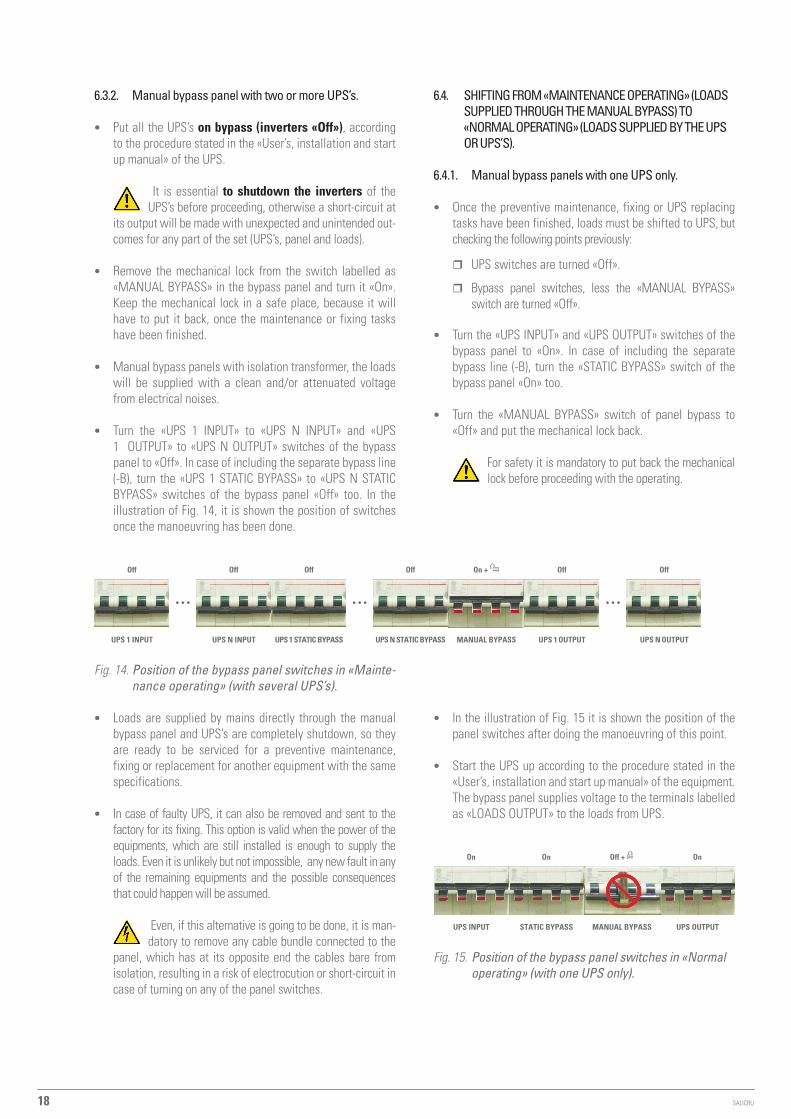
• turn the «UpS 1 InpUt» to «UpS n InpUt» and «UpS 1 oUtpUt» to «UpS n oUtpUt» switches of the bypass panel to «off». In case of including the separate bypass line (-B), turn the «UpS 1 StAtIC BYpASS» to «UpS n StAtIC BYpASS» switches of the bypass panel «off» too. In the illustration of Fig. 14, it is shown the position of switches once the manoeuvring has been done.
UPS 1 INPUT UPS 1 STATIC BYPASS MANUAL BYPASS UPS 1 OUTPUT
Off Off On + Off
•••
UPS N INPUT
Off
•••
UPS N STATIC BYPASS
Off
UPS N OUTPUT
Off
•••
Fig. 14. Position of the bypass panel switches in «Mainte-nance operating» (with several UPS’s).
• Loads are supplied by mains directly through the manual bypass panel and UpS’s are completely shutdown, so they are ready to be serviced for a preventive maintenance, fixing or replacement for another equipment with the same specifications.
• In case of faulty UpS, it can also be removed and sent to the factory for its fixing. this option is valid when the power of the equipments, which are still installed is enough to supply the loads. even it is unlikely but not impossible, any new fault in any of the remaining equipments and the possible consequences that could happen will be assumed.
even, if this alternative is going to be done, it is man-datory to remove any cable bundle connected to the
panel, which has at its opposite end the cables bare from isolation, resulting in a risk of electrocution or short-circuit in case of turning on any of the panel switches.
6.4. ShIFtIng From «mAIntenAnce operAtIng» (loAdS SUpplIed throUgh the mAnUAl BYpASS) to «normAl operAtIng» (loAdS SUpplIed BY the UpS or UpS’S).
6.4.1. manual bypass panels with one UpS only.
• once the preventive maintenance, fixing or UpS replacing tasks have been finished, loads must be shifted to UpS, but checking the following points previously:
� UpS switches are turned «off».
� Bypass panel switches, less the «mAnUAL BYpASS» switch are turned «off».
• turn the «UpS InpUt» and «UpS oUtpUt» switches of the bypass panel to «on». In case of including the separate bypass line (-B), turn the «StAtIC BYpASS» switch of the bypass panel «on» too.
• turn the «mAnUAL BYpASS» switch of panel bypass to «off» and put the mechanical lock back.
For safety it is mandatory to put back the mechanical lock before proceeding with the operating.
• In the illustration of Fig. 15 it is shown the position of the panel switches after doing the manoeuvring of this point.
• Start the UpS up according to the procedure stated in the «User’s, installation and start up manual» of the equipment. the bypass panel supplies voltage to the terminals labelled as «LoAdS oUtpUt» to the loads from UpS.
UPS INPUT STATIC BYPASS MANUAL BYPASS UPS OUTPUT
On On Off + On
Fig. 15. Position of the bypass panel switches in «Normal operating» (with one UPS only).

19
6.4.2. manual bypass panels with two or more UpS’s.
• once the preventive maintenance, fixing or UpS or UpS’s replacing tasks have been finished, loads must be shifted to them, but checking the following points previously:
� UpS’s switches are turned «off».
� Bypass panel switches, less the «mAnUAL BYpASS» switch are turned «off».
• turn the «UpS 1 InpUt» to «UpS n InpUt» and «UpS 1 oUtpUt» to «UpS n oUtpUt» switches of the bypass panel to «on». In case of including the separate bypass line (-B), turn the «UpS 1 StAtIC BYpASS» to «UpS n StAtIC BY-pASS» switches of the bypass panel «on» too.
• turn the «mAnUAL BYpASS» switch of panel bypass to «off» and put the mechanical lock back.
For safety it is mandatory to put back the mechanical lock before proceeding with the operating.
UPS 1 INPUT UPS 1 STATIC BYPASS MANUAL BYPASS UPS 1 OUTPUT
On On Off + On
•••
UPS N INPUT
On
•••
UPS N STATIC BYPASS
On
UPS N OUTPUT
On
•••
Fig. 16. Position of the bypass panel switches in «Normal operating» (with one UPS only).
• In the illustration of Fig. 16 it is shown the position of the panel switches after doing the manoeuvring of this point
• Start the UpS’s up according to the procedure stated in the «User’s, installation and start up manual» of the equipment. the bypass panel supplies voltage to the terminals labelled as «LoAdS oUtpUt» to the loads from UpS’s.
6.5. dAIlY StArt Up/ShUtdown procedUre oF the UpS or UpS'S (Inverter StArt Up / ShUtdown).
• In case of need it, see the procedure stated in the «User’s, installation and start up manual» of the equipment.
6.6. complete ShUtdown oF the pAnel-UpS Set.
6.6.1. manual bypass panel with one UpS only.
• Shutdown the load or loads.
• Shutdown the UpS according to the procedure stated in the «User’s, installation and start up manual» of the equipment.
• turn the «UpS InpUt» and «UpS oUtpUt» switches of the bypass panel to «off». In case of including the separate by-pass line (-B), turn the «StAtIC BYpASS» switch of the bypass panel «off» too. In the illustration of Fig. 9, it is shown the position of switches once the manoeuvring has been done.
• turn «off» the external protections of the bypass panel (RCd and/or circuit breaker switches), which are supplying the energy to the terminals labelled as «InpUt LIne».
• those panels with separate static bypass line (-B), turn «off» the external protections of the bypass panel (RCd and/or circuit breaker switches), which are supplying the energy to the terminals labelled as «StAtIC BYpASS InpUt LIne».
• the set is out of service completely and with no power supply.
6.6.2. manual bypass panels with two or more UpS’s.
• Shutdown the load or loads.
• Shutdown the UpS’s according to the procedure stated in the «User’s, installation and start up manual» of the equip-ment.
• turn the «UpS 1 InpUt» to «UpS n InpUt» and «UpS 1 oUtpUt» to «UpS n oUtpUt» switches of the bypass panel to «off». In case of including the separate bypass line (-B), turn the «UpS 1 StAtIC BYpASS» to «UpS n StAtIC BYpASS» switches of the bypass panel «off» too. In the illustration of Fig. 10, it is shown the position of switches once the manoeuvring has been done.
• turn «off» the external protections of the bypass panel (RCd and/or circuit breaker switches), which are supplying the energy to the terminals labelled as «InpUt LIne».
• those panels with separate static bypass line (-B), turn «off» the external protections of the bypass panel (RCd and/or circuit breaker switches), which are supplying the energy to the terminals labelled as «StAtIC BYpASS InpUt LIne».
• the set is out of service completely and with no power supply.
USER'S MANUAL

Avda. de la Serra 100
08460 palautordera
BARCELONA
tel. +34 93 848 24 00
Fax +34 93 848 22 05
SALICRU.COM
www.linkedin.com/company/salicru
@salicru_SA
Product Range
Uninterruptible power Supplies (UpS)
lighting Flow dimmer-Stabilisers
dc power Systems
Static Inverters
photovoltaic Inverters
voltage stabilisers
the technical Service and Support (t.S.S.) network, com-
mercial network and warranty information are available in
website:
www.salicru.com
REF. eL043d01 REV. d CODE 401*