Thermal Wave II - Interlink Supply
97
Thermal Wave® II Service and Operation Manual BLUELINE Equipment Co. LLC 2604 Liberator Dr., Prescott, AZ 86301 1-928-445-3030
Transcript of Thermal Wave II - Interlink Supply
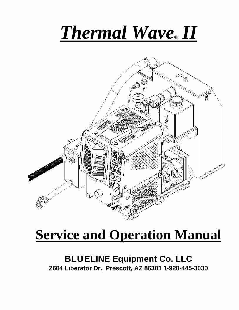
Thermal Wave® II
Service and Operation Manual
BLUELINE Equipment Co. LLC 2604 Liberator Dr., Prescott, AZ 86301 1-928-445-3030
BLUELINE THERMALWAVE II I
Congratulations on your purchase of the THERMALWAVE II® truck mount cleaning unit. This instruction/parts manual is a guide for operating and servicing your BLUELINE truck mount unit. Proper operation and service are necessary to ensure the outstanding performance of this unit. When properly maintained, your truck mount will have a long and trouble-free life. The following service methods outlined in this manual are detailed in a manner that operation and servicing may be performed properly and safely. Because service levels vary due to the skill of the mechanic, tools and parts availability, ensure that prior to attempting any repair, you are familiar with this equipment and have the proper tools. Any questions regarding the operation, service, or repair of this unit should be directed to your nearest BLUELINE dealer. The headings WARNING and CAUTION are utilized to warn you that steps must be taken to prevent personal injury or damage to the equipment. Please make sure that you have read and understand these instructions entirely before proceeding with the operation of this unit. THIS UNIT MUST BE INSTALLED BY THE DEALER THAT YOU PURCHASED IT FROM IN ACCORDANCE WITH THE BLUELINE INSTALLATION PROCEDURES. PLEASE ENSURE THAT THE WARRANTY CARD IS FILLED OUT BY THE DISTRIBUTOR THAT YOU PURCHASED THIS UNIT FROM AND RETURNED TO BLUELINE.
Record your units serial number here for future reference or if you should need to contact the factory in the future for any reason. S/N: This service and operations manual is written specifically for BLUELINE THERMALWAVE II® Truck Mount Cleaning units manufactured by: BLUELINE EQUIPMENT LLC 2604 Liberator Drive Prescott, AZ 86301 USA The information contained in this document is subject to change without notice and does not represent a commitment on the part of BLUELINE EQUIPMENT LLC. All rights reserved. Copyright 2005 by BLUELINE EQUIPMENT LLC. No part of this work may be used or reproduced in any form or means without the express written consent and permission of BLUELINE EQUIPMENT LLC. Published by BLUELINE EQUIPMENT LLC. First printing: December 2005 Printed in USA THERMALWAVE II® MANUAL PART# 49-021
December-05
BLUELINE THERMALWAVE II II
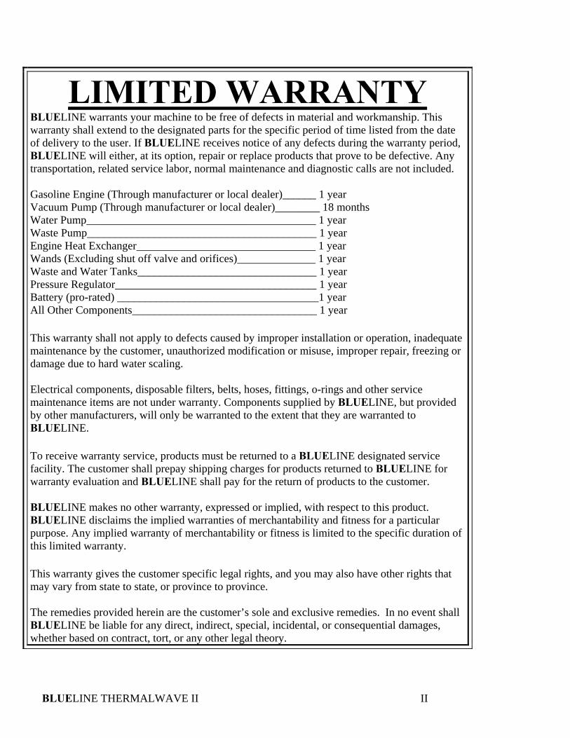
LIMITED WARRANTY BLUELINE warrants your machine to be free of defects in material and workmanship. This warranty shall extend to the designated parts for the specific period of time listed from the date of delivery to the user. If BLUELINE receives notice of any defects during the warranty period, BLUELINE will either, at its option, repair or replace products that prove to be defective. Any transportation, related service labor, normal maintenance and diagnostic calls are not included. Gasoline Engine (Through manufacturer or local dealer)______ 1 year Vacuum Pump (Through manufacturer or local dealer)________ 18 months Water Pump_________________________________________ 1 year Waste Pump_________________________________________ 1 year Engine Heat Exchanger________________________________ 1 year Wands (Excluding shut off valve and orifices)______________ 1 year Waste and Water Tanks________________________________ 1 year Pressure Regulator____________________________________ 1 year Battery (pro-rated) ____________________________________1 year All Other Components_________________________________ 1 year This warranty shall not apply to defects caused by improper installation or operation, inadequate maintenance by the customer, unauthorized modification or misuse, improper repair, freezing or damage due to hard water scaling. Electrical components, disposable filters, belts, hoses, fittings, o-rings and other service maintenance items are not under warranty. Components supplied by BLUELINE, but provided by other manufacturers, will only be warranted to the extent that they are warranted to BLUELINE. To receive warranty service, products must be returned to a BLUELINE designated service facility. The customer shall prepay shipping charges for products returned to BLUELINE for warranty evaluation and BLUELINE shall pay for the return of products to the customer. BLUELINE makes no other warranty, expressed or implied, with respect to this product. BLUELINE disclaims the implied warranties of merchantability and fitness for a particular purpose. Any implied warranty of merchantability or fitness is limited to the specific duration of this limited warranty. This warranty gives the customer specific legal rights, and you may also have other rights that may vary from state to state, or province to province. The remedies provided herein are the customer’s sole and exclusive remedies. In no event shall BLUELINE be liable for any direct, indirect, special, incidental, or consequential damages, whether based on contract, tort, or any other legal theory.
BLUELINE THERMALWAVE II III
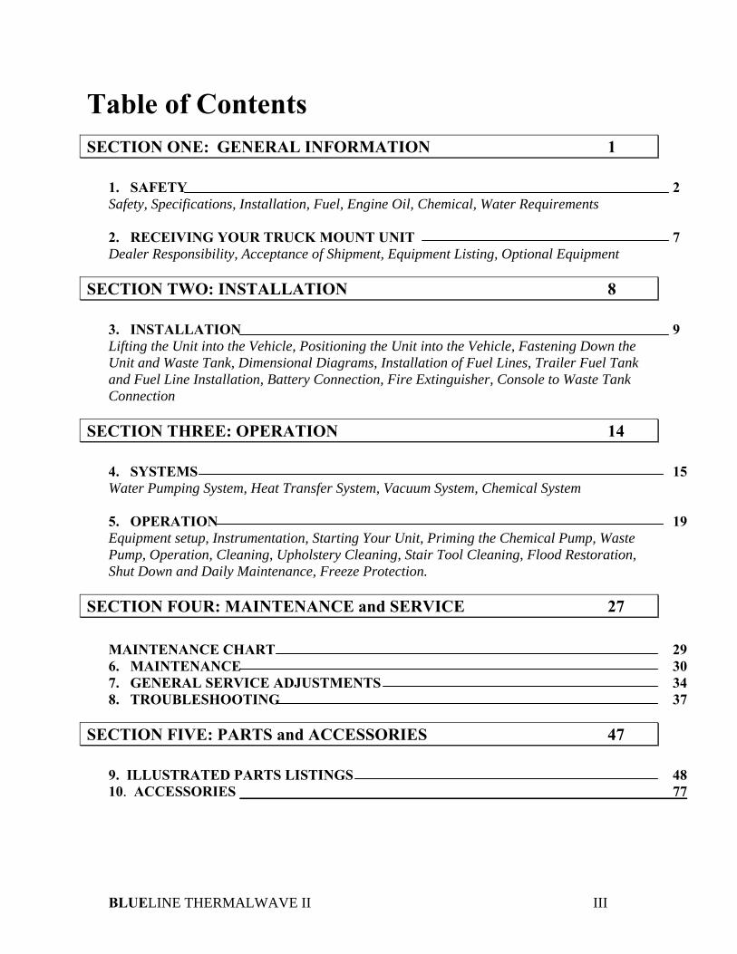
Table of Contents SECTION ONE: GENERAL INFORMATION 1
1. SAFETY 2 Safety, Specifications, Installation, Fuel, Engine Oil, Chemical, Water Requirements 2. RECEIVING YOUR TRUCK MOUNT UNIT 7 Dealer Responsibility, Acceptance of Shipment, Equipment Listing, Optional Equipment
SECTION TWO: INSTALLATION 8 3. INSTALLATION 9 Lifting the Unit into the Vehicle, Positioning the Unit into the Vehicle, Fastening Down the Unit and Waste Tank, Dimensional Diagrams, Installation of Fuel Lines, Trailer Fuel Tank and Fuel Line Installation, Battery Connection, Fire Extinguisher, Console to Waste Tank Connection
SECTION THREE: OPERATION 14 4. SYSTEMS 15 Water Pumping System, Heat Transfer System, Vacuum System, Chemical System 5. OPERATION 19 Equipment setup, Instrumentation, Starting Your Unit, Priming the Chemical Pump, Waste Pump, Operation, Cleaning, Upholstery Cleaning, Stair Tool Cleaning, Flood Restoration, Shut Down and Daily Maintenance, Freeze Protection.
SECTION FOUR: MAINTENANCE and SERVICE 27
MAINTENANCE CHART 29 6. MAINTENANCE 30 7. GENERAL SERVICE ADJUSTMENTS 34 8. TROUBLESHOOTING 37
SECTION FIVE: PARTS and ACCESSORIES 47
9. ILLUSTRATED PARTS LISTINGS 48 10. ACCESSORIES 77

BLUELINE THERMALWAVE II 1
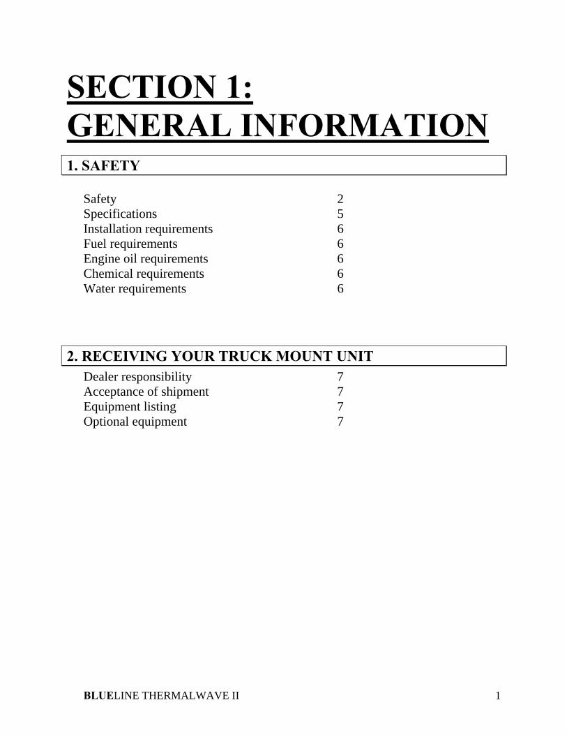
SECTION 1: GENERAL INFORMATION 1. SAFETY
Safety 2 Specifications 5 Installation requirements 6 Fuel requirements 6 Engine oil requirements 6 Chemical requirements 6 Water requirements 6
2. RECEIVING YOUR TRUCK MOUNT UNIT Dealer responsibility 7 Acceptance of shipment 7 Equipment listing 7 Optional equipment 7
SECTION 1
BLUELINE THERMALWAVE II 2
1. SAFETY
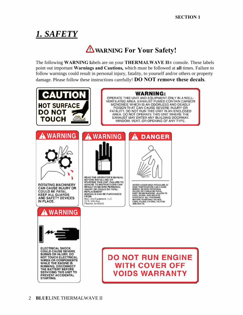
For Your Safety! The following WARNING labels are on your THERMALWAVE II® console. These labels point out important Warnings and Cautions, which must be followed at all times. Failure to follow warnings could result in personal injury, fatality, to yourself and/or others or property damage. Please follow these instructions carefully! DO NOT remove these decals.
SECTION 1
BLUELINE THERMALWAVE II 3
! 1. Read the operator's manual before starting this unit. Failure to adhere to instructions could result in severe personal injury or could be fatal.
2. Operate this unit and equipment only in a well- ventilated area. Exhaust fumes contain carbon monoxide, which is an odorless and deadly poison that can cause severe injury or death. DO NOT run this unit in an enclosed area. DO NOT operate this unit where the exhaust may enter a building doorway, window, vent or other opening.
3. Gasoline is extremely flammable and its vapors can explode if ignited. Store gasoline only in approved containers, in well-ventilated, unoccupied buildings and away from sparks or flames. Never carry gasoline or any flammable materials in the vehicle. Fumes could accumulate inside of the vehicle and ignite, causing an explosion.
4. This unit must be operated with the vehicle doors open in order to ensure adequate ventilation to the engine. 5. DO NOT operate unit if gasoline is spilled. Do not turn ignition switch until the gasoline has been cleaned up. Never use gasoline for cleaning purposes.
6. DO NOT place hands, feet, hair, clothing or any body parts near rotating or moving parts. Rotating machinery can cause severe injury or death. 7. NEVER operate this unit without belt and safety guards. High speed moving parts, such as belts and pulleys, should be avoided while the unit is running. Severe injury, fatality or damage may result.
8. NEVER service this unit while it is running. High speed mechanical parts as well as high temperature components may result in injury or severed limbs. 9. Engine components will be extremely hot from operation. To prevent severe burns, DO NOT touch these areas while the unit is running or shortly after the unit is shut off. 10. DO NOT touch any part of the exhaust system while the system is running or for 20 minutes after the unit is shut off. Severe burns could result. 11. Water under high pressure at high temperature can cause burns, severe personal injury, or fatality. Shut down unit, allow to cool down and relieve system of all pressure before removing caps, valves, plugs, fittings, filters or hardware. 12. NEVER leave the vehicle engine running while the unit is in operation. 13. Battery acid contains sulfuric acid. To prevent acid burns, avoid contact with skin, eyes and clothing. Batteries also produce explosive hydrogen gases while charging. To prevent fire or explosion, charge batteries only in a well ventilated area. Keep sparks, open flames, as well as other sources of ignition away from battery at all times. Remove all jewelry prior to servicing batteries. Keep batteries out of the reach of children. Before disconnecting the negative (-) ground cable, ensure that all switches are in the off position. If on, a spark could occur at the ground connection terminal which could cause an explosion if hydrogen gas or gasoline vapors are present. ALWAYS disconnect the negative (-) terminal first. 14. DO NOT smoke around the machine. Gas fumes could accumulate and ignite. Battery
SECTION 1
BLUELINE THERMALWAVE II 4
gases are extremely flammable. This will prevent possible explosions. 15. DO NOT damage the vehicle in any way during the installation. When routing fuel lines DO NOT configure the hose in any locations where the hose or vehicle could be damaged. Avoid contact with moving parts, areas of high temperature, brake lines, fuel lines, catalytic converters, exhaust pipes, mufflers or sharp objects. 16. NEVER cut or splice any of the vehicle fuel lines during fuel line installation. This will result in fuel leaks and potentially dangerous conditions. Use only the provided fuel hose for fuel lines. When going through the vehicle floor with fuel lines, always utilize bulkhead adaptors. This will prevent fuel leaks and ensure that hoses are not punctured by vehicle vibration abrasion. 17. DO NOT exceed your vehicles weight limit. The console with waste tank and accessories weighs approximately 1420 pounds. Make certain that the vehicle has the correct axle rating. This will prevent unsafe or hazardous driving conditions. 18. High back seats are required for all vehicles that units are to be installed for head and neck protection. Metal partitions between the seats and equipment are strongly recommended. 19. DO NOT operate this unit without the water supply on and attached. The water pump and other vital components could be seriously damaged if the unit is operated dry. This unit is equipped with a low pressure shut down switch, which should NOT be bypassed. 20. Always keep your vehicle clean and orderly. Wands, tools and accessories must be securely stowed while driving the vehicle.
21. All high-pressure hoses must be rated at 3000 PSI and have a heat rating of 250 degrees F. Thermoplastic hoses do not meet this criteria and should never be used. Severe burns and other injuries could result if hoses do not meet these requirements. 22. Ensure that you have received proper training from the distributor that you purchased the unit from prior to operation. 23. This unit produces high pressure and high temperatures. Improper use could result in serious injury. 24. DO NOT modify this unit in any manner. Any modification could result in serious injury or fatality. 25. California Proposition 65 Warning: Engine exhaust from this product contains chemicals known by the State of California to cause cancer, birth defects, or other reproductive harm.
SECTION 1
BLUELINE THERMALWAVE II 5
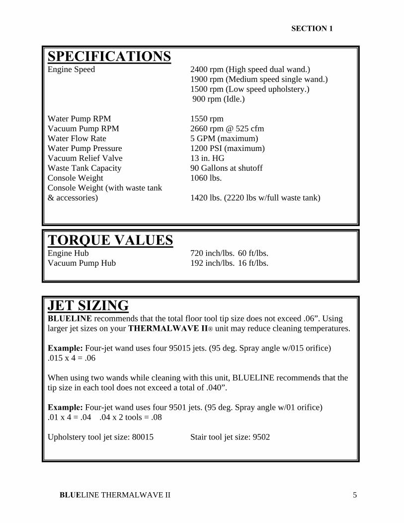
SPECIFICATIONS Engine Speed 2400 rpm (High speed dual wand.) 1900 rpm (Medium speed single wand.)
1500 rpm (Low speed upholstery.) 900 rpm (Idle.)
Water Pump RPM 1550 rpm Vacuum Pump RPM 2660 rpm @ 525 cfm Water Flow Rate 5 GPM (maximum) Water Pump Pressure 1200 PSI (maximum) Vacuum Relief Valve 13 in. HG Waste Tank Capacity 90 Gallons at shutoff Console Weight 1060 lbs. Console Weight (with waste tank & accessories) 1420 lbs. (2220 lbs w/full waste tank)
TORQUE VALUES Engine Hub 720 inch/lbs. 60 ft/lbs. Vacuum Pump Hub 192 inch/lbs. 16 ft/lbs.
JET SIZING BLUELINE recommends that the total floor tool tip size does not exceed .06”. Using larger jet sizes on your THERMALWAVE II® unit may reduce cleaning temperatures. Example: Four-jet wand uses four 95015 jets. (95 deg. Spray angle w/015 orifice) .015 x 4 = .06 When using two wands while cleaning with this unit, BLUELINE recommends that the tip size in each tool does not exceed a total of .040”. Example: Four-jet wand uses four 9501 jets. (95 deg. Spray angle w/01 orifice) .01 x 4 = .04 .04 x 2 tools = .08 Upholstery tool jet size: 80015 Stair tool jet size: 9502
SECTION 1
BLUELINE THERMALWAVE II 6
INSTALLATION REQUIREMENTS Prior to beginning the installation, read the ENTIRE “Installation” section of this manual. Since the THERMALWAVE II® truck mount unit weighs (with waste tank and accessories) 1420 lbs., please adhere to the following recommendations prior to installing the unit. 1. The unit should NOT be installed in any motor vehicle of less than 3/4 ton capacity.
! The console and waste tank with accessories must NOT exceed the vehicles axle weight limit. 2. If mounting the unit in a trailer, ensure that the trailer is rated for the total weight of the unit and trailer. Electric or hydraulic brakes must be provided, and strict compliance with all State and Federal laws must be maintained. 3. If mounting in a trailer, the THERMALWAVE II® console must be positioned so that it balances properly with respect to the trailer axle. Ten percent (10%) of the units total overall weight (w/o accessories or water) should be on the tongue. 4. The vehicle tires must have a load rating in excess of the combined unit and vehicle weight. 5. BLUELINE does not recommend using any type of flooring materials that absorb water. This condition will result in rust and corrosion of the vehicle floor. 6. Insulation under rubber mats should be removed prior to installation of the unit. FUEL REQUIREMENTS Use unleaded fuel ONLY. NEVER use any gasoline additives. Use only fresh, clean unleaded gasoline intended for normal automotive use. DO NOT use high-octane gasoline with this unit.
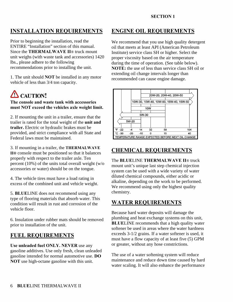
ENGINE OIL REQUIREMENTS We recommend that you use high quality detergent oil that meets at least API (American Petroleum Institute) service class SH or higher. Select the proper viscosity based on the air temperature during the time of operation. (See table below). NOTE: the use of less than service class SH oil or extending oil change intervals longer than recommended can cause engine damage.
CHEMICAL REQUIREMENTS The BLUELINE THERMALWAVE II® truck mount unit’s unique last step chemical injection system can be used with a wide variety of water diluted chemical compounds, either acidic or alkaline, depending on the work to be performed. We recommend using only the highest quality chemistry. WATER REQUIREMENTS Because hard water deposits will damage the plumbing and heat exchange systems on this unit, BLUELINE recommends that a high quality water softener be used in areas where the water hardness exceeds 3-1/2 grains. If a water softener is used, it must have a flow capacity of at least five (5) GPM or greater, without any hose constrictions. The use of a water softening system will reduce maintenance and reduce down time caused by hard water scaling. It will also enhance the performance
SECTION 1
BLUELINE THERMALWAVE II 7
of cleaning chemicals, which will result in greater efficiency in lower concentrations.
2. RECEIVING YOUR TRUCK MOUNT UNIT DEALER RESPONSIBILITY THE BLUELINE DEALER THAT YOU PURCHASED THIS TRUCK MOUNT CLEANING UNIT FROM IS RESPONSIBLE FOR THE PROPER INSTALLATION OF THIS MACHINE. THE DEALER IS ALSO RESPONSIBLE FOR THE PROPER INITIAL TRAINING OF YOUR OPERATORS AND MAINTENANCE PERSONNEL. ACCEPTANCE OF SHIPMENT Your THERMALWAVE II® truck mount cleaning unit was thoroughly tested, checked and inspected in its entirety prior to leaving our manufacturing facility. When receiving your unit, please make the following acceptance check: 1. The unit should not show any signs of damage. If there is damage, notify the common carrier immediately. 2. Carefully check your equipment and packing list. The standard BLUELINE THERMALWAVE II® unit should arrive with the following items as well as any optional accessories: EQUIPMENT LISTING A. BLUELINE THERMALWAVE II® console. B. Operation and Service manual. C. Installation mounting plates and bolt down kit. D. Hose clamps for vacuum and fuel hoses. E. Carpet wand. F. Waste tank with shutoff switch and filters.
H. Pre-Filter box and stainless steel strainer basket. I. 150 ft. of 1/4 in. high pressure solution hose with quick connects. J. 150 ft. of 2 in. vacuum hose K. 2 vacuum hose connector. L. 50 ft. water supply hose with quick connect. OPTIONAL EQUIPMENT
A. Additional lengths of vacuum hose Part # 18-003 B. Additional vacuum hose connectors Part # 21-003 C. Additional high-pressure solution hoses Part # 18-000 (With shutoff valve Part # 18-001) D. Automatic waste pump kit Part # 68-003 E. Demand pump system Part # 68-002 F. KIT, FUEL HOOKUP CHEVY 97 TO 2002. FI Part # 69-003FI G. KIT, FUEL HOOKUP CHEVY/DODGE FI Part # 69-004FI H. KIT, FUEL HOOKUP FORD FI Part # 69-005 FI I. KIT, FUEL HOOKUP 2003 CHEVY FI Part #69-018FI J. KIT, 2004 TF ADAPTER CHEVY Part # 69-032 K. KIT, 2004 TF FUEL INJ. CHEVY Part # 69-033 L. ADAPTOR, 2004 FORD FUEL Part # 69-041 M. ADAPTOR, 2004 FUEL INJ. FORD Part #69-041FI
BLUELINE THERMALWAVE II 8
SECTION 2: INSTALLATION 3 INSTALLATION
Lifting the unit into the vehicle 9 Positioning the unit into the vehicle 9 Fastening down the unit and waste tank 9 Dimensional diagrams 10 Installation of fuel lines 12 Trailer fuel tank and fuel line installation 12 Battery Connection 12 Fire extinguisher 12 Console to waste tank connection 13
SECTION 2
BLUELINE THERMALWAVE II 9
3. INSTALLATION
!!! This unit must be bolted to the floor of the vehicle by an authorized BLUELINE DISTRIBUTOR. LIFTING THE UNIT INTO THE VEHICLE The BLUELINE THERMALWAVE II® weighs approximately 1420 lbs., a forklift is necessary to place the unit into the vehicle. Place the forks into the forklift slots from the front of the unit and make CERTAIN that the forks are spread to the maximum width of the unit. POSITIONING THE UNIT INTO THE VEHICLE Vehicles vary in size and openings. Owners have different preferences on where in the vehicle they want their units positioned. BLUELINE strongly recommends a side door installation for the THERMALWAVE II®. We DO NOT recommend a rear door installation. 1.Ensure that enough space is provided to assure adequate engine ventilation as well as room for service and maintenance. 2. The complete unit with waste tank and accessories MUST NOT exceed the vehicle’s axle weight limit. 3. NEVER position the console closer than 12 inches from the bottom rear of the driver and passenger seats.
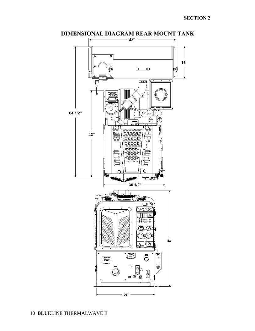
FASTENING DOWN THE UNIT AND WASTE TANK
!!! Prior to drilling any holes in the vehicle floor, ensure that while drilling, you will not damage the fuel tank, fuel lines, or any other vital components, which could affect the safety and or operation of the vehicle. A. The console and waste tank mounting holes will serve as a template. Drill six (6) 13/32 in. diameter holes for the console and six (6) 13/32 in. diameter holes for the waste tank. B. Using the provided mounting hardware kit:
1. Insert six (6) 3/8-16 x 2 ½ in. hex head cap screws with flat washers through the THERMALWAVE II® console mounting holes, and six (6) 3/8-16 x 2 in. hex head cap screws with flat washers through the waste tank mounting holes.
2. Install the provided mounting plates
underneath the vehicle floor.
3. Screw the provided 3/8-16 hex head lock nuts on to the mounting bolts and tighten until the console and waste tank are firmly attached to the vehicle floor.
SECTION 2
BLUELINE THERMALWAVE II 10
DIMENSIONAL DIAGRAM REAR MOUNT TANK
SECTION 2
BLUELINE THERMALWAVE II 11
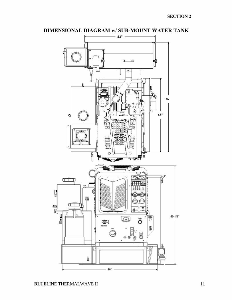
DIMENSIONAL DIAGRAM w/ SUB-MOUNT WATER TANK
SECTION 2
BLUELINE THERMALWAVE II 12
INSTALLATION OF FUEL LINES
!!! READ THESE INSTRUCTIONS IN THEIR ENTIRETY PRIOR TO PROCEEDING.
! The Vehicle fuel lines should NOT be spliced under ANY circumstances. Severe injury or fatality could result. DO NOT damage the vehicle in any way during the installation. When routing fuel lines DO NOT configure the hoses in any location where the hoses or vehicle could be damaged. Avoid contact with moving parts, areas of high temperature, brake lines, fuel lines, catalytic converters, exhaust pipes, mufflers or sharp objects. TRAILER FUEL TANK AND FUEL LINE INSTALLATION The following are recommendations for trailer installations: A. Strict compliance with all federal and state laws must be maintained. B. Use only fuel tanks that are manufactured specifically for gasoline, have proper vented filling caps, and outlet connections that are the same size as the inlet and return connections on the unit. C. DO NOT install fuel tanks inside any type of enclosed trailer or vehicle.
! NEVER carry gasoline or flammable materials in an enclosed trailer or vehicle. NEVER store any type of flammable material in an enclosed trailer or vehicle.
D. Always mount fuel tanks where they will be protected from any vehicle collision. E. When installing fuel lines from the fuel tank to the unit, use the proper size fuel line. BATTERY CONNECTION
! Explosive gases, Dangerous gases! Batteries contain sulfuric acid. To prevent acid burns, avoid contact with skin, eyes and clothing. Batteries also produce explosive hydrogen gases while charging. To prevent fire or explosion, charge batteries only in a well ventilated area. Keep sparks, open flames, as well as any other sources of ignition away from batteries at all times. Remove all jewelry prior to servicing batteries. Keep batteries out of the reach of children. Before disconnecting the negative (-) ground cable, ensure that all switches are in the OFF position. If ON, a spark could occur at the ground connection terminal, which could cause an explosion if hydrogen gas or gasoline vapors are present. ALWAYS disconnect the negative (-) terminal first. A. Attach the red positive (+) battery cable from the starter solenoid on the console to the positive (+) terminal on the battery and tighten down the nut. B. Attach the black negative (-) battery cable from the ground on the console to the negative (-) terminal on the battery and tighten down the nut. FIRE EXTINGUISHER BLUELINE , and many government agencies, recommend that a fire extinguisher rated for A, B, and C type fires be installed into any commercial vehicle.
SECTION 2
BLUELINE THERMALWAVE II 13
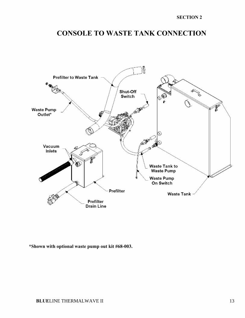
CONSOLE TO WASTE TANK CONNECTION
*Shown with optional waste pump out kit #68-003.
BLUELINE THERMALWAVE II 14
SECTION 3: OPERATION 4. SYSTEMS Water pumping system 15 Heat transfer system 16 Vacuum system 17 Chemical pumping system 18 5. OPERATION Preparation 19 Starting the unit 21 Priming the chemical pump 22 Automatic waste pump 22 Operation 22 Cleaning 23 Upholstery cleaning 23 Stair tool cleaning 23 Flood restoration/extraction 23 Shut down and daily maintenance 23 Freeze protection 24
SECTION 3
BLUELINE THERMALWAVE II 15
4. SYSTEMS NOTE: Read and understand this section of the manual entirely before proceeding. This portion of the manual divides the unit up into systems and describes how each system works. Prior to proceeding into the operations and maintenance sections of this manual it is recommended that you acquire a basic understanding of how the unit functions. WATER PUMPING SYSTEM See figures 3-1 and 5-10. Cold water enters the console through the water inlet connection located on the lower right corner of the right lower front panel. The water then flows to the water box through a float valve, which shuts off the water when the water box is full. Water then flows through a strainer in the water box to the water pump. The water pump is plumbed to a nitrogen charged accumulator, which helps reduce pressure pulsations. The water pump assembly also includes a high-pressure and a low-pressure shutdown switch. These switches will shut down the unit if the water pressure exceeds 1200 PSI or drops below 50 PSI for more than 5 seconds. Simultaneously, water is then pumped to the pressure regulator assembly, which provides and maintains the desired pressure setting. Water then flows from the pressure regulator through the heli-coil engine coolant heat exchanger and into the blower exhaust heat exchanger, where it is super-heated by the blower exhaust. The water then flows through the check valve manifold that contains a Y-strainer and a check valve. At this point, the chemical injection takes place.
The hot solution mixture of water and chemicals then flows through the solution outlet manifold to the cleaning tool. Temperature is controlled with the temperature control valve. Water temperature is maintained by mixing cooler water from the water box with heated water from the heli-coil and the blower exhaust heat exchanger.
SECTION 3
BLUELINE THERMALWAVE II 16
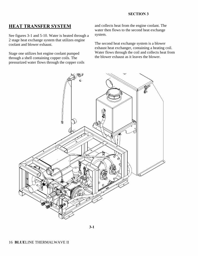
HEAT TRANSFER SYSTEM See figures 3-1 and 5-10. Water is heated through a 2 stage heat exchange system that utilizes engine coolant and blower exhaust. Stage one utilizes hot engine coolant pumped through a shell containing copper coils. The pressurized water flows through the copper coils
and collects heat from the engine coolant. The water then flows to the second heat exchange system. The second heat exchange system is a blower exhaust heat exchanger, containing a heating coil. Water flows through the coil and collects heat from the blower exhaust as it leaves the blower.
3-1
SECTION 3
BLUELINE THERMALWAVE II 17
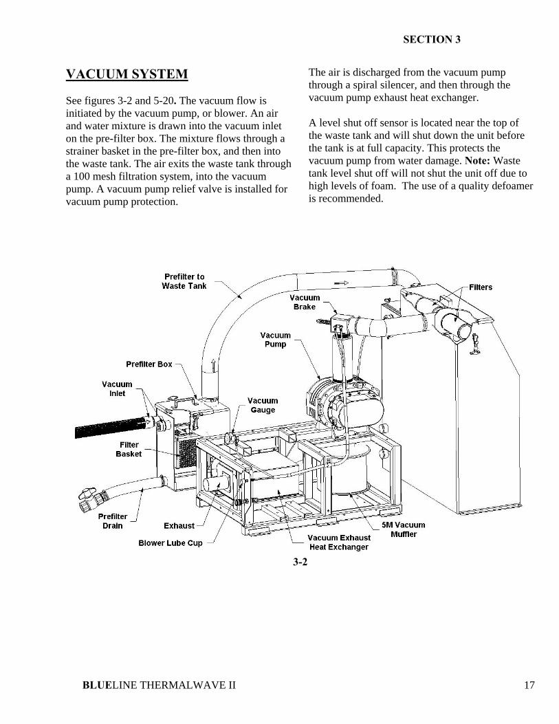
VACUUM SYSTEM See figures 3-2 and 5-20. The vacuum flow is initiated by the vacuum pump, or blower. An air and water mixture is drawn into the vacuum inlet on the pre-filter box. The mixture flows through a strainer basket in the pre-filter box, and then into the waste tank. The air exits the waste tank through a 100 mesh filtration system, into the vacuum pump. A vacuum pump relief valve is installed for vacuum pump protection.
The air is discharged from the vacuum pump through a spiral silencer, and then through the vacuum pump exhaust heat exchanger. A level shut off sensor is located near the top of the waste tank and will shut down the unit before the tank is at full capacity. This protects the vacuum pump from water damage. Note: Waste tank level shut off will not shut the unit off due to high levels of foam. The use of a quality defoamer is recommended.
3-2
SECTION 3
BLUELINE THERMALWAVE II 18
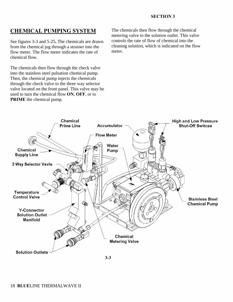
CHEMICAL PUMPING SYSTEM See figures 3-3 and 5-25. The chemicals are drawn from the chemical jug through a strainer into the flow meter. The flow meter indicates the rate of chemical flow. The chemicals then flow through the check valve into the stainless steel pulsation chemical pump. Then, the chemical pump injects the chemicals through the check valve to the three way selector valve located on the front panel. This valve may be used to turn the chemical flow ON, OFF, or to PRIME the chemical pump.
The chemicals then flow through the chemical metering valve to the solution outlet. This valve controls the rate of flow of chemical into the cleaning solution, which is indicated on the flow meter.
3-3
SECTION 3
BLUELINE THERMALWAVE II 19
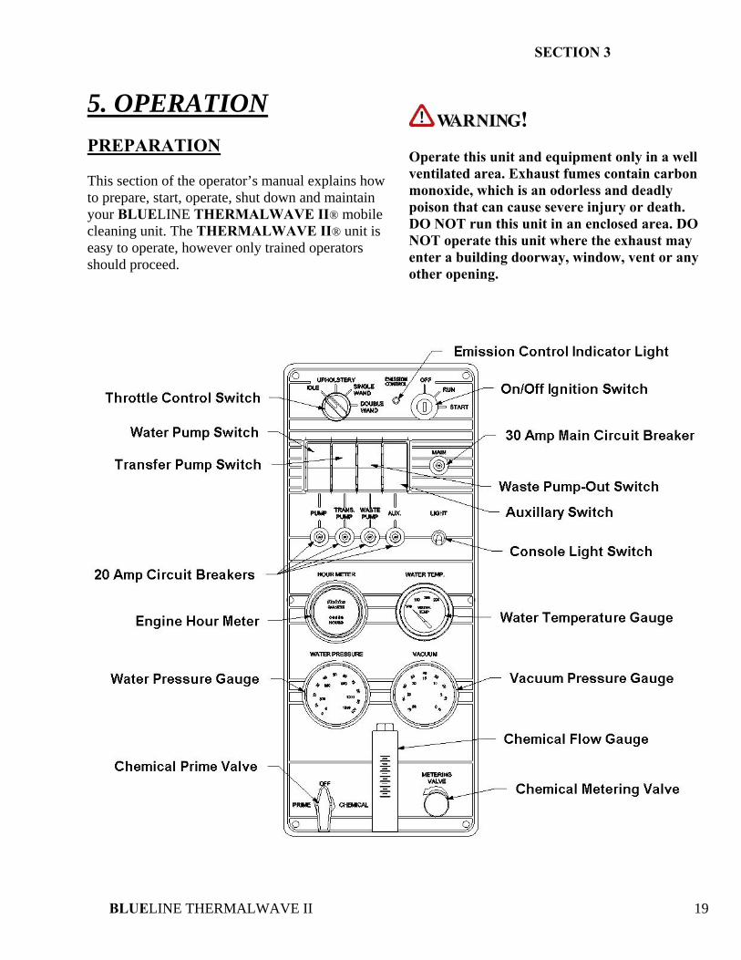
5. OPERATION PREPARATION This section of the operator’s manual explains how to prepare, start, operate, shut down and maintain your BLUELINE THERMALWAVE II® mobile cleaning unit. The THERMALWAVE II® unit is easy to operate, however only trained operators should proceed.
! Operate this unit and equipment only in a well ventilated area. Exhaust fumes contain carbon monoxide, which is an odorless and deadly poison that can cause severe injury or death. DO NOT run this unit in an enclosed area. DO NOT operate this unit where the exhaust may enter a building doorway, window, vent or any other opening.
SECTION 3
BLUELINE THERMALWAVE II 20
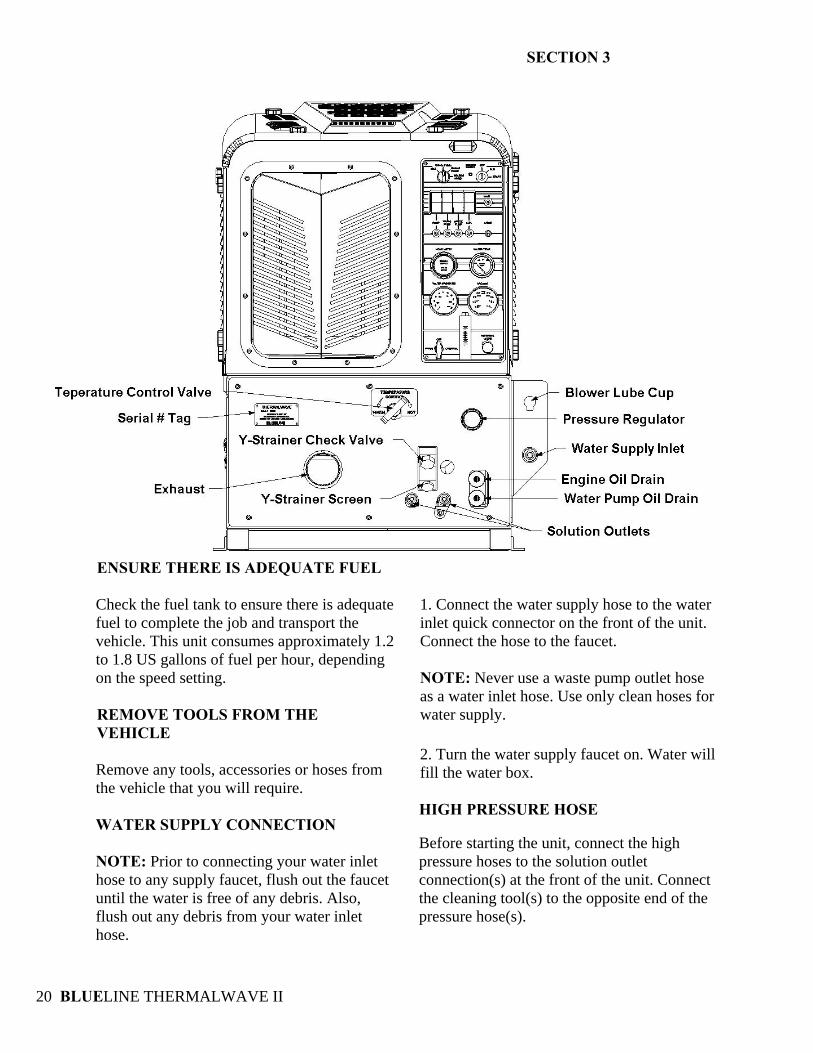
ENSURE THERE IS ADEQUATE FUEL Check the fuel tank to ensure there is adequate fuel to complete the job and transport the vehicle. This unit consumes approximately 1.2 to 1.8 US gallons of fuel per hour, depending on the speed setting. REMOVE TOOLS FROM THE VEHICLE Remove any tools, accessories or hoses from the vehicle that you will require. WATER SUPPLY CONNECTION NOTE: Prior to connecting your water inlet hose to any supply faucet, flush out the faucet until the water is free of any debris. Also, flush out any debris from your water inlet hose.
1. Connect the water supply hose to the water inlet quick connector on the front of the unit. Connect the hose to the faucet.
NOTE: Never use a waste pump outlet hose as a water inlet hose. Use only clean hoses for water supply.
2. Turn the water supply faucet on. Water will fill the water box. HIGH PRESSURE HOSE
Before starting the unit, connect the high pressure hoses to the solution outlet connection(s) at the front of the unit. Connect the cleaning tool(s) to the opposite end of the pressure hose(s).
SECTION 3
BLUELINE THERMALWAVE II 21
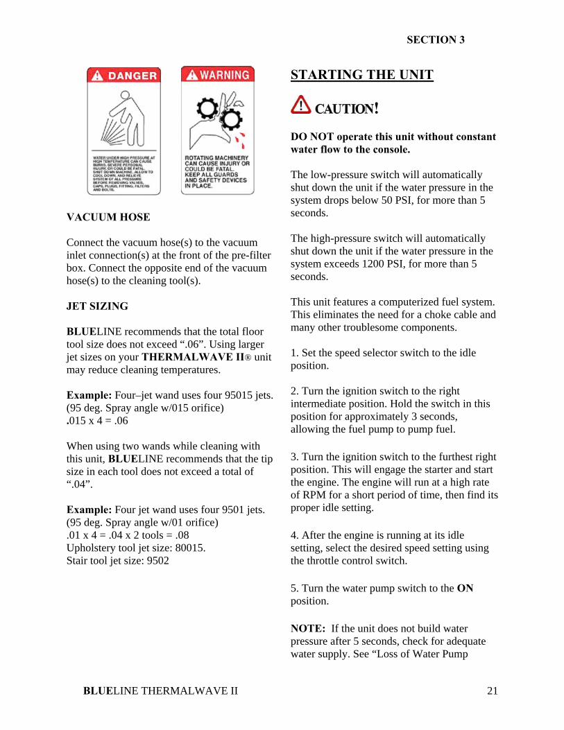
VACUUM HOSE Connect the vacuum hose(s) to the vacuum inlet connection(s) at the front of the pre-filter box. Connect the opposite end of the vacuum hose(s) to the cleaning tool(s). JET SIZING BLUELINE recommends that the total floor tool size does not exceed “.06”. Using larger jet sizes on your THERMALWAVE II® unit may reduce cleaning temperatures. Example: Four–jet wand uses four 95015 jets. (95 deg. Spray angle w/015 orifice) .015 x 4 = .06 When using two wands while cleaning with this unit, BLUELINE recommends that the tip size in each tool does not exceed a total of “.04”. Example: Four jet wand uses four 9501 jets. (95 deg. Spray angle w/01 orifice) .01 x 4 = .04 x 2 tools = .08 Upholstery tool jet size: 80015. Stair tool jet size: 9502
STARTING THE UNIT
! DO NOT operate this unit without constant water flow to the console. The low-pressure switch will automatically shut down the unit if the water pressure in the system drops below 50 PSI, for more than 5 seconds. The high-pressure switch will automatically shut down the unit if the water pressure in the system exceeds 1200 PSI, for more than 5 seconds. This unit features a computerized fuel system. This eliminates the need for a choke cable and many other troublesome components. 1. Set the speed selector switch to the idle position. 2. Turn the ignition switch to the right intermediate position. Hold the switch in this position for approximately 3 seconds, allowing the fuel pump to pump fuel. 3. Turn the ignition switch to the furthest right position. This will engage the starter and start the engine. The engine will run at a high rate of RPM for a short period of time, then find its proper idle setting. 4. After the engine is running at its idle setting, select the desired speed setting using the throttle control switch. 5. Turn the water pump switch to the ON position. NOTE: If the unit does not build water pressure after 5 seconds, check for adequate water supply. See “Loss of Water Pump
SECTION 3
BLUELINE THERMALWAVE II 22
Pressure in the “Troubleshooting section of this manual. Allow adequate time for the water temperature to warm up before cleaning, approximately 10-15 minutes. PRIMING THE CHEMICAL PUMP NOTE: BLUELINE recommends that the chemical pump be primed whenever the water pump is on. This eliminates possible pressure fluctuations and water pump pulsations related with running the chemical pump dry. 1. Insert the chemical prime tube and the chemical inlet tube into the chemical jug. NOTE: When inserting the chemical tube into the chemical jug, ensure that it stays fully submerged, as the chemical pump will not function if air is allowed to enter the inlet line. DO NOT operate the chemical pump without the inlet strainer properly installed. 2. Turn the 3-way chemical selector valve located on the control panel to the PRIME position. The chemical will then flow from the chemical jug through the chemical prime tube. If the pump does not prime, then:
A. Place the chemical prime tube into the vacuum hose and seal off the vacuum hose. The vacuum will quickly draw chemical from the chemical jug. After the flow begins, turn the chemical selector valve to OFF position, insert the chemical prime tube back into the jug, and turn the chemical selector valve back to the PRIME position and continue the procedure.
B. Once chemical flow with no air bubbles has been achieved, turn the chemical
selector valve from PRIME to METER. With the cleaning tool open, check the flow meter and adjust the chemical metering valve until the desired rate of chemical flow is achieved.
AUTOMATIC WASTE PUMP 1. If your unit is equipped with an optional automatic waste pump, connect one end of the 5/8 inch or larger garden hose to the pump-out connection and the other end to an acceptable waste disposal. 2. Turn the pump-out switch located on the front console control panel to the ON position. The waste pump will now operate automatically throughout the cleaning period. DO NOT use an outlet hose that is smaller than 5/8 in. I.D. NEVER use a waste pump hose as a water inlet hose.
! NEVER dispose of waste water in a storm drain, water way or on ground areas. Always dispose of waste in accordance with Local, State and Federal laws. OPERATION After you have completed the previous steps, proceed with the cleaning operation. Place the throttle control switch to the desired cleaning mode for carpet, or upholstery cleaning. A float shut-off switch is located inside of the waste tank. It will automatically shut down the unit if the tank reaches its full capacity. If this occurs, empty the waste tank before continuing.
SECTION 3
BLUELINE THERMALWAVE II 23
CLEANING While cleaning, observe the following guidelines: 1. Before cleaning, ensure that the wand nozzles are functioning properly.
A. Hold the wand approximately one foot above the surface to be cleaned and open the wand valve. A full even spray should emit from the cleaning nozzles.
B. If the nozzles are not showing a full
even spray pattern, adjust, clean, or replace the nozzles, if required.
2. Usually, chemical solution is applied during the push stroke of the wand during cleaning, and extraction is done on the pull stroke. For heavily soiled carpets, the wand may be used in a scrubbing action, with chemical solution applied in both push and pull strokes, provided that the final stroke is a pull stroke with no chemical injection. UPHOLSTERY CLEANING 1. Upholstery tools have a lower flow rate and smaller orifices. To accommodate the desired cleaning temperature, operate the unit in the upholstery mode, by setting the throttle control switch on the front control panel to upholstery. Adjust the temperature control valve to the desired temperature. To maintain proper cleaning temperatures, make certain that the unit has been fully heated up prior to cleaning. 2. Always clean upholstery with a pressure setting below 300 PSI, by using the pressure regulator on the unit.
STAIR TOOL CLEANING 1. Set the throttle control switch on the front control panel to the CARPET setting. Adjust the temperature control valve to the desired temperature. To maintain proper cleaning temperatures, make certain that the unit has been fully heated up prior to cleaning. FLOOD RESTORATION/EXTRACTION
! 1. Set the throttle control switch on the front control panel to the desired setting. Make certain that the water pump switch is in the OFF position. Proceed into the extraction process. NOTE: It may be necessary to activate water pump during prolonged operation in flood restoration/extraction to ensure adequate engine cooling. SHUT DOWN AND DAILY MAINTENANCE 1. Flush out the chemical system with fresh water to remove any chemical residue. 2. Remove as much moisture from the vacuum hoses as possible. This will prevent spillage of wastewater in your vehicle when returning hoses. 3. Disconnect the vacuum hoses from the front of the pre-filter box. 4. Turn the throttle control switch to the IDLE position. 5. Adjust the temperature control valve to the cold water position.
SECTION 3
BLUELINE THERMALWAVE II 24
6. Allow the unit to run for at least 2 minutes or until the water temperature is at or below 180 deg. F. This will also remove any moisture from the vacuum pump. NOTE: If shutting down for the day: Plug the vacuum inlets on the front of the unit and set the throttle switch to carpet. Spray WD-40 (or equivalent) into the blower lubrication cup, located above the vacuum inlets for 5 seconds. This will lubricate the vacuum pump. Next, return the throttle control switch to IDLE position, and continue step 4. 7. Turn the ignition switch to the OFF position. 8. Turn the water supply faucet off. Loosen the water supply hose at the water supply to bleed off the pressure. Unhook the water supply hose and return it to the vehicle. 9. Activate the valves on all cleaning tools. This will relieve any remaining pressure. Disconnect the cleaning tools and solution hoses and return them to the vehicle. 10. Drain the waste tank, disposing of wastewater in a suitable and proper location.
! NEVER dispose of wastewater in a storm drain, water way or on ground areas. Always dispose of waste in accordance with Local, State, and Federal laws. 11. Remove the strainer basket from the pre-filter box. Clean out any debris and re-install. NOTE: Damage may occur to the vacuum pump. Replacement and maintenance of the filter will prevent rust and corrosion from entering the vacuum pump.
12. Inspect the vacuum inlet filters inside the waste tank weekly. Remove and clean the filters if there is any lint or debris present. NOTE: To remove the vacuum inlet filter, grip the plastic hexagon section of the filter. Gripping the filter by the screen will collapse or destroy the filter. Replace the filter after cleaning until hand tight. NEVER operate this unit with the filter removed, damaged or improperly installed. 13. At the end of the work day, rinse out the waste tank with fresh water. A deodorizer may be added to prevent bacterial growth. 14. Clean the vehicle interior, unit, tools, hoses etc., as needed. Inspect ALL equipment and accessories for any damage, leaks, wear, etc. FREEZE PROTECTION
! If the unit is exposed to freezing weather conditions, the water inside of the unit may freeze, resulting in SERIOUS DAMAGE to the unit. The following is recommended to prevent this from occurring during the cold weather season: 1. Always park the unit in a heated building when not in use. 2. While out in operation, avoid long periods of shut down as the unit generates heat while running. Keep the unit running just prior to leaving for the next job. 3. If a heated building is not available, winterize the unit with anti-freeze. It is not possible to winterize units that have auxiliary water tanks. If the unit has
SECTION 3
BLUELINE THERMALWAVE II 25
an auxiliary water tank(s), it must be stored in a heated building. WINTERIZING YOUR UNIT WITH ANTI-FREEZE: 1. Shut off the water supply to the unit and disconnect the water inlet hose from the console. 2. Connect all solution hoses and tools that may have water in them, to the console. 3. Start the unit with the water pump in the ON position. Open a tool valve. This will result in the low-pressure switch shutting down the unit when the water box is emptied. 4. Fill the water box with two gallons of 100% glycol based anti-freeze. 5. Start the unit and set the throttle control to the IDLE position. Turn the water pump switch to the ON position. Open a tool valve until anti-freeze comes out of the tool. Repeat this procedure with ALL remaining tools and hoses. 6. After the tools and solution hoses have been filled with anti-freeze, disconnect and store them. Recover all anti-freeze that comes out of the tools and hoses and store in an approved container. ALWAYS re-use and re-cycle anti-freeze. 7. Prime the chemical injection system with a 100% glycol based antifreeze. Insert the chemical inlet and prime tube into the anti-freeze container. Turn the chemical valve to PRIME until anti-freeze comes out of the prime hose. Turn the chemical valve to the ON (chemical) position. Ensure that the flow meter indicates flow. Ensure that all anti-
freeze that comes out of the chemical hose goes into an approved container. After 25 seconds, turn the chemical valve to the OFF position. 8. Adjust the temperature control valve to the cold water position. Allow the unit to run for at least 3 minutes. The unit is now winterized. REMOVING ANTI-FREEZE FROM THE UNIT: 1. Connect the solution hoses to the unit, with a tool attached to the opposite end. Start the unit. Turn the water pump on. Open the tool valve and ensure that the anti-freeze goes into an approved container. Allow the anti-freeze to flow into the container until the low- pressure switch shuts the unit down. 2. Fill the water box with fresh water and repeat step 1. 3. Connect the water inlet hose to the unit and turn the water supply on. Connect all tools and solution hoses that were winterized to the solution outlet connections. Open all tool valves and drain the anti-freeze into an approved container until the water runs clear and all of the anti-freeze is purged from the hoses and tools. 4. Insert the chemical prime hose into the approved container. Submerge the chemical hose into fresh water. Turn the chemical valve to the PRIME position until the water runs clear through the prime hose. Remove the prime hose from the container. 5. Turn the chemical valve to the ON (chemical) position. This will allow water to flow to the other side of the system.
SECTION 3
BLUELINE THERMALWAVE II 26
After all of the anti-freeze has been removed, the unit is ready to operate. The anti-freeze in your approved storage container will eventually become diluted with water. When the anti-freeze level drops below 70% of the total mixture, properly dispose of it and start over with fresh 100% anti-freeze.
! DO NOT drain used anti-freeze on the ground or into storm drains. Dispose of anti-freeze only in an approved location. Observe Local, State and Federal laws when disposing of anti-freeze.
BLUELINE THERMALWAVE II 27
SECTION 4: SERVICE & MAINTENANCE
6. MAINTENANCE Maintenance Chart 29 Engine 30 Vacuum Pump 31 Water Pump 31 Vacuum Inlet Filter 32 Drive Belts, Pulleys and Hubs 32 Water Box / Water Pump Inlet Filter 32 Strainer Basket 32 Y-Strainer (Outlet) 33 Check Valve (Outlet) 33 Chemical Pump, Chemical Metering System 33 Stainless Steel Accumulator 33 Pressure Regulator 33 Vacuum Hoses 33 Battery 33 High Pressure Solution Hoses 34 7. GENERAL SERVICE ADJUSTMENTS
Engine 34 Vacuum Relief Valve 34 Vacuum Pump Drive Belts 34 Water Pump Drive Belt 34 Float Valve 35 Solution Outlet Check Valve 35 Chemical Pump 35 Packing Nut Adjustment, Chemical Metering & Selector Valves 36 Pressure Regulator 36 Adding/Draining Engine Coolant 37
BLUELINE THERMALWAVE II 28
8. TROUBLESHOOTING Water Pump 38 Chemical System 39 Blower / Vacuum Pump 40 Engine Will Not Start 41 Engine Does Not Crank 42 System Safety Shut Down 43 Z.E.E.M.S. 44 Z.E.E.M.S. Trouble Codes 45 Heating System 46
BLUELINE THERMALWAVE II 29
MAINTENANCE CHART Engine Daily Check engine oil level.** Fill to proper level.
Engine Coolant Daily Check coolant level in overflow bottle. Fill to proper level. Vacuum Pump Daily Spray WD-40 (or Equivalent) into the lubrication cup for 5 seconds. Water Pump Daily Check water pump oil level.*** Fill to proper level.
Vacuum Inlet Filter Daily* Inspect filter, clean and or replace if required. Waste Tank Strainer Basket Daily Empty and clean stainless steel basket.
Vacuum Hoses Daily Rinse with fresh water. Waste Pump-Out (Optional) Daily* Inspect and remove any debris or sediment.
Engine Weekly Check air cleaner for damaged, dirty, or loose parts. Engine Weekly Inspect air intake and cooling areas. Clean if required.
Vacuum Pump Weekly* Check vacuum pump oil level. Fill to proper level. Do not overfill. Vacuum Inlet Filter Weekly Remove filter and clean.
Water Box Weekly* Inspect and clean filter. Replace if damaged. Battery Weekly* Check fluid level. Fill with distilled water only. Do not overfill. Engine Monthly Inspect drive belts for wear. Replace as needed.
Water Box Monthly Check float valve for proper operation. Y-Strainer Monthly* Clean and remove any debris.****
High Pressure Solution Hoses 25 Hours Inspect for wear, damage, or impending rupture. Replace if damaged. Engine 100 Hours Change engine oil and filter.
Vacuum Pump 100 Hours Grease bearings with extreme pressure bearing grease. Pressure Regulator 100 Hours Lubricate o-rings. Use only o-ring lubricant part # 13-003.
Battery 100 Hours Clean battery terminals. Engine 200 Hours Check spark plugs and clean if necessary. Engine 200 Hours Clean engine air filter.
Chemical Metering System 200 Hours Inspect packing nut on selector and metering valve. Adjust as needed. Engine 500 Hours Change engine coolant. Engine 500 Hours Replace in-line fuel filter.******
Water Pump 500 Hours Change crankcase oil.*** Pulleys and Hubs 500 Hours Check pulley and hub set screws for proper torque.*****
Stainless Steel Accumulator 500 Hours Check pressure. Recharge and change bladder if needed.****** Engine 1000 Hours Replace spark plugs.
Vacuum Pump 1000 Hours Drain, flush, and replace oil.******* Chemical Pump 1000 Hours Change diaphragm and check valves. Inspect disk.
Check Valve 1000 Hours Check Teflon seat for abnormal wear or debris. Replace as needed. Engine 2000 Hours Replace air filter element.
To maximize the operating life and performance, use only recommended oils, filters and greases.
*Or as often as required. **Change engine oil and oil filter after first 50 hours of operation. ***Change water pump crankcase oil after first 50 hours of operation ****Inspect after first week of operation, and remove any debris present. Inspect again after 2 to 4 weeks. *****Check pulley and hub set screws after first 50 hours of operation, and again at 100 hours of operation. ******Or every 6 Months. Whichever comes first. *******Or Yearly. Whichever comes first.
SECTION 4
BLUELINE THERMALWAVE II 30
6. MAINTENANCE This section of the operator’s manual contains the service and maintenance information for the THERMALWAVE II® unit. A planned preventative maintenance program will ensure that your BLUELINE THERMALWAVE II® has optimum performance, long operating life, and a minimum amount of down time.
! DO NOT attempt to service this unit while it is running. High speed parts as well as high temperature components may result in severe injury, severed limbs, or fatality. NOTE: Refer to the hour meter as a guide for coordinating a maintenance schedule.
ENGINE The BLUELINE THERMALWAVE II® unit features a computerized electronic fuel system. DO NOT attempt to service or repair this system without authorization from the factory. 1. Check the engine oil level daily. Ensure that the proper oil level is maintained. NEVER overfill. 2. Change the oil after the first 50 hours of operation, after the “break-in” period. Thereafter, change oil every 100 hours of operation. USE ONLY NISSAN BRAND OIL FILTERS. USE OF ANY OTHER TYPE OF OIL FILTER WILL VOID ENGINE WARRANTY. Oil Recommendation. Use only high quality detergent oil of at least API (American Petroleum Institute) service class SH. Determine the viscosity based on the air temperature at the time of operation as outlined in the following table.
NOTE: The use of less than service class SH oil or extending the oil change intervals longer than recommended can result in engine damage. 3. Check the spark plugs every 200 hours and clean if necessary. Replace spark plugs every 1000 hours. NEVER sandblast spark plugs. Spark plugs should be cleaned only by scraping or wire brushing.
SECTION 4
BLUELINE THERMALWAVE II 31
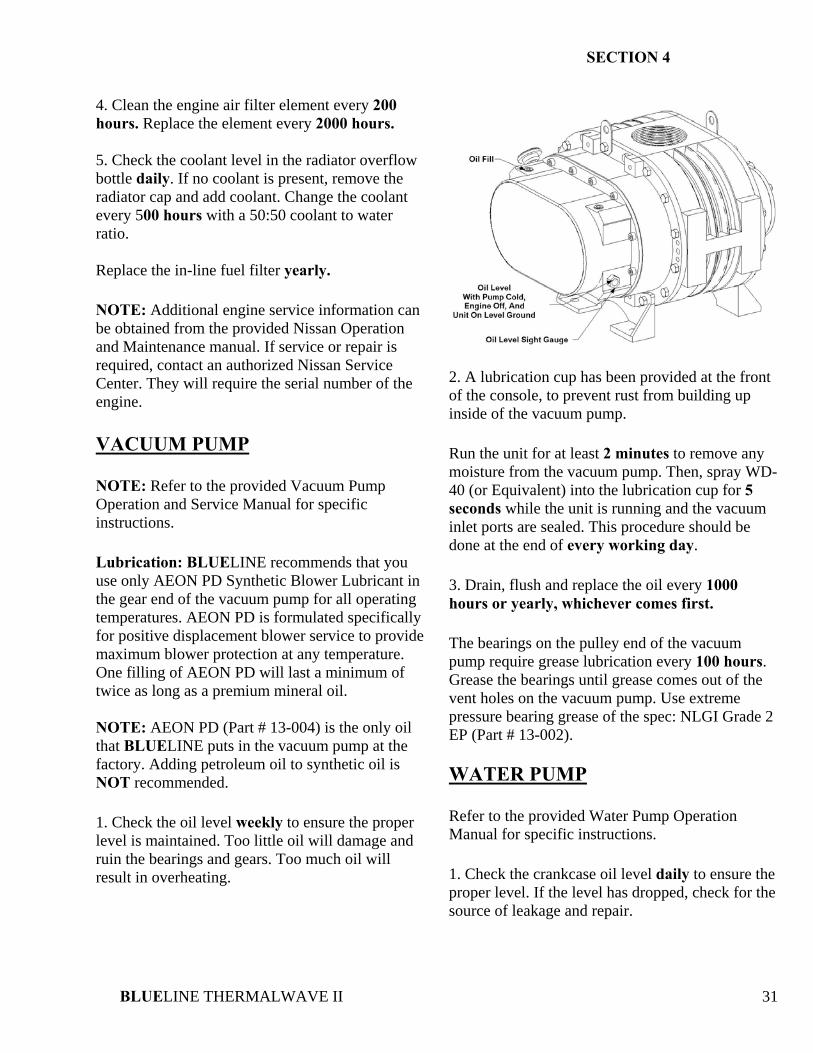
4. Clean the engine air filter element every 200 hours. Replace the element every 2000 hours. 5. Check the coolant level in the radiator overflow bottle daily. If no coolant is present, remove the radiator cap and add coolant. Change the coolant every 500 hours with a 50:50 coolant to water ratio. Replace the in-line fuel filter yearly. NOTE: Additional engine service information can be obtained from the provided Nissan Operation and Maintenance manual. If service or repair is required, contact an authorized Nissan Service Center. They will require the serial number of the engine. VACUUM PUMP NOTE: Refer to the provided Vacuum Pump Operation and Service Manual for specific instructions. Lubrication: BLUELINE recommends that you use only AEON PD Synthetic Blower Lubricant in the gear end of the vacuum pump for all operating temperatures. AEON PD is formulated specifically for positive displacement blower service to provide maximum blower protection at any temperature. One filling of AEON PD will last a minimum of twice as long as a premium mineral oil. NOTE: AEON PD (Part # 13-004) is the only oil that BLUELINE puts in the vacuum pump at the factory. Adding petroleum oil to synthetic oil is NOT recommended. 1. Check the oil level weekly to ensure the proper level is maintained. Too little oil will damage and ruin the bearings and gears. Too much oil will result in overheating.
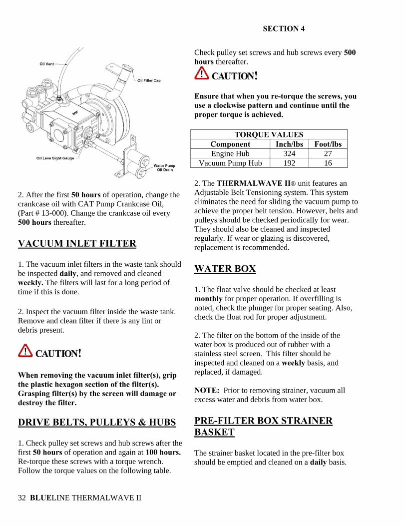
2. A lubrication cup has been provided at the front of the console, to prevent rust from building up inside of the vacuum pump. Run the unit for at least 2 minutes to remove any moisture from the vacuum pump. Then, spray WD-40 (or Equivalent) into the lubrication cup for 5 seconds while the unit is running and the vacuum inlet ports are sealed. This procedure should be done at the end of every working day. 3. Drain, flush and replace the oil every 1000 hours or yearly, whichever comes first. The bearings on the pulley end of the vacuum pump require grease lubrication every 100 hours. Grease the bearings until grease comes out of the vent holes on the vacuum pump. Use extreme pressure bearing grease of the spec: NLGI Grade 2 EP (Part # 13-002). WATER PUMP Refer to the provided Water Pump Operation Manual for specific instructions. 1. Check the crankcase oil level daily to ensure the proper level. If the level has dropped, check for the source of leakage and repair.
SECTION 4
BLUELINE THERMALWAVE II 32
2. After the first 50 hours of operation, change the crankcase oil with CAT Pump Crankcase Oil, (Part # 13-000). Change the crankcase oil every 500 hours thereafter. VACUUM INLET FILTER 1. The vacuum inlet filters in the waste tank should be inspected daily, and removed and cleaned weekly. The filters will last for a long period of time if this is done. 2. Inspect the vacuum filter inside the waste tank. Remove and clean filter if there is any lint or debris present.
! When removing the vacuum inlet filter(s), grip the plastic hexagon section of the filter(s). Grasping filter(s) by the screen will damage or destroy the filter. DRIVE BELTS, PULLEYS & HUBS 1. Check pulley set screws and hub screws after the first 50 hours of operation and again at 100 hours. Re-torque these screws with a torque wrench. Follow the torque values on the following table.
Check pulley set screws and hub screws every 500 hours thereafter.
! Ensure that when you re-torque the screws, you use a clockwise pattern and continue until the proper torque is achieved.
TORQUE VALUES Component Inch/lbs Foot/lbs Engine Hub 324 27
Vacuum Pump Hub 192 16 2. The THERMALWAVE II® unit features an Adjustable Belt Tensioning system. This system eliminates the need for sliding the vacuum pump to achieve the proper belt tension. However, belts and pulleys should be checked periodically for wear. They should also be cleaned and inspected regularly. If wear or glazing is discovered, replacement is recommended. WATER BOX 1. The float valve should be checked at least monthly for proper operation. If overfilling is noted, check the plunger for proper seating. Also, check the float rod for proper adjustment. 2. The filter on the bottom of the inside of the water box is produced out of rubber with a stainless steel screen. This filter should be inspected and cleaned on a weekly basis, and replaced, if damaged. NOTE: Prior to removing strainer, vacuum all excess water and debris from water box. PRE-FILTER BOX STRAINER BASKET The strainer basket located in the pre-filter box should be emptied and cleaned on a daily basis.
SECTION 4
BLUELINE THERMALWAVE II 33
Y-STRAINER (OUTLET) Unscrew the screen and inspect the Y-strainer after the first week of operation. Remove any debris present. Inspect again after 2 and 4 weeks. Thereafter, inspect the Y-strainer and screen at least monthly. If a frequent build-up of debris is noticed, inspect and clean more frequently. CHECK VALVE (OUTLET) Inspect the check valve when servicing the chemical pump or as needed. Remove the check valve from the Y-strainer assembly and disassemble. Check the Teflon seat for abnormal wear or debris. Replace the Teflon seat if necessary. Improper seating of the check valve poppet, damaged spring, or o-rings will result in poor operation of the chemical system. CHEMICAL PUMP The chemical pump should be rebuilt every 1000 hours. This involves changing the diaphragm, check valves, and inspecting the disk. CHEMICAL METERING SYSTEM Check and inspect the packing nut on the chemical selector and metering valves every 200 hours. Keeping the valve packings properly adjusted will prevent leaks and add to the overall life of the valves. STAINLESS STEEL ACCUMULATOR Sealed 250 pound nitrogen accumulator. Change every 2000 hours or as needed.
PRESSURE REGULATOR Lubricate the o-rings in the pressure regulator every 100 hours. Use only o-ring lubricant (Part # 13-003). VACUUM HOSES To ensure maximum hose life, BLUELINE recommends that you wash out the hoses with fresh water daily. BATTERY
! Explosive gases, Dangerous acid! Batteries contain sulfuric acid. To prevent acid burns, avoid contact with skin, eyes and clothing. Batteries also produce explosive hydrogen gases while charging. To prevent fire or explosion, charge batteries only in a well ventilated area. Keep sparks, open flames, as well as any other sources of ignition away from batteries at all times. Remove all jewelry prior to servicing batteries. Keep batteries out of the reach of children. Before disconnecting the negative (-) ground cable, ensure that all switches are in the OFF position. If ON, a spark could occur at the ground connection terminal, which could cause an explosion if hydrogen gas or gasoline vapors are present. ALWAYS disconnect the negative (-) terminal first. 1. Check the fluid level in the battery at least once a week. If low, fill to the recommended level ONLY with distilled water. DO NOT overfill the battery. Early failure or poor performance will result due to loss of electrolyte. 2. Keep cables, terminals and external surfaces of the battery clean and dry. A buildup of corrosive
SECTION 4
BLUELINE THERMALWAVE II 34
acid or grime on the external surfaces could cause the battery to self-discharge. 3. Battery terminals should be cleaned every 100 hours to prevent corrosion buildup. Wash the cables, terminals and external surfaces with a mild baking soda and water solution. Rinse thoroughly with fresh water. DO NOT allow baking soda to enter the battery cells, as this will destroy the electrolyte, resulting in battery failure. HIGH PRESSURE SOLUTION HOSES Inspect your high-pressure solution hoses for wear after the first 100 hours. Thereafter, inspect every 25 hours. If the hoses show any signs of damage or impending rupture, replace the hoses.
! NEVER attempt to repair high-pressure solution hoses. Repairing high-pressure solution hoses may result in severe burns and serious injury. All high-pressure solution hoses must be rated for 3000 PSI at 250 deg. F. Thermoplastic hoses do not meet this requirement and should not be used. Severe burns and injury may result if the hoses do not meet these requirements.
7. GENERAL SERVICE ADJUSTMENTS
! DO NOT attempt to service this unit while it is running. High speed parts as well as high temperature components may result in severe injury, severed limbs, or fatality. ENGINE The BLUELINE THERMALWAVE II® unit features a computerized fuel system. DO NOT attempt to service or repair this system without authorization from the factory. VACUUM RELIEF VALVE With the unit running at full RPM, block off the airflow at the vacuum inlet ports and read the vacuum gauge. If adjustment is required, shut the unit down and adjust the locking nut tension on the vacuum relief valve. Re-start the unit and read the vacuum gauge. Repeat this process until the vacuum relief valve opens at 13” Hg. VACUUM PUMP DRIVE BELTS The THERMALWAVE II® unit is equipped with an Adjustable Belt Tensioning system. This eliminates the need for sliding the vacuum pump for belt adjustment. Periodic checking of the belts and pulley condition is all that is required. WATER PUMP DRIVE BELT To tighten the water pump belt: 1. Loosen the four nuts, which hold the water pump base to the frame.
SECTION 4
BLUELINE THERMALWAVE II 35
2. Adjust the position of the belt tensioning adjusting bolt until the proper belt tension is achieved. (3/4” deflection in the center of the belts, half way between the pulleys). 3. While checking the alignment, tighten the nuts that hold the water pump to the base. FLOAT VALVE (WATER BOX) The float valve should only be adjusted if the water box is overflowing or the water level in the water box is low. 1. If the water box is overflowing, remove and check the float valve for damage, or debris. If the float ball has any water inside of it, it must be replaced.
! IF replacing the float ball, DO NOT over-tighten the float rod, as it can puncture the ball. Ensure that the nuts are tightened on the rod. SOLUTION OUTLET CHECK VALVE Inspect the check valve whenever performing service on the chemical pump or if flow problems are occurring in the chemical system. 1. Remove the check valve, ensuring that the small o-ring on the seat comes out with it 2. Next, remove the seat using a 5/16 in. Allen wrench 3. Check the Teflon seat for wear or debris. Clean and replace the seat if necessary. 4. Inspect the poppet and the spring for wear or damage. Clean and replace as necessary.
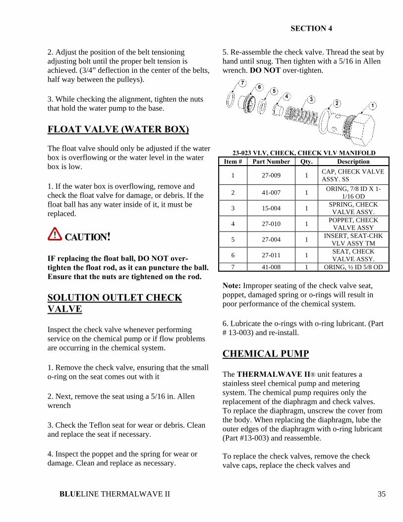
5. Re-assemble the check valve. Thread the seat by hand until snug. Then tighten with a 5/16 in Allen wrench. DO NOT over-tighten.
23-023 VLV, CHECK, CHECK VLV MANIFOLD
Item # Part Number Qty. Description
1 27-009 1 CAP, CHECK VALVE ASSY. SS
2 41-007 1 ORING, 7/8 ID X 1-1/16 OD
3 15-004 1 SPRING, CHECK VALVE ASSY.
4 27-010 1 POPPET, CHECK VALVE ASSY
5 27-004 1 INSERT, SEAT-CHK VLV ASSY TM
6 27-011 1 SEAT, CHECK VALVE ASSY.
7 41-008 1 ORING, ½ ID 5/8 OD Note: Improper seating of the check valve seat, poppet, damaged spring or o-rings will result in poor performance of the chemical system. 6. Lubricate the o-rings with o-ring lubricant. (Part # 13-003) and re-install. CHEMICAL PUMP The THERMALWAVE II® unit features a stainless steel chemical pump and metering system. The chemical pump requires only the replacement of the diaphragm and check valves. To replace the diaphragm, unscrew the cover from the body. When replacing the diaphragm, lube the outer edges of the diaphragm with o-ring lubricant (Part #13-003) and reassemble. To replace the check valves, remove the check valve caps, replace the check valves and
SECTION 4
BLUELINE THERMALWAVE II 36
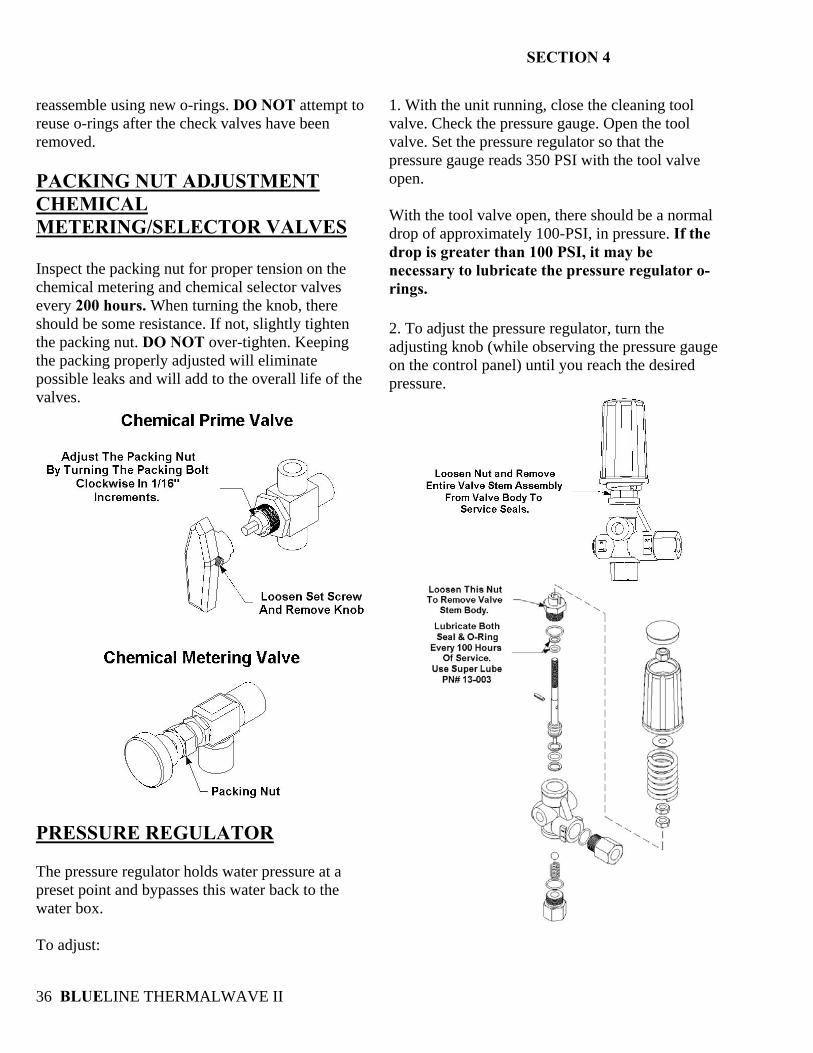
reassemble using new o-rings. DO NOT attempt to reuse o-rings after the check valves have been removed. PACKING NUT ADJUSTMENT CHEMICAL METERING/SELECTOR VALVES Inspect the packing nut for proper tension on the chemical metering and chemical selector valves every 200 hours. When turning the knob, there should be some resistance. If not, slightly tighten the packing nut. DO NOT over-tighten. Keeping the packing properly adjusted will eliminate possible leaks and will add to the overall life of the valves.
PRESSURE REGULATOR The pressure regulator holds water pressure at a preset point and bypasses this water back to the water box. To adjust:
1. With the unit running, close the cleaning tool valve. Check the pressure gauge. Open the tool valve. Set the pressure regulator so that the pressure gauge reads 350 PSI with the tool valve open. With the tool valve open, there should be a normal drop of approximately 100-PSI, in pressure. If the drop is greater than 100 PSI, it may be necessary to lubricate the pressure regulator o-rings. 2. To adjust the pressure regulator, turn the adjusting knob (while observing the pressure gauge on the control panel) until you reach the desired pressure.
SECTION 4
BLUELINE THERMALWAVE II 37
ADDING/DRAINING ENGINE COOLANT Use a 50:50 coolant to water ratio in this unit’s cooling system. 1. To drain the coolant, remove the upper radiator cap and turn the lower radiator draincock counter-clockwise. Open the draincock on the heli-coil assembly, until drained. Dispose of anti-freeze only in an approved location 2. To add coolant, fill the radiator, then bleed the air out of the system by turning the draincock on the heli-coil counter-clockwise. The heli-coil assembly is located on the right hand side of the console while facing the front of the unit. After bleeding the air out of the heli-coil draincock, close the draincock by turning it clockwise. Fill the engine radiator again. Next, fill the overflow container ONLY halfway between the “add” and “fill” marks. After running the unit, if necessary, add more coolant to the overflow container only.
8. TROUBLESHOOTING
! DO NOT attempt to service this unit while it is running. High-speed parts as well as high temperature components may result in severe injury, severed limbs or fatality. This section of the operator’s manual describes how to look for and repair malfunctions, which may occur. Accurate troubleshooting is based on a thorough and complete understanding of the WATER, CHEMICAL, VACCUM, HEAT TRANSFER, SAFETY and WIRING systems featured in this unit. If there are malfunctions occurring on this unit which you do not understand, refer back to the OPERATION section of this manual and review SYSTEMS.
SECTION 4
BLUELINE THERMALWAVE II 38
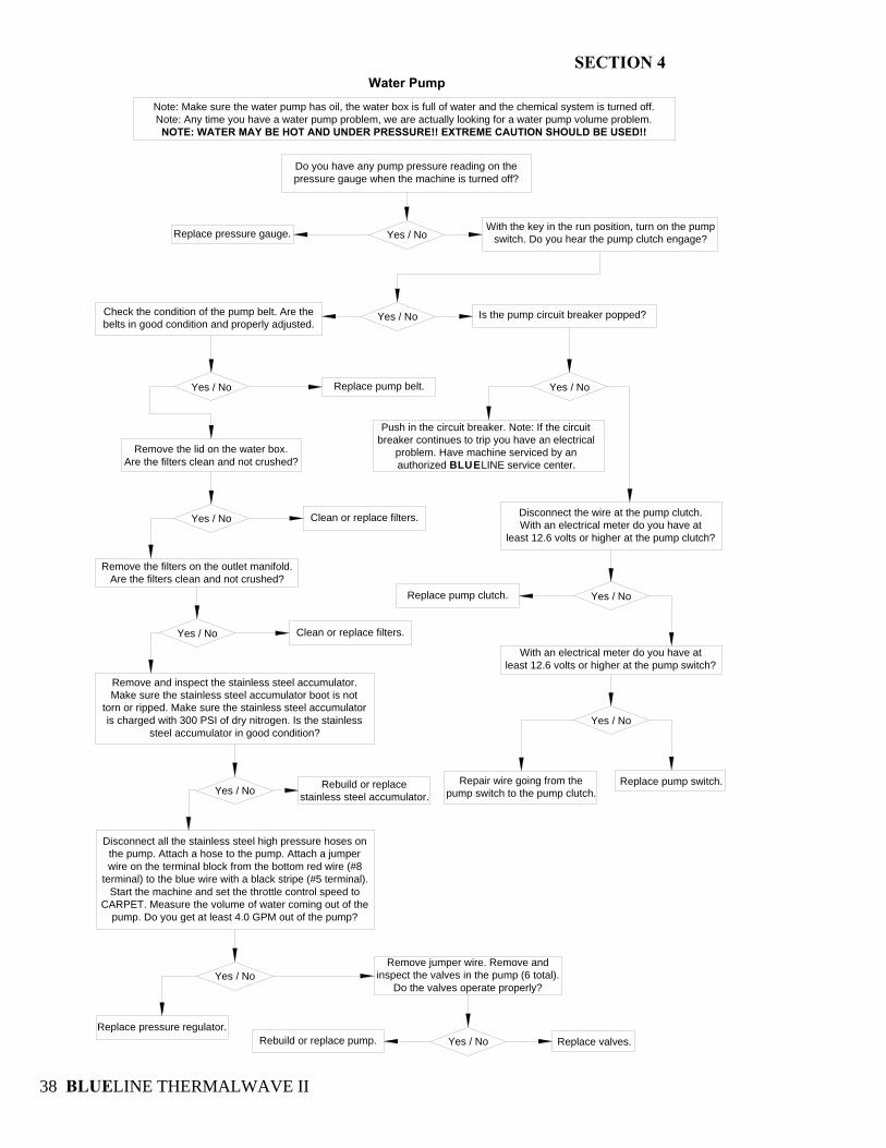
Water Pump
Note: Make sure the water pump has oil, the water box is full of water and the chemical system is turned off.Note: Any time you have a water pump problem, we are actually looking for a water pump volume problem.NOTE: WATER MAY BE HOT AND UNDER PRESSURE!! EXTREME CAUTION SHOULD BE USED!!
Yes / No
Yes / No
Yes / No
Do you have any pump pressure reading on the pressure gauge when the machine is turned off?
Replace pressure gauge.
Is the pump circuit breaker popped?
Replace pump belt. Yes / No
Yes / No
Yes / No
With the key in the run position, turn on the pump switch. Do you hear the pump clutch engage?
Push in the circuit breaker. Note: If the circuit breaker continues to trip you have an electrical
problem. Have machine serviced by an authorized BLUELINE service center.
Disconnect the wire at the pump clutch.With an electrical meter do you have at
least 12.6 volts or higher at the pump clutch?
Remove the lid on the water box.Are the filters clean and not crushed?
Clean or replace filters.
Replace pump clutch.
With an electrical meter do you have atleast 12.6 volts or higher at the pump switch?
Yes / No
Replace pump switch.Repair wire going from the pump switch to the pump clutch.
Yes / No
Remove the filters on the outlet manifold.Are the filters clean and not crushed?
Clean or replace filters.
Remove and inspect the stainless steel accumulator. Make sure the stainless steel accumulator boot is not
torn or ripped. Make sure the stainless steel accumulator is charged with 300 PSI of dry nitrogen. Is the stainless
steel accumulator in good condition?
Yes / No Rebuild or replacestainless steel accumulator.
Disconnect all the stainless steel high pressure hoses on the pump. Attach a hose to the pump. Attach a jumper wire on the terminal block from the bottom red wire (#8
terminal) to the blue wire with a black stripe (#5 terminal). Start the machine and set the throttle control speed to
CARPET. Measure the volume of water coming out of the pump. Do you get at least 4.0 GPM out of the pump?
Yes / No
Replace pressure regulator.
Remove jumper wire. Remove and inspect the valves in the pump (6 total).
Do the valves operate properly?
Rebuild or replace pump. Yes / No Replace valves.
Check the condition of the pump belt. Are thebelts in good condition and properly adjusted.
SECTION 4
BLUELINE THERMALWAVE II 39
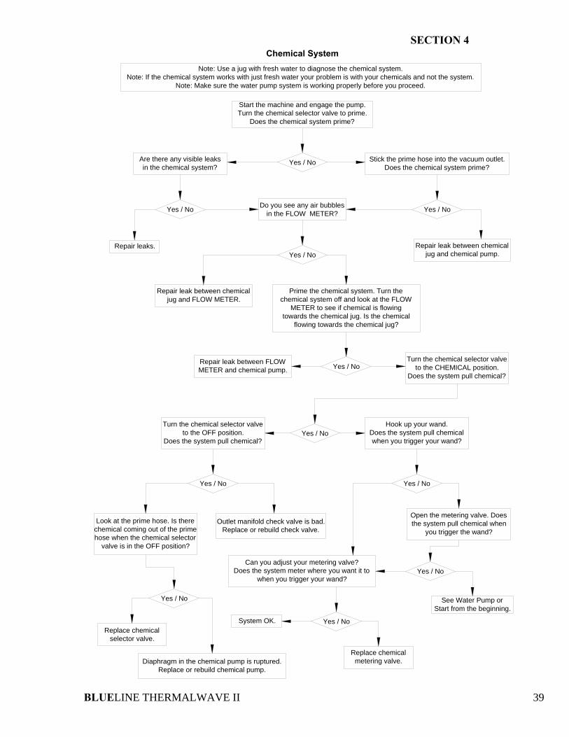
Chemical SystemNote: Use a jug with fresh water to diagnose the chemical system.
Note: If the chemical system works with just fresh water your problem is with your chemicals and not the system.Note: Make sure the water pump system is working properly before you proceed.
Yes / No
Yes / No
Yes / No
Start the machine and engage the pump. Turn the chemical selector valve to prime.
Does the chemical system prime?
Yes / No
Yes / No
Can you adjust your metering valve?Does the system meter where you want it to
when you trigger your wand?
Replace chemicalselector valve.
See Water Pump orStart from the beginning.
Are there any visible leaksin the chemical system?
Stick the prime hose into the vacuum outlet.Does the chemical system prime?
Yes / No Yes / No
Repair leaks. Repair leak between chemicaljug and chemical pump.
Do you see any air bubblesin the FLOW METER?
Yes / No
Repair leak between chemicaljug and FLOW METER.
Prime the chemical system. Turn the chemical system off and look at the FLOW
METER to see if chemical is flowing towards the chemical jug. Is the chemical
flowing towards the chemical jug?
Yes / NoRepair leak between FLOWMETER and chemical pump.
Turn the chemical selector valve to the CHEMICAL position.
Does the system pull chemical?
Turn the chemical selector valve to the OFF position.
Does the system pull chemical?
Hook up your wand.Does the system pull chemical when you trigger your wand?
Look at the prime hose. Is there chemical coming out of the prime hose when the chemical selector
valve is in the OFF position?
Open the metering valve. Does the system pull chemical when
you trigger the wand?Outlet manifold check valve is bad.
Replace or rebuild check valve.
Diaphragm in the chemical pump is ruptured.Replace or rebuild chemical pump.
Yes / No
Yes / NoSystem OK.
Replace chemicalmetering valve.
SECTION 4
BLUELINE THERMALWAVE II 40
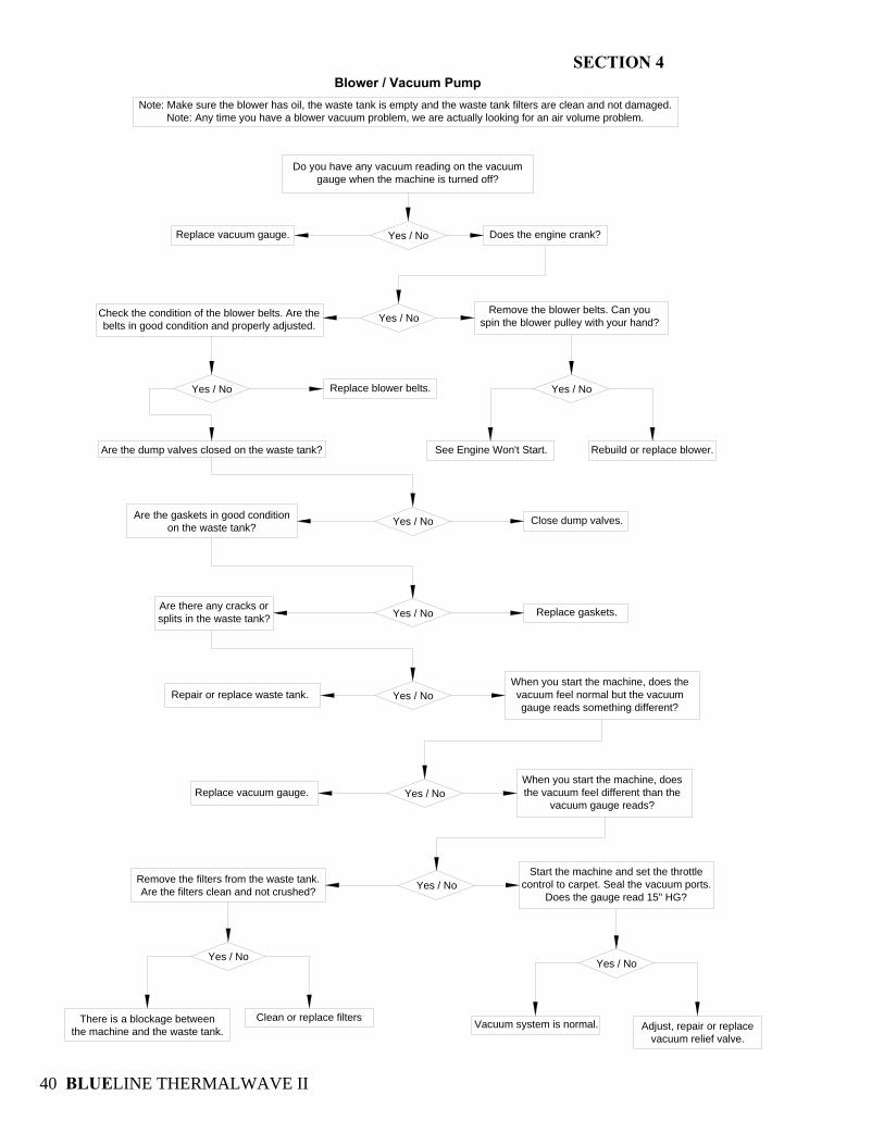
Blower / Vacuum PumpNote: Make sure the blower has oil, the waste tank is empty and the waste tank filters are clean and not damaged.
Note: Any time you have a blower vacuum problem, we are actually looking for an air volume problem.
Yes / No
Yes / No
Yes / No
Rebuild or replace blower.
Do you have any vacuum reading on the vacuum gauge when the machine is turned off?
Replace vacuum gauge.
Remove the blower belts. Can youspin the blower pulley with your hand?
Check the condition of the blower belts. Are the belts in good condition and properly adjusted.
Replace blower belts. Yes / No
Yes / NoWhen you start the machine, does thevacuum feel normal but the vacuumgauge reads something different?
Yes / No
Yes / NoRemove the filters from the waste tank.Are the filters clean and not crushed?
Yes / No
Are the dump valves closed on the waste tank?
Are the gaskets in good conditionon the waste tank?
Yes / No
Does the engine crank?
See Engine Won't Start.
Close dump valves.
Replace gaskets.Are there any cracks orsplits in the waste tank?
Replace vacuum gauge.When you start the machine, doesthe vacuum feel different than the
vacuum gauge reads?
Start the machine and set the throttlecontrol to carpet. Seal the vacuum ports.
Does the gauge read 15" HG?
Vacuum system is normal.
Yes / No
Clean or replace filtersThere is a blockage between the machine and the waste tank.
Yes / No
Adjust, repair or replacevacuum relief valve.
Repair or replace waste tank.
SECTION 4
BLUELINE THERMALWAVE II 41
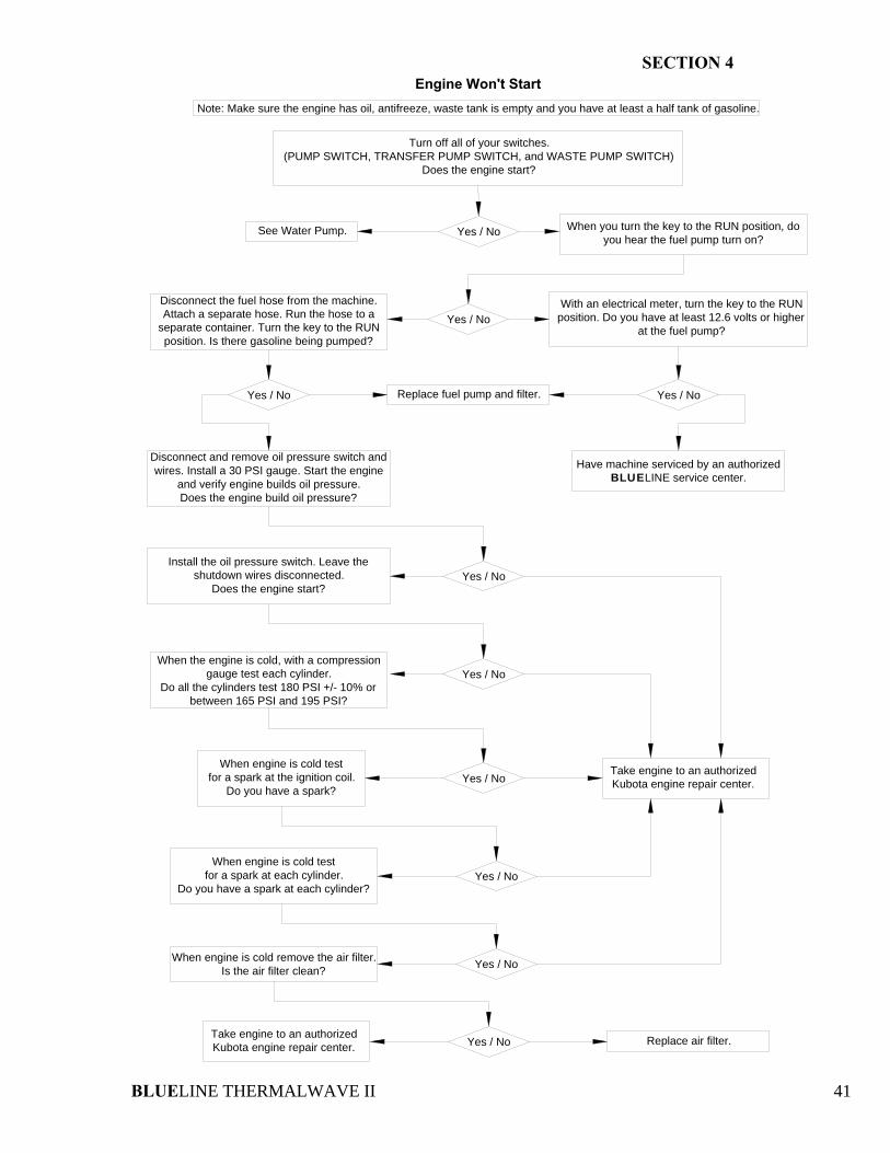
Engine Won't StartNote: Make sure the engine has oil, antifreeze, waste tank is empty and you have at least a half tank of gasoline.
Yes / No
Yes / No
Yes / No
When engine is cold testfor a spark at the ignition coil.
Do you have a spark?
Have machine serviced by an authorizedBLUELINE service center.
Turn off all of your switches.(PUMP SWITCH, TRANSFER PUMP SWITCH, and WASTE PUMP SWITCH)
Does the engine start?
When you turn the key to the RUN position, do you hear the fuel pump turn on?
See Water Pump.
With an electrical meter, turn the key to the RUN position. Do you have at least 12.6 volts or higher
at the fuel pump?
Disconnect the fuel hose from the machine. Attach a separate hose. Run the hose to a
separate container. Turn the key to the RUN position. Is there gasoline being pumped?
Replace fuel pump and filter. Yes / No
When the engine is cold, with a compression gauge test each cylinder.
Do all the cylinders test 180 PSI +/- 10% or between 165 PSI and 195 PSI?
Yes / NoTake engine to an authorizedKubota engine repair center.
Yes / NoWhen engine is cold test
for a spark at each cylinder.Do you have a spark at each cylinder?
When engine is cold remove the air filter.Is the air filter clean? Yes / No
Yes / NoTake engine to an authorizedKubota engine repair center. Replace air filter.
Yes / No
Disconnect and remove oil pressure switch and wires. Install a 30 PSI gauge. Start the engine
and verify engine builds oil pressure.Does the engine build oil pressure?
Install the oil pressure switch. Leave the shutdown wires disconnected.
Does the engine start?
Yes / No
SECTION 4
BLUELINE THERMALWAVE II 42
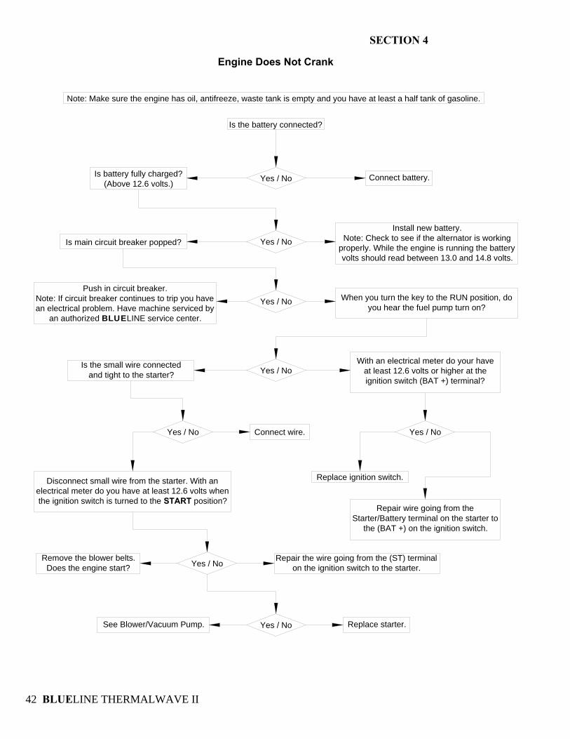
Engine Does Not Crank
Is the battery connected?
Yes / NoIs battery fully charged?(Above 12.6 volts.)
Connect battery.
Yes / NoIs main circuit breaker popped?
Install new battery.Note: Check to see if the alternator is working
properly. While the engine is running the battery volts should read between 13.0 and 14.8 volts.
Yes / NoPush in circuit breaker.
Note: If circuit breaker continues to trip you have an electrical problem. Have machine serviced by
an authorized BLUELINE service center.
When you turn the key to the RUN position, do you hear the fuel pump turn on?
Yes / NoWith an electrical meter do your have
at least 12.6 volts or higher at theignition switch (BAT +) terminal?
Is the small wire connected and tight to the starter?
Yes / No Connect wire.
Disconnect small wire from the starter. With an electrical meter do you have at least 12.6 volts when the ignition switch is turned to the START position?
Yes / No
Replace ignition switch.
Repair wire going from the Starter/Battery terminal on the starter to
the (BAT +) on the ignition switch.
Yes / NoRemove the blower belts.
Does the engine start?
Yes / No
Repair the wire going from the (ST) terminal on the ignition switch to the starter.
See Blower/Vacuum Pump. Replace starter.
Note: Make sure the engine has oil, antifreeze, waste tank is empty and you have at least a half tank of gasoline.
SECTION 4
BLUELINE THERMALWAVE II 43
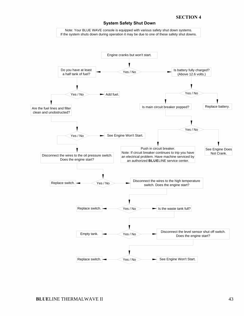
System Safety Shut DownNote: Your BLUE WAVE console is equipped with various safety shut down systems.
If the system shuts down during operation it may be due to one of these safety shut downs.
Yes / No
Replace battery.
Engine cranks but won't start.
Yes / No
Do you have at leasta half tank of fuel?
Is battery fully charged?(Above 12.6 volts.)
Yes / No Add fuel.
Are the fuel lines and filterclean and unobstructed?
Yes / No See Engine Won't Start.
Is main circuit breaker popped?
Push in circuit breaker.Note: If circuit breaker continues to trip you have an electrical problem. Have machine serviced by
an authorized BLUELINE service center.
Yes / No
See Engine DoesNot Crank.Disconnect the wires to the oil pressure switch.
Does the engine start?
Replace switch. Yes / NoDisconnect the wires to the high temperature
switch. Does the engine start?
Replace switch. Yes / No Is the waste tank full?
Yes / NoEmpty tank. Disconnect the level sensor shut off switch. Does the engine start?
Yes / NoReplace switch. See Engine Won't Start.
SECTION 4
BLUELINE THERMALWAVE II 44
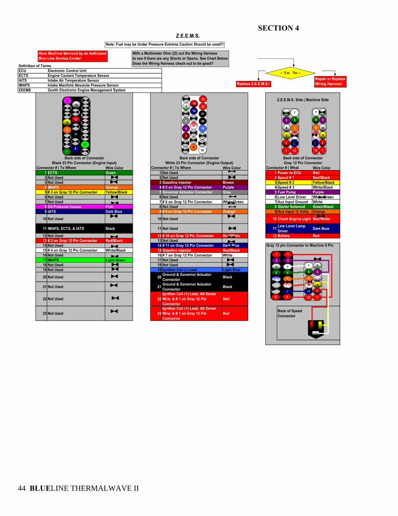
Wire Color Wire Color Wire Color1 ECTS Green 1 Not Used 1 Power to ECU Red2 Not Used 2 Not Used 2 Speed # 1 Red/Black3 Not Used 3 Gasoline Injector Brown 3 Speed # 2 Yellow/Black4 IMAPS Orange 4 # 5 on Gray 12 Pin Connector Purple 4 Speed # 3 White/Black5 # 3 on Gray 12 Pin Connector Yellow/Black 5 Governor Actuator Connector Gray 5 Fuel Pump Purple6 Not Used 6 Not Used 6 Low Level Driver White/Green7 Not Used 7 # 6 on Gray 12 Pin Connector White/Green 7 Aux Input Ground White8 Oil Pressure Sensor Pink 8 Not Used 8 Starter Solenoid Green/Black9 IATS Dark Blue 9 # 9 on Gray 12 Pin Connector Orange 9 Aux Input 12 Volts Orange
10 Not Used 10 Not Used 10 Check Engine Light Red/White
11 IMAPS, ECTS, & IATS Black 11 Not Used 11 Low Level Lamp Driver Dark Blue
12 Not Used 12 # 10 on Gray 12 Pin Connector Red/White 12 Battery Red13 # 2 on Gray 12 Pin Connector Red/Black 13 Not Used14 Not Used 14 # 11 on Gray 12 Pin Connector Dark Blue15 # 4 on Gray 12 Pin Connector White/Black 15 Gasoline Injector Red/Black16 Not Used 16 # 7 on Gray 12 Pin Connector White17 IMAPS Light Green 17 Not Used18 Not Used 18 Not Used19 Not Used 19 Ignition Coil (-) Lead Light Blue
20 Not Used 20 Ground & Governor Actuator Connector Black
21 Not Used 21 Ground & Governor Actuator Connector Black
22 Not Used 22Ignition Coil (+) Lead, Alt Sense Wire, & # 1 on Gray 12 Pin Connector
Red
23 Not Used 23Ignition Coil (+) Lead, Alt Sense Wire, & # 1 on Gray 12 Pin Connector
Red Back of Speed Connector
Gray 12 pin Connector to Machine 8 Pin
Black 23 Pin Connector (Engine Input) White 23 Pin Connector (Engine Output) Gray 12 Pin ConnectorConnector # | To Where Connector # | To Where Connector # | What
Z.E.E.M.S. Side | Machine Side
Back side of Connector Back side of Connector Back side of Connector
IMAPS Intake Manifold Absolute Pressure SensorZEEMS Zenith Electronic Engine Management System
ECTS Engine Coolant Temperature SensorIATS Intake Air Temperature Sensor
Z.E.E.M.S.
Definition of TermsECU Electronic Control Unit
Note: Fuel may be Under Pressure Extreme Caution Should be used!!!
Have Machine Serviced by an AuthoizedBlue Line Service Center!
1
2
3
4
5
6
7
8
16
17
18
19
20
21
22
23
9
10
11
12
13
14
15
1
2
3
4
5
6
7
8
16
17
18
19
20
21
22
23
9
10
11
12
13
14
15
12
11
10
9
8
7
1
2
3
4
5
6
With a Multimeter Ohm (Ω) out the Wiring Harnessto see if there are any Shorts or Opens. See Chart BelowDoes the Wiring Harness check out to be good?
←Yes No→Repair or ReplaceWiring Harness!Replace Z.E.E.M.S.!
1
2
3
4
5
6
12
11
10
9
8
7
8
7
6
5
4
3
2
1
8
7
6
5
4
3
2
1
12
11
10
9
8
7
1
2
3
4
5
6
SECTION 4
BLUELINE THERMALWAVE II 45
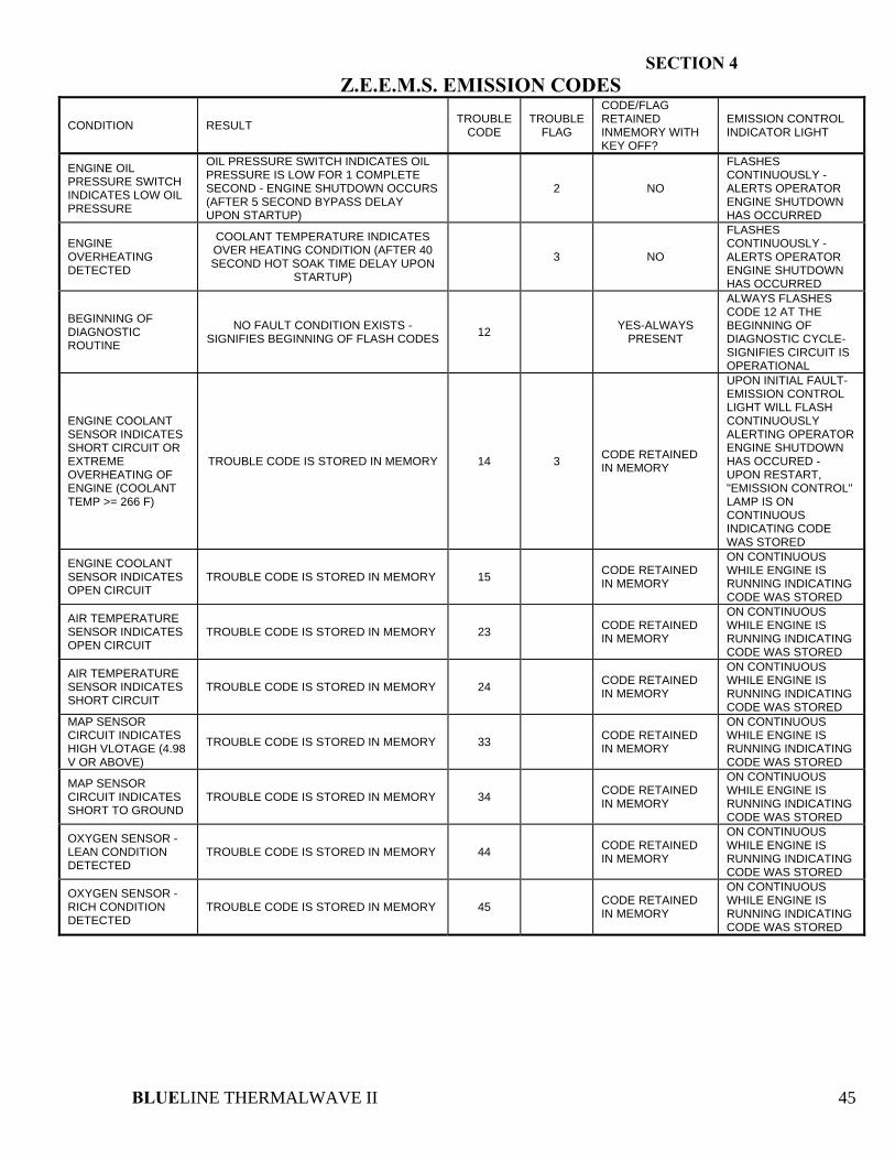
Z.E.E.M.S. EMISSION CODES
CONDITION RESULT TROUBLE CODE
TROUBLE FLAG
CODE/FLAG RETAINED INMEMORY WITH KEY OFF?
EMISSION CONTROL INDICATOR LIGHT
ENGINE OIL PRESSURE SWITCH INDICATES LOW OIL PRESSURE
OIL PRESSURE SWITCH INDICATES OIL PRESSURE IS LOW FOR 1 COMPLETE SECOND - ENGINE SHUTDOWN OCCURS (AFTER 5 SECOND BYPASS DELAY UPON STARTUP)
2 NO
FLASHES CONTINUOUSLY - ALERTS OPERATOR ENGINE SHUTDOWN HAS OCCURRED
ENGINE OVERHEATING DETECTED
COOLANT TEMPERATURE INDICATES OVER HEATING CONDITION (AFTER 40 SECOND HOT SOAK TIME DELAY UPON
STARTUP)
3 NO
FLASHES CONTINUOUSLY - ALERTS OPERATOR ENGINE SHUTDOWN HAS OCCURRED
BEGINNING OF DIAGNOSTIC ROUTINE
NO FAULT CONDITION EXISTS - SIGNIFIES BEGINNING OF FLASH CODES 12 YES-ALWAYS
PRESENT
ALWAYS FLASHES CODE 12 AT THE BEGINNING OF DIAGNOSTIC CYCLE- SIGNIFIES CIRCUIT IS OPERATIONAL
ENGINE COOLANT SENSOR INDICATES SHORT CIRCUIT OR EXTREME OVERHEATING OF ENGINE (COOLANT TEMP >= 266 F)
TROUBLE CODE IS STORED IN MEMORY 14 3 CODE RETAINED IN MEMORY
UPON INITIAL FAULT- EMISSION CONTROL LIGHT WILL FLASH CONTINUOUSLY ALERTING OPERATOR ENGINE SHUTDOWN HAS OCCURED - UPON RESTART, "EMISSION CONTROL" LAMP IS ON CONTINUOUS INDICATING CODE WAS STORED
ENGINE COOLANT SENSOR INDICATES OPEN CIRCUIT
TROUBLE CODE IS STORED IN MEMORY 15 CODE RETAINED IN MEMORY
ON CONTINUOUS WHILE ENGINE IS RUNNING INDICATING CODE WAS STORED
AIR TEMPERATURE SENSOR INDICATES OPEN CIRCUIT
TROUBLE CODE IS STORED IN MEMORY 23 CODE RETAINED IN MEMORY
ON CONTINUOUS WHILE ENGINE IS RUNNING INDICATING CODE WAS STORED
AIR TEMPERATURE SENSOR INDICATES SHORT CIRCUIT
TROUBLE CODE IS STORED IN MEMORY 24 CODE RETAINED IN MEMORY
ON CONTINUOUS WHILE ENGINE IS RUNNING INDICATING CODE WAS STORED
MAP SENSOR CIRCUIT INDICATES HIGH VLOTAGE (4.98 V OR ABOVE)
TROUBLE CODE IS STORED IN MEMORY 33 CODE RETAINED IN MEMORY
ON CONTINUOUS WHILE ENGINE IS RUNNING INDICATING CODE WAS STORED
MAP SENSOR CIRCUIT INDICATES SHORT TO GROUND
TROUBLE CODE IS STORED IN MEMORY 34 CODE RETAINED IN MEMORY
ON CONTINUOUS WHILE ENGINE IS RUNNING INDICATING CODE WAS STORED
OXYGEN SENSOR - LEAN CONDITION DETECTED
TROUBLE CODE IS STORED IN MEMORY 44 CODE RETAINED IN MEMORY
ON CONTINUOUS WHILE ENGINE IS RUNNING INDICATING CODE WAS STORED
OXYGEN SENSOR - RICH CONDITION DETECTED
TROUBLE CODE IS STORED IN MEMORY 45 CODE RETAINED IN MEMORY
ON CONTINUOUS WHILE ENGINE IS RUNNING INDICATING CODE WAS STORED
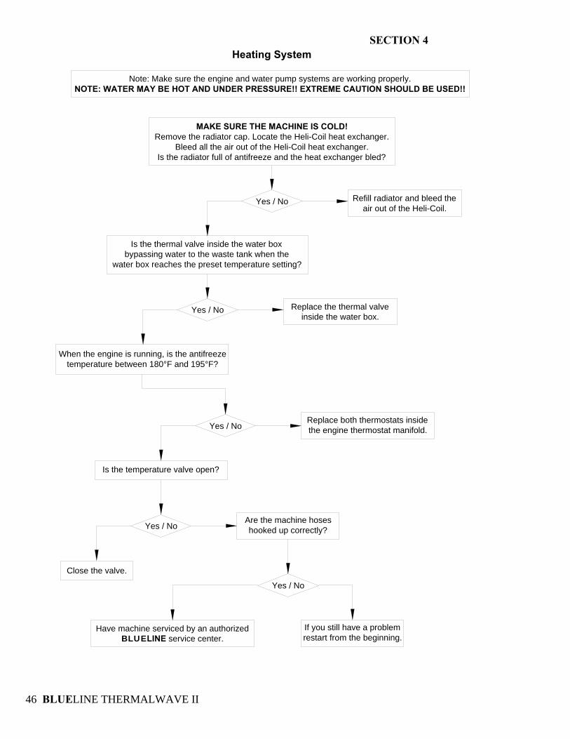
SECTION 4
BLUELINE THERMALWAVE II 46
Heating System
Yes / No
MAKE SURE THE MACHINE IS COLD!Remove the radiator cap. Locate the Heli-Coil heat exchanger.
Bleed all the air out of the Heli-Coil heat exchanger.Is the radiator full of antifreeze and the heat exchanger bled?
Is the thermal valve inside the water boxbypassing water to the waste tank when the
water box reaches the preset temperature setting?
Refill radiator and bleed theair out of the Heli-Coil.
Yes / No
Yes / No Replace the thermal valveinside the water box.
When the engine is running, is the antifreeze temperature between 180°F and 195°F?
Yes / NoReplace both thermostats insidethe engine thermostat manifold.
Is the temperature valve open?
Close the valve.
Are the machine hoseshooked up correctly?
Yes / No
Have machine serviced by an authorizedBLUELINE service center.
If you still have a problemrestart from the beginning.
Note: Make sure the engine and water pump systems are working properly.NOTE: WATER MAY BE HOT AND UNDER PRESSURE!! EXTREME CAUTION SHOULD BE USED!!
BLUELINE THERMALWAVE II 47
SECTION 5: PARTS & ACCESSORIES
9. ILLUSTRATED PARTS LISTINGS Sheet Metal 48 Engine 52 Water Transfer System 57 Vacuum-Exhaust System 64 Chemical Pumping System 68 Decals 70 Electrical Diagram 72 Optional Equipment 73 10. ACCESSORIES
Accessories 77
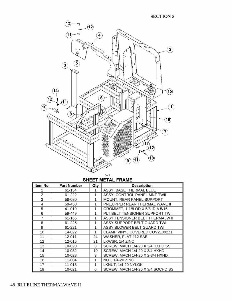
SECTION 5
BLUELINE THERMALWAVE II 48
5-1
SHEET METAL FRAME Item No. Part Number Qty Description
1 61-154 1 ASSY, BASE THERMAL BLUE 2 61-222 1 ASSY, CONTROL PANEL MNT TWII 3 58-080 1 MOUNT, REAR PANEL SUPPORT 4 59-450 1 PNL,UPPER REAR THERMAL WAVE II 5 41-019 1 GROMMET, 1-1/8 OD X 5/8 ID A 5/16 6 59-449 1 PLT,BELT TENSIONER SUPPORT TWII 7 61-165 1 ASSY,TENSIONER BELT THERMALW II 8 61-225 1 ASSY,SUPPORT BELT GUARD TWII 9 61-221 1 ASSY,BLOWER BELT GUARD TWII 10 14-022 1 CLAMP VINYL COVERED COV21092Z1 11 12-011 24 WASHER, FLAT #12 SAE 12 12-015 21 LKWSR, 1/4 ZINC 13 10-020 3 SCREW, MACH 1/4-20 X 3/4 HXHD SS 14 10-032 10 SCREW, MACH 1/4-20 X 3/4 HXHD 15 10-028 3 SCREW, MACH 1/4-20 X 2-3/4 HXHD 16 11-004 1 NUT, 1/4-20 ZINC 17 11-013 1 LKNUT, 1/4-20 NYLOK 18 10-021 6 SCREW, MACH 1/4-20 X 3/4 SOCHD SS
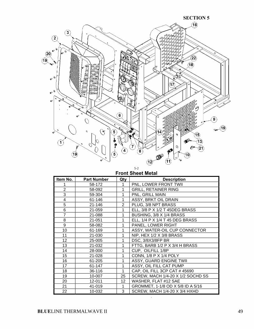
SECTION 5
BLUELINE THERMALWAVE II 49
5-2
Front Sheet Metal Item No. Part Number Qty Description
1 58-172 1 PNL, LOWER FRONT TWII 2 58-092 1 GRILL, RETAINER RING 3 59-304 1 PNL, GRILL MAIN 4 61-146 1 ASSY, BRKT OIL DRAIN 5 21-146 2 PLUG, 3/8 NPT BRASS 6 21-059 1 ELL, 3/8 P X 1/2 T 45DEG BRASS 7 21-088 1 BUSHING, 3/8 X 1/4 BRASS 8 21-051 1 ELL, 1/4 P X 1/4 T 45 DEG BRASS 9 58-082 1 PANEL, LOWER RIGHT 10 61-169 1 ASSY, WATER-OIL CUP CONNECTOR 11 21-030 1 NIP, HEX 1/2 X 3/8 BRASS 12 25-005 1 DSC, 3/8X3/8FP BR 13 21-032 1 FTTG, BARB 1/2 P X 3/4 H BRASS 14 28-000 1 CUP, OILFILL 1/8P 15 21-028 1 CONN, 1/8 P X 1/4 POLY 16 61-205 1 ASSY, GUARD ENGINE TWII 17 61-147 1 ASSY, OIL FILL CAT PUMP 18 36-116 1 CAP, OIL FILL 3CP CAT # 45690 19 10-007 25 SCREW, MACH 1/4-20 X 1/2 SOCHD SS 20 12-011 12 WASHER, FLAT #12 SAE 21 41-019 1 GROMMET, 1-1/8 OD X 5/8 ID A 5/16 22 10-032 3 SCREW, MACH 1/4-20 X 3/4 HXHD
.
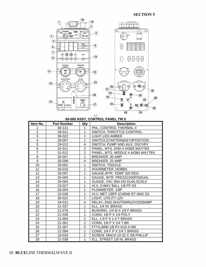
SECTION 5
BLUELINE THERMALWAVE II 50
5-3
69-088 ASSY, CONTROL PANEL TW II Item No. Part Number Qty Description
1 58-131 1 PNL, CONTROL THERMAL II 2 29-011 1 SWITCH, THROTTLE CONTROL 3 30-022 1 LIGHT,LED AMBER 4 29-007 1 SWITCH,STARTER&KEY3POSITION 5 29-012 4 SWITCH, PUMP AND AUX. DSCVRY 6 31-011 2 PANEL, MTG. END # 44383 WAYTEK 7 31-012 2 PANEL, MTG. MIDDLE # 44384 WAYTEK 8 30-007 1 BREAKER, 30 AMP 9 30-008 4 BREAKER, 20 AMP 10 29-001 1 SWITCH, TOGGLE 11 26-010 1 HOURMETER, HOBBS 12 26-007 1 GAUGE,WTR. TEMP 320 DEG 13 26-005 1 GAUGE, WTR. PRESS1500PSIDUAL 14 26-004 1 GUAGE, VAC 30in.HG DUALSCALE 15 23-027 1 VLV, 3-WAY BALL 1/8 FP SS 16 26-003 1 FLOWMETER, 1/8P 17 23-028 1 VLV, MET 1/8FP (CHEM) RT ANG SS 18 30-021 1 LIGHT, UTILITY 12V 19 34-010 4 RELAY, ENG.SHUTDWN12V20/30AMP 20 21-037 1 ELL, 1/4 IN. BRASS 21 21-076 1 BUSHING, 1/4 M X 1/8 F BRASS 22 21-028 1 CONN, 1/8 P X 1/4 POLY 23 21-054 2 ELL, 1-8 P X 1-4 T BRASS 24 21-001 2 CONN, 1/8 P X 1/4 T BR 25 21-007 3 FTTG,BRB 1/8 PX 5/16 H BR 26 21-004 1 CONN, 1/4 F P X 1/4 T BRASS 27 10-033 2 SCREW, MACH 10-32 X 3/8 PHILLIP 28 21-038 1 ELL, STREET 1/8 IN. BRASS
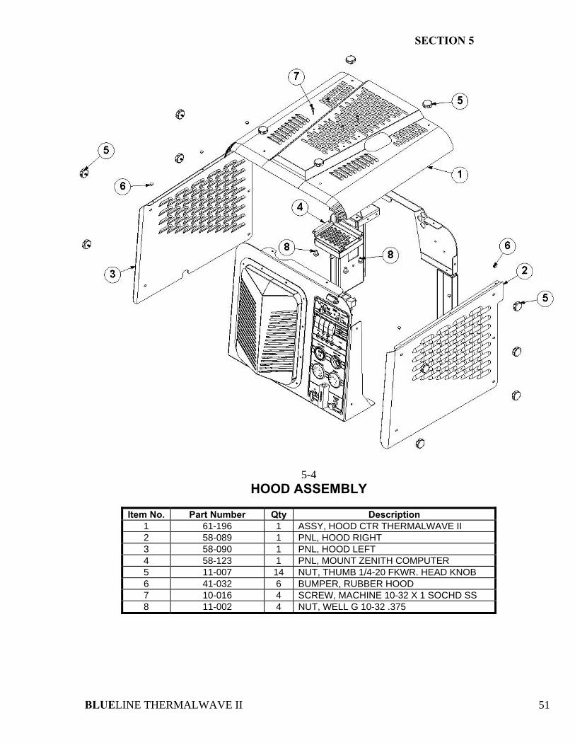
SECTION 5
BLUELINE THERMALWAVE II 51
5-4 HOOD ASSEMBLY
Item No. Part Number Qty Description
1 61-196 1 ASSY, HOOD CTR THERMALWAVE II 2 58-089 1 PNL, HOOD RIGHT 3 58-090 1 PNL, HOOD LEFT 4 58-123 1 PNL, MOUNT ZENITH COMPUTER 5 11-007 14 NUT, THUMB 1/4-20 FKWR. HEAD KNOB 6 41-032 6 BUMPER, RUBBER HOOD 7 10-016 4 SCREW, MACHINE 10-32 X 1 SOCHD SS 8 11-002 4 NUT, WELL G 10-32 .375
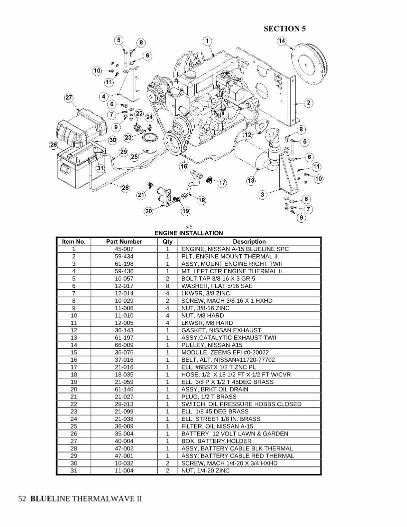
SECTION 5
BLUELINE THERMALWAVE II 52
5-5
ENGINE INSTALLATION Item No. Part Number Qty Description
1 45-007 1 ENGINE, NISSAN A-15 BLUELINE SPC 2 59-434 1 PLT, ENGINE MOUNT THERMAL II 3 61-198 1 ASSY, MOUNT ENGINE RIGHT TWII 4 59-436 1 MT, LEFT CTR ENGINE THERMAL II 5 10-057 2 BOLT,TAP 3/8-16 X 3 GR 5 6 12-017 8 WASHER, FLAT 5/16 SAE 7 12-014 4 LKWSR, 3/8 ZINC 8 10-029 2 SCREW, MACH 3/8-16 X 1 HXHD 9 11-006 4 NUT, 3/8-16 ZINC 10 11-010 4 NUT, M8 HARD 11 12-005 4 LKWSR, M8 HARD 12 36-143 1 GASKET, NISSAN EXHAUST 13 61-197 1 ASSY,CATALYTIC EXHAUST TWII 14 66-009 1 PULLEY, NISSAN A15 15 36-076 1 MODULE, ZEEMS EFI #0-20022 16 37-016 1 BELT, ALT. NISSAN#11720-77702 17 21-016 1 ELL, #6BSTX 1/2 T ZNC PL 18 18-035 1 HOSE, 1/2 X 18 1/2 FT X 1/2 FT W/CVR 19 21-059 1 ELL, 3/8 P X 1/2 T 45DEG BRASS 20 61-146 1 ASSY, BRKT OIL DRAIN 21 21-027 1 PLUG, 1/2 T BRASS 22 29-013 1 SWITCH, OIL PRESSURE HOBBS CLOSED 23 21-099 1 ELL, 1/8 45 DEG BRASS 24 21-038 1 ELL, STREET 1/8 IN. BRASS 25 36-009 1 FILTER, OIL NISSAN A-15 26 35-004 1 BATTERY, 12 VOLT LAWN & GARDEN 27 40-004 1 BOX, BATTERY HOLDER 28 47-002 1 ASSY, BATTERY CABLE BLK THERMAL 29 47-001 1 ASSY, BATTERY CABLE RED THERMAL 30 10-032 2 SCREW, MACH 1/4-20 X 3/4 HXHD 31 11-004 2 NUT, 1/4-20 ZINC
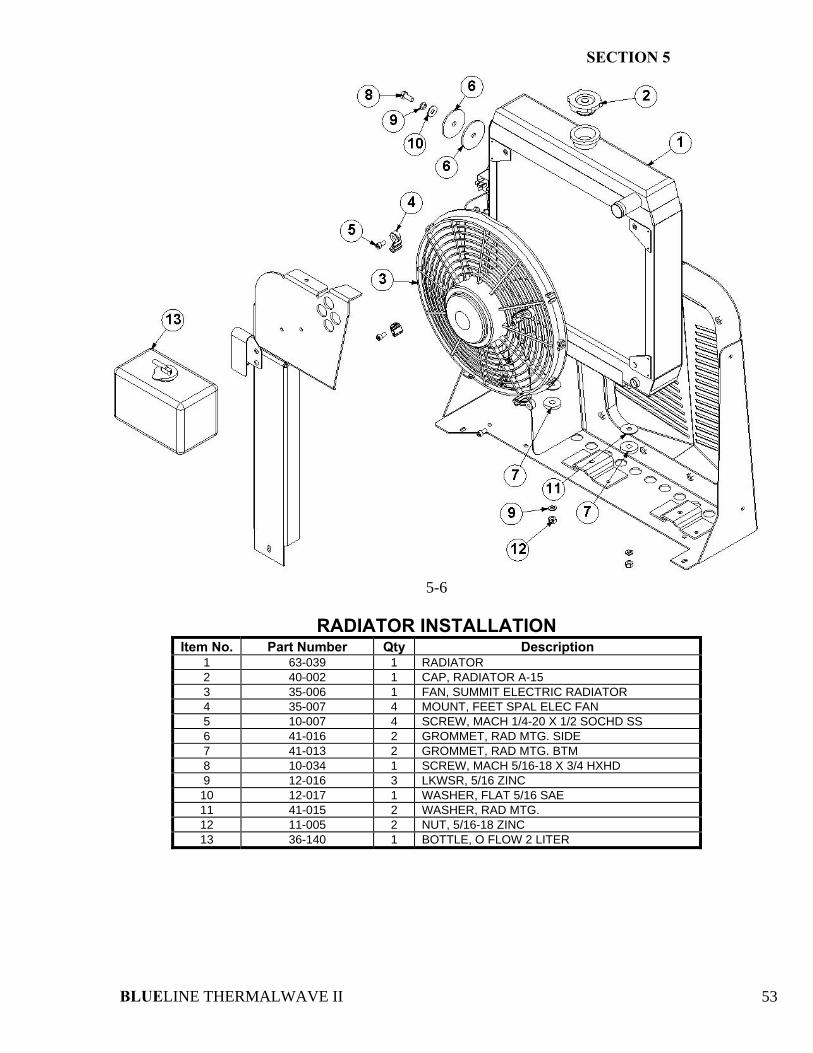
SECTION 5
BLUELINE THERMALWAVE II 53
5-6
RADIATOR INSTALLATION
Item No. Part Number Qty Description 1 63-039 1 RADIATOR 2 40-002 1 CAP, RADIATOR A-15 3 35-006 1 FAN, SUMMIT ELECTRIC RADIATOR 4 35-007 4 MOUNT, FEET SPAL ELEC FAN 5 10-007 4 SCREW, MACH 1/4-20 X 1/2 SOCHD SS 6 41-016 2 GROMMET, RAD MTG. SIDE 7 41-013 2 GROMMET, RAD MTG. BTM 8 10-034 1 SCREW, MACH 5/16-18 X 3/4 HXHD 9 12-016 3 LKWSR, 5/16 ZINC 10 12-017 1 WASHER, FLAT 5/16 SAE 11 41-015 2 WASHER, RAD MTG. 12 11-005 2 NUT, 5/16-18 ZINC 13 36-140 1 BOTTLE, O FLOW 2 LITER
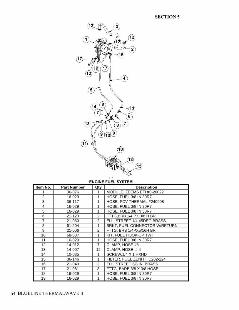
SECTION 5
BLUELINE THERMALWAVE II 54
5-7
ENGINE FUEL SYSTEM Item No. Part Number Qty Description
1 36-076 1 MODULE, ZEEMS EFI #0-20022 2 16-029 1 HOSE, FUEL 3/8 IN 30R7 3 36-117 1 HOSE, PCV THERMAL #249908 4 16-029 1 HOSE, FUEL 3/8 IN 30R7 5 16-029 1 HOSE, FUEL 3/8 IN 30R7 6 21-123 2 FTTG,BRB 1/4 PX 3/8 H BR 7 21-060 2 ELL, STREET 1/4 45DEG BRASS 8 61-204 1 BRKT, FUEL CONNECTOR W/RETURN 9 21-006 2 FTTG, BRB 1/4PX5/16H BR 10 68-087 1 KIT, FUEL HOOK-UP TWII 11 16-029 1 HOSE, FUEL 3/8 IN 30R7 12 14-012 7 CLAMP, HOSE #8 13 14-007 12 CLAMP, HOSE # 4 14 10-035 1 SCREW,1/4 X 1 HXHD 15 36-146 1 FILTER, FUEL ZENITH C282-224 16 21-040 2 ELL, STREET 3/8 IN. BRASS 17 21-081 3 FTTG, BARB 3/8 X 3/8 HOSE 18 16-029 1 HOSE, FUEL 3/8 IN 30R7 19 16-029 1 HOSE, FUEL 3/8 IN 30R7
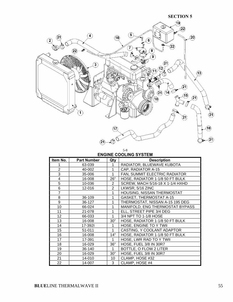
SECTION 5
BLUELINE THERMALWAVE II 55
5-8
ENGINE COOLING SYSTEM Item No. Part Number Qty Description
1 63-039 1 RADIATOR, BLUEWAVE KUBOTA 2 40-002 1 CAP, RADIATOR A-15 3 35-006 1 FAN, SUMMIT ELECTRIC RADIATOR 4 16-008 26" HOSE, RADIATOR 1-1/8 50 FT BULK 5 10-036 2 SCREW, MACH 5/16-18 X 1-1/4 HXHD 6 12-016 2 LKWSR, 5/16 ZINC 7 1 HOUSING, NISSAN THERMOSTAT 8 36-109 1 GASKET, THERMOSTAT A-15 9 36-127 1 THERMOSTAT, NISSAN A-15 195 DEG 10 66-024 1 MANIFOLD, ENG THERMOSTAT BYPASS 11 21-078 1 ELL, STREET PIPE 3/4 DEG 12 66-033 1 3/4 NPT TO 1-1/8 HOSE 13 16-008 30" HOSE, RADIATOR 1-1/8 50 FT BULK 14 17-392I 1 HOSE, ENGINE TO Y TWII 15 51-011 1 CASTING, Y COOLANT ADAPTOR 16 16-008 14" HOSE, RADIATOR 1-1/8 50 FT BULK 17 17-391 1 HOSE, LWR RAD TO Y TWII 18 16-029 36" HOSE, FUEL 3/8 IN 30R7 19 36-140 1 BOTTLE, O FLOW 2 LITER 20 16-029 30" HOSE, FUEL 3/8 IN 30R7 21 14-010 10 CLAMP, HOSE #32 22 14-007 3 CLAMP, HOSE #4
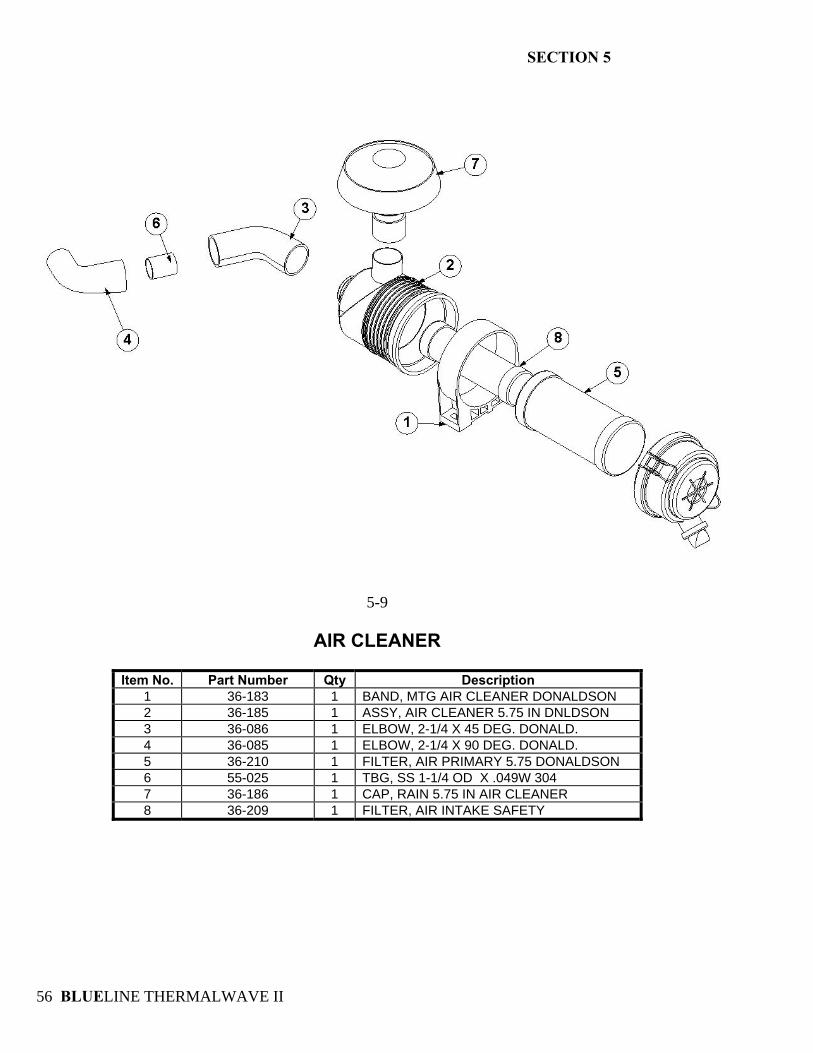
SECTION 5
BLUELINE THERMALWAVE II 56
5-9
AIR CLEANER
Item No. Part Number Qty Description
1 36-183 1 BAND, MTG AIR CLEANER DONALDSON 2 36-185 1 ASSY, AIR CLEANER 5.75 IN DNLDSON 3 36-086 1 ELBOW, 2-1/4 X 45 DEG. DONALD. 4 36-085 1 ELBOW, 2-1/4 X 90 DEG. DONALD. 5 36-210 1 FILTER, AIR PRIMARY 5.75 DONALDSON 6 55-025 1 TBG, SS 1-1/4 OD X .049W 304 7 36-186 1 CAP, RAIN 5.75 IN AIR CLEANER 8 36-209 1 FILTER, AIR INTAKE SAFETY
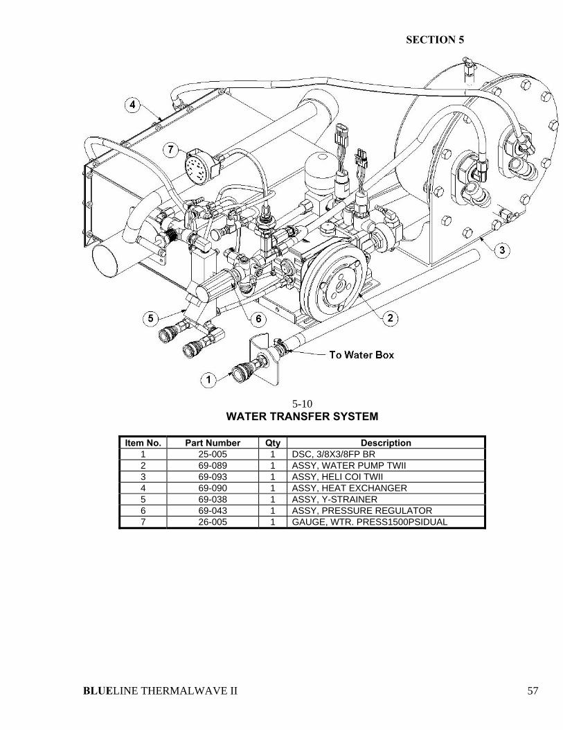
SECTION 5
BLUELINE THERMALWAVE II 57
5-10 WATER TRANSFER SYSTEM
Item No. Part Number Qty Description
1 25-005 1 DSC, 3/8X3/8FP BR 2 69-089 1 ASSY, WATER PUMP TWII 3 69-093 1 ASSY, HELI COI TWII 4 69-090 1 ASSY, HEAT EXCHANGER 5 69-038 1 ASSY, Y-STRAINER 6 69-043 1 ASSY, PRESSURE REGULATOR 7 26-005 1 GAUGE, WTR. PRESS1500PSIDUAL
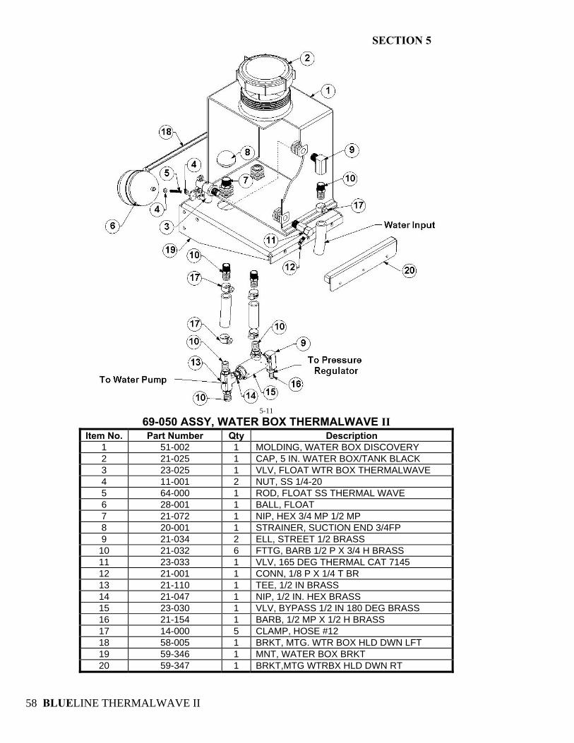
SECTION 5
BLUELINE THERMALWAVE II 58
5-11
69-050 ASSY, WATER BOX THERMALWAVE II Item No. Part Number Qty Description
1 51-002 1 MOLDING, WATER BOX DISCOVERY 2 21-025 1 CAP, 5 IN. WATER BOX/TANK BLACK 3 23-025 1 VLV, FLOAT WTR BOX THERMALWAVE 4 11-001 2 NUT, SS 1/4-20 5 64-000 1 ROD, FLOAT SS THERMAL WAVE 6 28-001 1 BALL, FLOAT 7 21-072 1 NIP, HEX 3/4 MP 1/2 MP 8 20-001 1 STRAINER, SUCTION END 3/4FP 9 21-034 2 ELL, STREET 1/2 BRASS 10 21-032 6 FTTG, BARB 1/2 P X 3/4 H BRASS 11 23-033 1 VLV, 165 DEG THERMAL CAT 7145 12 21-001 1 CONN, 1/8 P X 1/4 T BR 13 21-110 1 TEE, 1/2 IN BRASS 14 21-047 1 NIP, 1/2 IN. HEX BRASS 15 23-030 1 VLV, BYPASS 1/2 IN 180 DEG BRASS 16 21-154 1 BARB, 1/2 MP X 1/2 H BRASS 17 14-000 5 CLAMP, HOSE #12 18 58-005 1 BRKT, MTG. WTR BOX HLD DWN LFT 19 59-346 1 MNT, WATER BOX BRKT 20 59-347 1 BRKT,MTG WTRBX HLD DWN RT
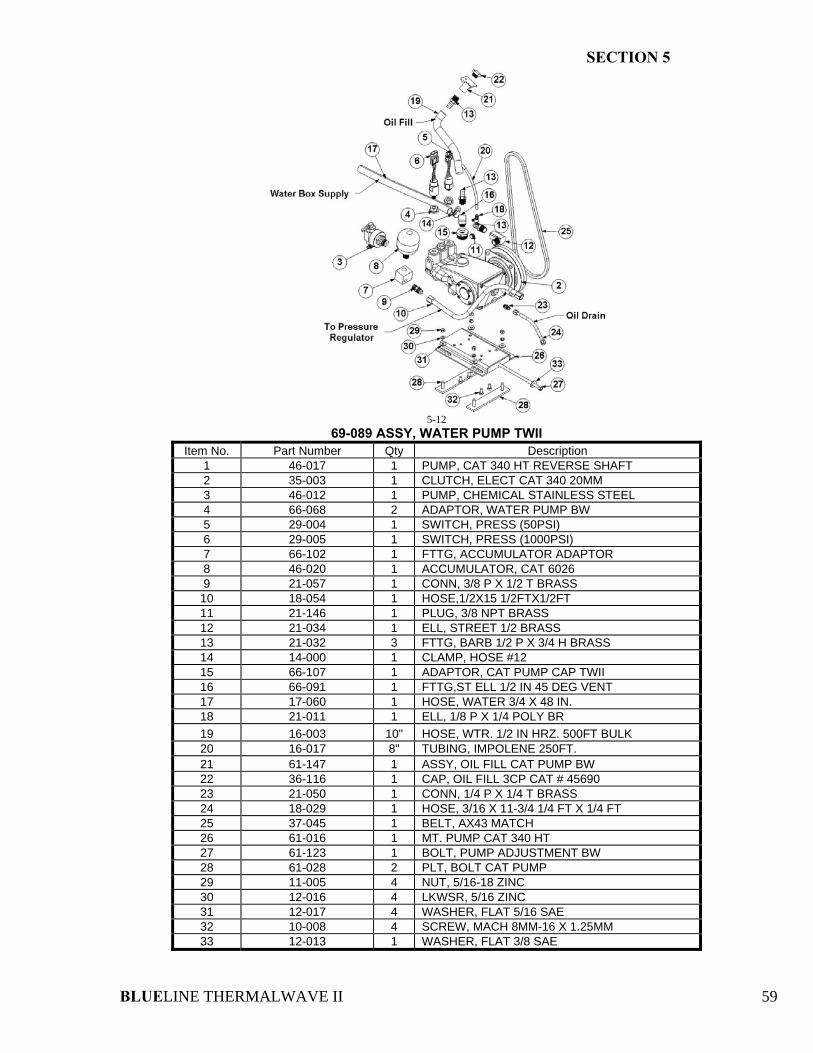
SECTION 5
BLUELINE THERMALWAVE II 59
5-12
69-089 ASSY, WATER PUMP TWII Item No. Part Number Qty Description
1 46-017 1 PUMP, CAT 340 HT REVERSE SHAFT 2 35-003 1 CLUTCH, ELECT CAT 340 20MM 3 46-012 1 PUMP, CHEMICAL STAINLESS STEEL 4 66-068 2 ADAPTOR, WATER PUMP BW 5 29-004 1 SWITCH, PRESS (50PSI) 6 29-005 1 SWITCH, PRESS (1000PSI) 7 66-102 1 FTTG, ACCUMULATOR ADAPTOR 8 46-020 1 ACCUMULATOR, CAT 6026 9 21-057 1 CONN, 3/8 P X 1/2 T BRASS 10 18-054 1 HOSE,1/2X15 1/2FTX1/2FT 11 21-146 1 PLUG, 3/8 NPT BRASS 12 21-034 1 ELL, STREET 1/2 BRASS 13 21-032 3 FTTG, BARB 1/2 P X 3/4 H BRASS 14 14-000 1 CLAMP, HOSE #12 15 66-107 1 ADAPTOR, CAT PUMP CAP TWII 16 66-091 1 FTTG,ST ELL 1/2 IN 45 DEG VENT 17 17-060 1 HOSE, WATER 3/4 X 48 IN. 18 21-011 1 ELL, 1/8 P X 1/4 POLY BR 19 16-003 10" HOSE, WTR. 1/2 IN HRZ. 500FT BULK 20 16-017 8" TUBING, IMPOLENE 250FT. 21 61-147 1 ASSY, OIL FILL CAT PUMP BW 22 36-116 1 CAP, OIL FILL 3CP CAT # 45690 23 21-050 1 CONN, 1/4 P X 1/4 T BRASS 24 18-029 1 HOSE, 3/16 X 11-3/4 1/4 FT X 1/4 FT 25 37-045 1 BELT, AX43 MATCH 26 61-016 1 MT. PUMP CAT 340 HT 27 61-123 1 BOLT, PUMP ADJUSTMENT BW 28 61-028 2 PLT, BOLT CAT PUMP 29 11-005 4 NUT, 5/16-18 ZINC 30 12-016 4 LKWSR, 5/16 ZINC 31 12-017 4 WASHER, FLAT 5/16 SAE 32 10-008 4 SCREW, MACH 8MM-16 X 1.25MM 33 12-013 1 WASHER, FLAT 3/8 SAE
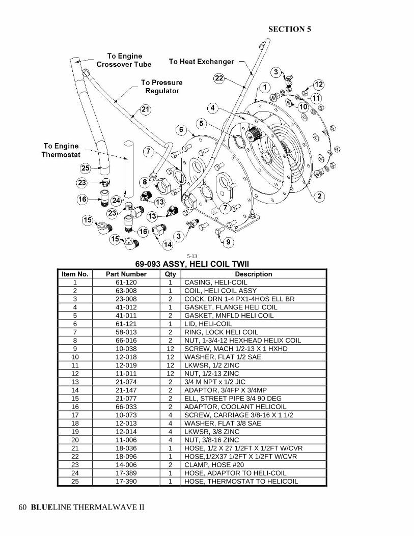
SECTION 5
BLUELINE THERMALWAVE II 60
5-13
69-093 ASSY, HELI COIL TWII Item No. Part Number Qty Description
1 61-120 1 CASING, HELI-COIL 2 63-008 1 COIL, HELI COIL ASSY 3 23-008 2 COCK, DRN 1-4 PX1-4HOS ELL BR 4 41-012 1 GASKET, FLANGE HELI COIL 5 41-011 2 GASKET, MNFLD HELI COIL 6 61-121 1 LID, HELI-COIL 7 58-013 2 RING, LOCK HELI COIL 8 66-016 2 NUT, 1-3/4-12 HEXHEAD HELIX COIL 9 10-038 12 SCREW, MACH 1/2-13 X 1 HXHD 10 12-018 12 WASHER, FLAT 1/2 SAE 11 12-019 12 LKWSR, 1/2 ZINC 12 11-011 12 NUT, 1/2-13 ZINC 13 21-074 2 3/4 M NPT x 1/2 JIC 14 21-147 2 ADAPTOR, 3/4FP X 3/4MP 15 21-077 2 ELL, STREET PIPE 3/4 90 DEG 16 66-033 2 ADAPTOR, COOLANT HELICOIL 17 10-073 4 SCREW, CARRIAGE 3/8-16 X 1 1/2 18 12-013 4 WASHER, FLAT 3/8 SAE 19 12-014 4 LKWSR, 3/8 ZINC 20 11-006 4 NUT, 3/8-16 ZINC 21 18-036 1 HOSE, 1/2 X 27 1/2FT X 1/2FT W/CVR 22 18-096 1 HOSE,1/2X37 1/2FT X 1/2FT W/CVR 23 14-006 2 CLAMP, HOSE #20 24 17-389 1 HOSE, ADAPTOR TO HELI-COIL 25 17-390 1 HOSE, THERMOSTAT TO HELICOIL
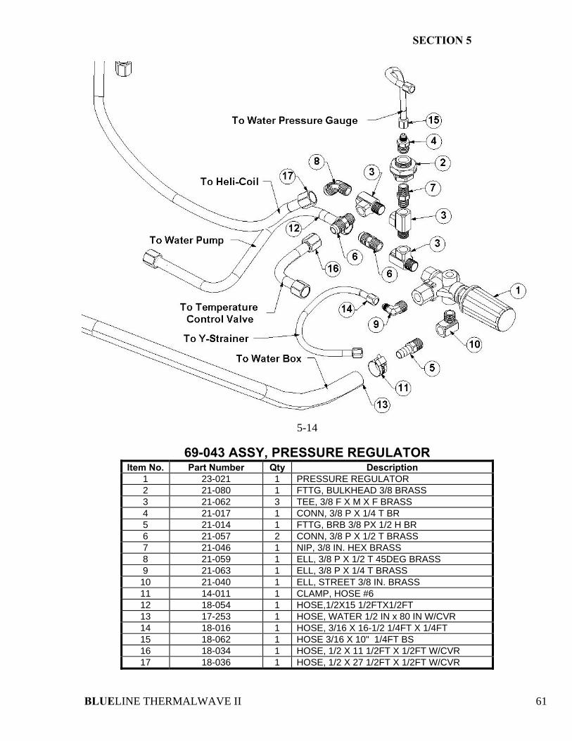
SECTION 5
BLUELINE THERMALWAVE II 61
5-14
69-043 ASSY, PRESSURE REGULATOR
Item No. Part Number Qty Description 1 23-021 1 PRESSURE REGULATOR 2 21-080 1 FTTG, BULKHEAD 3/8 BRASS 3 21-062 3 TEE, 3/8 F X M X F BRASS 4 21-017 1 CONN, 3/8 P X 1/4 T BR 5 21-014 1 FTTG, BRB 3/8 PX 1/2 H BR 6 21-057 2 CONN, 3/8 P X 1/2 T BRASS 7 21-046 1 NIP, 3/8 IN. HEX BRASS 8 21-059 1 ELL, 3/8 P X 1/2 T 45DEG BRASS 9 21-063 1 ELL, 3/8 P X 1/4 T BRASS 10 21-040 1 ELL, STREET 3/8 IN. BRASS 11 14-011 1 CLAMP, HOSE #6 12 18-054 1 HOSE,1/2X15 1/2FTX1/2FT 13 17-253 1 HOSE, WATER 1/2 IN x 80 IN W/CVR 14 18-016 1 HOSE, 3/16 X 16-1/2 1/4FT X 1/4FT 15 18-062 1 HOSE 3/16 X 10" 1/4FT BS 16 18-034 1 HOSE, 1/2 X 11 1/2FT X 1/2FT W/CVR 17 18-036 1 HOSE, 1/2 X 27 1/2FT X 1/2FT W/CVR
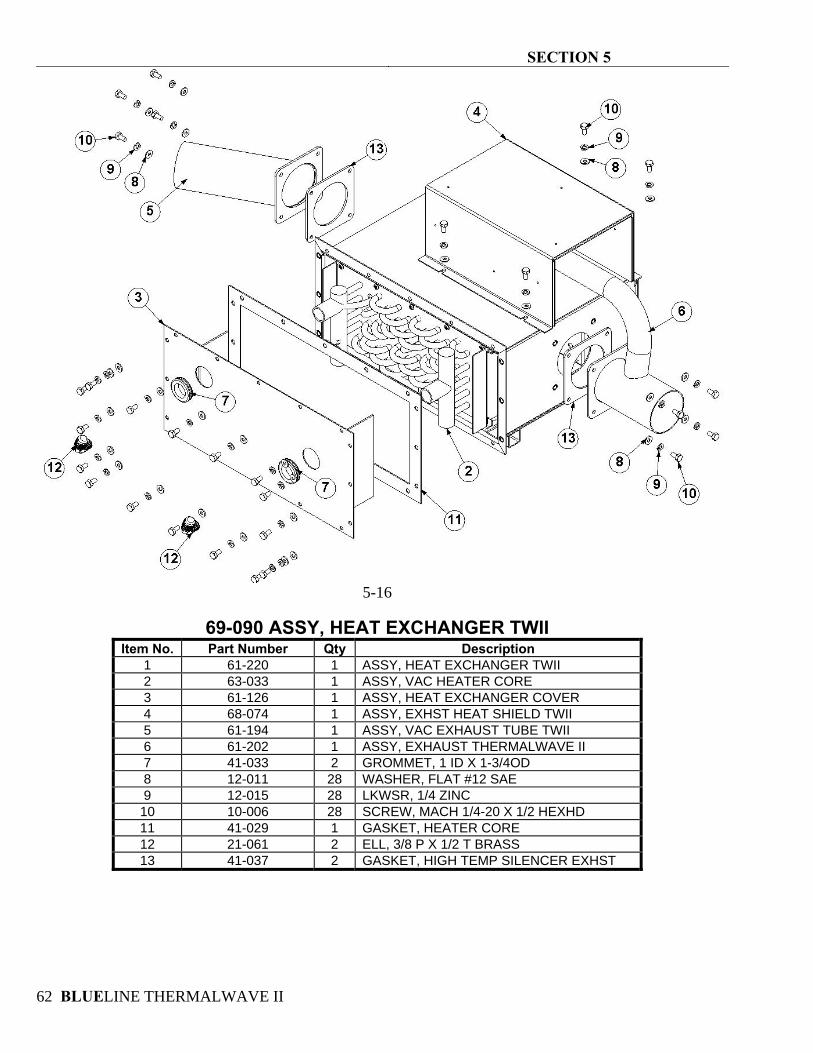
SECTION 5
BLUELINE THERMALWAVE II 62
5-16
69-090 ASSY, HEAT EXCHANGER TWII
Item No. Part Number Qty Description 1 61-220 1 ASSY, HEAT EXCHANGER TWII 2 63-033 1 ASSY, VAC HEATER CORE 3 61-126 1 ASSY, HEAT EXCHANGER COVER 4 68-074 1 ASSY, EXHST HEAT SHIELD TWII 5 61-194 1 ASSY, VAC EXHAUST TUBE TWII 6 61-202 1 ASSY, EXHAUST THERMALWAVE II 7 41-033 2 GROMMET, 1 ID X 1-3/4OD 8 12-011 28 WASHER, FLAT #12 SAE 9 12-015 28 LKWSR, 1/4 ZINC 10 10-006 28 SCREW, MACH 1/4-20 X 1/2 HEXHD 11 41-029 1 GASKET, HEATER CORE 12 21-061 2 ELL, 3/8 P X 1/2 T BRASS 13 41-037 2 GASKET, HIGH TEMP SILENCER EXHST
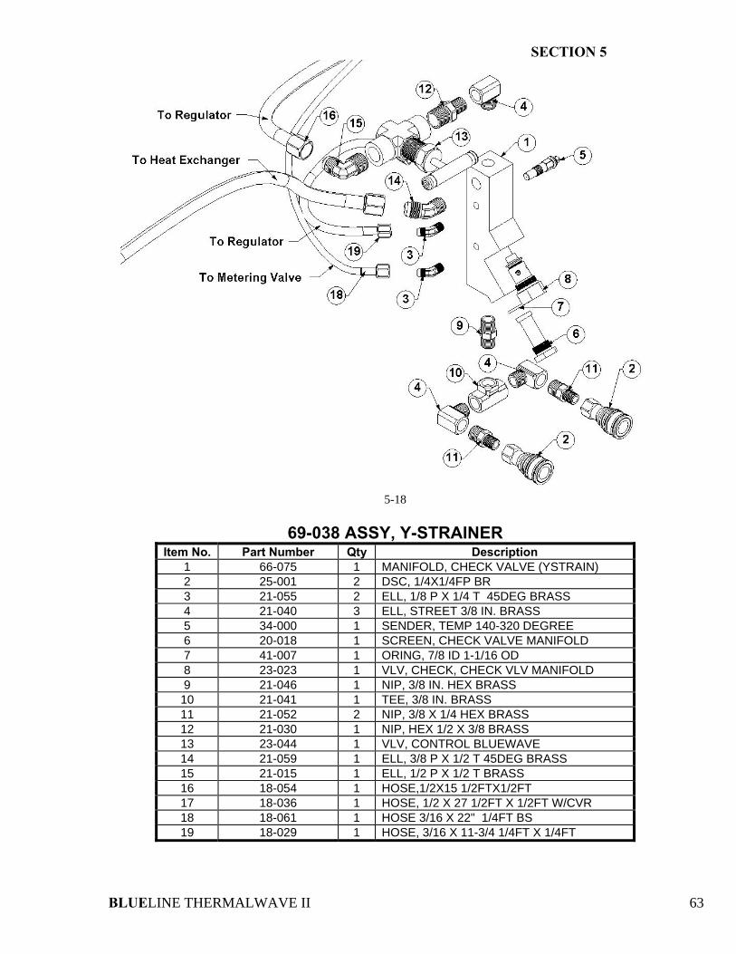
SECTION 5
BLUELINE THERMALWAVE II 63
5-18
69-038 ASSY, Y-STRAINER
Item No. Part Number Qty Description 1 66-075 1 MANIFOLD, CHECK VALVE (YSTRAIN) 2 25-001 2 DSC, 1/4X1/4FP BR 3 21-055 2 ELL, 1/8 P X 1/4 T 45DEG BRASS 4 21-040 3 ELL, STREET 3/8 IN. BRASS 5 34-000 1 SENDER, TEMP 140-320 DEGREE 6 20-018 1 SCREEN, CHECK VALVE MANIFOLD 7 41-007 1 ORING, 7/8 ID 1-1/16 OD 8 23-023 1 VLV, CHECK, CHECK VLV MANIFOLD 9 21-046 1 NIP, 3/8 IN. HEX BRASS 10 21-041 1 TEE, 3/8 IN. BRASS 11 21-052 2 NIP, 3/8 X 1/4 HEX BRASS 12 21-030 1 NIP, HEX 1/2 X 3/8 BRASS 13 23-044 1 VLV, CONTROL BLUEWAVE 14 21-059 1 ELL, 3/8 P X 1/2 T 45DEG BRASS 15 21-015 1 ELL, 1/2 P X 1/2 T BRASS 16 18-054 1 HOSE,1/2X15 1/2FTX1/2FT 17 18-036 1 HOSE, 1/2 X 27 1/2FT X 1/2FT W/CVR 18 18-061 1 HOSE 3/16 X 22" 1/4FT BS 19 18-029 1 HOSE, 3/16 X 11-3/4 1/4FT X 1/4FT
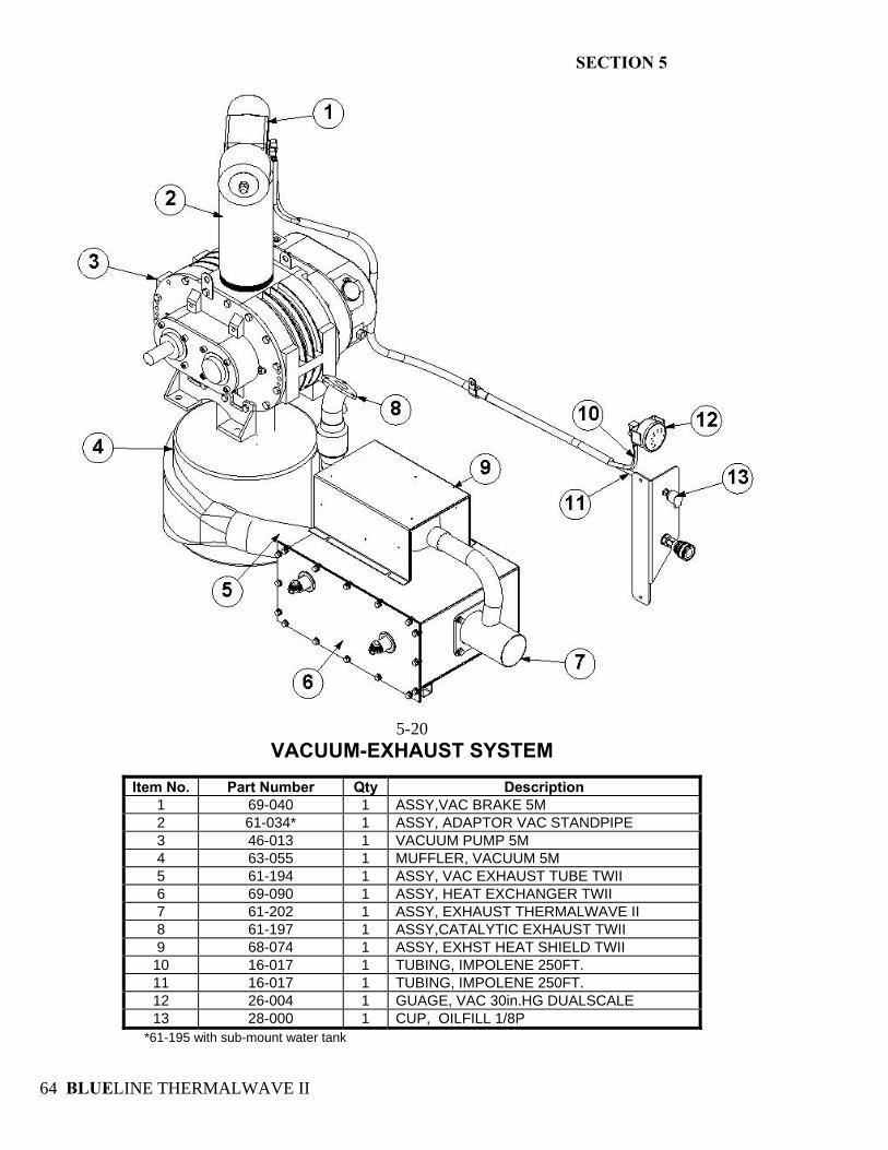
SECTION 5
BLUELINE THERMALWAVE II 64
5-20
VACUUM-EXHAUST SYSTEM
Item No. Part Number Qty Description 1 69-040 1 ASSY,VAC BRAKE 5M 2 61-034* 1 ASSY, ADAPTOR VAC STANDPIPE 3 46-013 1 VACUUM PUMP 5M 4 63-055 1 MUFFLER, VACUUM 5M 5 61-194 1 ASSY, VAC EXHAUST TUBE TWII 6 69-090 1 ASSY, HEAT EXCHANGER TWII 7 61-202 1 ASSY, EXHAUST THERMALWAVE II 8 61-197 1 ASSY,CATALYTIC EXHAUST TWII 9 68-074 1 ASSY, EXHST HEAT SHIELD TWII 10 16-017 1 TUBING, IMPOLENE 250FT. 11 16-017 1 TUBING, IMPOLENE 250FT. 12 26-004 1 GUAGE, VAC 30in.HG DUALSCALE 13 28-000 1 CUP, OILFILL 1/8P
*61-195 with sub-mount water tank
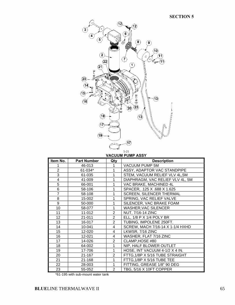
SECTION 5
BLUELINE THERMALWAVE II 65
5-21
VACUUM PUMP ASSY Item No. Part Number Qty Description
1 46-013 1 VACUUM PUMP 5M 2 61-034* 1 ASSY, ADAPTOR VAC STANDPIPE 3 61-035 1 STEM, VACUUM RELIEF VLV 4L,5M 4 41-009 1 DIAPHRAGM, VAC RELIEF VLV 4L, 5M 5 66-001 1 VAC BRAKE, MACHINED 4L 6 58-106 1 SPACER, .125 X .688 X 1.625 7 58-108 1 SCREEN, SILENCER THERMAL 8 15-002 1 SPRING, VAC RELIEF VALVE 9 50-000 1 SILENCER, VAC BRAKE FOAM 10 58-077 1 WASHER,VAC SILENCER 11 11-012 2 NUT, 7/16-14 ZINC 12 21-011 2 ELL, 1/8 P X 1/4 POLY BR 13 16-017 2 TUBING, IMPOLENE 250FT. 14 10-041 4 SCREW, MACH 7/16-14 X 1-1/4 HXHD 15 12-020 4 LKWSR, 7/16 ZINC 16 12-021 4 WASHER, FLAT 7/16 ZINC 17 14-026 2 CLAMP,HOSE #80 18 64-002 1 NIP, HALF BLOWER OUTLET 19 17-706 1 HOSE, INT VACUUM 4-1/2 X 4 IN. 20 21-167 2 FTTG,1/8P X 5/16 TUBE STRAIGHT 21 21-168 1 FTTG,1/8P X 5/16 TUBE TEE 22 28-003 1 FITTING, GREASE 1/8" 90 DEG 23 55-052 2 TBG, 5/16 X 10FT COPPER *61-195 with sub-mount water tank
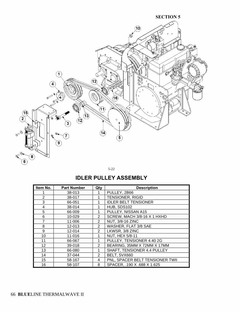
SECTION 5
BLUELINE THERMALWAVE II 66
5-22
IDLER PULLEY ASSEMBLY
Item No. Part Number Qty Description 1 38-013 1 PULLEY, 2B66 2 38-017 1 TENSIONER, RIGID 3 66-051 1 IDLER BELT TENSIONER 4 38-014 1 HUB, SDS102 5 66-009 1 PULLEY, NISSAN A15 6 10-029 2 SCREW, MACH 3/8-16 X 1 HXHD 7 11-006 2 NUT, 3/8-16 ZINC 8 12-013 2 WASHER, FLAT 3/8 SAE 9 12-014 2 LKWSR, 3/8 ZINC 10 11-016 1 NUT, HEX 5/8-11 11 66-067 1 PULLEY, TENSIONER 4.40 2G 12 39-018 2 BEARING, 35MM X 72MM X 17MM 13 66-080 1 SHAFT, TENSIONER 4.4 PULLEY 14 37-044 2 BELT, 5VX660 15 58-167 4 PNL, SPACER BELT TENSIONER TWII 16 58-107 8 SPACER, .190 X .688 X 1.625
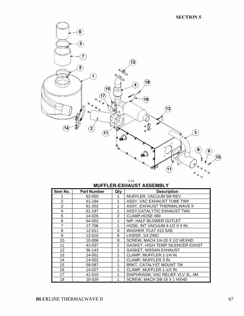
SECTION 5
BLUELINE THERMALWAVE II 67
5-24
MUFFLER-EXHAUST ASSEMBLY Item No. Part Number Qty Description
1 63-055 1 MUFFLER, VACUUM 5M REV 2 61-194 1 ASSY, VAC EXHAUST TUBE TWII 3 61-202 1 ASSY, EXHAUST THERMALWAVE II 4 61-197 1 ASSY,CATALYTIC EXHAUST TWII 5 14-026 2 CLAMP,HOSE #80 6 64-002 1 NIP, HALF BLOWER OUTLET 7 17-706 1 HOSE, INT VACUUM 4-1/2 X 4 IN. 8 12-011 8 WASHER, FLAT #12 SAE 9 12-015 8 LKWSR, 1/4 ZINC 10 10-006 8 SCREW, MACH 1/4-20 X 1/2 HEXHD 11 41-037 2 GASKET, HIGH TEMP SILENCER EXHST 12 36-143 1 GASKET, NISSAN EXHAUST 13 14-001 1 CLAMP, MUFFLER 1-1/4 IN. 14 14-002 1 CLAMP, MUFFLER 3 IN. 15 58-087 1 BRKT, CATALYST MOUNT TM 16 14-027 1 CLAMP, MUFFLER 1-1/2 IN. 17 41-010 1 DIAPHRAGM, VAC RELIEF VLV 3L, 4M 18 10-029 1 SCREW, MACH 3/8-16 X 1 HXHD
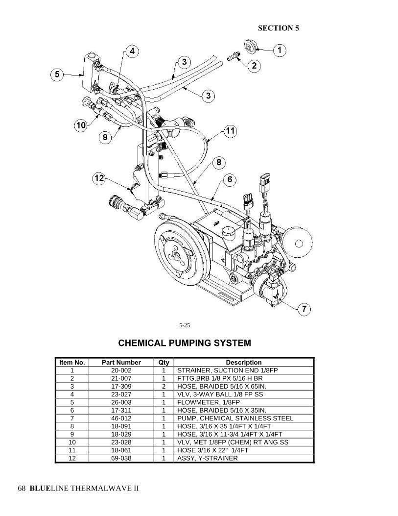
SECTION 5
BLUELINE THERMALWAVE II 68
5-25
CHEMICAL PUMPING SYSTEM
Item No. Part Number Qty Description
1 20-002 1 STRAINER, SUCTION END 1/8FP 2 21-007 1 FTTG,BRB 1/8 PX 5/16 H BR 3 17-309 2 HOSE, BRAIDED 5/16 X 65IN. 4 23-027 1 VLV, 3-WAY BALL 1/8 FP SS 5 26-003 1 FLOWMETER, 1/8FP 6 17-311 1 HOSE, BRAIDED 5/16 X 35IN. 7 46-012 1 PUMP, CHEMICAL STAINLESS STEEL 8 18-091 1 HOSE, 3/16 X 35 1/4FT X 1/4FT 9 18-029 1 HOSE, 3/16 X 11-3/4 1/4FT X 1/4FT 10 23-028 1 VLV, MET 1/8FP (CHEM) RT ANG SS 11 18-061 1 HOSE 3/16 X 22" 1/4FT 12 69-038 1 ASSY, Y-STRAINER
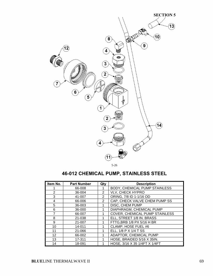
SECTION 5
BLUELINE THERMALWAVE II 69
5-26
46-012 CHEMICAL PUMP, STAINLESS STEEL
Item No. Part Number Qty Description 1 66-008 1 BODY, CHEMICAL PUMP STAINLESS 2 36-004 2 VLV, CHECK HYPRO 3 41-007 2 ORING, 7/8 ID 1-1/16 OD 4 66-006 2 CAP, CHECK VALVE CHEM PUMP SS 5 36-003 1 DISC, CHEM PUMP 6 36-000 1 DIAPHRAGM, CHEMICAL PUMP 7 66-007 1 COVER, CHEMICAL PUMP STAINLESS 8 21-038 1 ELL, STREET 1/8 IN. BRASS 9 21-007 1 FTTG,BRB 1/8 PX 5/16 H BR 10 14-011 1 CLAMP, HOSE FUEL #6 11 21-066 1 ELL, 1/8 P X 1/4 T SS 12 66-002 1 ADAPTOR, CHEMICAL PUMP 13 17-311 1 HOSE, BRAIDED 5/16 X 35IN. 14 18-091 1 HOSE, 3/16 X 35 1/4FT X 1/4FT
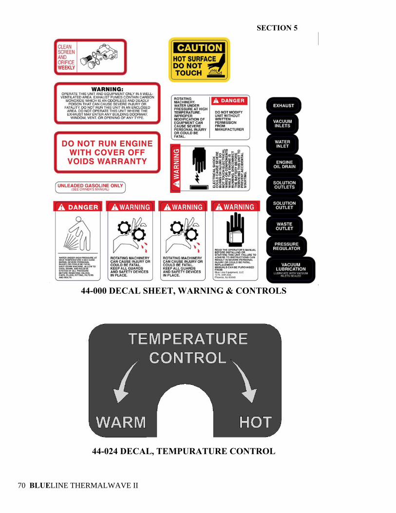
SECTION 5
BLUELINE THERMALWAVE II 70
44-000 DECAL SHEET, WARNING & CONTROLS
44-024 DECAL, TEMPURATURE CONTROL
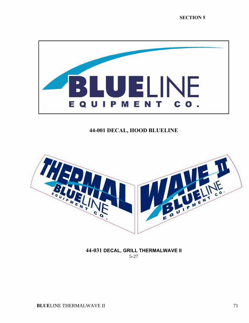
SECTION 5
BLUELINE THERMALWAVE II 71
44-001 DECAL, HOOD BLUELINE
44-031 DECAL, GRILL THERMALWAVE II 5-27
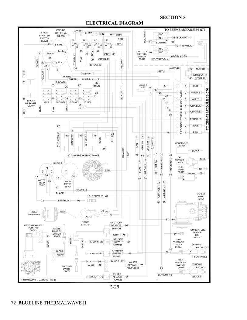
SECTION 5
BLUELINE THERMALWAVE II 72
ELECTRICAL DIAGRAM
HOURMETER26-007
-+
WATERTEMP26-010
GS J
12
12 BRN/YLW 65
1414
BLACK
16
17
15
BLK/WHT
RED/WHT15 67
WHITE
WHITE
BROWN
(PUMP)(T-PUMP)(W-PUMP)(AUX)
7
634
BLUE35
8G
RN
BR
N
YLW
302928
272625
256 3
187
425
6 3
187
425
6 3
187
425
6 3
187
4
GRN/BLK
33
YLW
YLW
/BLK
30GRN
GRN3
29
BRN
BRN/YLW
BRN2
28
YLW1
8630
85
87
87a86
3085
87
87a86
3085
87
87a86
3085
87
87a
CONDENSER30-024
ORANGE
BLACK
79
-+
RED/WHT
LED LIGHT30-022
BLK
OIL SENSOR29-013
PINK
91
8990
BLA
CK
WHITE
BLACK
WASTE PUMP ONSWITCH69-002
BLACK
WHITE
57
72
7778
7978
76
75
74
73
71
70
70
69
68
68
67
66
66
64
64
61
60
60
59
59
58
58
80
57
55
55
4445
43
42
41
4039
3837
34
BLU
E33
32
32
31
31
77
31
2726
25
24
24
23
23
22
22
21
21
20
20
19
19
18
1817
9
9
8
7
6
5
4
3
2
1
8
7
6
5
5
4
4
3
2
1
YLW/BLK
RED/BLKWHT/BLK
GR
N/B
LK
BRN
/YLW
YLW
/BLK
N/O
N/C
BLK
/WH
T
BLK/WHT
WHT/BLK
8 PO
SITI
ON
TER
MIN
AL
BLO
CK
30-
019
ENGINE RELAY (4)
34-010
-+
NISSANSTARTER
BLU
E
BLU
E
YELL
OW
BLK/WHT
-+
BLA
CK
WH
ITE
FUSED
POWER
WASTE
PUMP-OUT
UNFUSED
POWER
SHUT-OFFSWITCH69-000
BLK/WHT
BLUE N/CRED N/O (81)
BLACK C (82)
GR
EEN
BR
OW
N
ORANGESHUT-OFF
SWITCH
GRAY
BROWN
BLK/WHT
TRANSFER
PUMPGREEN
YELLOW
RED/WHT
TO ZEEMS MODULE 36-076
TO Z
EEM
S M
OD
ULE
36-
076
OPTIONAL WASTEPUMP KIT
68-003
LOW PRESSURE
SWITCH29-004
HIGH PRESSURE
SWITCH29-005
FUEL PUMP36-125
CAT 340 PUMP46-017
TEMPERATURESENSOR
285°34-008
THROTTLE CONTROLSWITCH29-011
3 POS. STARTERSWITCH29-007
30 AMP BREAKER
30-007
20 AMP BREAKER (4) 30-008
RED
BLUE
RED/WHT
GRN/BLK
WHITE
PURPLE
RED
BLK/WHT
BLK/WHT
BLK/WHT
OR
AN
GE
GREEN
BLK/WHT
BLU
E/BL
K
WH
T/G
RN
TAN
RED N/O
BLACK C
BLUE N/C
WH
T/G
RN
PU
RPL
EW
HIT
E
BLU
E
BLUE/BLK
WHT/RED/BLK
YLW/BLK
Auxiliary
Ignition
Battery
Starter
N/C
N/O
YELL
OW
GR
N/B
LK
RED
RED
WHT/GRNRED
RED
RED
30 A
MP
ThermalWave II 01/05/06 Rev. D
WHT/GRNRED
17
17
RE
D/W
HT
REDALERNATOR
NISSAN
RED
RE
D/W
HT
5-28
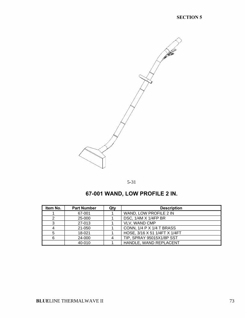
SECTION 5
BLUELINE THERMALWAVE II 73
5-31
67-001 WAND, LOW PROFILE 2 IN.
Item No. Part Number Qty Description
1 67-001 1 WAND, LOW PROFILE 2 IN 2 25-000 1 DSC, 1/4M X 1/4FP BR 3 27-013 1 VLV, WAND CMP 4 21-050 1 CONN, 1/4 P X 1/4 T BRASS 5 18-021 1 HOSE, 3/16 X 51 1/4FT X 1/4FT 6 24-000 4 TIP, SPRAY 95015X1/8P SST 40-010 1 HANDLE, WAND REPLACENT
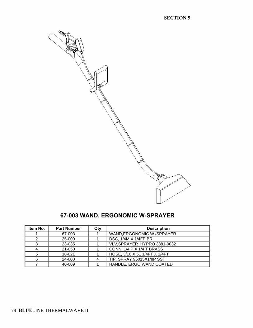
SECTION 5
BLUELINE THERMALWAVE II 74
67-003 WAND, ERGONOMIC W-SPRAYER
Item No. Part Number Qty Description 1 67-003 1 WAND,ERGONOMIC W /SPRAYER 2 25-000 1 DSC, 1/4M X 1/4FP BR 3 23-035 1 VLV,SPRAYER HYPRO 3381-0032 4 21-050 1 CONN, 1/4 P X 1/4 T BRASS 5 18-021 1 HOSE, 3/16 X 51 1/4FT X 1/4FT 6 24-000 4 TIP, SPRAY 95015X1/8P SST 7 40-009 1 HANDLE, ERGO WAND COATED
SECTION 5
BLUELINE THERMALWAVE II 75
5-30
68-020 ASSY, PRE-FILTER BOX WASTE TANK V2
Item No. Part Number Qty Description 1 61-012V2 1 ASSY, PRE-FILTER BOX V2 2 40-003 2 LATCH, PRE-FILTER BOX 3 61-039 1 ASSY, STRAINER BSKT PRE-FLTR BOX V2 4 61-020V2 1 ASSY, LID PRE-FILTER BOX V2 5 18-003 1 HOSE, VAC 2 IN. FLEX SUPER TM 6 19-009 1 CAP, WASTE TANK INLET 7 14-010 2 CLAMP, HOSE #32 8 17-421 1 HOSE, INT. VACUUM 2 IN X 6 FT 9 21-094 1 FTTG, 1-1/2 P X 2 H DRAIN 10 23-022 1 VLV, BALL 1-1/2 FP PVC DUMP
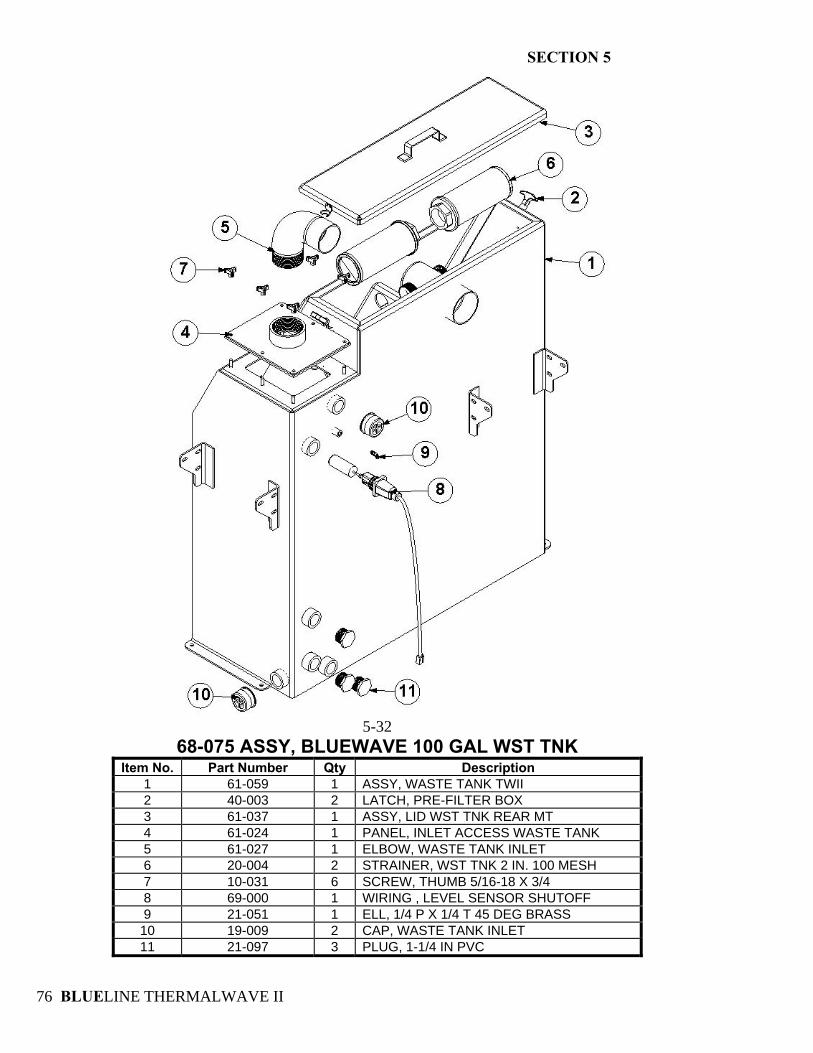
SECTION 5
BLUELINE THERMALWAVE II 76
5-32
68-075 ASSY, BLUEWAVE 100 GAL WST TNK Item No. Part Number Qty Description
1 61-059 1 ASSY, WASTE TANK TWII 2 40-003 2 LATCH, PRE-FILTER BOX 3 61-037 1 ASSY, LID WST TNK REAR MT 4 61-024 1 PANEL, INLET ACCESS WASTE TANK 5 61-027 1 ELBOW, WASTE TANK INLET 6 20-004 2 STRAINER, WST TNK 2 IN. 100 MESH 7 10-031 6 SCREW, THUMB 5/16-18 X 3/4 8 69-000 1 WIRING , LEVEL SENSOR SHUTOFF 9 21-051 1 ELL, 1/4 P X 1/4 T 45 DEG BRASS 10 19-009 2 CAP, WASTE TANK INLET 11 21-097 3 PLUG, 1-1/4 IN PVC
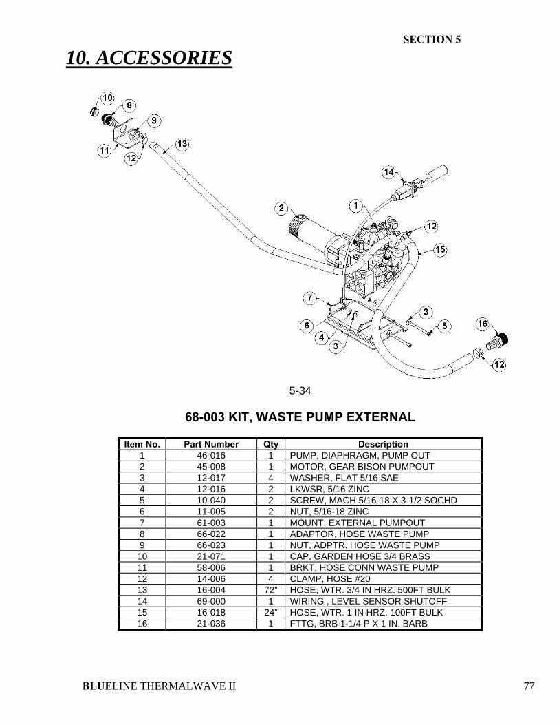
SECTION 5
BLUELINE THERMALWAVE II 77
10. ACCESSORIES
5-34
68-003 KIT, WASTE PUMP EXTERNAL
Item No. Part Number Qty Description
1 46-016 1 PUMP, DIAPHRAGM, PUMP OUT 2 45-008 1 MOTOR, GEAR BISON PUMPOUT 3 12-017 4 WASHER, FLAT 5/16 SAE 4 12-016 2 LKWSR, 5/16 ZINC 5 10-040 2 SCREW, MACH 5/16-18 X 3-1/2 SOCHD 6 11-005 2 NUT, 5/16-18 ZINC 7 61-003 1 MOUNT, EXTERNAL PUMPOUT 8 66-022 1 ADAPTOR, HOSE WASTE PUMP 9 66-023 1 NUT, ADPTR. HOSE WASTE PUMP 10 21-071 1 CAP, GARDEN HOSE 3/4 BRASS 11 58-006 1 BRKT, HOSE CONN WASTE PUMP 12 14-006 4 CLAMP, HOSE #20 13 16-004 72” HOSE, WTR. 3/4 IN HRZ. 500FT BULK 14 69-000 1 WIRING , LEVEL SENSOR SHUTOFF 15 16-018 24” HOSE, WTR. 1 IN HRZ. 100FT BULK 16 21-036 1 FTTG, BRB 1-1/4 P X 1 IN. BARB
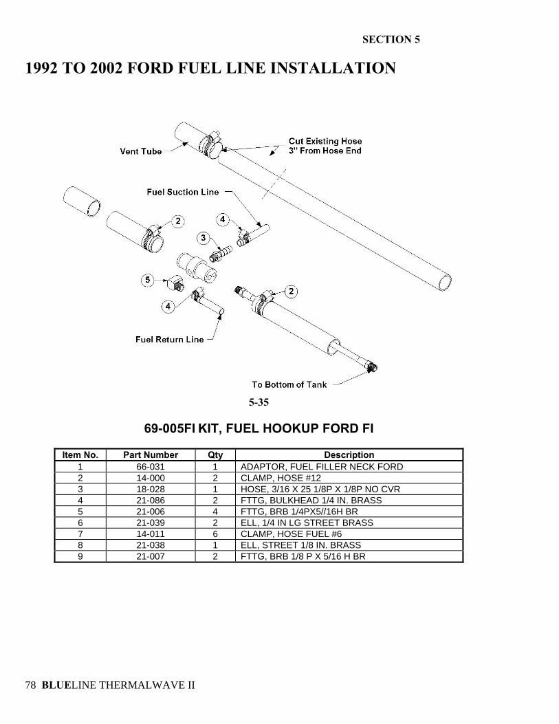
SECTION 5
BLUELINE THERMALWAVE II 78
1992 TO 2002 FORD FUEL LINE INSTALLATION
5-35
69-005FI KIT, FUEL HOOKUP FORD FI
Item No. Part Number Qty Description
1 66-031 1 ADAPTOR, FUEL FILLER NECK FORD 2 14-000 2 CLAMP, HOSE #12 3 18-028 1 HOSE, 3/16 X 25 1/8P X 1/8P NO CVR 4 21-086 2 FTTG, BULKHEAD 1/4 IN. BRASS 5 21-006 4 FTTG, BRB 1/4PX5//16H BR 6 21-039 2 ELL, 1/4 IN LG STREET BRASS 7 14-011 6 CLAMP, HOSE FUEL #6 8 21-038 1 ELL, STREET 1/8 IN. BRASS 9 21-007 2 FTTG, BRB 1/8 P X 5/16 H BR
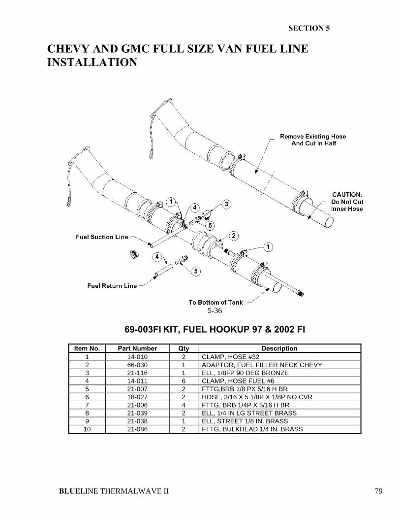
SECTION 5
BLUELINE THERMALWAVE II 79
CHEVY AND GMC FULL SIZE VAN FUEL LINE INSTALLATION
5-36
69-003FI KIT, FUEL HOOKUP 97 & 2002 FI
Item No. Part Number Qty Description
1 14-010 2 CLAMP, HOSE #32 2 66-030 1 ADAPTOR, FUEL FILLER NECK CHEVY 3 21-116 1 ELL, 1/8FP 90 DEG BRONZE 4 14-011 6 CLAMP, HOSE FUEL #6 5 21-007 2 FTTG,BRB 1/8 PX 5/16 H BR 6 18-027 2 HOSE, 3/16 X 5 1/8P X 1/8P NO CVR 7 21-006 4 FTTG, BRB 1/4P X 5/16 H BR 8 21-039 2 ELL, 1/4 IN LG STREET BRASS 9 21-038 1 ELL, STREET 1/8 IN. BRASS
10 21-086 2 FTTG, BULKHEAD 1/4 IN. BRASS
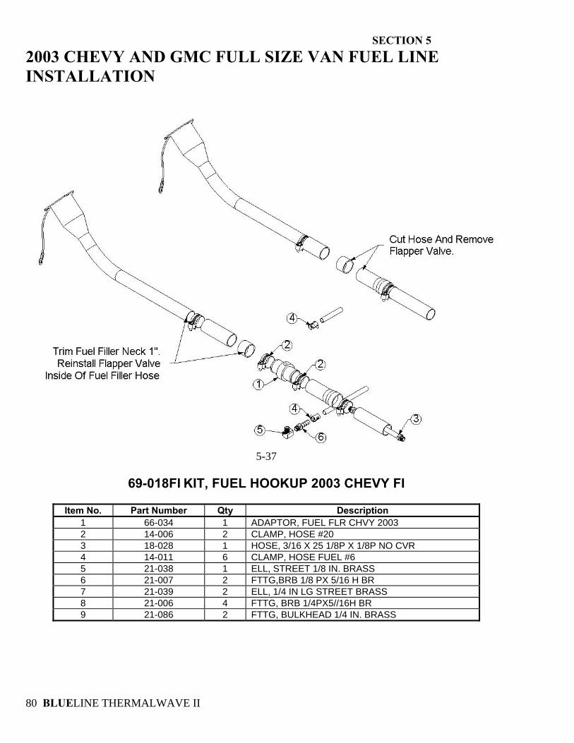
SECTION 5
BLUELINE THERMALWAVE II 80
2003 CHEVY AND GMC FULL SIZE VAN FUEL LINE INSTALLATION
5-37
69-018FI KIT, FUEL HOOKUP 2003 CHEVY FI
Item No. Part Number Qty Description
1 66-034 1 ADAPTOR, FUEL FLR CHVY 2003 2 14-006 2 CLAMP, HOSE #20 3 18-028 1 HOSE, 3/16 X 25 1/8P X 1/8P NO CVR 4 14-011 6 CLAMP, HOSE FUEL #6 5 21-038 1 ELL, STREET 1/8 IN. BRASS 6 21-007 2 FTTG,BRB 1/8 PX 5/16 H BR 7 21-039 2 ELL, 1/4 IN LG STREET BRASS 8 21-006 4 FTTG, BRB 1/4PX5//16H BR 9 21-086 2 FTTG, BULKHEAD 1/4 IN. BRASS
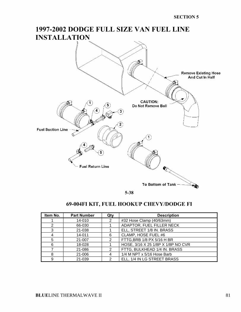
SECTION 5
BLUELINE THERMALWAVE II 81
1997-2002 DODGE FULL SIZE VAN FUEL LINE INSTALLATION
5-38
69-004FI KIT, FUEL HOOKUP CHEVY/DODGE FI
Item No. Part Number Qty Description
1 14-010 2 #32 Hose Clamp (40/63mm) 2 66-030 1 ADAPTOR, FUEL FILLER NECK 3 21-038 1 ELL, STREET 1/8 IN. BRASS 4 14-011 6 CLAMP, HOSE FUEL #6 5 21-007 2 FTTG,BRB 1/8 PX 5/16 H BR 6 18-028 1 HOSE, 3/16 X 25 1/8P X 1/8P NO CVR 7 21-086 2 FTTG, BULKHEAD 1/4 IN. BRASS 8 21-006 4 1/4 M NPT x 5/16 Hose Barb 9 21-039 2 ELL, 1/4 IN LG STREET BRASS
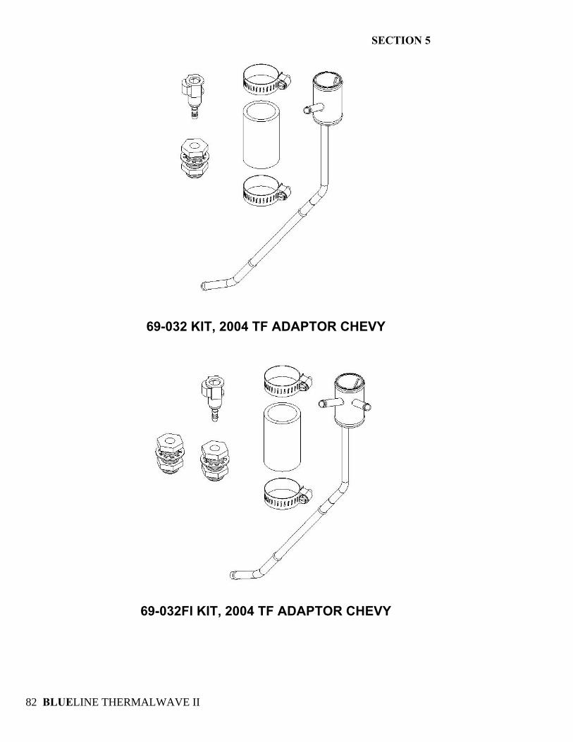
SECTION 5
BLUELINE THERMALWAVE II 82
69-032 KIT, 2004 TF ADAPTOR CHEVY
69-032FI KIT, 2004 TF ADAPTOR CHEVY
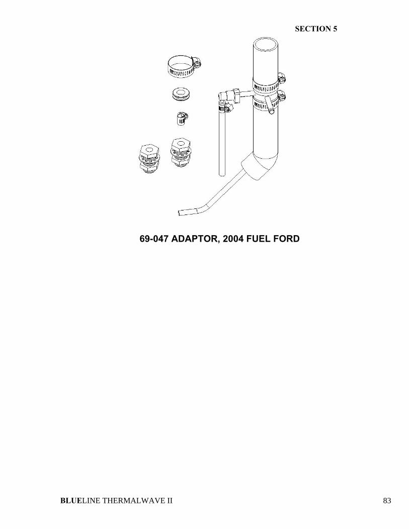
SECTION 5
BLUELINE THERMALWAVE II 83
69-047 ADAPTOR, 2004 FUEL FORD
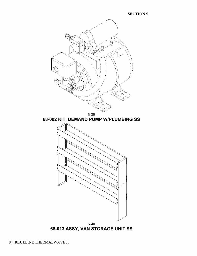
SECTION 5
BLUELINE THERMALWAVE II 84
5-39
68-002 KIT, DEMAND PUMP W/PLUMBING SS
5-40
68-013 ASSY, VAN STORAGE UNIT SS
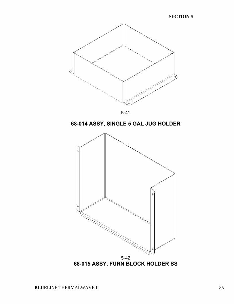
SECTION 5
BLUELINE THERMALWAVE II 85
5-41
68-014 ASSY, SINGLE 5 GAL JUG HOLDER
5-42
68-015 ASSY, FURN BLOCK HOLDER SS
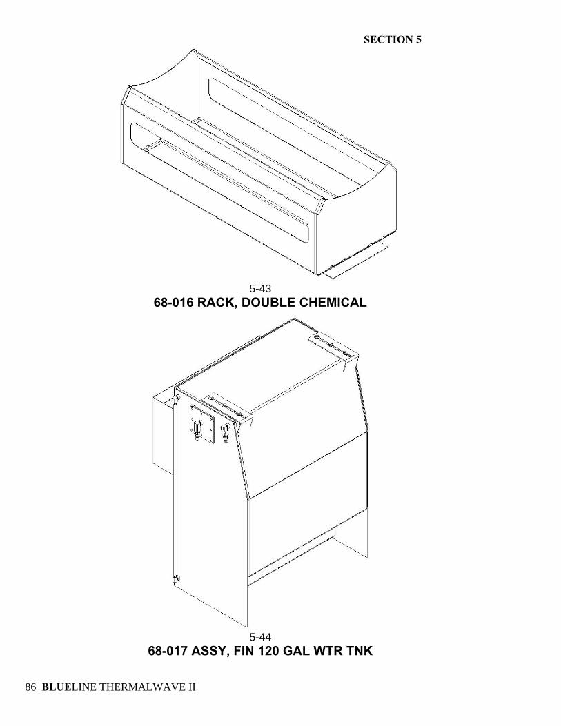
SECTION 5
BLUELINE THERMALWAVE II 86
5-43
68-016 RACK, DOUBLE CHEMICAL
5-44
68-017 ASSY, FIN 120 GAL WTR TNK
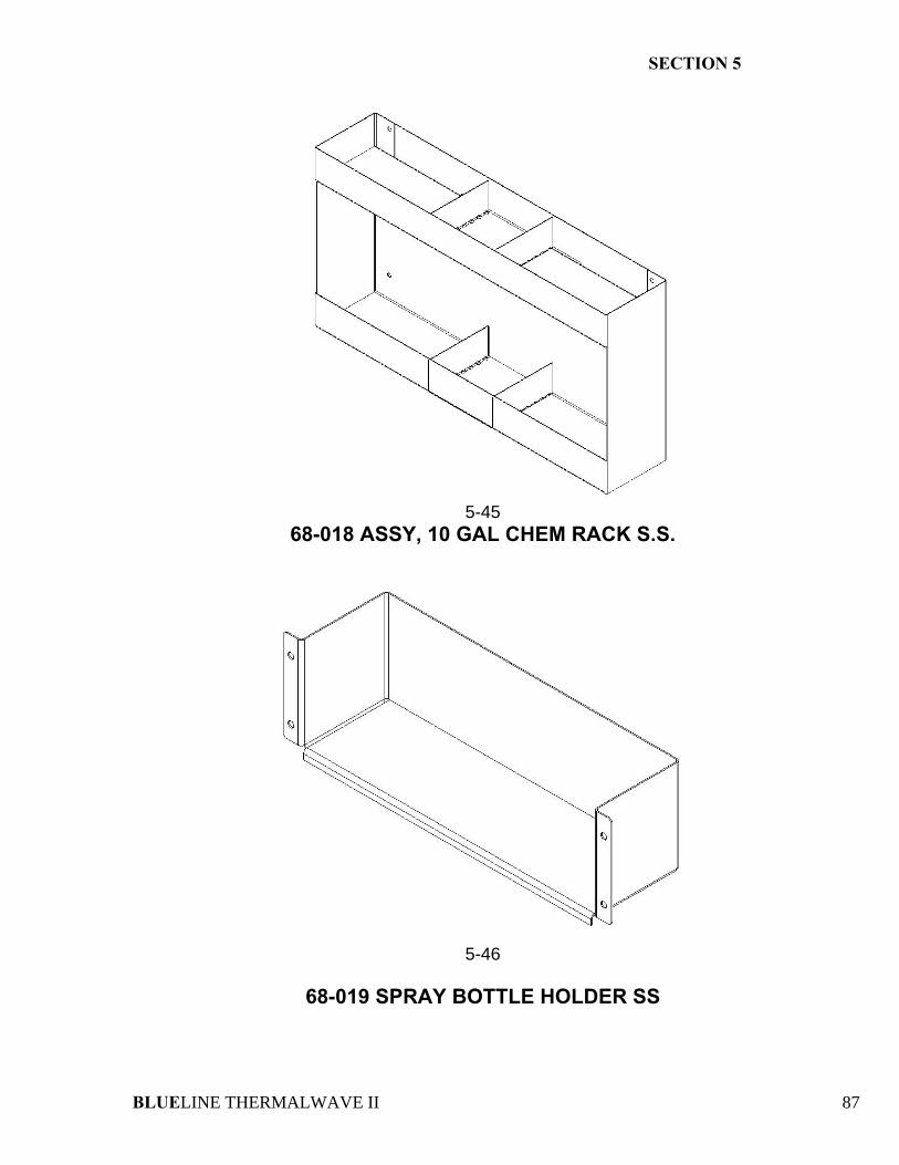
SECTION 5
BLUELINE THERMALWAVE II 87
5-45
68-018 ASSY, 10 GAL CHEM RACK S.S.
5-46
68-019 SPRAY BOTTLE HOLDER SS
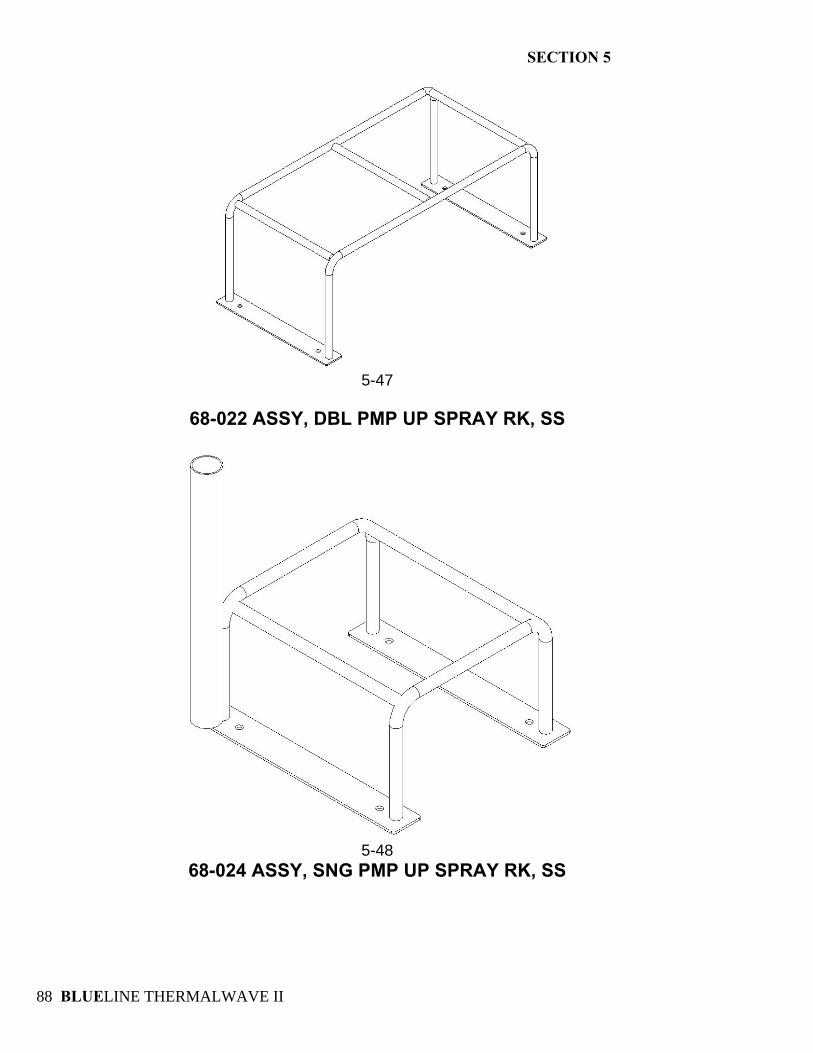
SECTION 5
BLUELINE THERMALWAVE II 88
5-47
68-022 ASSY, DBL PMP UP SPRAY RK, SS
5-48
68-024 ASSY, SNG PMP UP SPRAY RK, SS
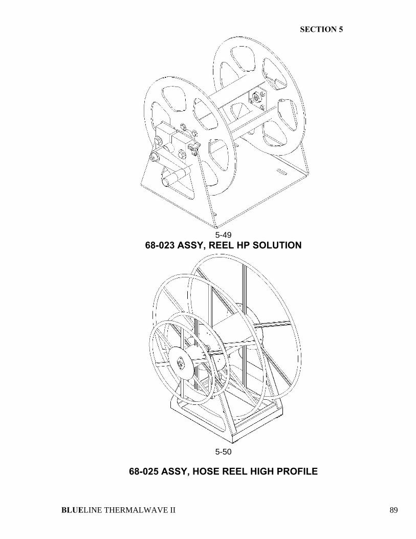
SECTION 5
BLUELINE THERMALWAVE II 89
5-49
68-023 ASSY, REEL HP SOLUTION
5-50
68-025 ASSY, HOSE REEL HIGH PROFILE
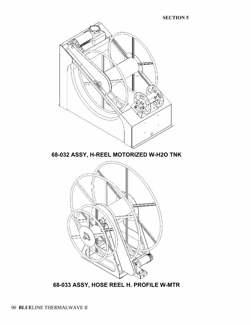
SECTION 5
BLUELINE THERMALWAVE II 90
68-032 ASSY, H-REEL MOTORIZED W-H2O TNK
68-033 ASSY, HOSE REEL H. PROFILE W-MTR
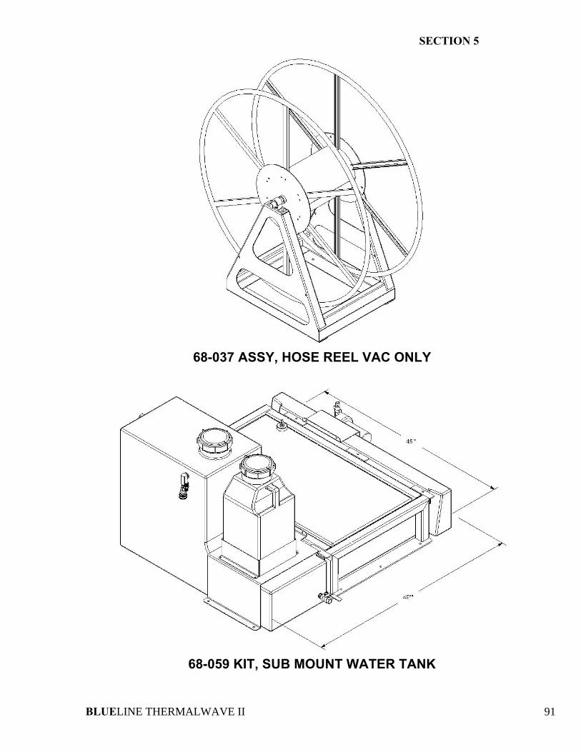
SECTION 5
BLUELINE THERMALWAVE II 91
68-037 ASSY, HOSE REEL VAC ONLY
68-059 KIT, SUB MOUNT WATER TANK
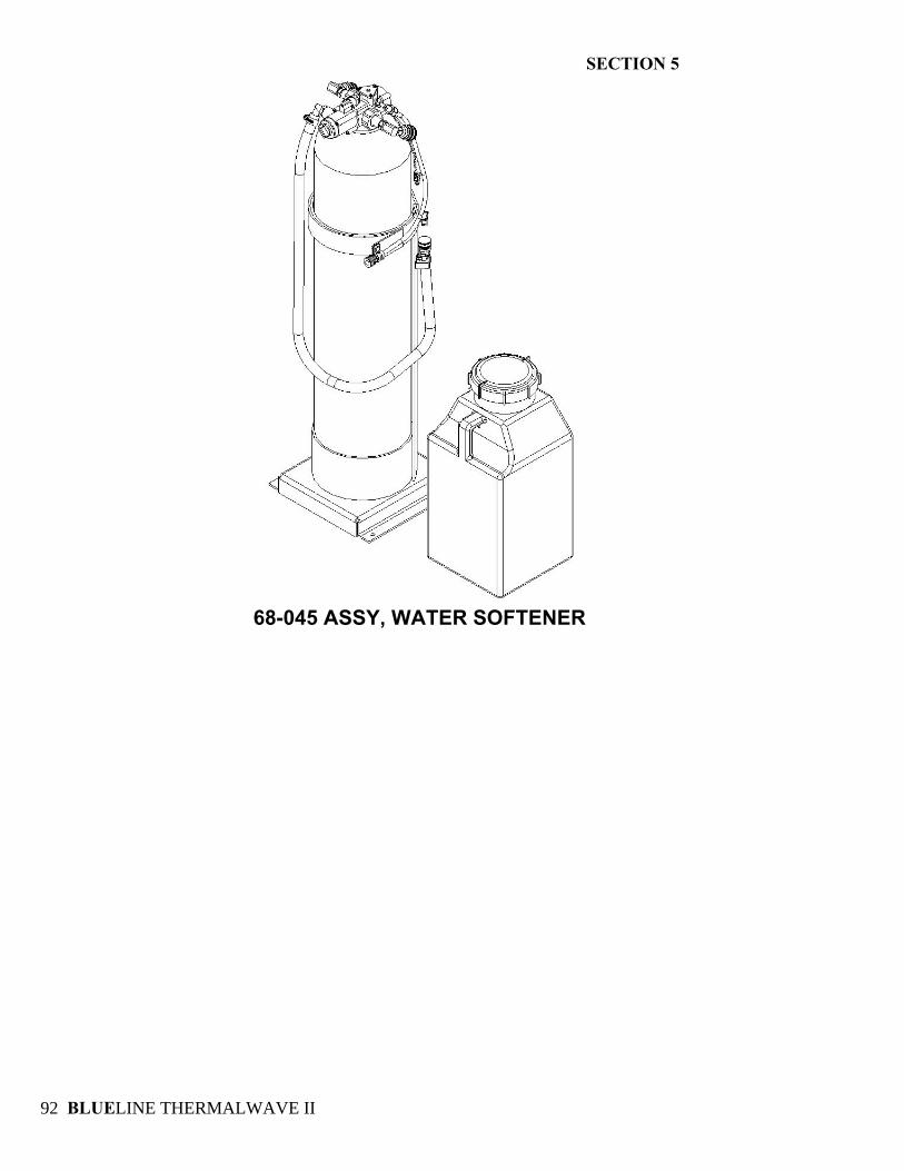
SECTION 5
BLUELINE THERMALWAVE II 92
68-045 ASSY, WATER SOFTENER