Nera Interlink Technical Description
58
4 - 11 GHz InterLink
Transcript of Nera Interlink Technical Description

7/22/2019 Nera Interlink Technical Description
http://slidepdf.com/reader/full/nera-interlink-technical-description 1/58
4 - 11 GHz
InterLink

7/22/2019 Nera Interlink Technical Description
http://slidepdf.com/reader/full/nera-interlink-technical-description 2/58

7/22/2019 Nera Interlink Technical Description
http://slidepdf.com/reader/full/nera-interlink-technical-description 3/58
The information in this documentation is subject to change without notice and describes only the product defined in
the introduction of this documentation. This documentation is intended for the use of Nera's customers only for the
purposes of the agreement under which the documentation is submitted, and no part of it may be reproduced or
transmitted in any form or means without the prior written permission of Nera.
The information or statements given in this documentation concerning the suitability, capacity, or performance of thementioned hardware or software products cannot be considered binding but shall be defined in the agreement made
between Nera and the customer. However, Nera has made all reasonable efforts to ensure that the instructions
contained in the documentation are adequate and free of material errors and omissions. Nera will, if necessary,
explain issues that may not be covered by the documentation. Nera's liability for any errors in the documentation is
limited to the documentary correction of errors.
NERA WILL NOT BE RESPONSIBLE IN ANY EVENT FOR ERRORS IN THIS DOCUMENTATION OR FOR ANY
DAMAGES, INCIDENTAL OR CONSEQUENTIAL (INCLUDING MONETARY LOSSES), that might arise from the
use of this documentation or the information in it. This documentation and the product it describes are considered
protected by copyright according to the applicable laws.
NERA logo is a registered trademark of Nera ASA. Other product names mentioned in this documentation may be
trademarks of their respective companies, and they are mentioned for identification purposes only.
Hereby, Nera Networks AS, declares that Nera InterLink Microwave Radio Family is in compliance with the essential
requirements and other relevant provisions of Directive: 1999/5/EC.
The product is marked with the CE marking and Notified Body number according to the Directive 1999/5/EC.
Copyright © Nera 2002. All rights reserved.

7/22/2019 Nera Interlink Technical Description
http://slidepdf.com/reader/full/nera-interlink-technical-description 4/58
INTERLINK Doc.no: NL2000\00206 Rev. B, 2003.01.31
2
Document history
Revision Date Summary of changes
Rev A 14.09.2001 First Issue
Rev B 31.01.2003 ANSI Frequency plans and references included3x34/45 Mb/s Multiplexer included

7/22/2019 Nera Interlink Technical Description
http://slidepdf.com/reader/full/nera-interlink-technical-description 5/58
INTERLINKDoc.no: NL2000\00206 Rev. B, 2003.01.31
3
ContentsPage
1. INTRODUCTION ................................................................ ........................................................... ................... 7
1.1 R EFERENCES .................................................................................................................................................7 1.2 TERMINOLOGY..............................................................................................................................................8
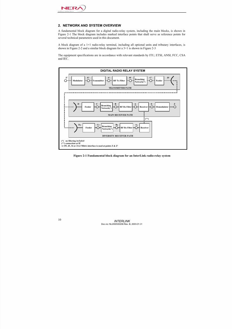
2. NETWORK AND SYSTEM OVERVIEW ............................................................. ....................................... 10
3. EQUIPMENT MAIN CHARACTERISTICS................................................................................................15
3.1 ITU-R/CEPT FREQUENCY BANDS AND CHANNEL ARRANGEMENTS............................................................15 3.2 EQUIPMENT SPECIFICATIONS ETSI........................................................... .................................................. 16 3.3 ANSI - TECHNICAL R EQUIREMENTS .........................................................................................................16 3.4 SYSTEM CONFIGURATIONS..........................................................................................................................17
3.4.1 Hot Standby ...................................................... ........................................................... .......................... 17 3.4.2 Terminal configurations ............................................................. ........................................................... 17 3.4.3 Modes of operation................ ................................................................ ................................................ 17 3.4.4 Radio channel identification..................... ...................................................................... ....................... 17
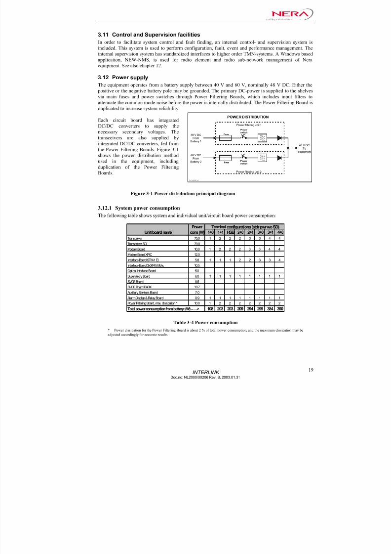
3.5 SYSTEM LOOP BACK POSSIBILITIES..............................................................................................................18 3.6 SAFETY CONDITIONS...................................................................................................................................18 3.7 E NVIRONMENTAL CONDITIONS ...................................................................................................................18 3.8 ELECTROMAGNETIC COMPATIBILITY CONDITIONS (EMC) ................................................................ .........18 3.9 EQUIPMENT TYPE APPROVAL ......................................................................................................................18 3.10 MECHANICAL CHARACTERISTICS ................................................................................................................18 3.11 CONTROL AND SUPERVISION FACILITIES.....................................................................................................19 3.12 POWER SUPPLY ...........................................................................................................................................19
3.12.1 System power consumption ........................................................... .................................................... 19 3.13 SYSTEM PERFORMANCE ..............................................................................................................................20
3.13.1 Equipment background BER (Residual BER) ................................................................... ................20 3.13.2 BER as a function of receiver input level................. ................................................................ .........20 3.13.3 System gain .......................................................................................................................................21
3.13.4 System signature / distortion sensitivity ................................................................ ............................ 21 3.13.5 System delay......................................................................................................................................22
3.14 I NTERFERENCE SENSITIVITY........................................................................................................................22 3.14.1 Co-channel interference sensitivity...................................................................................................22 3.14.2 Adjacent channel interference sensitivity.............................................................. ............................ 22 3.14.3 Threshold to Interference sensitivity (T/I).........................................................................................23
3.15 MEAN TIME BETWEEN FAILURE (MTBF)............................................................ ....................................... 23
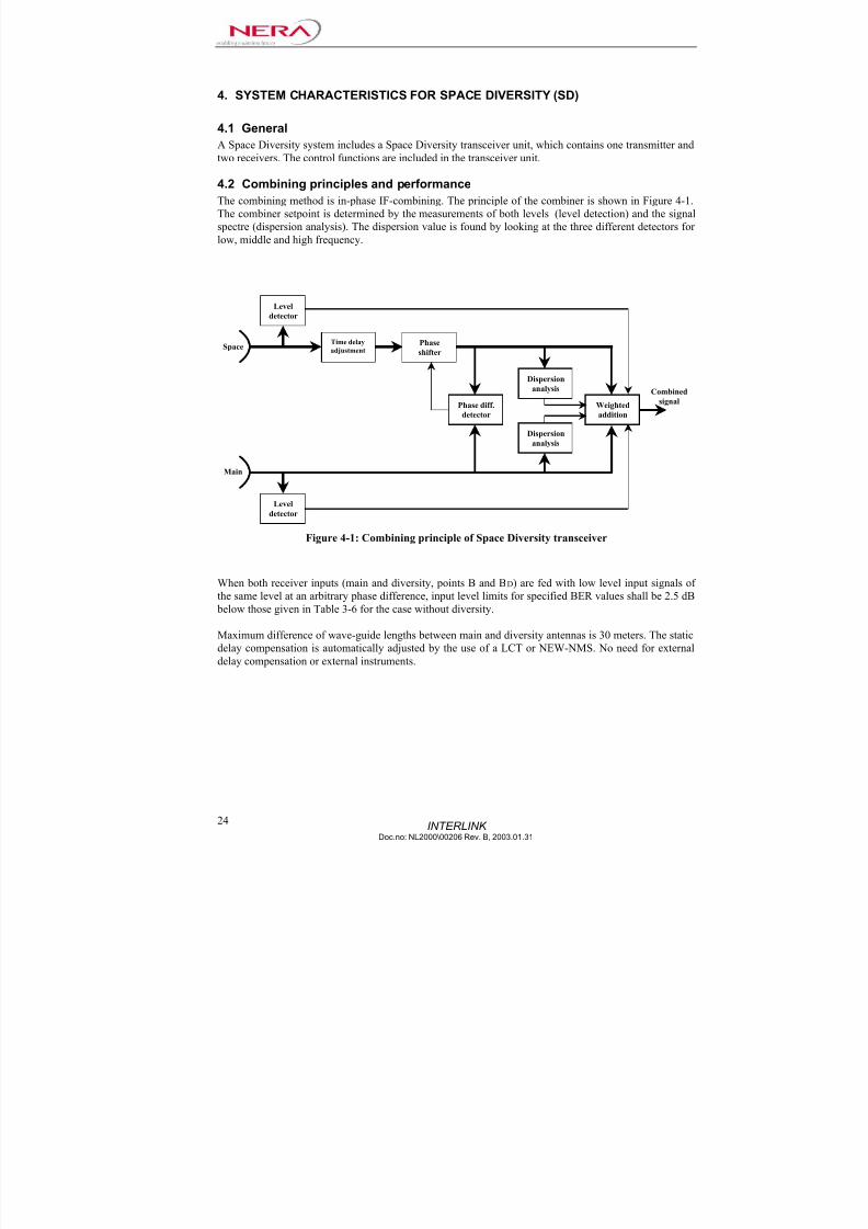
4. SYSTEM CHARACTERISTICS FOR SPACE DIVERSITY (SD).............................................................24
4.1 GENERAL ....................................................................................................................................................24 4.2 COMBINING PRINCIPLES AND PERFORMANCE ..............................................................................................24
5. WAVEGUIDE AND BRANCHING........................................................ ....................................................... 25
5.1 WAVE GUIDE FLANGES ...............................................................................................................................25 5.2 BRANCHING LOSS .......................................................................................................................................25 5.3 BRANCHING AND RF-FILTERING CHARACTERISTICS ...................................................................................25 5.4 RF-INPUT RETURN LOSS ..............................................................................................................................26
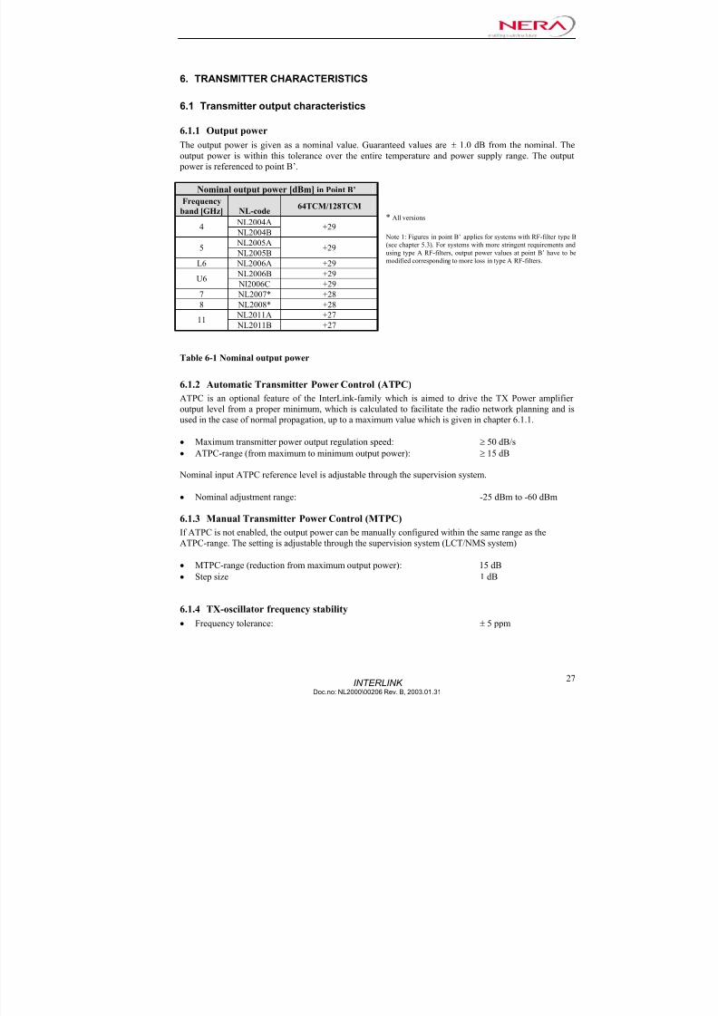
6. TRANSMITTER CHARACTERISTICS.......................................................................................................27
6.1 TRANSMITTER OUTPUT CHARACTERISTICS..................................................................................................27 6.1.1 Output power.........................................................................................................................................27 6.1.2 Automatic Transmitter Power Control (ATPC)....................................................................... .............. 27 6.1.3 Manual Transmitter Power Control (MTPC)...................................... .................................................. 27 6.1.4 TX-oscillator frequency stability .................................................................. ......................................... 27 6.1.5 Spurious emissions ............................................................. ........................................................... ........28
6.2 TRANSCEIVER MONITORING FACILITIES ......................................................................................................28 6.3 TRANSCEIVER ALARMS ...............................................................................................................................28
7. RECEIVER CHARACTERISTICS .......................................................... ..................................................... 29
7/22/2019 Nera Interlink Technical Description
http://slidepdf.com/reader/full/nera-interlink-technical-description 6/58
INTERLINK Doc.no: NL2000\00206 Rev. B, 2003.01.31
4
7.1 R ECEIVER INPUT CHARACTERISTICS............................................................................................................29 7.1.1 Local Rx-oscillator tolerance and stability ............................................................ ............................... 29 7.1.2 Receiver image rejection .............................................................. ......................................................... 29 7.1.3 Spurious emissions ............................................................. ........................................................... ........29 7.1.4 Noise figures............ ........................................................... ............................................................ .......29
8. MODEM CHARACTERISTICS......................................................... ........................................................... 30
8.1 MODULATOR ..............................................................................................................................................30 8.2 DEMODULATOR ..........................................................................................................................................30
8.2.1 Adaptive Time Domain Equalizer (ATDE)....................................................................... ..................... 30
9. BASEBAND CHARACTERISTICS...............................................................................................................31
9.1 GENERAL ....................................................................................................................................................31 9.2 TRANSMISSION INTERFACES .......................................................................................................................31
9.2.1 Transmission interface characteristics - STM-1 electrical....................................................................31 9.2.2 Transmission interface characteristics - STM-1/OC-3 optical – Intermediate Reach .......................... 31 9.2.3 Transmission interface characteristics – STM-1/OC-3 optical – Short Reach ..................................... 31 9.2.4 Transmission interface characteristics – 3x34 Mb/s (3xE3)............................................................ .....32 9.2.5 Transmission interface characteristics – 3x45 Mb/s (3xDS3)...............................................................32
9.3 3XE3/DS3 I NTERFACE BOARD ...................................................................................................................32 9.4 SCRAMBLING/DESCRAMBLING FUNCTIONS .................................................................................................32 9.5 SECTION/TRANSPORT OVER HEAD (SOH/TOH) ................................................... ...................................... 33
9.5.1 Frameword and parity bytes ............................................................................................ ..................... 33 9.5.2 Media specific bytes ........................................................................................... ................................... 33 9.5.3 Other SOH/TOH-bytes ................................................................ .......................................................... 33 9.5.4 DS1/E1 wayside traffic .............................................................. ............................................................ 34 9.5.5 64 kb/s channels ....................................................................................................................................34
9.6 SPECIFICATIONS OF JITTER AND WANDER ....................................................................................................34 9.6.1 STM-1/OC-3 traffic interface ....................................................... ......................................................... 34 9.6.2 E3 (34 Mb/s) traffic interface....................................................... ......................................................... 34 9.6.3 DS3 (45 Mb/s) traffic interface.......................................................................... .................................... 34 9.6.4 E1 (2.048 Mb/s) wayside interface........................................................... ............................................. 34 9.6.5 DS1 (1.544 Mb/s) wayside interface............................................................................................... .......34
10. SERVICE AND WAYSIDE TRAFFIC......................................................................................................34
10.1 GENERAL ....................................................................................................................................................34 10.2 SERVICE TRAFFIC........................................................................................................................................35
10.2.1 Service telephones.............................................................................................................................35 10.2.2 PABX-connection:..................................................... ................................................................ ........36 10.2.3 64 kb/s service channels....................................................................................................................36
10.3 WAYSIDE TRAFFIC ......................................................................................................................................36 10.3.1 DS1 (1.544 Mb/s) wayside interface .................................................................. ............................... 36 10.3.2 E1 (2.048 Mb/s) wayside interface............................................................................. ....................... 36
11. RADIO PROTECTION SWITCHING (RPS)...........................................................................................37
11.1 GENERAL ....................................................................................................................................................37 11.2 BASE BAND SWITCHING OPERATIONS ..........................................................................................................37 11.3 SWITCHING CAPABILITY..............................................................................................................................37 11.4 PRIORITY OF PROTECTION SWITCHING ........................................................................................................37 11.5 SPECIFICATION OF THE PROTECTION SWITCHING SYSTEM ...........................................................................37
11.5.1 Alignment specification....... ................................................................ .............................................. 37 11.5.2 Switching criteria..............................................................................................................................37 11.5.3 Switching operation time...................................................................................................................38
12. SYSTEM SUPERVISORY CHARACTERISTICS......................................................... ......................... 38
12.1 GENERAL ....................................................................................................................................................38 12.2 EVENT LOGGING .........................................................................................................................................39
12.3 MONITORING OF SYSTEM PERFORMANCE ....................................................................................................39 12.3.1 Parity error monitoring...................................................................................... ............................... 39 12.3.2 System performance calculations......................................................................................................39

7/22/2019 Nera Interlink Technical Description
http://slidepdf.com/reader/full/nera-interlink-technical-description 7/58
7/22/2019 Nera Interlink Technical Description
http://slidepdf.com/reader/full/nera-interlink-technical-description 8/58
INTERLINK Doc.no: NL2000\00206 Rev. B, 2003.01.31
6
Table 6-1 Nominal output power ................................................................................................................27 Table 7-1 Noise figure ................................................................................................................................29 Table 9-1: Utilization of SOH/TOH-bytes;.................................................................................................33 Table 11-1 Switching operation time..........................................................................................................38 Table 12-1 System performance data..........................................................................................................39
Appendix Page
APPENDIX 1 CHANNEL FREQUENCIES ................................................................. ...................................... 46

7/22/2019 Nera Interlink Technical Description
http://slidepdf.com/reader/full/nera-interlink-technical-description 9/58
INTERLINKDoc.no: NL2000\00206 Rev. B, 2003.01.31
7
1. INTRODUCTION
InterLink is a scalable indoor mounted radio-relay equipment for transmission of N x 155 Mb/s in the
frequency bands 4 - 11 GHz with details as specified in chapter 3.1and 3.3.
Line interfaces for the equipment includes STM-1/OC-3, 3 x E3/DS-3, and E1/DS1 wayside.
1.1 References
Document code: Title/Description:
ETSI EN 301 489-4 V1.2.1 (2000-08) Electromagnetic compatibility and Radio spectrum Matters (ERM); ElectroMagnetic
Compatibility (EMC) standard for radio equipment and services; Part 4: Specific conditions for
fixed radio links and ancillary equipment and services. For grade B equipment
ETSI ETS 300 019-1-1 ed.1 (1992-02) Classification of environmental conditions; Storage. Class 1.2, weather protected
ETSI ETS 300 019-1-2 ed.1 (1992-02) Classification of environmental conditions; Transportation. Class 2.3, public transportation
ETSI ETS 300 019-1-3 ed.1 (1992-02) Classification of environmental conditions; Stationary use at weather protected locations. Class
3.2, partly temperature controlled locations
ETSI ETS 300 019-1-4 ed.1 (1992-02) Classification of environmental conditions; Stationary use at non-weather protected locations
ETSI EN 300 234 V1.2.1 (1998-10)ETSI EN 300 234 V1.3.1 (2001-02) High capacity DRRS carrying 1 x STM-1 signals and operating in frequency bands with about 30MHz channel spacing and alternated arrangements
ETSI EN 301 127 V1.1.1 (2000-09)
ETSI EN 301 127 V1.2.1 (2001-06)
High capacity digital radio systems carrying SDH signals (up to 2 x STM-1) in frequency bands
with about 30 MHz channel spacing and using Co-polar arrangements or Co-Channel Dual
Polarized (CCDP) operation
ETSI EN 301 461V1.1.1 (2000-09)
ETSI EN 301 461V1.2.1 (2001-02)
ETSI EN 301 461V1.3.1 (2002-07)
High capacity fixed radio systems carrying SDH signals (2 x STM-1) in frequency bands with 40
MHz channel spacing and using Co-channel Dual Polarized (CCPD) operation
CENELEC EN 60950: 2000 Safety of information technology equipment
CENELEC EN 60215: 1989 Safety requirements for radio transmitting equipment
CENELEC EN 60825-1 1994 Safety of laser products, Part 1: Equipment classification, requirements and user’s guide
CENELEC EN 60825-2 2000 Safety of laser products, Part 2: Safety of optical fiber communication systems
ITU-R Rec. F.382-7 (1997-09) Radio-frequency channel arrangements for radio-relay systems operating in the 2 and 4 GHz
bands
ITU-R Rec. F.635-6 (2001) Radio-frequency channel arr. based on a homogenous pattern for radio-relay systems operating in
the 4 GHz bandITU-R Rec. F.746-5 (2001) Radio-frequency channel arrangements for radio-relay systems
ITU-R Rec. F.1099-3 (1999-02) Radio-frequency channel arr. for high-capacity digital radio-relay systems in the 5 GHz (4400 -
5000 MHz) band
ITU-R Rec. F.383-7 (2001) Radio-frequency channel arrangements for high capacity radio-relay systems operating in the
lower 6 GHz band
ITU-R Rec. F.384-7 (1999-02) Radio-frequency channel arrangements for medium and high capacity analogue or digital radio-
relay systems operating in the upper 6 GHz band
ITU-R Rec. F.385-7 (2001) Radio-frequency channel arrangements for radio-relay systems operating in the 7 GHz band
ITU-R Rec. F.386-6 (1999-02) Radio-frequency channel arrangements for medium and high capacity analogue or digital radio-
relay systems operating in the 8 GHz band
ITU-R Rec. F.387-8 (1999-02) Radio-frequency channel arrangements for radio-relay systems operating in the 11 GHz band
ITU-R Rec. F.750-4 (2000-05) Architectures and functional aspects of radio-relay systems for synchronous digital hierarchy
(SDH)-based network
ITU-R Rec. F.1191-1 (1997-09) Bandwidths and unwanted emissions of digital radio-relay systems
ITU-R Rec. SM.329-8 (2000-04) Spurious emissionsITU-T Rec. G.703 (10/98) Physical/electrical characteristics of hierarchical digital interfaces
ITU-T Rec. G.707 (10/00) Network node interface for the synchronous digital hierarchy (SDH)
ITU-T Rec. G.711 (11/88) Pulse code modulation (PCM) of voice frequencies
ITU-T Rec. G.712 (11/96) Transmission performance characteristics of pulse code modulation channels
ITU-T Rec. G.783 (10/00) Characteristics of synchronous digital hierarchy (SDH) equipment functional blocks
ITU-T Rec. G.821 (08/96) Error performance of an international digital connection operating at a bit rate below the primary
rate and forming part of an integrated services digital network
ITU-T Rec. G.823 (03/00) The control of jitter and wander within digital networks which are based on the 2048 kbit/s
hierarchy
ITU-T Rec. G.824 (03/00) The control of jitter and wander within digital networks which are based on the 1544 kbit/s
hierarchy
ITU-T Rec. G.826 (02/99) Error performance parameters and objectives for international, constant bit rate digital paths at or
above the primary rate
ITU-T Rec. G.957 (06/99) Optical interfaces for equipments and systems relating to the synchronous digital hierarchy
ITU-T Rec. G.958 (11/94) Digital line systems based on the synchronous digital hierarchy for use on optical fiber cableITU-T Rec. Q.23 (11/88) Technical features of push-button telephone sets
ETSI TR 101 036-1 V1.2.1 (2000-01) Fixed Radio Systems; Point-to-point equipment; Generic wordings for standards on digital radio
systems characteristics; Part 1: General aspects and point-to-point equipment parameters

7/22/2019 Nera Interlink Technical Description
http://slidepdf.com/reader/full/nera-interlink-technical-description 10/58
INTERLINK Doc.no: NL2000\00206 Rev. B, 2003.01.31
8
CEPT/ERC Rec. 74-01, distrib. B Spurious Emissions
CEPT/ERC Rec. 12-08 E Harmonized radio frequency channel arrangements and block allocations for low, medium and
high capacity systems in the band 3600 to 4200 MHz
CEPT/ECC Rec 02-06 Preferred channel arrangement for digital fixed service systems operating in the frequency range
7125-8500 MHz
CEPT/ERC Rec 14-01 E Radio-frequency channel arrangements for high capacity analogue and digital radio-relay systems
operating in the band 5925 MHz – 6425 MHz
CEPT/ERC Rec 14-02 E Radio-frequency channel arrangements for medium and high capacity digital radio-relay systems
operating in the band 6425 MHz – 7125 MHz
CEPT/ERC Rec. 12-06 E Harmonized radio frequency channel arrangements for digital terrestrial fixed systems operating in
the band 10.7 – 11.7 GHz
ANSI/Industry Canada:
Radio Frequency Channel Plans:
FCC 47 CFR Part 101 Fixed Microwave Services
SRSP – 305.9 Technical Requirements for Line-of-sight Radio Systems Operating in the Fixed Service in the
Band 5915 – 6425 MHz
SRSP – 306.4 Technical Requirements for Line-of-sight Radio Systems Operating in the Fixed Service in the
Band – 6425 – 6930 MHz
SRSP – 307.1 Technical Requirements for Fixed Line-of-Sight Radio Systems Operating in the Band 7125-7725
MHz
SRSP – 307.7 Technical Requirements for Fixed Line-of-sight Radio Systems Operating in the Band 7725-8275MHz
SRSP – 310.7 Technical Requirements for Fixed Line-of-sight Radio Systems Operating in the Band 10.7-11.7
GHz
Electromagnetic Compatibility:
FCC 47CFR Part 15 Radio Frequency Devices (EMC regulations)
Safety:
CAN/CSA 22.2 No. 60950-00 Safety – Information processing and business equipment
SONET:
ANSI Rec. T1.105 SONET - Basic Description including Multiplex Structure, Rates and Formats
ANSI Rec. T1.105.06-1996 Telecommunications-Synchronous Optical Network (SONET): Physical Layer Specifications
ANSI Rec. T1.646-1995 Broadband ISDN Physical Layer Specification for User Network Interfaces Including DS1/ATM
ANSI T1.102-1993 Digital Hierarchy – Electrical Interfaces”.
1.2 TerminologyAbbreviations Descriptions
ACAP Adjacent Channel Alternate Polarization
ACCP Adjacent Channel Co-Polarization
ACF Alarm and Control Function
ADM Add/Drop Multiplexer
AIS Alarm Indication Signal
APS Automatic Protection Switching
ASIC Application Specific Integrated Circuit
ATDE Adaptive Time Domain Equalizer
ATPC Automatic Transmitter Power Control
AU Administrative Unit
AUG Administrative Unit Group
AUI Attachment Unit Interface
BER Bit Error Rate
BIP Bit Interleaved Parity
C Container
CCDP Co-Channel Dual Polarized
CRC Cyclic Redundancy Check
DCC Data Communications Channel
ECC Embedded Control Channel
EMC ElectroMagnetic Compatibility
EW Early Warning
FIR Finite Impulse Response
HBER High Bit Error Rate
LBER Low Bit Error Rate
LCT Local Craft Terminal
LOF Loss Of Frame
LOH Line OverHead (LOH is a SONET term with same meaning as MSOH in SDH networks)
LOS Loss Of Signal
MLM Multi-Longitudinal Mode
MMF Multi-Mode Fiber
MS Multiplex SectionMSOH Multiplex Section OverHead (MSOH is a SDH term with same meaning as LOH in SONET networks)
MST Multiplex Section Termination
MTBF Mean Time Between Failure

7/22/2019 Nera Interlink Technical Description
http://slidepdf.com/reader/full/nera-interlink-technical-description 11/58
INTERLINKDoc.no: NL2000\00206 Rev. B, 2003.01.31
9
NEW-NMS Nera Element vieW-Network Management System. A NERA proprietary radio-element and sub network management PC-program
NNI Network Node Interface
OOF Out Of Frame
OC-3 Optical Carrier – level 3 = 155Mbit/s (OC-1 – level 1 = 51.84 Mb/s)
PABX Private Automatic Branch eXchange
PCM Pulse Code Modulation
PDH Plesiochronous Digital Hierarchy
PLL Phase Locked Loop
POH Path OverHeadPRBS Pseudo Random Bit Sequence
PSK Phase Shift Keying
PUI Peripheral Unit Interface
RF Radio Frequency
RFID Radio Frequency Identification
RPS Radio Protection Switching
RRR Radio-Relay Regenerator
RRT Radio-Relay Terminal
RS Regenerator Section
RSL Receiver input Signal Level
RSOH Regenerator Section OverHead (RSOH is a SDH term with same meaning as SOH in SONET networks)
RST Regenerator Section Termination
SDH Synchronous Digital Hierarchy
SETS Synchronous Equipment Timing Source
SMF Single Mode Fiber
SNR Signal-to-noise ratio
SOH/TOH Section OverHead/Transport OverHead (SOH is used in SDH networks, TOH is used in SONET networks)
SONET Synchronous O ptical Network
SORP SDH/SONET Overhead & Radio Processor
SPE Synchronous Payload Envelope (An STS frame consist of Transport OverHead and the SPE)
STM-0 A subset of STM-1 (generally 51.84 Mb/s but may also be 55.296 Mb/s)
STM-1 Synchronous Transport Module -1 (1 represents the lowest defined data rate; 155.520 Mb/s)
STS-1Synchronous Transport Signal level 1 (Lowest level of the SONET hierarchy, higher levels are multiple of STS-1, OC-1 is the optically
equivalent counterpart for STS-1)
SU Supervisory Unit
SVCE SerVice ChannEl (used to define the voice channel circuit board)
TDM1 Tributary Data Mapper 1
TMN Telecommunication Management Network
TRIB1 Tributary Interface Block 1
TU Tributary Unit
TUG Tributary Unit Group
VC Virtual Container
XPI Cross Polar InterferenceXPIC Cross Polar Interference Canceller
7/22/2019 Nera Interlink Technical Description
http://slidepdf.com/reader/full/nera-interlink-technical-description 12/58

7/22/2019 Nera Interlink Technical Description
http://slidepdf.com/reader/full/nera-interlink-technical-description 13/58
I NT E RL I NK
D o c .n o: NL 2 0
0 0 \ 0 0 2 0 6 R ev .B ,2 0 0 3 . 0 1 . 3 1
1
1
Supervisory Board
1+1 TERMINAL
Interface Baseband Board
155.520 Mb/s
ServiceTelephone
4x64kb/sChannels
PABXAdapter function
SVCE Board
ACF
Auxiliary Services Board
ACF
ACF
LINEINTERFACE
MSOH Pros.
&Wayside
Splitter &
AlignmentSwitch
SORP-ASIC
ACF
SORP-ASICRSOH
Proces.
SORP-ASICRSOH
Proces.
64kb/s Channels
SVCE Telephoneext connections
External ControlsOutput
Output Alarms
SOH-ASICSOH
Adapter
Wayside
PABXConnections
AlarmAdapter function
Alarmout
function
ACF
Analoginput
function
Analog voltages
SUSVCE com.
InterLinkExternal Alarms
Input
F i g ur e 2 -2 Bl o c k d i a gr am f or a1 + 1 t e r mi n al

7/22/2019 Nera Interlink Technical Description
http://slidepdf.com/reader/full/nera-interlink-technical-description 14/58

7/22/2019 Nera Interlink Technical Description
http://slidepdf.com/reader/full/nera-interlink-technical-description 15/58
INTERLINKDoc.no: NL2000\00206 Rev. B, 2003.01.31
13
INTFC C
INPUT
OUTPUT
INTFC B
INPUT
OUTPUT
D
C
B
A
INTFC A
4
INTFC C
INPUT
OUTPUT
INTFC B
INPUT
OUTPUT
INTFC A
5
INTFC C
INPUT
OUTPUT
INTFC B
INPUT
OUTPUT
INTFCA
6
INTFC C
INPUT
OUTPUT
INTFC B
INPUT
OUTPUT
INTFCA
7
INTFC C
INPUT
OUTPUT
INTFC B
INPUT
OUTPUT
INTFC A
8
INTFC C
INPUT
OUTPUT
INTFC B
INPUT
OUTPUT
INTFCA
9
INTFC C
INPUT
OUTPUT
INTFC B
INPUT
OUTPUT
INTFC A
10
D
C
B
A
TRANSCEIVERPOWERCONNECTIONSTB2 TB3
IC1S1 J1 (EXT CON) J2 (SU TEST)
- GND + - GND + - GND + - GND +
ON
1 2
RMVRST
RMVRST
RMVRST
I N T E R F A C E B A S E B A N D
B D
M O D E M B D
M O D E M B D
S V C E B D
S U P E R V I S O R Y
B D
PWRON
OFF
PWRON
OFF
WARNING
POWER
TRANSCEIVER
WARNING
POWER
TRANSCEIVER
ALM
PWR
ALM ALM
PWR PWR
ALM ALM
PWR PWR
RMVRST
RMVRST
Figure 2-4 Subrack layout for a 1+1 terminal
7/22/2019 Nera Interlink Technical Description
http://slidepdf.com/reader/full/nera-interlink-technical-description 16/58
INTERLINK Doc.no: NL2000\00206 Rev. B, 2003.01.31
14
2 1
INTFC C
INPUT
OUTPUT
INTFC B
INPUT
OUTPUT
D
C
B
A
INTFCA
4
INTFC C
INPUT
OUTPUT
INTFC B
INPUT
OUTPUT
INTFCA
5
INTFC C
INPUT
OUTPUT
INTFC B
INPUT
OUTPUT
INTFCA
6
INTFC C
INPUT
OUTPUT
INTFC B
INPUT
OUTPUT
INTFC A
7
INTFC C
INPUT
OUTPUT
INTFC B
INPUT
OUTPUT
INTFC A
8
INTFC C
INPUT
OUTPUT
INTFC B
INPUT
OUTPUT
INTFC A
9 0
3
TRANSCEIVERPOWERCONNECTIONSTB2 TB3
IC1S1 J1(EXTCON) J2(SU TEST)
- GND + - GND + - GND + - GND +
ON
1 2
RMV
RST
RMV
RST
A U X I L I A R Y S E R V I C E S B
D
RMV
RST
S V C E B D
RMV
RST
S U P E R V I S O R Y B D
PWR
ON
OFF
PWR
ON
OFF
INTFC C
INPUT
OUTPUT
INTFC B
INPUT
OUTPUT
INTFC A
21
D
C
B
A
INTFC C
INPUT
OUTPUT
INTFC B
INPUT
OUTPUT
INTFC A
10
INTFC C
INPUT
OUTPUT
INTFC B
INPUT
OUTPUT
INTFCA
11
INTFC C
INPUT
OUTPUT
INTFC B
INPUT
OUTPUT
INTFCA
12
INTFC C
INPUT
OUTPUT
INTFC B
INPUT
OUTPUT
INTFCA
13
INTFC C
INPUT
OUTPUT
INTFC B
INPUT
OUTPUT
INTFCA
14
INTFC C
INPUT
OUTPUT
INTFC B
INPUT
OUTPUT
INTFCA
15
INTFC C
INPUT
OUTPUT
INTFC B
INPUT
OUTPUT
INTFC A
16
INTFC C
INPUT
OUTPUT
INTFC B
INPUT
OUTPUT
INTFCA
17
INTFC C
INPUT
OUTPUT
INTFC B
INPUT
OUTPUT
INTFCA
18
INTFC C
INPUT
OUTPUT
INTFC B
INPUT
OUTPUT
INTFCA
19
INTFC C
INPUT
OUTPUT
INTFC B
INPUT
OUTPUT
INTFC A
20
RMV
RST
RMVRST
RMVRST
I N T E R F A C E B A S E B A N D
B D
RMVRST
RMV
RST
M O D E M B D
RMVRST
I N T E R F A C E B A S E B A N D
B D
RMVRST
WARNING
POWER
TRANSCEIVER
WARNING
POWER
TRANSCEIVER
WARNING
POWER
TRANSCEIVER
WARNING
POWER
TRANSCEIVER
M O D E M B D
M O D E M B D
M O D E M B D
I N T E R F A C E B A S E B A N D
B D
S V C E B D
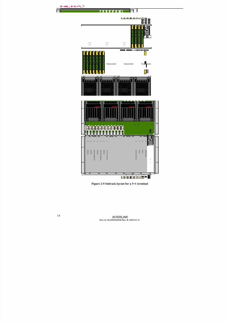
Figure 2-5 Subrack layout for a 3+1 terminal
7/22/2019 Nera Interlink Technical Description
http://slidepdf.com/reader/full/nera-interlink-technical-description 17/58
INTERLINKDoc.no: NL2000\00206 Rev. B, 2003.01.31
15
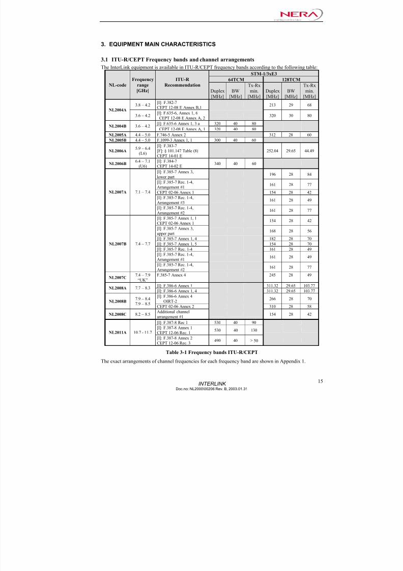
3. EQUIPMENT MAIN CHARACTERISTICS
3.1 ITU-R/CEPT Frequency bands and channel arrangements
The InterLink equipment is available in ITU-R/CEPT frequency bands according to the following table:
STM-1/3xE3
64TCM 128TCMNL-code
Frequency
range
[GHz]
ITU-R
Recommendation
Duplex
[MHz]
BW
[MHz]
Tx-Rx
min.
[MHz]
Duplex
[MHz]
BW
[MHz]
Tx-Rx
min.
[MHz]
3.8 – 4.2[I]: F.382-7
CEPT 12-08 E Annex B,1213 29 68
NL2004A
3.6 – 4.2[I]: F.635-6, Annex 1, 6
CEPT 12-08 E Annex A, 2320 30 80
[I]: F.635-6 Annex 1, 3 a 320 40 80NL2004B 3.6 – 4.2
CEPT 12-08 E Annex A, 1 320 40 80
NL2005A 4.4 – 5.0 F.746-5 Annex 2 312 28 60
NL2005B 4.4 – 5.0 F.1099-3 Annex 1, 1 300 40 60
NL2006A5.9 – 6.4
(L6)
[I]: F.383-7
[F]: § 101.147 Table (8)
CEPT 14-01 E
252.04 29.65 44.49
NL2006B6.4 – 7.1
(U6)
[I]: F.384-7
CEPT 14-02 E340 40 60
[I]: F.385-7 Annex 3,
lower part196 28 84
[I]: F.385-7 Rec. 1-4,
Arrangement #1161 28 77
CEPT 02-06 Annex 1 154 28 42
[I]: F.385-7 Rec. 1-4,
Arrangement #3161 28 49
NL2007A 7.1 – 7.4
[I]: F.385-7 Rec. 1-4,
Arrangement #2 161 28 77[I]: F.385-7 Annex 1, 1
CEPT 02-06 Annex 1154 28 42
[I]: F.385-7 Annex 3,
upper part168 28 56
[I]: F.385-7 Annex 1, 4 182 28 70
[I]: F.385-7 Annex 1, 5 154 28 70
[I]: F.385-7 Rec. 1-4 161 28 49
[I]: F.385-7 Rec. 1-4,
Arrangement #1161 28 49
NL2007B 7.4 – 7.7
[I]: F.385-7 Rec. 1-4,
Arrangement #2161 28 77
NL2007C7.4 – 7.9
“UK”
F.385-7 Annex 4 245 28 49
[I]: F.386-6 Annex 1 311.32 29.65 103.77NL2008A 7.7 – 8.3
[I]: F.386-6 Annex 1, 4 311.32 29.65 103.77
[I]: F.386-6 Annex 4
OIRT-2266 28 70
NL2008B7.9 – 8.4
7.9 – 8.5CEPT 02-06 Annex 2 310 28 58
NL2008C 8.2 – 8.5Additional channel
arrangement #1154 28 42
[I]: F.387-8 Rec 1 530 40 90
[I]: F.387-8 Annex 1
CEPT 12-06 Rec. 1530 40 130
NL2011A 10.7 - 11.7
[I]: F.387-8 Annex 2
CEPT 12-06 Rec. 3490 40 ≥ 50
Table 3-1 Frequency bands ITU-R/CEPT
The exact arrangements of channel frequencies for each frequency band are shown in Appendix 1.

7/22/2019 Nera Interlink Technical Description
http://slidepdf.com/reader/full/nera-interlink-technical-description 18/58
INTERLINK Doc.no: NL2000\00206 Rev. B, 2003.01.31
16
3.2 Equipment Specifications ETSI
Systems
Frequency
band
[GHz]
NL-code
BW
[MHz]
Polari-
zation Recommendations
ACAP EN 300 234 V1.2.1 & V1.3.1 Grade A and B NL2004A 29 / 30 CCDP EN 301 127 V1.1.1 & V1.2.1
ACAP EN 301 461 V1.3.1 Grade B4
NL2004B 40CCDP EN 301 461 V1.3.1 Grade B
ACAP EN 300 234 V1.2.1 & V1.3.1 Grade A and B NL2005A* 28
CCDP EN 301 127 V1.1.1 & V1.2.1
ACAP EN 301 461 V1.3.1 Grade B5
NL2005B 40CCDP EN 301 461 V1.3.1 Grade B
ACAP EN 300 234 V1.2.1 & V1.3.1 Grade A and BL6 NL2006A 29.65
CCDP EN 301 127 V1.1.1 & V1.2.1
ACAP EN 301 461 V1.3.1 Grade BU6 NL2006B 40
CCDP EN 301 461 V1.3.1 Grade B
ACAP EN 300 234 V1.2.1 & V1.3.1 Grade A and B7 NL2007A,-B & -C
28CCDP EN 301 127 V1.1.1 & V1.2.1
ACAP EN 300 234 V1.2.1 & V1.3.1 Grade A and B8
NL2008A,
-B & -C 28 / 29.65
CCDP EN 301 127 V1.1.1 & V1.2.1
ACAP EN 301 461 V1.3.1 Grade B11 NL2011A 40
CCDP EN 301 461 V1.3.1 Grade B
Table 3-2 Equipment specifications ETSI
Note * : The specified ETSI-recommendations are not formally defined for the 5 GHz band, but they are the most relevant
recommendations for this channel arrangement.
3.3 ANSI - Technical Requirements
The InterLink equipment conforms to FCC/CSA specifications as given in the following table
ANSI – Technical Specifications
3xDS-3/OC-3
NL-codeFrequency
range [GHz]
FCC/CSA
Specification Duplex
[MHz]
BW
[MHz]
Tx-Rx
min.
[MHz]
FCC 47CFR Part 101
F.plan 101.147 Table (i-8)
SRSP –305.9 group A
252.04 29.65 44.49 NL2006A 5.9 – 6.4 (L6)
SRSP –305.9 group B 252.04 29.65 44.49
NL2006C* 6.4 – 7.1 (U6) SRSP –306.4 100/340 30 40
NL2007A 7.1 – 7.4 SRSP –307.1 175 30 175 NL2007B 7.4 – 7.7 SRSP –307.1 150 30 150
NL2008A 7.7 – 8.3 SRSP –307.7 300 30 90
NL2008** 7.1 – 8.5 U.S. Gov - - -
NL2011A 10.7 – 11.7
FCC 47CFR Part 101
F.plan 101.147 Table (o-7)
SRSP –310.7
490 40 50
NL2011B 10.7 – 11.7
FCC 47CFR Part 101
F.plan 101.147 Table (o-6)
SRSP –310.7
490/500 30 50
* Channel C6 and C8 cannot be used on the same polarisation
**Combination of 2008A and 2008B depending on actual channels used
Table 3-3 Technical Requirements ANSI
The exact arrangements of channel frequencies for each frequency band are shown in Appendix 1.
7/22/2019 Nera Interlink Technical Description
http://slidepdf.com/reader/full/nera-interlink-technical-description 19/58
INTERLINKDoc.no: NL2000\00206 Rev. B, 2003.01.31
17
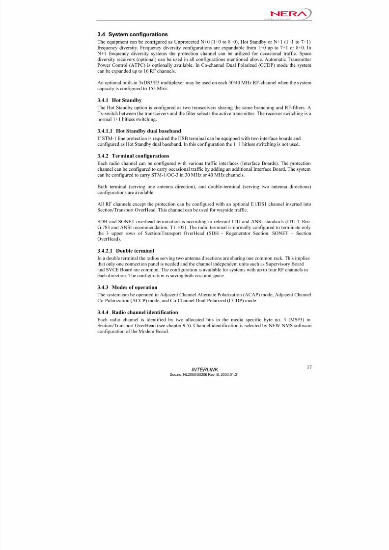
3.4 System configurations
The equipment can be configured as Unprotected N+0 (1+0 to 8+0), Hot Standby or N+1 (1+1 to 7+1)
frequency diversity. Frequency diversity configurations are expandable from 1+0 up to 7+1 or 8+0. In
N+1 frequency diversity systems the protection channel can be utilized for occasional traffic. Space
diversity receivers (optional) can be used in all configurations mentioned above. Automatic Transmitter
Power Control (ATPC) is optionally available. In Co-channel Dual Polarized (CCDP) mode the system
can be expanded up to 16 RF channels.
An optional built-in 3xDS3/E3 multiplexer may be used on each 30/40 MHz RF-channel when the system
capacity is configured to 155 Mb/s.
3.4.1 Hot Standby
The Hot Standby option is configured as two transceivers sharing the same branching and RF-filters. A
Tx-switch between the transceivers and the filter selects the active transmitter. The receiver switching is a
normal 1+1 hitless switching.
3.4.1.1 Hot Standby dual baseband
If STM-1 line protection is required the HSB terminal can be equipped with two interface boards and
configured as Hot Standby dual baseband. In this configuration the 1+1 hitless switching is not used.
3.4.2 Terminal configurations
Each radio channel can be configured with various traffic interfaces (Interface Boards). The protection
channel can be configured to carry occasional traffic by adding an additional Interface Board. The system
can be configured to carry STM-1/OC-3 in 30 MHz or 40 MHz channels.
Both terminal (serving one antenna direction), and double-terminal (serving two antenna directions)
configurations are available.
All RF channels except the protection can be configured with an optional E1/DS1 channel inserted intoSection/Transport OverHead. This channel can be used for wayside traffic.
SDH and SONET overhead termination is according to relevant ITU and ANSI standards (ITU-T Rec.
G.783 and ANSI recommendation: T1.105). The radio terminal is normally configured to terminate only
the 3 upper rows of Section/Transport OverHead (SDH - Regenerator Section, SONET – Section
OverHead).
3.4.2.1 Double terminal
In a double terminal the radios serving two antenna directions are sharing one common rack. This implies
that only one connection panel is needed and the channel independent units such as Supervisory Board
and SVCE Board are common. The configuration is available for systems with up to four RF channels ineach direction. The configuration is saving both cost and space.
3.4.3 Modes of operation
The system can be operated in Adjacent Channel Alternate Polarization (ACAP) mode, Adjacent Channel
Co-Polarization (ACCP) mode, and Co-Channel Dual Polarized (CCDP) mode.
3.4.4 Radio channel identification
Each radio channel is identified by two allocated bits in the media specific byte no. 3 (MS#3) in
Section/Transport OverHead (see chapter 9.5). Channel identification is selected by NEW-NMS software
configuration of the Modem Board.

7/22/2019 Nera Interlink Technical Description
http://slidepdf.com/reader/full/nera-interlink-technical-description 20/58
7/22/2019 Nera Interlink Technical Description
http://slidepdf.com/reader/full/nera-interlink-technical-description 21/58
7/22/2019 Nera Interlink Technical Description
http://slidepdf.com/reader/full/nera-interlink-technical-description 22/58
INTERLINK Doc.no: NL2000\00206 Rev. B, 2003.01.31
20
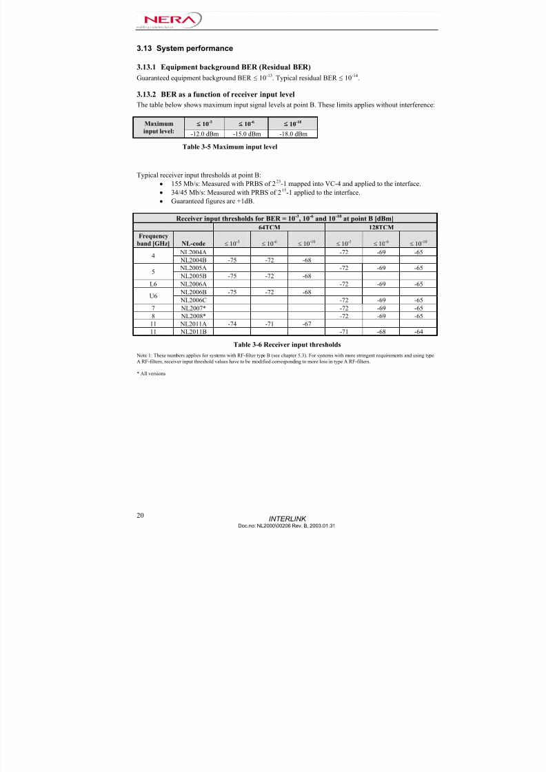
3.13 System performance
3.13.1 Equipment background BER (Residual BER)
Guaranteed equipment background BER ≤ 10-13. Typical residual BER ≤ 10-14.
3.13.2 BER as a function of receiver input levelThe table below shows maximum input signal levels at point B. These limits applies without interference:
10-3 10-6 10-10 Maximum
input level: -12.0 dBm -15.0 dBm -18.0 dBm
Table 3-5 Maximum input level
Typical receiver input thresholds at point B:
• 155 Mb/s: Measured with PRBS of 223-1 mapped into VC-4 and applied to the interface.
• 34/45 Mb/s: Measured with PRBS of 215-1 applied to the interface.• Guaranteed figures are +1dB.
Receiver input thresholds for BER = 10-3
, 10-6
and 10-10
at point B [dBm]
64TCM 128TCM
Frequency
band [GHz] NL-code ≤ 10-3 ≤ 10-6 ≤ 10-10 ≤ 10-3 ≤ 10-6 ≤ 10-10
NL2004A -72 -69 -654
NL2004B -75 -72 -68
NL2005A -72 -69 -655
NL2005B -75 -72 -68
L6 NL2006A -72 -69 -65 NL2006B -75 -72 -68
U6 NL2006C -72 -69 -65
7 NL2007* -72 -69 -65
8 NL2008* -72 -69 -65
11 NL2011A -74 -71 -67
11 NL2011B -71 -68 -64
Table 3-6 Receiver input thresholds
Note 1: These numbers applies for systems with RF-filter type B (see chapter 5.3). For systems with more stringent requirements and using type
A RF-filters, receiver input threshold values have to be modified corresponding to more loss in type A RF-filters.
* All versions

7/22/2019 Nera Interlink Technical Description
http://slidepdf.com/reader/full/nera-interlink-technical-description 23/58
7/22/2019 Nera Interlink Technical Description
http://slidepdf.com/reader/full/nera-interlink-technical-description 24/58
INTERLINK Doc.no: NL2000\00206 Rev. B, 2003.01.31
22
3.13.4.1 Dynamic Fading
The sensitivity to dynamic fading can be represented with the following parameters:
155Mbit/s, about 30 MHz channel spacing
•For a notch speed* up to 100 MHz/s and a BER = 10-4, the InterLink can withstand a notch depth of
at least 16 dB (sweeping in ± half channel spacing).
• For a notch speed* up to 100 MHz/s and a BER = 10-6
, the InterLink can withstand a notch depth of
at least 12 dB (sweeping in ± half channel spacing).
155Mbit/s, 40 MHz channel spacing
• For a notch speed* up to 100 MHz/s and a BER = 10-3
, the InterLink can withstand a notch depth of
at least 17 dB (sweeping in ± half channel spacing).
• For a notch speed* up to 100 MHz/s and a BER = 10-6
, the InterLink can withstand a notch depth of
at least 15 dB (sweeping in ± half channel spacing).
* Maximum selective fading notch-depth changes: ≥ 100 dB/s
3.13.5 System delay
The system delay is 18µs
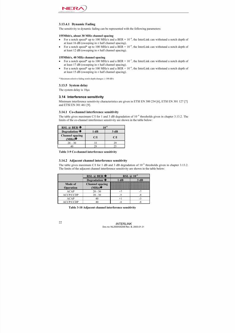
3.14 Interference sensitivity
Minimum interference sensitivity characteristics are given in ETSI EN 300 234 [6], ETSI EN 301 127 [7]
and ETSI EN 301 461 [9].
3.14.1 Co-channel interference sensitivity
The table gives maximum C/I for 1 and 3 dB degradation of 10-6
thresholds given in chapter 3.13.2. The
limits of the co-channel interference sensitivity are shown in the table below:
RSL @ BER 10-6
Degradation 1 dB 3 dB
Channel spacing
(MHz) C/I C/I
28 – 30 33 29
40 29 25
Table 3-9 Co-channel interference sensitivity
3.14.2 Adjacent channel interference sensitivity
The table gives maximum C/I for 1 dB and 3 dB degradation of 10-6 thresholds given in chapter 3.13.2.The limits of the adjacent channel interference sensitivity are shown in the table below:
RSL @ BER RSL @ 10-6
Degradation 1 dB 3 dB
Mode of
Operation
Channel spacing
(MHz) ACAP 28 - 30 +2 -2
ACCP/CCDP 28 - 30 -5 -8
ACAP 40 +1 -3
ACCP/CCDP 40 -4 -8
Table 3-10 Adjacent channel interference sensitivity

7/22/2019 Nera Interlink Technical Description
http://slidepdf.com/reader/full/nera-interlink-technical-description 25/58
7/22/2019 Nera Interlink Technical Description
http://slidepdf.com/reader/full/nera-interlink-technical-description 26/58

7/22/2019 Nera Interlink Technical Description
http://slidepdf.com/reader/full/nera-interlink-technical-description 27/58

7/22/2019 Nera Interlink Technical Description
http://slidepdf.com/reader/full/nera-interlink-technical-description 28/58
7/22/2019 Nera Interlink Technical Description
http://slidepdf.com/reader/full/nera-interlink-technical-description 29/58
7/22/2019 Nera Interlink Technical Description
http://slidepdf.com/reader/full/nera-interlink-technical-description 30/58

7/22/2019 Nera Interlink Technical Description
http://slidepdf.com/reader/full/nera-interlink-technical-description 31/58
INTERLINKDoc.no: NL2000\00206 Rev. B, 2003.01.31
29
7. RECEIVER CHARACTERISTICS
7.1 Receiver input characteristics
For receiver maximum input levels and BER thresholds, see chapter 3.13.2
7.1.1 Local Rx-oscillator tolerance and stability
Frequency tolerance: ± 10 ppm
7.1.2 Receiver image rejection
If image(s) frequency falls within receiver half band ≥ 120 dB
If image(s) frequency falls within transmitter half band ≥ 120 dB
7.1.3 Spurious emissions
7.1.3.1 Spurious emissions - externalThe frequency range in which the spurious emission specifications apply is 9 kHz to 110 GHz
Spurious emissions are below the following levels at reference point C:
Emissions from 9 kHz to 21.2 GHz:
< -50 dBm in any 1 kHz band (from 9 kHz to 150 kHz)
< -50 dBm in any 10 kHz band (from 150 kHz to 30 MHz)
< -50 dBm in any 100 kHz band (from 30 MHz to 1 GHz)
<-50 dBm in any 1 MHz band (from 1 GHz to 21.2 GHz)
Emissions from 21.2 GHz to 110 GHz:
< -30 dBm in any 1 MHz band
7.1.3.2 Spurious emissions - internal
For spurious emissions which fall in the same receiver halfband: < –110 dBm.
7.1.4 Noise figures
Noise figures (F) at point A
Frequency
band [GHz] NL-code
Typical
Noise (F)
[dB]
Guarant.
Noise (F)
[dB]
4 NL2004* 2.5 ≤ 3.0
5 NL2005* 2.5 ≤ 3.0
L6 NL2006A 2.5 ≤ 3.0
U6 NL2006* 2.5 ≤ 3.0
7 NL2007* 2.5 ≤ 3.0
8 NL2008* 2.5 ≤ 3.0
11 NL2011* 2.9 ≤ 3.3
Table 7-1 Noise figure
* All versions
Note: Noise figure at point B is calculated by adding the filter loss (B-A) listed in chapter 5.3 to the noise figure at point A.

7/22/2019 Nera Interlink Technical Description
http://slidepdf.com/reader/full/nera-interlink-technical-description 32/58
INTERLINK Doc.no: NL2000\00206 Rev. B, 2003.01.31
30
8. MODEM CHARACTERISTICS
The Modem Board includes both modulator and demodulator functions on the same circuit board. The
system filtering is equally distributed between transmit and receive side.
IF characteristicsCentre frequency (Tx-direction): 350 MHz
Centre frequency (Rx-direction): 140 MHz
Impedance: 50 Ω, unbalanced
8.1 Modulator
The main functions of the modulator are:
• Signal processing necessary to access OverHead bytes in the SDH/SONET frame
• Digital pulse shaping FIR-filtering
• 64TCM modulation for 155 Mb/s in 40 MHz channel spacing.
• 128 TCM modulation for 155 Mb/s in 30 MHz channel spacing.
Symbol rate - STM-1/OC-3:
• 64TCM: 31.104 Msymbols/s
• 128TCM: 23.9262 Msymbols/s.
8.2 Demodulator
The main functions of the demodulator parts are:
• 64TCM demodulation for 155 Mb/s in 40 MHz channel spacing• 128TCM demodulation for 155 Mb/s in 28-30MHz channel spacing
• Carrier and clock regeneration
• Digital pulse shaping base band-filtering and slope equalization
• Adaptive Transversal Equalizing
• Trellis decoder utilizing the Viterbi algorithm
• Signal processing necessary to access the OverHead bytes in the SDH/SONET frame
8.2.1 Adaptive Time Domain Equalizer (ATDE)
An Adaptive Time Domain Equalizer (ATDE) is provided for each radio channel in order to establish
effective countermeasures against the distortion effects caused by multipath transmission (selectivefading).
The adaptive time domain equalizer has 13 baud-spaced taps and is used to cancel ISI (Inter Symbol
Interference) caused by multi path fading on the radio signal. Additional features are: Adaptive gain,
adaptive quadrature phase error cancellation and adaptive DC-offset error cancellation. It also controls the
demodulation process e.g. by the internal phase detectors for carrier recovery and clock recovery. Clock
recovery uses separate phase detectors on in-phase and quadrature channels. The frequency of clock
recovery PLL, is programmable, enabling multi-modem functionality.
7/22/2019 Nera Interlink Technical Description
http://slidepdf.com/reader/full/nera-interlink-technical-description 33/58

7/22/2019 Nera Interlink Technical Description
http://slidepdf.com/reader/full/nera-interlink-technical-description 34/58

7/22/2019 Nera Interlink Technical Description
http://slidepdf.com/reader/full/nera-interlink-technical-description 35/58
INTERLINKDoc.no: NL2000\00206 Rev. B, 2003.01.31
33
9.5 Section/Transport OverHead (SOH/TOH)
Use of SOH/TOH is according to ITU-T Rec. G.707 and ANSI T1.105.
All X-bytes are reserved for future international standardization according to ITU-T Rec. G.707.
Shaded bytes can be used as a wayside channel
Row\Col 1 2 3 4 5 6 7 8 9
1 A1 A1 A1 A2 A2 A2 J0 N N
2 B1 MS#1 MS#2 E1 X X F1 N N
3 D1 MS#3 X D2 X X D3 X X
4 H1 H1 H1 H2 H2 H2 H3 H3 H3
5 B2 B2 B2 K1 X X K2 X X
6 D4 X X D5 X X D6 X X
7 D7 X X D8 X X D9 X X
8 D10 X X D11 X X D12 X X
9 S1 Z1#2 Z1#3 Z2#1 Z2#2 M1 E2 N N
Table 9-1: Utilization of SOH/TOH-bytes;
9.5.1 Frameword and parity bytes
The first nine bytes in the STM-1/OC-3 frame (row 1 in SOH/TOH) are unscrambled according to ITU-T
Rec. G.707.
• A1: Frameword (11110110)
• A2: Frameword (00101000)
• J0: Regenerator Section Trace (SDH) / Section Trace (SONET)
• B1: BIP-8 (Bit Interleaved Parity-8)
• B2: BIP-24 (Bit Interleaved Parity-24)
Byte 8 and byte 9 in row 1 are reserved for national use and are utilized if the DS1/E1 wayside traffic
option is selected. If not used for DS1/E1 wayside, these bytes shall contain the word 10101010 or
01010101.
9.5.2 Media specific bytes
3 bytes in the SDH/SONET frame (MS#1, MS#2 and MS#3) are used for radio specific purposes:
• MS#1: Radio Protection Switching control
• MS#2: Radio Protection Switching control
• MS#3: RF-id, remote reset, ATPC and E/M-wire for E1, E2 and F1
9.5.3 Other SOH/TOH-bytes
• E1-byte: Orderwire
• F1-byte: User channel, V.11 or G.703 interface optional
• D1-D3 bytes: Embedded Control Channel – Regenerator – ECCr (SDH) / SectionData
Communication Channel (SONET)
• D4-D12 bytes: Embedded Control Channel - Multiplexer -ECC-M (SDH) / SectionData
Communication Channel (SONET)
• E2-byte: Orderwire available when MS-termination (SDH) or Line termination
(SONET) is used
• K1/K2: APS signaling (not used in the radio relay equipment)
• MS-RDI (K2(b6-b8)): Multiplex Section - Remote Defect Indication
• S1 (b5-b8): Synchronization Status Message
7/22/2019 Nera Interlink Technical Description
http://slidepdf.com/reader/full/nera-interlink-technical-description 36/58
INTERLINK Doc.no: NL2000\00206 Rev. B, 2003.01.31
34
• M1-byte: Remote Error Identifier (MS-REI –SDH / REI-Line -SONET)
• B1/B2-byte: BIP-8 / BIP-24
• A1/A2-byte: Frameword
• H1-H3 bytes: Pointer
9.5.4 DS1/E1 wayside traffic
A DS1 or E1 wayside channel can be accommodated using the (33) shadowed bytes shown in Table 9-1
9.5.5 64 kb/s channels
When the DS1/E1 wayside is not used, the shadowed bytes in table 1 can optionally be used as
independent 64 kb/s channels offering V.11 or G.703 interface.
9.6 Specifications of jitter and wander
9.6.1 STM-1/OC-3 traffic interface
Input jitter and wander tolerances are according to ITU-T Rec. G.783. Detailed parameters are given inITU-T Rec. G.958. Output jitter and wander generation is according to ITU-T Rec. G.783. Jitter and
wander transfer are according to ITU-T Rec. G.783.
9.6.2 E3 (34 Mb/s) traffic interface
Input jitter and wander tolerances are according to ITU-T Rec. G.823. Jitter and wander transfer are
according to ITU-T Rec. G.783.
9.6.3 DS3 (45 Mb/s) traffic interface
Input jitter and wander tolerances are according to ITU-T Rec. G.824. Jitter and wander transfer are
according to ITU-T Rec. G.783.
9.6.4 E1 (2.048 Mb/s) wayside interface
Input jitter and wander tolerances are according to ITU-T Rec. G.823. Jitter and wander transfer are
according to ITU-T Rec. G.783.
9.6.5 DS1 (1.544 Mb/s) wayside interface
Input jitter and wander tolerances are according to ITU-T Rec. G.824. Jitter and wander transfer are
according to ITU-T Rec. G.783.
10. SERVICE AND WAYSIDE TRAFFIC
10.1 General
The service channels and the wayside traffic channel are transmitted as parts of SOH/TOH conforming to
ITU-T Rec. G.707 and ANSI T1.105. All electrical digital interfaces conform to ITU-T Rec. G.703 and
ANSI T1.105.06. The analogue orderwire interface conforms to ITU-T Rec. G.711. Pulse Code
Modulation (PCM) of voice frequency is used, using A-law compounding characteristics. Use of DS1/E1
for wayside traffic will limit the number of channels available for other services. The DS1/E1 wayside
channel, the express-telephone and omnibus-telephone and the other 64 kb/s channels are utilizing
SOH/TOH as described in chapter 9.5. The express- and omnibus-telephone will always utilize byte E1,
F1 or E2 for transmission if E&M interface is required.
7/22/2019 Nera Interlink Technical Description
http://slidepdf.com/reader/full/nera-interlink-technical-description 37/58

7/22/2019 Nera Interlink Technical Description
http://slidepdf.com/reader/full/nera-interlink-technical-description 38/58

7/22/2019 Nera Interlink Technical Description
http://slidepdf.com/reader/full/nera-interlink-technical-description 39/58
7/22/2019 Nera Interlink Technical Description
http://slidepdf.com/reader/full/nera-interlink-technical-description 40/58
INTERLINK Doc.no: NL2000\00206 Rev. B, 2003.01.31
38
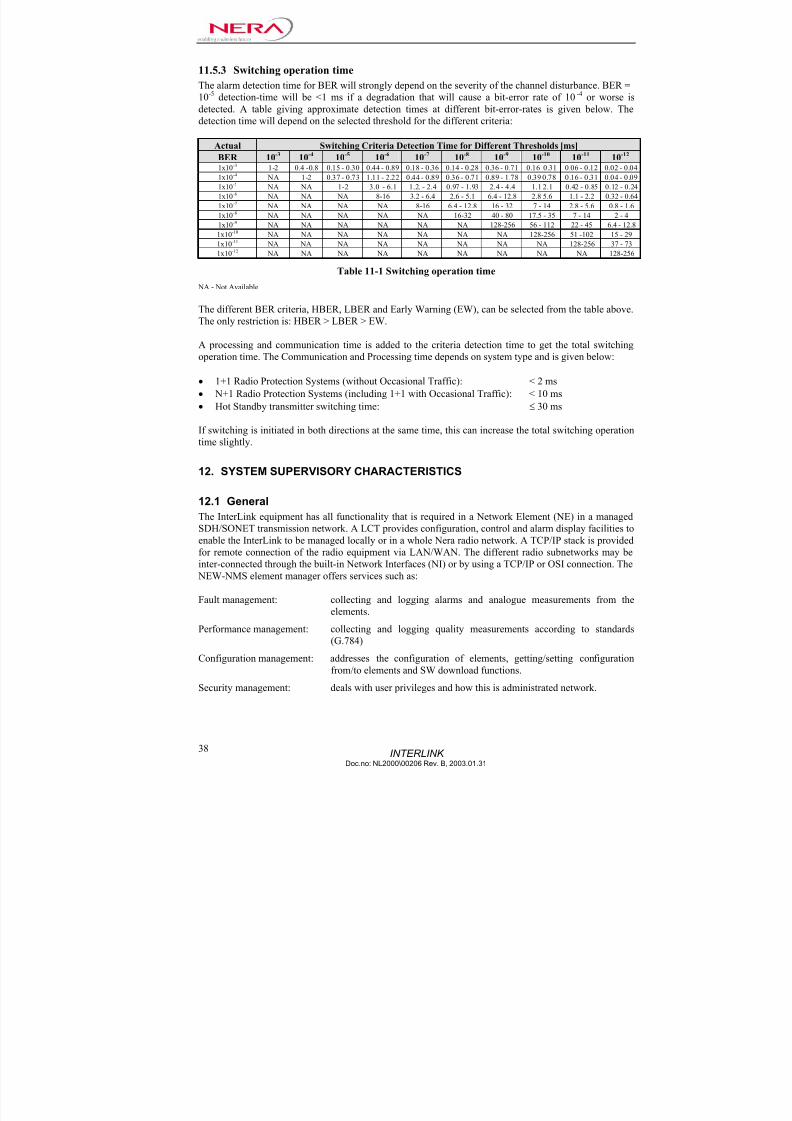
11.5.3 Switching operation time
The alarm detection time for BER will strongly depend on the severity of the channel disturbance. BER =
10-5
detection-time will be <1 ms if a degradation that will cause a bit-error rate of 10-4
or worse is
detected. A table giving approximate detection times at different bit-error-rates is given below. The
detection time will depend on the selected threshold for the different criteria:
Actual Switching Criteria Detection Time for Different Thresholds [ms]
BER 10-3 10-4 10-5 10-6 10-7 10-8 10-9 10-10 10-11 10-12 1x10⁻³ 1-2 0.4 -0.8 0.15 - 0.30 0.44 - 0.89 0.18 - 0.36 0.14 - 0.28 0.36 - 0.71 0.16 0.31 0.06 - 0.12 0.02 - 0.04
1x10⁻⁴ NA 1-2 0.37 - 0.73 1.11 - 2.22 0.44 - 0.89 0.36 - 0.71 0.89 - 1.78 0.39 0.78 0.16 - 0.31 0.04 - 0.09
1x10⁻⁵ NA NA 1-2 3.0 - 6.1 1.2. - 2.4 0.97 - 1.93 2.4 - 4.4 1.1 2.1 0.42 - 0.85 0.12 - 0.24
1x10⁻⁶ NA NA NA 8-16 3.2 - 6.4 2.6 - 5.1 6.4 - 12.8 2.8 5.6 1.1 - 2.2 0.32 - 0.64
1x10⁻⁷ NA NA NA NA 8-16 6.4 - 12.8 16 - 32 7 - 14 2.8 - 5.6 0.8 - 1.6
1x10⁻⁸ NA NA NA NA NA 16-32 40 - 80 17.5 - 35 7 - 14 2 - 4
1x10⁻⁹ NA NA NA NA NA NA 128-256 56 - 112 22 - 45 6.4 - 12.8
1x10⁻¹⁰ NA NA NA NA NA NA NA 128-256 51 -102 15 - 29
1x10-11 NA NA NA NA NA NA NA NA 128-256 37 - 73
1x10-12 NA NA NA NA NA NA NA NA NA 128-256
Table 11-1 Switching operation time
NA - Not Available
The different BER criteria, HBER, LBER and Early Warning (EW), can be selected from the table above.
The only restriction is: HBER > LBER > EW.
A processing and communication time is added to the criteria detection time to get the total switching
operation time. The Communication and Processing time depends on system type and is given below:
• 1+1 Radio Protection Systems (without Occasional Traffic): < 2 ms
• N+1 Radio Protection Systems (including 1+1 with Occasional Traffic): < 10 ms
• Hot Standby transmitter switching time: ≤ 30 ms
If switching is initiated in both directions at the same time, this can increase the total switching operation
time slightly.
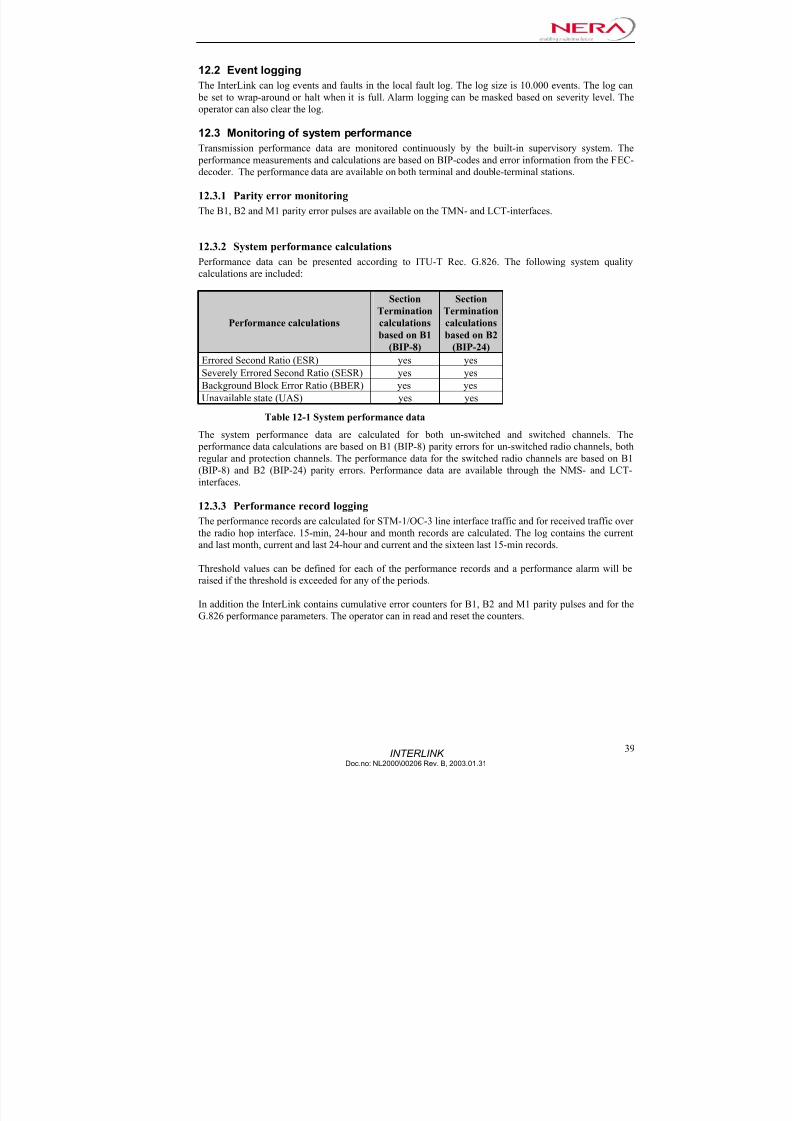
12. SYSTEM SUPERVISORY CHARACTERISTICS
12.1 General
The InterLink equipment has all functionality that is required in a Network Element (NE) in a managed
SDH/SONET transmission network. A LCT provides configuration, control and alarm display facilities to
enable the InterLink to be managed locally or in a whole Nera radio network. A TCP/IP stack is provided
for remote connection of the radio equipment via LAN/WAN. The different radio subnetworks may beinter-connected through the built-in Network Interfaces (NI) or by using a TCP/IP or OSI connection. The
NEW-NMS element manager offers services such as:
Fault management: collecting and logging alarms and analogue measurements from the
elements.
Performance management: collecting and logging quality measurements according to standards
(G.784)
Configuration management: addresses the configuration of elements, getting/setting configuration
from/to elements and SW download functions.
Security management: deals with user privileges and how this is administrated network.
7/22/2019 Nera Interlink Technical Description
http://slidepdf.com/reader/full/nera-interlink-technical-description 41/58

7/22/2019 Nera Interlink Technical Description
http://slidepdf.com/reader/full/nera-interlink-technical-description 42/58
INTERLINK Doc.no: NL2000\00206 Rev. B, 2003.01.31
40
12.4 Security management
The user must have a username and password defined in the InterLink in order to log in. Each user name
is defined with access privileges. Four levels are defined:
User level Privileges
Passive Users Passive users are only able to monitor data. They are not able to collect data or change
the network configuration.
Active Users Active users are able to collect data and change some communication settings, but not
commands that can make unrecoverable configuration changes.
Master Users Master users have access to all NEW-NMS/LCT commands, except those attended
with user account administration.
Admin Users Admin users have access to all NEW-NMSLCT commands. The Admin user is the
administrator and will be responsible for adding, deleting and managing user accounts
and privileges.
12.4.1 Security event logging
The InterLink can log events related to security. The log size is 1000 events. The log can be set to wrap-
around or halt when it is full. The operator can also clear the log.
12.5 ECC (Embedded Communication Channel)
The ECC channel can be configured by the operator. Normally DCC-r (D1 to D3) is used for ECC
purpose but any other available SOH/TOH byte can be used. When DCC-r is used the transmission
capacity is 192 kb/s, if another single SOH/TOH byte is used the transmission capacity is 64kb/s. The
protocol used can be NNP (Nera Networking Protocol), TCP/IP or Qecc. The link layer properties of the
Qecc can be configured by the operator. The routing protocol used for Qecc is IS-IS (ISO 10589)
12.5.1 IP Routing
The InterLink contains a routing function that enables routing of TCP/IP and UDP/IP traffic between the
various management interfaces such as the Ethernet interface and the ECC channel. The routing protocol
used is OSPF (Open Shortest Path First)/RIP2. This enables transport of IP based management protocols
for other telecom equipment over a InterLink path.
12.6 Embedded SNMP agent
The InterLink has an optional embedded SNMP agent, for more information see the separate SNMP MIB
description.

7/22/2019 Nera Interlink Technical Description
http://slidepdf.com/reader/full/nera-interlink-technical-description 43/58
7/22/2019 Nera Interlink Technical Description
http://slidepdf.com/reader/full/nera-interlink-technical-description 44/58
7/22/2019 Nera Interlink Technical Description
http://slidepdf.com/reader/full/nera-interlink-technical-description 45/58

7/22/2019 Nera Interlink Technical Description
http://slidepdf.com/reader/full/nera-interlink-technical-description 46/58
7/22/2019 Nera Interlink Technical Description
http://slidepdf.com/reader/full/nera-interlink-technical-description 47/58
INTERLINKDoc.no: NL2000\00206 Rev. B, 2003.01.31
45
• Service telephone function, four 64 kb/s insertion channels and PABX-adapter, all on the same board.
• Service telephone function and four 64 kb/s insertion channels, not including PABX, on the same
board.
13.1.6 Auxiliary Services Board
The Auxiliary Services Board includes an Alarm Adapter function to facilitate remote control and
external alarm collection, an Alarm Out function to enable parallel output of internal alarms from the
Supervisory Board and an Analogue Input function to enable analogue voltage measurements. The board
contains a µ-Controller for alarm collection and controlling purposes. The µ-Controller is connected to
the supervision system via a bus.
13.1.7 Power Filtering Board
The Power Filtering Board is used to filtering the current flowing into the equipment from the 48V
battery and thereby prevents noise from entering the equipment. The board also includes main power
switch and fuse. This board is always duplicated in multichannel systems to increase the system MTBF.
13.1.8 Alarm Display & Relay Board
The Alarm Display & Relay Board has the following functions:
• LCT connection port
• Four LEDs for Critical, Major/Minor, Warning and Power On
• Relays for the Critical and Major/Minor alarms and for the Warning indicator
• Inventory control, temperature monitoring, voltage reading and alarm collection
13.1.9 Connection Panels
The Connection Panels include board connectors for all circuit boards in the equipment and user interface
connections at the upper part of the panels. The panels are available in two versions depending on the
system configuration.
• A half sized board, Connection Panel Smaller Systems, occupying half the subrack-width suitable for
systems using one or two radios.
• A full size board, Connection Panel Larger Systems, occupying a full subrack suitable for 2+1 and
larger systems.
7/22/2019 Nera Interlink Technical Description
http://slidepdf.com/reader/full/nera-interlink-technical-description 48/58
INTERLINK Doc.no: NL2000\00206 Rev. B, 2003.01.31
46
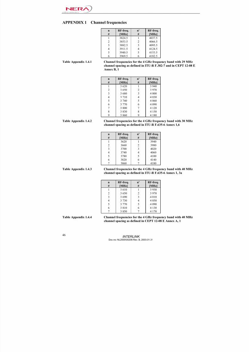
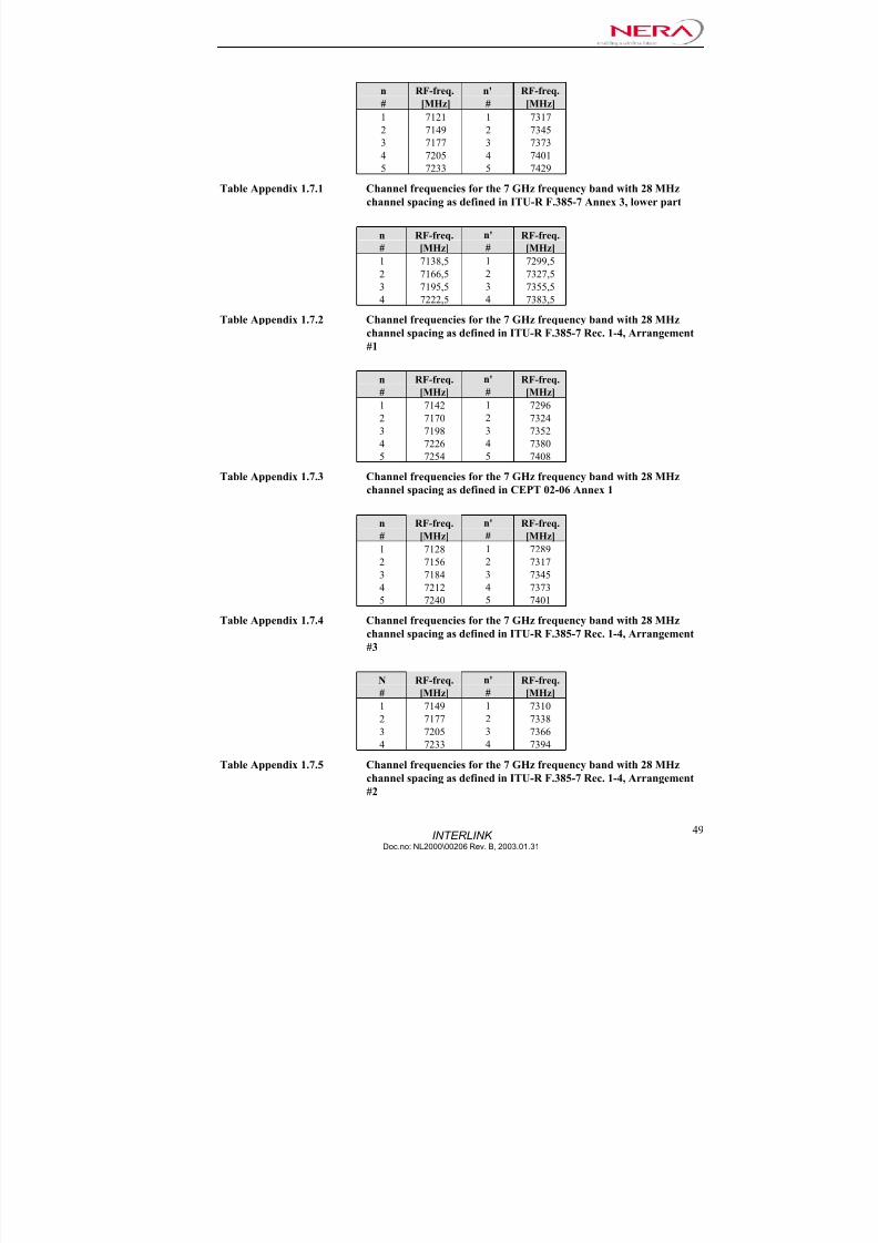
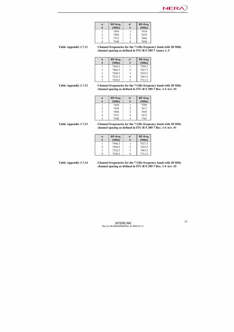
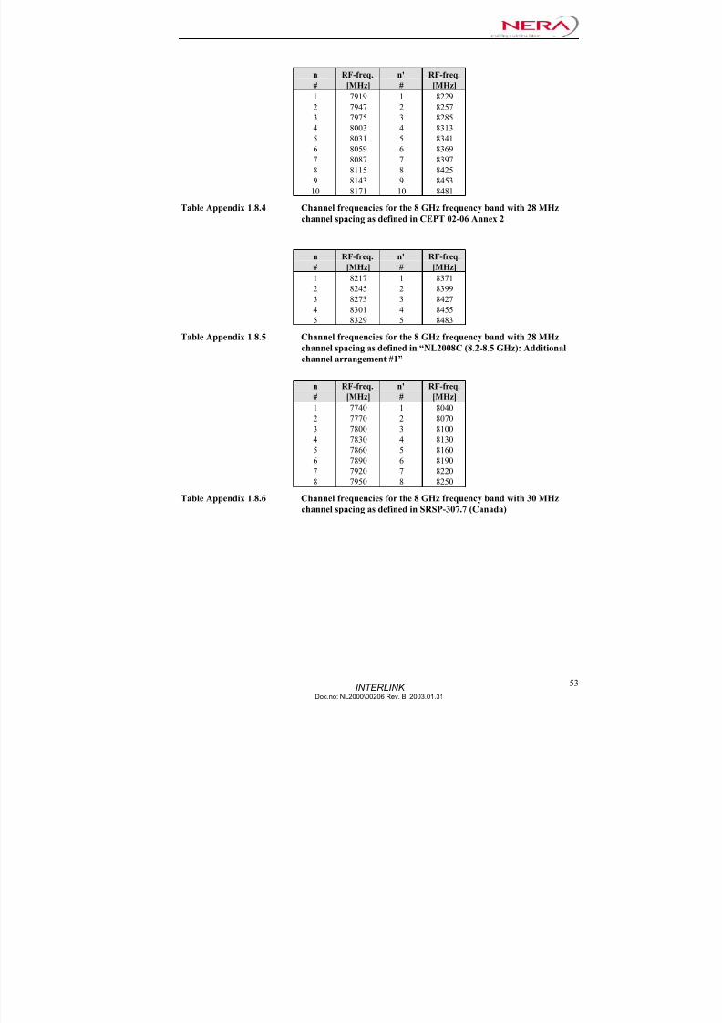
APPENDIX 1 Channel frequencies
n RF-freq. n' RF-freq.
# [MHz] # [MHz]
1 3824.5 1 4037.5
2 3853.5 2 4066.5
3 3882.5 3 4095.5
4 3911.5 4 4124.5
5 3940.5 5 4153.5
6 3969.5 6 4182.5
Table Appendix 1.4.1 Channel frequencies for the 4 GHz frequency band with 29 MHz
channel spacing as defined in ITU-R F.382-7 and in CEPT 12-08 E
Annex B, 1
n RF-freq. n' RF-freq.
# [MHz] # [MHz]
1 3 620 1 3 9402 3 650 2 3 970
3 3 680 3 4 000
4 3 710 4 4 030
5 3 740 5 4 060
6 3 770 6 4 090
7 3 800 7 4 120
8 3 830 8 4 150
9 3 860 9 4 180
Table Appendix 1.4.2 Channel frequencies for the 4 GHz frequency band with 30 MHz
channel spacing as defined in ITU-R F.635-6 Annex 1,6
n RF-freq. n' RF-freq.
# [MHz] # [MHz]
1 3620 1 3940
2 3660 2 3980
3 3700 3 4020
4 3740 4 4060
5 3780 5 4100
6 3820 6 4140
7 3860 7 4180
Table Appendix 1.4.3 Channel frequencies for the 4 GHz frequency band with 40 MHz
channel spacing as defined in ITU-R F.635-6 Annex 1, 3a
n RF-freq. n' RF-freq.
# [MHz] # [MHz]
1 3 610 1 3 930
2 3 650 2 3 970
3 3 690 3 4 010
4 3 730 4 4 050
5 3 770 5 4 090
6 3 810 6 4 130
7 3 850 7 4 170
Table Appendix 1.4.4 Channel frequencies for the 4 GHz frequency band with 40 MHzchannel spacing as defined in CEPT 12-08 E Annex A, 1

7/22/2019 Nera Interlink Technical Description
http://slidepdf.com/reader/full/nera-interlink-technical-description 49/58

7/22/2019 Nera Interlink Technical Description
http://slidepdf.com/reader/full/nera-interlink-technical-description 50/58
7/22/2019 Nera Interlink Technical Description
http://slidepdf.com/reader/full/nera-interlink-technical-description 51/58
7/22/2019 Nera Interlink Technical Description
http://slidepdf.com/reader/full/nera-interlink-technical-description 52/58
INTERLINK Doc.no: NL2000\00206 Rev. B, 2003.01.31
50
n RF-freq. n' RF-freq.
# [MHz] # [MHz]
1 7140 1 7315
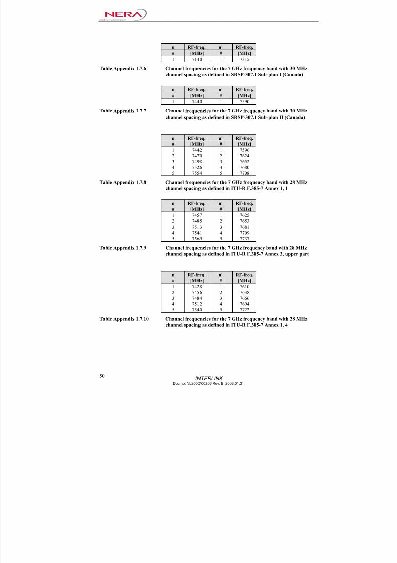
Table Appendix 1.7.6 Channel frequencies for the 7 GHz frequency band with 30 MHzchannel spacing as defined in SRSP-307.1 Sub-plan I (Canada)
n RF-freq. n' RF-freq.
# [MHz] # [MHz]
1 7440 1 7590
Table Appendix 1.7.7 Channel frequencies for the 7 GHz frequency band with 30 MHz
channel spacing as defined in SRSP-307.1 Sub-plan II (Canada)
n RF-freq. n' RF-freq.# [MHz] # [MHz]
1 7442 1 7596
2 7470 2 7624
3 7498 3 7652
4 7526 4 7680
5 7554 5 7708
Table Appendix 1.7.8 Channel frequencies for the 7 GHz frequency band with 28 MHz
channel spacing as defined in ITU-R F.385-7 Annex 1, 1
n RF-freq. n' RF-freq.
# [MHz] # [MHz]1 7457 1 7625
2 7485 2 7653
3 7513 3 7681
4 7541 4 7709
5 7569 5 7737
Table Appendix 1.7.9 Channel frequencies for the 7 GHz frequency band with 28 MHz
channel spacing as defined in ITU-R F.385-7 Annex 3, upper part
n RF-freq. n' RF-freq.
# [MHz] # [MHz]
1 7428 1 7610
2 7456 2 7638
3 7484 3 7666
4 7512 4 7694
5 7540 5 7722
Table Appendix 1.7.10 Channel frequencies for the 7 GHz frequency band with 28 MHz
channel spacing as defined in ITU-R F.385-7 Annex 1, 4
7/22/2019 Nera Interlink Technical Description
http://slidepdf.com/reader/full/nera-interlink-technical-description 53/58

7/22/2019 Nera Interlink Technical Description
http://slidepdf.com/reader/full/nera-interlink-technical-description 54/58
7/22/2019 Nera Interlink Technical Description
http://slidepdf.com/reader/full/nera-interlink-technical-description 55/58

7/22/2019 Nera Interlink Technical Description
http://slidepdf.com/reader/full/nera-interlink-technical-description 56/58
INTERLINK Doc.no: NL2000\00206 Rev. B, 2003.01.31
54
n RF-freq. n' RF-freq.
# [MHz] # [MHz]
1 10715 1 11245
2 10755 2 11285
3 10795 3 11325
4 10835 4 113655 10875 5 11405
6 10915 6 11445
7 10955 7 11485
8 10995 8 11525
9 11035 9 11565
10 11075 10 11605
11 11115 11 11645
12 11155 12 11685
Table Appendix 1.11.1 Channel frequencies for the 11 GHz frequency band with 40 MHz
channel spacing as defined in ITU-R F.387-8 Rec. 1
n RF-freq. n' RF-freq.
# [MHz] # [MHz]
2 10735 2 11265
3 10775 3 11305
4 10815 4 11345
5 10855 5 11385
6 10895 6 11425
7 10935 7 11465
8 10975 8 11505
9 11015 9 11545
10 11055 10 11585
11 11095 11 11625
12 11135 12 11665
Table Appendix 1.11.2 Channel frequencies for the 11 GHz frequency band with 40 MHz
channel spacing as defined in ITU-R F.387-8 Annex 1 and CEPT 12-
06 Rec. 1
n RF-freq. n' RF-freq.
# [MHz] # [MHz]
1 10735 1 11225
2 10775 2 11265
3 10815 3 113054 10855 4 11345
5 10895 5 11385
6 10935 6 11425
7 10975 7 11465
8 11015 8 11505
9 11055 9 11545
10 11095 10 11585
11 11135 11 11625
12 11175 12 11665
Table Appendix 1.11.3 Channel frequencies for the 11 GHz frequency band with 40 MHz
channel spacing as defined in ITU-R F.387-8 Annex 2, CEPT 12-06
Rec. 3, FCC §101.147 (o-7)(US) and SRSP-310.7 (D/D’)(Canada)

7/22/2019 Nera Interlink Technical Description
http://slidepdf.com/reader/full/nera-interlink-technical-description 57/58

7/22/2019 Nera Interlink Technical Description
http://slidepdf.com/reader/full/nera-interlink-technical-description 58/58