THEORY AND MEASUREMENTS OF LABYRINTH SEAL COEFFICIENTS … · THEORY AND MEASUREMENTS OF LABYRINTH...
22
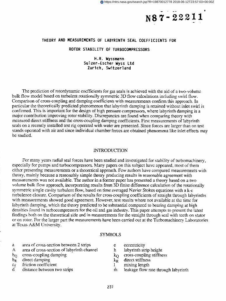
THEORY AND MEASUREMENTS OF LABYRINTH SEAL COEFFICIENTS FOR ROTOR STABILITY OF TURBOCOMPRESSORS H.R. Wyssmann Sulzer-Escher Wyss Ltd Zurich, Switzerland The prediction of rotordynamic coefficients for gas seals is achieved with the aid of a two-volume bulk flow model based on turbulent rotationally symmetric 3D flow calculations including swirl flow. Comparison of cross-coupling and damping coefficients with measurements confirm this approach. In particular the theoretically predicted phenomenon that labyrinth damping is retained without inlet swirl is confirmed. This is important for the design of high pressure compressors, where labyrinth damping is a major contribution improving rotor stability. Discrepancies are found when comparing theory with measured direct stiffness and the cross-coupling damping coefficients. First measurements of labyrinth seals on a recently installed test rig operated with water are presented. Since forces are larger than on test stands operated with air and since individual chamber forces are obtained phenomena like inlet effects may be studied. INTRODUCTION For many years radial seal forces have been studied and investigated for stability of turbomachinery, especially for pumps and turbocompressors. Many papers on this subject have appeared, most of them either presenting measurements or a theoretical approach. Few authors have compared measurements with theory, mainly because a reasonably simple theory producing results in reasonable agreement with measurements was not available. The author in a former paper has presented a theory based on a two volume bulk flow approach, incorporating results from 3D finite difference calculation of the rotationally symmetric single cavity turbulent flow, based on time averaged Navier Stokes equations with a k-e turbulence closure. Comparison of the results for cross-coupling coefficients of straight through labyrinths with measurements showed good agreement. However, test results where not available at the time for labyrinth damping, which the theory predicted to be substantial compared to bearing damping at high densities found in turbocompressors for the oil and gas industry. This paper attempts to present the latest findings both on the theoretical side and in measurements for the straight through seal with teeth on stator or on rotor. For the larger part the measurements have been carried out at the Turbomachinery Laboratories at Texas A&M University. SYMBOLS a area of cross-section between 2 strips A area of cross-section of labyrinth channel bQ cross-coupling damping bR direct damping cf friction coefficient d distance between two strips e eccentricity h labyrinth strip height kk_R cross-coupling stiffness direct stiffness 1 mixing length rh leakage flow rate through labyrinth 237 https://ntrs.nasa.gov/search.jsp?R=19870012778 2018-06-12T23:57:03+00:00Z
Transcript of THEORY AND MEASUREMENTS OF LABYRINTH SEAL COEFFICIENTS … · THEORY AND MEASUREMENTS OF LABYRINTH...
THEORY AND MEASUREMENTS OF LABYRINTH SEAL COEFFICIENTS FOR
ROTOR STABILITY OF TURBOCOMPRESSORS
H.R. WyssmannSulzer-Escher Wyss Ltd
Zurich, Switzerland
The prediction of rotordynamic coefficients for gas seals is achieved with the aid of a two-volume
bulk flow model based on turbulent rotationally symmetric 3D flow calculations including swirl flow.
Comparison of cross-coupling and damping coefficients with measurements confirm this approach. In
particular the theoretically predicted phenomenon that labyrinth damping is retained without inlet swirl is
confirmed. This is important for the design of high pressure compressors, where labyrinth damping is amajor contribution improving rotor stability. Discrepancies are found when comparing theory with
measured direct stiffness and the cross-coupling damping coefficients. First measurements of labyrinthseals on a recently installed test rig operated with water are presented. Since forces are larger than on test
stands operated with air and since individual chamber forces are obtained phenomena like inlet effects maybe studied.
INTRODUCTION
For many years radial seal forces have been studied and investigated for stability of turbomachinery,
especially for pumps and turbocompressors. Many papers on this subject have appeared, most of them
either presenting measurements or a theoretical approach. Few authors have compared measurements withtheory, mainly because a reasonably simple theory producing results in reasonable agreement with
measurements was not available. The author in a former paper has presented a theory based on a two
volume bulk flow approach, incorporating results from 3D finite difference calculation of the rotationally
symmetric single cavity turbulent flow, based on time averaged Navier Stokes equations with a k-e
turbulence closure. Comparison of the results for cross-coupling coefficients of straight through labyrinthswith measurements showed good agreement. However, test results where not available at the time for
labyrinth damping, which the theory predicted to be substantial compared to bearing damping at highdensities found in turbocompressors for the oil and gas industry. This paper attempts to present the latest
findings both on the theoretical side and in measurements for the straight through seal with teeth on stator
or on rotor. For the larger part the measurements have been carried out at the Turbomachinery Laboratories
at Texas A&M University.
SYMBOLS
a area of cross-section between 2 strips
A area of cross-section of labyrinth channel
bQ cross-coupling dampingb R direct damping
cf friction coefficientd distance between two strips
e eccentricity
h labyrinth strip height
kk_R cross-coupling stiffnessdirect stiffness
1 mixing lengthrh leakage flow rate through labyrinth
237
https://ntrs.nasa.gov/search.jsp?R=19870012778 2018-06-12T23:57:03+00:00Z
rh r mass rate exchange between 2 controlvolumes
p pressureQ cross-coupling forceR direct force
r labyrinth radius
Ar radial clearance of concentric labyrintht time
w circumferential velocity
z number of labyrinth strips
[3 mixing factor8 radial clearance of eccentric labyrinth
tx labyrinth flow coefficient
u viscosity
9 density"_ stress
q_ angle
Subscripts:
in inlet
j jetr rotor or radial
s stator
out outlet
THEORY
The theory gives the solution for the circumferential pressure distribution of straight through
labyrinths for gas and (incompressible) hydraulic flow. With some modifications, the theory is alsoapplicable for staggered and full labyrinths. Here only a summary of the theory is given. More detailed
results may be found in [10]. The calculation is based on bulk flow assumptions, i.e. on a uniform flow
profile in the region between the strips and (a different) uniform profile between strip tips and bushing (for
rotor seal) or rotor (for stator seal). This is schematically depicted in Fig. 1. The validity of the assumed
velocity profiles has been confirmed by extensive numeric flow calculations for the rotationally symmetric
3D turbulent flow in a single chamber. In these the velocity field v is decomposed into a time averaged part_ and a turbulent fluctuation part v':
v = _7 + v'. (1)
The continuity equation for v, assuming incompressibilit3' within the chamber, reads after insertion of (1)
and time averaging:
V-7= O.
where V denotes the Nabla Operator.
The time averaged Navier Stokes equations become:
Oq/Ot + (_7.V)_ = - Vp + V_3 x V x _ + turbulent diffusion.
The turbulent diffusion term is described by a two parameter model, based on k = 1/2 v i' v i' , the turbulent
kinetic energy and e = l)0Vl'/Oxi.OVl'/Oxi, the dissipation rate of the kinetic fluctuation energy. For k and
transport equations may be written down with a total of 5 empiric parameters. Correlation of the
parameters to flow measurements has been given by Stoff [8].
As boundary conditions, the pressure difference across the chamber, the rotational speed and the inlet
circumferential velocity are given. The numerical calculations yield the pressure and velocity distributions
(time averaged) within the chamber. The analysis does not consider the flow contraction across the striphowever. The results of this analysis has been used for the modelling of the eccentric quasi-stationary flow
in the labyrinth chamber as given below. The following equations are valid for seals with strips on the
238
rotor, similar equations hold for stator seals. The field equations for the two control volumes in Fig. 1read:
Continuity: a_wi/_( p + 8d_wm/b( p - wmd_8/_ q) - r_A/3t = 0, (2)
a3wi/3_P - mr/p = 0. (3)
Momentum: -2pawi3wil3( p - 2pSdwm3Wm/3 q) - pwm2d38/3¢p ++ l_l(Win - Wout) - arr "_r-
- asr xs - prd3(SWm)/3t- pra3wi/3t = A3p/3cp (4)
-2pawi3wi/3q° + l}lrWo - arr _r -
- dr_j - pra3wi/3t-- a3p/3cp. (5)
Here, the w's denote the circumferential velocity components of the flow: w i the velocity of the core flow
between the strips, w m of the free jet between strip tips and stator and w o the circumferential velocity at the
interface between the two flow regions.
The axial flow is described by the classical leakage equation for the compressible flow through a seal (see
Neumann [6], for instance):
a:n= 2xgrSpo_)'](1 - 7r,p2)/z. (6)
The flow coefficient tx follows the definition of Neumann [6] and takes into account the labyrinth strip
geometry.
The turbulent wall shear stresses are given by
= 1/2 Cfr p Iwi- Wrot [(wi- Wrot) (7)for the rotor, and
"Cs = 1/2 Cfsp'_(Cax 2 + Wm 2 )W m (8)
for the stator, where the friction coefficients Cfr and Cfsare calculated with Prandtl's universal law for thetube flow.
The interaction of the two flow regions is described by a turbulent free shear stress "cjmodelled accordingto Prandtl's mixing length theory:
'l;j = pl 2 lOu/OyIOu/Oy,
where u is the flow velocity in the shear flow zone. For free jets, an obvious chioce for the mixing length 1
is the mixing thickness b (Abramovich [1]). For the obstructed jet flow at hand, a proportionality factor [3is introduced, such that 1 =_b, where _ is a function of the labyrinth geometry. _ has been determined by
correlation of the (bulk flow) solution of the concentric labyrinth to the 3D finite difference calculations of
the rotationally symmetric flow described above and to measurements.
In order to obtain the stiffnes and damping coefficients of the seal, a first order solution of the equations
(2) through (8) in e and 6 is sufficient. Hence, the gap between strips and stator may be written as
where e/Ar _ 1.
as:
8 = Ar + e(t)cos%
The flow quantities and the pressure in equations (2) through (8) may therefore be written
239
7n(q w i = W'-i + _i(q_,t), m = m + ,t),
Wm= Wm + '_m(q0,t), P = P + _(ql,t).
The zeroth order solution describes the concentric labyrinth and has been used to determine the mixing
factor _ by correlation to the 3D finite difference calculations of the rotationally symmetric flow describedabove.
The pressure p(%t), linear in e and e is obtained upon integration of the linearization of equations (2)
through (8). The force components acting on the rotor read:
2n 2n
Q = 0_sinq)rddf, R = ff)cosq_rdd% (9)
with Q orthogonal to and R in line (but opposite) with the rotor eccentricity e. In cartesian coordinates theforce components may be written as:
where kR= stiffness, kQ=the seal.
bQ1Fxl=- - bgj[yj
cross-coupling stiffness, bR= damping, and bQ=
(10)
cross-coupling damping of
For staggered and straight labyrinths, a similar theory may be applied. 3D calculations of the concentric
labbyrinths have shown the circumferential velocity to be almost uniform across the whole chamber here,hence a single circumferential velocity may be assumed [10].
COMPARISON OF CROSS-COUPLING STIFFNESS WITH MEASUREMENTS
The cross-coupling coefficients obtained from the theory as presented above has been compared to
measurements carried out by different authors. It agrees well with the laboratory measurements carried out
by Benckert [2] for various types of labyrinths. The least agreement has been found for staggered and fulllabyrinths. For reference see [10]. Measurements on a real compressor at high pressures with Nitrogen
have been carried out for the first time by the authors company. The circumferential pressure distribution
of the first stage impeller shroud seal in a four stage natural gas compressor designed for a discharge
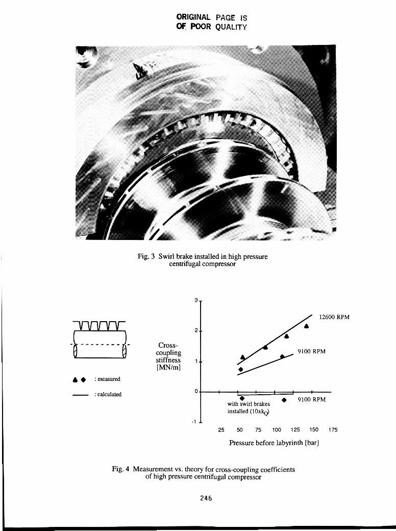
pressure of 320 bar has been measured for different rotor eccentricities relative to the seal. Fig. 2 showsthe test labyrinth in the lower half of the inner casing. The measurements have been carried out with and
without a swirl brake (Fig. 3) to confirm the theoretically predicted influence of the inlet swirl velocity on
cross-coupling stiffness. The circumferential velocity of the leakage flow was measured by pitot tubes in
front of the first labyrinth strip and has been used as inlet condition for the calculation. Fig. 4 shows 'measured and calculated cross-coupling stiffness of the seal for different pressure levels and rotor speeds.
The theory agrees well with measurements. With swirl brake installed, theory gives less negative cross-
coupling than found by measurement. However, the absolute value of the cross-coupling stiffness
compared to the case without swirl brake is very small (scale in Fig. 4 is blown up by factor 10 for case
with swirl brake), hence for practical applications this discrepancy has no importance. All these tests couldnot produce damping coefficients, but they basically confirmed the theoretical approach presented above.
They also confirmed the dominating influence of the inlet swirl velocity on the magnitude of the cross-coupling coefficients and hence were in line with the many cases where rotor stability problems have been
solved by reducing the inlet swirl velocity of the labyrinth leakage flow. The theory however predicts
damping coefficients of labyrinth seals of a magnitude to improve substantially the rotor damping for highpressure compressors. Hence, a confirmation by measurements is of great importance.
240

COMPARISON OF FULL SET OF LABYRINTH COEFFICIENTS WITH MEASUREMENTS
A test rig for air seals has been set up at the Turbomachinery Laboratories of Texas A&M University,
capable to measure the full set of labyrinth coefficients as defined by (10). The rotor is moved by a
hydraulic shaker performing translatory movements. By measuring the reaction forces the dynamiccoefficients can be identified. This differs from the measurements described above, where forces were
obtained by integration of pressures. Extensive measurements have been carded out with straight- through
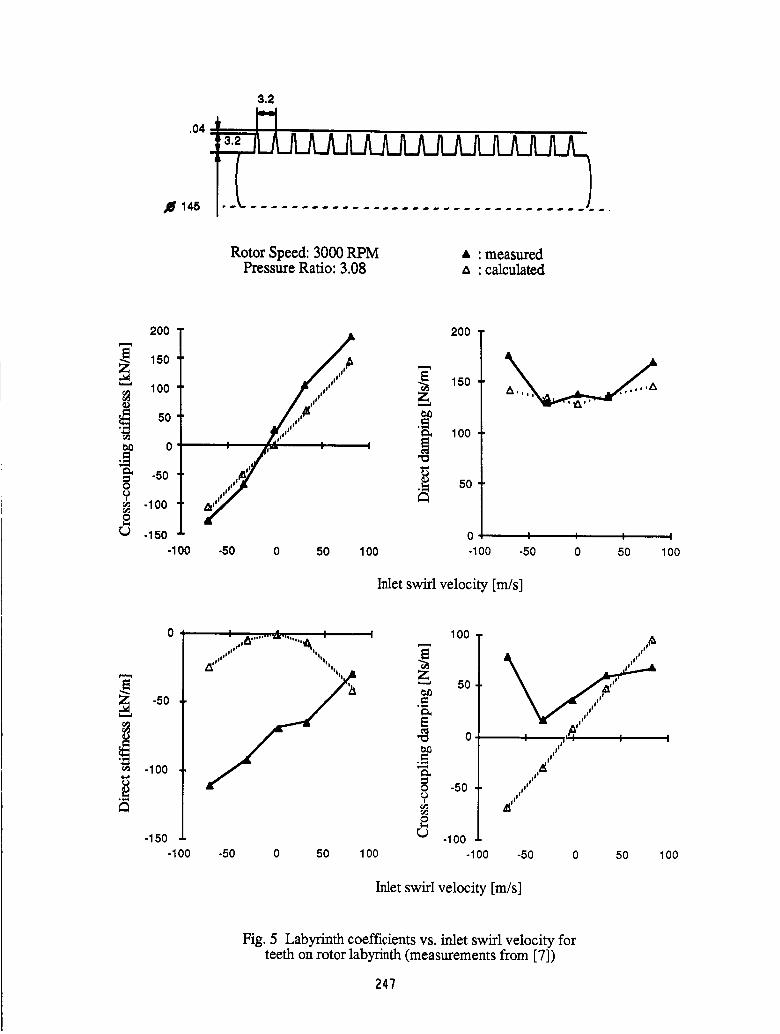
teeth on stator and teeth on rotor labyrinth seals with 16 chambers by Childs and Scharrer ([3], [7]). Rotor
speed varied between 500 and 8000 RPM or 4 m/s to 63 m/s in circumferential velocity, inlet pressuresbetween 3.08 and 8.25 bar (against ambient). Inlet circumferential velocity of the leakage flow could be
varied by employing different inlet guide vanes. Further measurements have been carded out with higher
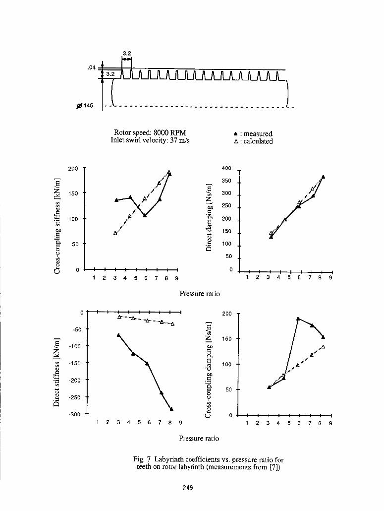
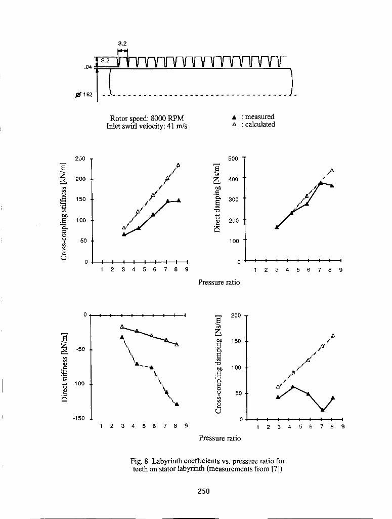
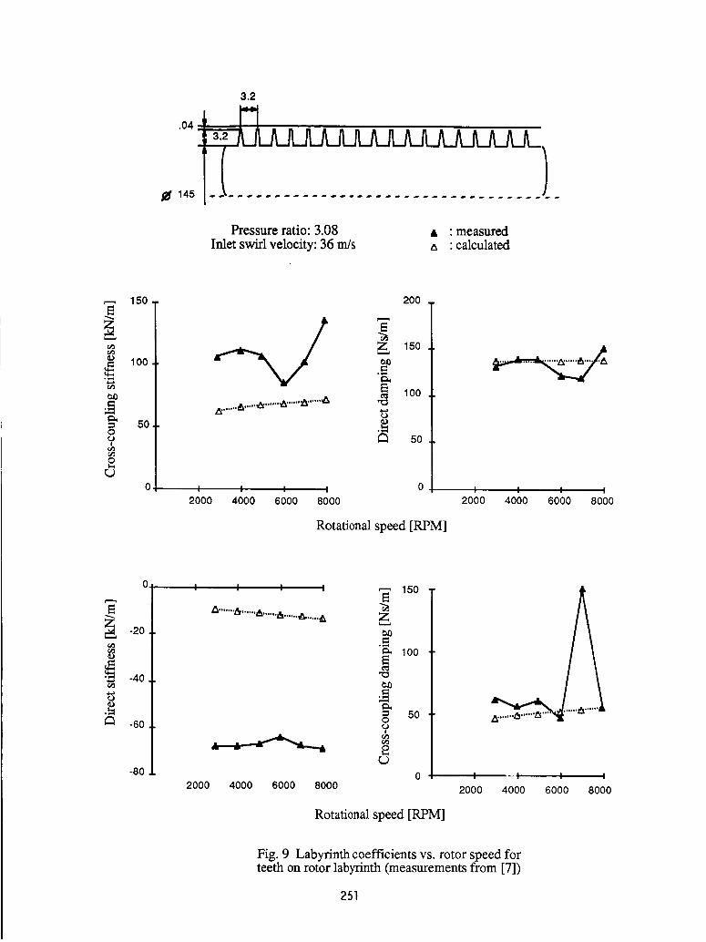
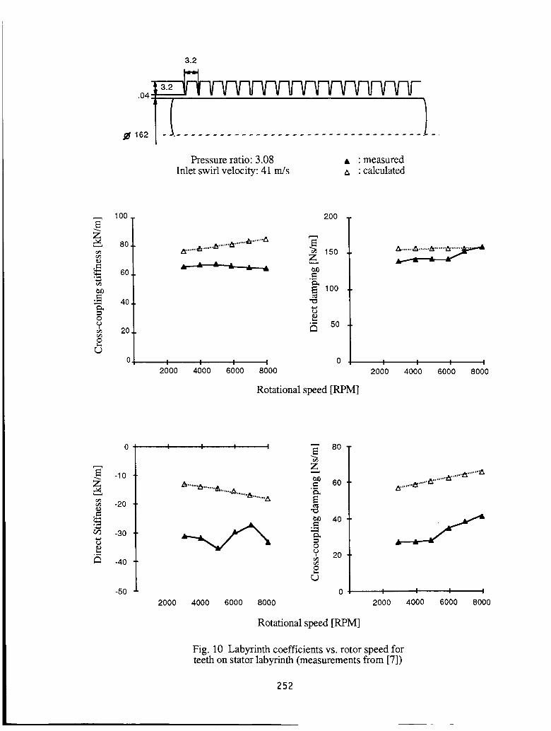
rotor speeds and different labyrinth geometry, but no data has been available until now. Fig. 5 through 10show some of the results taken from [7], together with the theoretical results obtained by the theory
presented above. Agreement of both cross-coupling and damping coefficients with theory for both teeth on
rotor and teeth on stator is more than satisfactory, keeping in mind that a stated experimental uncertainty of7 kN/m for stiffness and 87.5 Ns/m for damping exists. Moreover inlet swirl velocity has not been
measured directly but is calculated by knowing the guide outlet vane corrected by a factor obtained by
guide vane cascade tests. No uncertainty is given here. Also the tested chamber geometry was not exactlymodeled in the theory, theoretical results correspond to a tooth wall angle of 15 ° compared to 6 ° for the
tested labyrinth. Nevertheless, the agreement is reasonably good, especially for the lower pressure ratios
for non-choked flow conditions, which are the more realistic ones in practice. In the case of direct stiffness
the theory gives a completely different dependence on inlet swirl as compared to the measurements. Themeasured coefficients change almost linearly with inlet swirl velocity, whereas theory gives a parabolic
dependence and virtually zero stiffness without swirl. The experimental results are somewhat in contrast toother measurements, namely those by Benckert, where dependence on swirl is similar to that given by
theory. This point has to be investigated further, since the influence of negative labyrinth stiffness on
critical speeds and stability may be substantial, especially for back-to-back compressors with the pistonlabyrinth midspan. Most of the cross-coupled damping measurements are in the order of the given
uncertainty. Theory here gives considerably larger values, at least for high inlet swirl. Moreover, the
dependence _on swirl as given by theory is linear whereas the measurements show little variation.
THE INTRINSIC IDENTITIES OF STATIC AND DYNAMIC COEFFICIENTS
The following simple kinematic reflections show that cross-coupling and direct damping forces are
basically two different representations of the same physical phenomena. This is not further surprising,
since they both have their origin in the fluid dissipation forces. We will further show that if the cross-coupling forces (as functions of inlet swirl velocity) are known, the damping forces can directly bedetermined from them. The same holds {rue for direct stiffness and cross-coupling damping. This implies
then, that if the static forces (i.e. direct stiffness and cross-coupling) are known (for instance by
measurements) for a sufficient range of inlet swirl velocities and with a sufficient accuracy, the dynamic
forces (i.e. direct and cross- coupling damping) can be determined without further measurements. The
above holds true if no centrifugal effects are present, which is generally tacitly assumed (otherwise, forces
on the rotor would be different from those acting on the stator).
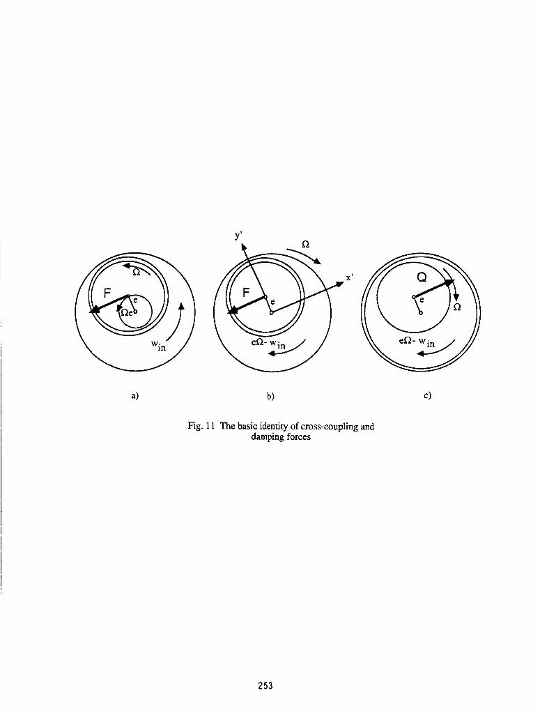
Let us consider a labyrinth with slrips on the rotor (without loss of generality). The rotor has rotational
speed _, eccentricity e and a velocity of the rotor center of fie, i.e. the rotor is rotating around the sealcenter. Let the inlet swirl velocity be Win (see Fig. 1 la). Then the lateral force F acting on the rotor is
given by
241

F = (kQro t - bRrot _)e,
where kQrot is the cross-coupling stiffness and bRrot the direct damping coefficient. Seen from the rotatingreference frame (x',y'), the rotor is stationary, the stator rotates with -f2 and the inlet swirl velocity is -
(Wrot-Win), where Wrot is the circumferential rotor speed (see Fig. 1 lb). With the above assumption i.e no
centrifugal effects, the forces have not changed by the change of coordinates and by the same token we caninterchange rotor and stator without changing the forces (Fig. 1 lc), i.e. we have now a seal with teeth on
stator, static eccentricity e, rotor speed -f2 and inlet swirl velocity -(Wrot-Win ). The force acting on the rotor
is now simply a cross-coupling force kQstate in the opposite direction of F. Setting the two forces equal,we obtain the following equation:
kQrot(Win ) - bRrot (Win) _'2 = - kQstat(Wrot-Win),
or
bRrot(Win) = 1/f2 [kQrot(Win) + kQstat(Wrot-Win)]. (11)
Hence, the damping coefficient is completely determined by cross-coupling coefficients. For stiffness andcross-coupling damping the same reasoning leads to
bQrot(Win) = 1/_ [kRstat(Wrot-Win ) - km.ot(Win)]. (12)
Since both expressions involve differences, the practical value for determining damping coefficients maybe questionable. However, the identities may be used for either a check for measurement accuracy or for
secondary effects not included in the theory. Also it follows from the identities that a theory which predictswell cross-coupling stiffness will also predict damping with the same accuracy and the same is true for the
other two coefficients. Therefore, it is no coincidence that the presented theory performs equally well forcross-coupling and damping.
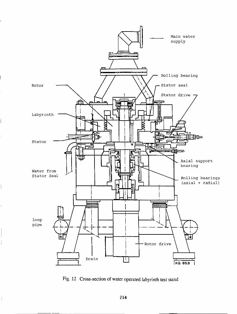
WATER OPERATED TEST STAND FOR ROTORDYNAMIC FORCE MEASUREMENTS
A test rig has been set up at the Institut ftir Fliissigkeitstechnik at the Federal Institute of Technologyin Zurich, Switzerland. It is water operated and was initially designed for the measurements of rotor-
dynamic coefficients of hydraulic seals for pumps and water turbines. Important features of this test rig arethe high measuring accuracy, which allows precise measurements even at zero inlet swirl and low rotor
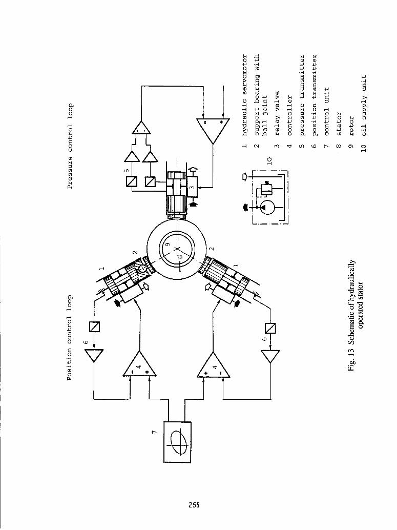
speeds, the seperate measurement of the individual chambers and the hydraulically operated stator,
allowing various orbit configurations, such as circular orbits. Rotor speed varies between 0 and 3570
RPM (i.e. 0 - 67 m/s), pressure up to 8 bar, stator frequency up to 30 Hz. Inlet swirl is either zero or close
to rotor circumferential speed (produced by rotor blades). The pressure distribution is measured in the
individual chambers by static and dynamic pressure probes, inlet swirl velocity by total pressure probes.
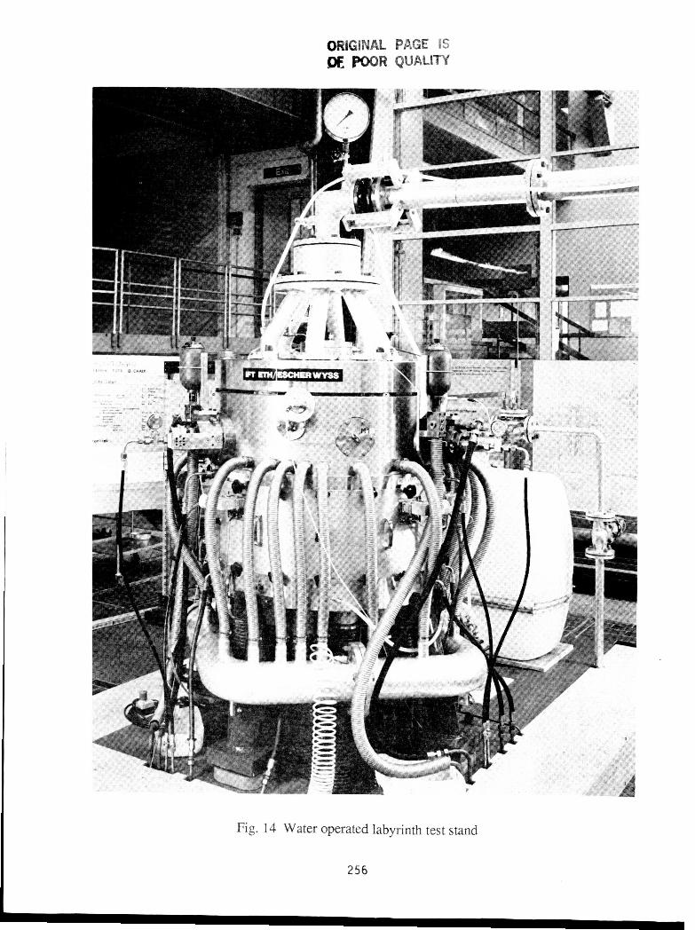
Fig. 12 gives a cross section of the test stand and Fig.13 a schematic of the hydraulic stator drive. Fig. 14shows the test stand after installation (Figures by courtesy of Institut ftir Fliissigkeitstechnik, Federal
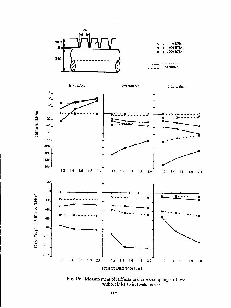
Institute of Technology, Zurich Switzerland). Up to now, only static measurements of direct stiffness andcross-coupling stiffness have been carried out with no inlet swirl. The first measurements have been
carried out with a three chamber straight-through labyrinth seal with teeth on the stator. Fig. 15 shows the
results of the measurements of the different chambers for different pressures and rotor speeds. An
interesting fact is the positive stiffness in the first chamber. It may be explained by the circumferential
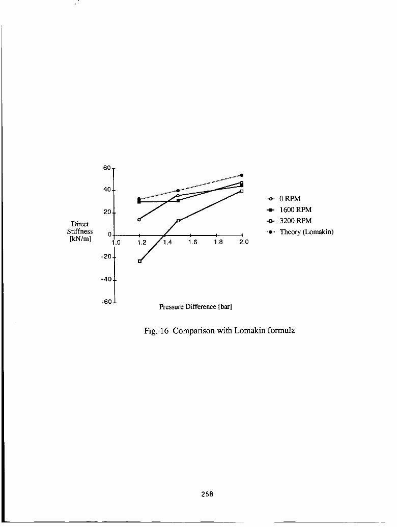
variation of the axial friction losses in an eccentric seal (also called Lomakin effect [4], [5]). For a plainannular seal the centering stiffness coefficient is given by ([9]):
242
k = Ap 7z)_4e,
2Ar2(_.l/2Ar + 1)2
where Ap is the pressure drop along the seal, 1 the length, Ar the radial clearance and _. the pipe flownumber. Considering the first labyrinth chamber as a plain annular seal with clearance equal to tip
clearance, we obtain the values for k very close to the measured direct stiffness (see Fig. 16), at least for
the lower rotor speeds. Hence it seems that for direct stiffness the first chamber acts rather like a plainannular seal. Even in the second and third chamber the direct stiffness shows anomalous behaviour for the
lower rotor speeds, only for high rotor speed is the behaviour as predicted by theory, i.e. a reduction ofthe (negative) stiffness with increasing pressure difference. This reduction is a consequence of the smaller
pick-up of circumferential speed in the chambers with the increase of axial flow with pressure difference.
For gas seals, where the density increases with pressure, the (negative) stiffness increases also (see Fig. 7
and 8). Another interesting feature is the strong dependence of the stiffness on rotor speed as predicted by
theory. This is in contrast to the measurements by Scharrer [7], where stiffness was virtually independentof rotor speed. Cross-coupling stiffness shows an expected negative sign, but it increases from first to
second chamber as opposed to theory. Again, it sems that the first chamber is behaving differentlycompared to the following ones. As in the comparison for the short labyrinth in Fig. 4 for zero inlet swirl,
the theory gives generally larger cross-coupling stiffness (in the algebraic sense) compared to
measurement. Since the cross-coupling forces are very small at zero swirl compared to practical inlet swirl
velocities found in reality (without swirl brakes), this does not impair seriously the theory for predictingrotor stability, as long as damping coefficients are predicted accurately. Further measurements will includedamping coefficients with circular or elliptical orbits of the stator and measurements with inlet swirlvelocity.
CONCLUSIONS
The theoretical prediction of cross-coupling and damping coefficients has been corroborated byseveral independent measurements for different rotor speeds and inlet swirl velocities of the leakage flow,the most important ones being the gas seal tests at the Turbomachinery Laboratories at Texas A&M
University. In particular, it has been shown that the damping coefficients of the seals are behaving as
predicted by theory, i.e. they are insensitive to a wide range of inlet swirl velocities. This has importantconsequences for the design of high pressure centrifugal compressors, where the seals may be considered
as passive dampers for rotor vibrations. For the direct stiffness and the cross-coupling dampingcoefficients, the theory differs largely from measurements, at least for the gas seal measurements from
Texas A&M University. Here, further work is necessary on the theoretical and also on the experimentalside. The water operated test stand presented gives new insights into the behaviour of labyrinth seals due
to its high measuring resolution and the possibility of measuring individual chambers. Further
measurements may show the way how to resolve the discrepancy between theory and measurements fordirect stiffness and cross-coupling damping.
243

REFERENCES
1. Abramovich, G. N., The Theory of Turbulent Jets, MIT Press, Cambridge, Mass., 1963.
2. Benckert, H., ....Spaltstr6mung." ForschungsberichteForschungs-vereinigung
Verbrennungskraftmaschinen," Frankfurt, Vol. 252, 1978.
3. Childs, D. W., and Scharrer, J. K., "Experimental Rotordynamic Coefficient Results for
Teeth-on-Rotor and Teeth-on-Stator Labyrinth Gas Seals," Mechanical Engineering
Department, i'urbomachinery Laboratories, Texas A&M University, College Station,
Texas 77843.
4. de Salis, J., "Lomakin-Effekt bei Durchblicklabyrinthen ?," Interner Bericht 635-9, Institut
fiir Fltissigkeitstechnik, Eidg. Techn. Hochschule, Ztirich, 1984.
5. Lomakin, A. A., "Die Berechnung der kritischen Drehzahl und der Bedingungen ftir
dynamische StabiliNt der L_iufer von Hochdruckstr6mungs- maschinen unter
Berticksichtigung der in der Dichtung auftretenden Krafte (in Russian),"
Energomasinostroenie, Vol. 4, 1958, pp. 1-5.
6. Neumann, K., "Zur Frage der Verwendung von Durchblickdichtungen im
Dampfturbinenbau," Maschinentechnik, Vol. 13, 1964, Nr.4
7. Scharrer, J. K., "A Comparison of Experimental and Theoretical Results for Rotordynamic
Coefficients for Labyrinth Gas Seals," Turbomachinery Laboratories Report No.
SEAL-2-85, Texas A&M University, May 1985.
8. Stoff, H., "Calcul et mesure de la turbulence d'un 6coulement incompressible dans le 1
labyrinthe entre une arbre en rotation et un cylindre stationnaire," Thesis No. 342 (1979)
Swiss Federal Institute of Technology, Lausanne, Juris Verlag Ziirich, 1979.
9. Trutnovsky, K., Beriihrungsfreie Dichtungen, VDI Verlag, 1973.
10. Wyssmann, H., Pham, T. C. and Jenny, R., "Prediction of Stiffness and Damping
Coefficients for Centrifugal Compressor Labyrinth Seals," Journal of Engineering for Gas
Turbines and Power, Vol. 106, 1984, pp. 920-926.
244
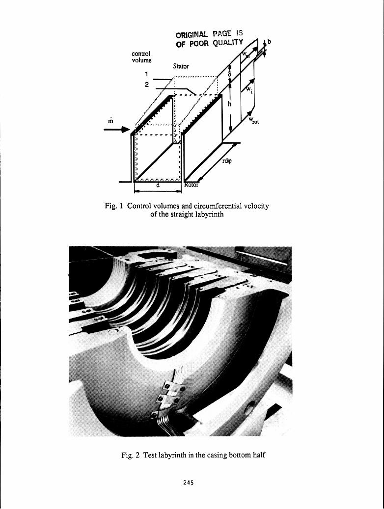
Fig. 1 Control volumes and circumferential velocity of the straight labyrinth
L
I
-- I --_I
Fig. 2 Test labyrinth in the casing bottom half
245
ORIGINAL PAGE IS OF: POOR QUALITY
Fig. 3 Swirl brake installed in high pressure centrifugal compressor
2.
Cross- coupling stiffness I .
- _ - _ - _ _ _ - -
A + n :measured [MN/ml
12600 RPM
9100 RPM
- :calculated O ] ] with swirl brakes
-1 25 50 75 100 125 150 175
Pressure before labyrinth [bar]
Fig. 4 Measurement vs. theory for cross-coupling coefficients of high pressure centrifugal compressor
246
,O4
145
Rotor Speed: 3000 RPMPressure Ratio: 3.08
• "measured,', • calculated
200
150
100
_ 0
_ -50
?-1O0
-150
-100
St"
-50 0 50 100
200
150
_0
"E 100
o_ 50
0 I I I I
-100 -50 0 50 100
Inlet swirl velocity [m/s]
-g-50
_==,a
-I00
-150
-10(
I ......... ._ ..... I
J fl j°fl_ tl=_lil
ill! lilt
',_,,Wli
-50 0 50 100
100
Z5O
ZE
O
?
oEJ
-50
-IO0
-IO0 -50 0 50 100
Inlet swirl velocity [m/s]
Fig. 5 Labyrinth coefficients vs. inlet swirl velocity forteeth on rotor labyrinth (measurements from [7])
247

3.2
.04
Rotor Speed: 3000 RPM • "measuredPressure Ratio: 3.08 _ : calculated
_--_ __2001 _ 200 I
""°°1" /l°°t
-1 O0 ,'"'
r_ -150 _ 0 / ! i i i
-100 -50 0 50 100 -100 -50 0 50 100
Inlet swirl velocity [m/s]
E
o_
0dP
.8
-10
-20
-30
-40
-50
-100
o
r,
-50 0 50 100
E
ZetO
Ec_
¢xo
2r,j
12o'
80.
40.
G
-40 t
-8o
-1oo
____---/
• .- , |
-50 0 50 100
Inlet swirl velocity [m/s]
Fig. 6 Labyrinth coefficients vs. inlet swirl velocity forteeth on stator labyrinth (measurements from [7])
248
.04
3.2
l-1
Rotor speed: 8000 RPMInlet swirl velocity: 37 m/s
• • measuredtx : calculated
200
150
_3
.,-, 100
g_ 50o?
o
r..) 0 : : ! ! ! ; : ! !
1 2 3 4 5 6 7 8 9
400
350
"--- 300Z
250.Ec_ 200
150
._ 100
50
/IJllll"
1 2 3 4 5 6 7 8 9
Pressure ratio
-50
E -i oo
-150
-_ -200
._ -250
-300
, , l : : , I I I
A ........ _ ........ '_' ........&'""_
1 2 3 4 5 6 7 8 9
200
Z 15o
i:::z.,E
100
_ 50o?
o
_ 0 : : : : : : I I I
1 2 3 4 5 6 7 8 9
Pressure ratio
Fig. 7 Labyrinth coefficients vs. pressure ratio forteeth on rotor labyrinth (measurements from [7])
249
3.2
04 3.2
Rotor speed: 8000 RPMInlet swirl velocity: 41 m/s
• • measuredtx • calculated
250
150
.E 1oo
o_, 50r_
o
0
lllll IIII
l ; ! ; ; • : : :
1 2 3 4 5 6 7 8 9
5OO
Z 400
_" 300E
._ 200
IO0
Pressure ratio
ill IIJ
• : • : : : : : :
1 2 3 4 5 6 7 8 9
,_ -5O
¢.)
.,-, -100
-150
• | • , . : ." : ,
1 2 3 4 5 6 7 8 9
200Er_
Z
e_ 150• _,,,i
Ec_
e_ 100
o_, 50
o
Pressure ratio
iii Ip_
Iiiii II1_
1 2 3 4 5 6 7 8 9
Fig. 8 Labyrinth coefficients vs. pressure ratio forteeth on stator labyrinth (measurements from [7])
250
.O4
,_ 145
3.2
3.2
!Pressure ratio: 3.08
Inlet swirl velocity: 36 m/s• • measuredtx "calculated
100
e_o
o?
0
rj
50
o I
2000
2OO
_ 150
Z_ ....&'"'"_ ......'_'"'"_"'"'"_' ,._ 100
50
I I I 04000 6000 8000
Rotational speed [RPM]
I I I I
2000 4000 6000 8000
0
-40
.8_l -60
-8O
I I I I
Z_....... ,_ ...... '_"'""&...... dl,...../_
2000 4000 6000 8000
150H
Z
.,_100
E
bO
0?r._
rj
50
10 I -I I I
2000 4000 6000 8000
Rotational speed [RPM]
Fig. 9 Labyrinth coefficients vs. rotor speed forteeth on rotor labyrinth (measurements from [7])
251
Pressure ratio: 3.08
Inlet swirl velocity: 41 m/s
• • measured,., • calculated
_D
o,.._
e/)
oI.._
o?o_o
100
8O
60,
40,
2O
&......a,......,,h...,..,,_....'''a'''''''A
air - - ,i, ,.
I I I2000 4000 6000
2OO
150Z
loo.8
•_ 50
t 0 t8000 2000
Rotational speed [RPM]
I I I4000 6000 8000
_' -10
v} -20
o,,-i
r_ -3O
I_ -40
-5O
I I I I
""'"'"_" ......_ ,,.. ,,'k, ,,...,&.......
2000 4000 6000 8000
80E
Z_o
._ 60
.8¢_o 40
.=.
o,_ 20
£
. ..,..._,'"'"_
Z%.,,,.,._r,,.,_.......
I I I I
2000 4000 6000 8000
Rotational speed [RPM]
Fig. 10 Labyrinth coefficients vs. rotor speed forteeth on stator labyrinth (measurements from [7])
252
)!
Xv
a) b) c)
Fig. 11 The basic identity of cross-coupling anddamping forces
253
Main water
supply
Rotor
Labyrinth
Stator
Water from
Stator Seal
loop
pipe
II
Rolling bearing
Stator seal
Stator drive
Axial support
bearing
Rolling bearings
(axial + radial)
Fig. 12 Cross-section of water operated labyrinth test stand
254
\ /
0 _
_o
r_
,e-,,l
4----
255
ORIGINAL PAGE IS LOF, POOR QUALITY
Fig. 14 Water operated labyrinth test stand
256
24
360_
o : 0 RPM[] : 1600 RPM
• : 3200 RPM
: measured
.... : calculated
1st chamber
60.
of20
-20.
-40.
-60.._
-80
-100
-120,
-140.
-1601.2 1.4 1.6 1.8 2.0
2nd chamber
1.2 1.4 1.6 1.8 2.0
3rd chamber
•-'----0 - -P -0- =-- - -P- - -0
1.2 1.4 1.6 1.8 2.0
20.
0
E
-20.
-4o
"= -60r./3
¢J)
_.E -8o
O
-100
r_ -120
-140
I I I I I
[]" --- _3 ...... =113
°
I_ - --4 ....... •
1.2 1.4 1.6 1.8 2.0
I I I I I
13.' = - - r= ....... []
--aB..
1.2 1.4 1.6 1.8 2.0
I I I I I
4,1
1.2 1.4 1.6 1.8 2.0
Pressure Difference [bar]
Fig. 15: Measurement of stiffness and cross-coupling stiffnesswithout inlet swirl (water tests)
257
DirectStiffness
[kN/m]
60
40
20.
0
1.0
-20,
.o..o,_
!
.....
--o- 0RPM
-m- 1600 RPM
-o- 3200 RPM
•o.. Theory (Lomakin)
-40
-60Pressure Difference [bar]
Fig. 16 Comparison with Lomakin formula
258