The wear mechanisms occurring in a labyrinth seal ...
21
HAL Id: hal-02135086 https://hal.archives-ouvertes.fr/hal-02135086 Submitted on 21 May 2019 HAL is a multi-disciplinary open access archive for the deposit and dissemination of sci- entific research documents, whether they are pub- lished or not. The documents may come from teaching and research institutions in France or abroad, or from public or private research centers. L’archive ouverte pluridisciplinaire HAL, est destinée au dépôt et à la diffusion de documents scientifiques de niveau recherche, publiés ou non, émanant des établissements d’enseignement et de recherche français ou étrangers, des laboratoires publics ou privés. The wear mechanisms occurring in a labyrinth seal/abradable contact depending on the incursion depth parameter Corentin Delebarre, Vincent Wagner, Jean-Yves Paris, Gilles Dessein, Jean Denape, Julien Gurt-Santanach To cite this version: Corentin Delebarre, Vincent Wagner, Jean-Yves Paris, Gilles Dessein, Jean Denape, et al.. The wear mechanisms occurring in a labyrinth seal/abradable contact depending on the incursion depth parameter. Mechanics & Industry, EDP Sciences, 2016, 17 (6), pp.601-620. 10.1051/meca/2015118. hal-02135086
Transcript of The wear mechanisms occurring in a labyrinth seal ...

HAL Id: hal-02135086https://hal.archives-ouvertes.fr/hal-02135086
Submitted on 21 May 2019
HAL is a multi-disciplinary open accessarchive for the deposit and dissemination of sci-entific research documents, whether they are pub-lished or not. The documents may come fromteaching and research institutions in France orabroad, or from public or private research centers.
L’archive ouverte pluridisciplinaire HAL, estdestinée au dépôt et à la diffusion de documentsscientifiques de niveau recherche, publiés ou non,émanant des établissements d’enseignement et derecherche français ou étrangers, des laboratoirespublics ou privés.
The wear mechanisms occurring in a labyrinthseal/abradable contact depending on the incursion
depth parameterCorentin Delebarre, Vincent Wagner, Jean-Yves Paris, Gilles Dessein, Jean
Denape, Julien Gurt-Santanach
To cite this version:Corentin Delebarre, Vincent Wagner, Jean-Yves Paris, Gilles Dessein, Jean Denape, et al.. Thewear mechanisms occurring in a labyrinth seal/abradable contact depending on the incursion depthparameter. Mechanics & Industry, EDP Sciences, 2016, 17 (6), pp.601-620. �10.1051/meca/2015118�.�hal-02135086�
Open Archive Toulouse Archive Ouverte (OATAO) OATAO is an open access repository that collects the work of some Toulouse
researchers and makes it freely available over the web where possible.
This is an author's version published in: https://oatao.univ-toulouse.fr/23599
Official URL : https://doi.org/10.1051/meca/2015118
To cite this version :
Any correspondence concerning this service should be sent to the repository administrator:
Delebarre, Corentin and Wagner, Vincent and Paris, Jean-Yves and Dessein, Gilles and Denape, Jean and Gurt-Santanach, Julien The wear mechanisms occurring in a labyrinth seal/abradable contact depending on the incursion depth parameter. (2016) Mechanics & Industry, 17 (6). 601-620. ISSN 2257-7777
OATAO Open Archive Toulouse Archive Ouverte

The wear mechanisms occurring in a labyrinth seal/ abradable contact depending on the incursion depth parameter
C. DELEBARRE1•2•\ V. WAGNER2, J.Y. PARIS2 , G. DESSEIN2 , J. DENAPE2
AND J. GURT-8ANTANACH1
1 TURBOMECA, Avenue Joseph Szydlowski, 64510 Bordes, France 2 Universite de Toulouse, Laboratoire Genie de Production, Ecole Nationale d 'lngenieurs de Tarbes, 47 Avenue d 'Azereix,
BP 1629, 65016 Tarbes Cedex, France
Abstract - The contact behavior of an abradable coating (Al-Si 6%) and a labyrint h seal tooth (stainless steel) in a t urbo-engine application was studied as a function of the incursion depth parameter, during labyrinth seal/abradable interaction. A controlled and a gradual increase of t he labyrinth seal incursion (by step of 50 µm) is performed to obtain the chronological contact evolution under severe operating tribological conditions. The labyrinth seal/abradable contact experiments were conducted on a dedicated test rig able to reach high contact speeds from 0 to 130 m.s-1
. To complete contact forces measurement during tests, a suitable instrumentation (acoustic emission sensor, accelerometer, thermocouples, etc.) is developed and coupled as close as possible of the interaction area. The experimental results from the both severe tribological conditions are presented by an analysis of signals recorded during contact tests. Macrographic and micrographic rub-groove observations of post tests samples, coupled with recorded signals from the contact complete t he Al-Si 6% behavior study. A wear process description using the third body approach has been proposed to sum up the whole tribological results. Two different varieties of particles product ion have been ident ified; a ductile and an adhering layer on the rub-groove bottom and pulverulent fine powder particles, thus providing two different kind of third body and two different m aterial flows.
Key words: Labyrinth seal / abradable coating / wear mechanisms / third body / experimental study
1 Introduction
T he clearance minimization between rotary parts and stationary parts in turbo-engine air systems is a method, developed by the turbo machinery manufacturers, to improve the turbo-engine efficiency by a precise control of the airflow direction [1,2]. In the secondary air and sealing systems, the control of pressure differences and the levels of cooling between the engine modules are crucial to the turbo-engine operation. During operation, a turboengine is subjected to successive start and stop cycles, thermal expansion, vibration, mechanical loading, which might create rotor-stator displacements and producing undesirable interactions [3,4]. The clearances between dynamic sealing systems of rotating and stationary components have always been important in controlling leakage, and if the clearance is too small, a rub may occur which may damage one or both members. These dynamic sealing
a Corresponding author: corentin .delebarre~enit.fr
systems are composed of a particular type of rotary seal, called the labyrinth seal. This rotary seal controls the cooling airflow through the heated section of the engine. The labyrinth seal is a non contacting circumferential seal located primarily on the rotating shafts between the compression stages and are composed of several annular teeth. They are integral parts of the motor shaft [5], in which a tortuous flow path between the stationary and rotating parts creates a series of pressure drops to reduce the leakage and maintains the pressure balance on the rotor shaft system. Minimal seal clearance is necessary to achieve a labyrinth seal effectiveness and is controlled by the use of an abradable material (rub tolerant material) coated on the housing support. To protect the rotating/stationary parts during undesirable interactions and precisely of incursions of the labyrinth teeth onto bare metal, the insertion of an abradable material layer a few millimeters thick on the housing support has been widely recognized as a robust solution. The turbo-engine housing is coated with a sacrificial abradable material that is thermally sprayed and is composed of a metal phase and a self-lubricating

Nomenclature
AE Acoustic Emission
D Abradable flow, mm3.s−1
Dp Incursion depth, μm
F Feed-rate, mm.rev−1
FFT Fast Fourier Transform
fn Normal force component, N
ft Tangential force component, N
fr1 Test series No. 1 rotational frequency, Hz
fr2 Test series No. 2 rotational frequency, Hz
L Rubbed length, mm
Nb Number of labyrinth seal rotation, rev
R1 Internal radius of the tube coated with
abradable, mm
R2 Radius of the labyrinth seal tooth, mm
STFT Short-Time Fourier Transform
t Interaction time, s
Vinc Labyrinth seal incursion speed, mm.s−1
Vr Labyrinth seal rotational speed, rpm
Vt Labyrinth tip speed, m.s−1
α Contact angular length, rad
μ Friction coefficient
ξ Mechanical clearance, μm
Ω Labyrinth seal angular velocity, rad.s−1
Al-Si-polyimide, Cu-Sn-Bi, Cu-Sn-Pb) subjected to anunlubricated contact with a four teeth labyrinth sealand using a specific full-scale test rig. Additional experi-ments developed by Sulzer Innotec and Sulzer Metco [19]use a specific test rig adapted to the application oflabyrinth/abradable interactions which consists of an al-loy disc that accommodates four continuous seal trips onthe outer circumference, a movable specimen coated withan abradable material and a heating device.
The present study is based on a first assessment ofhigh-speed mechanical interactions between an Alloy 718labyrinth seal and an abradable Al-Si 6% coating initiatedby Delebarre et al. [20], in which an original test rig wasspecifically designed to simulate these interactions in real-istic operating conditions. The test rig has been speciallyinstrumented to allow contact forces, temperature, accel-eration and acoustic emission measurements for a highfrequency analysis of the Al-Si 6% wear mechanism sub-jected to labyrinth seal tooth interactions. Physicochem-ical, mechanical properties and experimental interactiondata were considered to establish relationships betweenthe Al-Si 6% wear behavior and microstructural charac-teristics. According to study conducted by Hase et al. [21],an interpretation of the acoustic emission data have beenperformed using a time-frequency analysis of the interac-tion to identify the specific frequency signatures associ-ated to the Al-Si 6% wear mechanisms encountered [21].The use of a time-frequency representation (the shorttime Fourier transform) enables the identification of ac-tive frequencies during the interaction [22]. A third bodyapproach was considered for a more complete descriptionof the whole wear mechanisms through the concept oftribological circuit.
2 Contact experiments and materials
2.1 Test rig description
A new high-speed test rig was designed to simu-late the interaction between labyrinth seals and abrad-able coatings in similar turbo-engine operating conditions(Fig. 1a). As this test rig design and its special con-tact forces instrumentation have been fully detailed inreference [20], this section essentially describes the mainfeatures and technical improvements used in the follow-ing study. The capabilities of a 5-axis UCP600 VARIOmilling machine from Mikron are used to simulate theturbo-engine interactions between the labyrinth seals andabradable coatings in realistic operating conditions. Thespecificity of the 5-axis milling machine lies in the factthat it is fitted with a unique magnetic bearings spindlewhich allows a maximum rotation speed of 40 000 rpm,corresponding to a tangential contact speed ranged from0 of 130 m.s−1. The test rig is primarily composed ofa labyrinth seal sample representative of an actual mo-tor shaft section part which is shrinking on a HSK-50tool holder instead of a cutting tool. The labyrinth sealsample contact is performed inside a special tube samplecoated in the inner periphery with abradable materials
non-metal phase that provide a high porosity rate and of-fer a good balance between the abradability and erosion resistance [6]. The use of this type of abradable coating is widespread in other extensively researched turbo-engine applications such as use in blade tips and compressor housing [7, 8] and has encouraged turbo-engine manufac-turers to characterize the abradable behavior subjected to rotor-stator interactions.
Today, the research activities are mainly focused on experimental and numerical studies helping to charac-terize the aerodynamics seal performance and leakage level generated by rub-grooves left by the labyrinth seal teeth [9–11]. The effect of the clearance on leakage, the effect of tooth profiles, of tooth thickness, of the geome-try of the labyrinth seal design and on the rub-groove, on labyrinth seal performance have been quantify [12–15]. Concerning the abradable coating behavior during the labyrinth seal interaction, and specially focus on the con-tact understanding, different kinds of test rigs have been developed. A full-scale facility based on a grinding ma-chine has been developed to study the behavior of abrad-able materials (mica filled tetrafluoroethylene (TFE), sil-icone rubber, aluminium polyester and nickel graphite) in contact with a labyrinth seal at relative speeds up to 25 m.s−1 and 130 m.s−1 respectively [16, 17]. The au-thors established a “good abradability” condition for the tested materials by defining a ratio corresponding to the depth of the groove divided by the material loss of the labyrinth. An additional condition describing abradability was defined by Mutazim et al. [18] by characterizing the rub-groove geometry of seven abradable materials (alu-minium, Al-bronze, Al-Si-polyester, Al-bronze-polyester,

(a)
R, : Abradable coating inner radius
R,: Labyrinth seal tip radius
Op : Incursion depth
d : Radial length displacement
F N : Normal force component
~ : Interaction area
D : Abradable coated area
D : Labyrinth seal angular velocity
( : Radial mechanical clearance
a : Contact angular length
i : Maximal interaction depth point
F, : Tangential force component
D : Labyrinth seal sample
(b)
Fig. I. (a) Test rig overview without protective shield cover, (b) simplified dynamic model of the interaction.
representative of the turbo-engine housing facing the labyrinth seals in the secondary airflow section of a turboengine. The labyrinth seal sample is precisely positioned inside the tube to minimize the default concentricity during the interactions. The dynamic properties of the machine tool table actuator achieve a radial incursion speed range of 0.001 mm.s-1 to 25 mm.s-1 fixed by an incursion depth and mechanical clearance based on the real engine conditions.
T he contact between a labyrinth seal and an abradable coating is theoretically characterized by an interaction area induced by the radial incursion of a circular tooth in a tube (Fig. l b). We consider a simplified dynamic model consisting of a stationary tube coated with an abradable material (housing support + abradable coating) of radius R1 and a concentric labyrinth seal sample with a tooth tip of radius R2. The mechanical clearance between the labyrinth seal tooth tip and the abradable coating at rest is equal to ( = R 1 - R2. T he contact interaction is produced by a sudden radial displacement of the abradable sample center (Oi) relative to the rotor center (02). This radial displacement is defined by a target length d and an incursion speed V inc• The interaction area is then characterized by an incursion depth Dp and a contact angular length a. T he contact angular length is easily obtained from Figure 1 b as:
a = 2x (II -arcos ( (((R2 - R1) + Dp)2 + Ri - R~) )) 2 x R1 x ((R2 - R1) + Dp))
(1)
In order to precisely investigate the abradable coating behavior in contact with the labyrinth teeth tip, the test rig configuration was modified with respect to the fullscale configuration. This modification mainly concerned the labyrinth seal specimen design. The labyrinth seal sample geometry has been simplified and is composed of a single circular tooth that is 65.8 mm in external diameter (Fig. 2a). T his labyrinth seal sample configuration simplifies the interaction area and eliminates the juxtapose teeth interaction effects on a single labyrinth seal, such as thermal confinement or different contact behaviors induced by a rotor unbalance. The labyrinth seal tooth of trapezoidal section remains unchanged (Fig. 2b). The trapezoidal section of the labyrinth seal tooth induces a complex contact geometry which evolves according to the incursion depth. T he machining precision of the labyrinth seal teeth (the geometric tolerances and unbalance) , the positioning precision of the test pieces and the spindle stiffness (hypothesized to be infinite during contact) , have an important effect on the mechanical clearance when the rotor is spun up at a rotational speed fl.
A special instrumentation has been developed on the test rig to provide additional macroscopic and microscopic data focused on the abradable behavior during the interactions. First, a simple voltage circuit has been set up to identify the contact time between the labyrinth seal tooth and the abradable coating to avoid the labyrinth seal incursion depth imprecision during tests (Fig. 3a). Actually, an acquisition device records the voltage variations during the tests induced by the opening and closing of the

(a)
Labyrinth sea l sample
(b)
Fig. 2. (a) Labyrinth seal sample design, (b ) labyrinth seal tooth geometry.
Rotating collector ~ 10V
- +
(a)
Labyrinth
Contact area
Abradable coating
Total incursion time s.----r---r---..----..----"T"""--...----,
Constant contact ~
Contact instability
Transient contact
0 10 20 30 40 Time (s)
50 60
(b)
F ig. 3. (a) Schematic diagram of the voltage circuit, (b) typical interaction voltage signal after dynamic filtering.
circuit according to the labyrinth seal tooth contact and abradable coating. A dynamic filter is developed to reduce the undesirable electromagnetic disruptions caused by the magnetic bearing spindle use (Fig. 3b).
Additional sensors a re settled on the abradable test sample as close as possible of the interaction area to complete the study (Fig. 4) . A single axis accelerometer ICP 352C03 from PCB Piezotronics is fixed to the abradable sample to record low-frequency vibration phenomena at a sampling frequency of 15 kHz.
To complete the vibration study and most significantly to record the t ransient elastic waves due to local micro-displacements within the abradable material [23], a high-frequency acoustic emission sensor Micro80 from MISTRAS Group records continuously at a sampling frequency of 1 MHz. Finally, a thermocouple is located in the abradable sample at the abradable/substrate interface to record the temperature evolution during the experiment. All the sensor records are synchronized simultaneously using an autonomous NI CompactDAQ 9138 fitted with the appropriate acquisition devices. All these sensors add
up to the special contact force instrumentation developed to record the interaction forces during the tests.
The control current signals of the magnetic bearings spindle are recorded and processed as values of the contact forces. The processing is the result of a preliminary study designed to calibrate the recorded signals using a Kistler type 9272 dynamometer. The force measurements are based on the calculation of the normal and tangential components of the overall forces applied on the labyrinth seal sample. Details of the special instrumentation were discussed in the previous study and will not be repeated here. Figure 5 presents the superimposition of the typical signals recorded during a low incursion speed interaction.
2.2 Test materials
The labyrinth seal sample used for this test campaign is made of a stainless steel X5CrNiCuNb 17-04 and its chemical composition is presented in Table 1.
The Al-Si 6% abradable coating is thermally sprayed inside the housing support and precisely onto a bond coat

9
<-t-</) 28
_g_ 18
C 8 0 - 2 ~ Gi - 12 1l - 22
--f. __ ft
5
F ig. 4 . Side view of the housing support instrumented.
Voltage J' 1n
10 15 Time (sf
25 30 35
5 .4
4 .4 ~ 3.4 .,
g, "" ~
15 6 L
~ -320 5 10 15 25 30 35
~ ;:::~~~~~.::;~--------~----~--------~- --------<0.15 !
1
0.2
_ 0.1 .Q ~
0.05 ~ .E ,__ _ _ .....___,. ____ ..... ____ ..._ ___ __,. ____ ...... ____ ..._ __ __,.__. _ __,o
25 30 35
F ig. 5. Typical signals recorded and superimposed for the tests No. lb (Vp = 37500rpm, V.nc = 0.005mm.s-1, Dp = 165µm).
Tab le 1. Chemical composit ion and material properties of X5CrNiCuNb 17-04.
Material properties: Tensile Modulus (GPa) Tensile Strength (MPa) Elastic modulus (GPa)
Hardness (HB) Density (g.cm-3 )
Specific Heat Capacity (J.kg-1 .K-1)
Thermal conductivity (W.m-1 .K-1)
Elements (weight %) Fe C Cr Ni Cu Mn Nb/ Cb
74.66 0.04 16.5 4.5 3.3 0.7 0.3
77 1170 197 293 7.80 460 14.0

(a) (b)
F ig. 6. Observation of the Al-Si 6% coating microst ructure: (a) after a Keller attack under an optical micrograph [24], (b) after a stress relieving thermal treatment [24).
at approximately 20 to 150 µ,m thick. The Al-Si 6% coating was particularly heterogeneous and porous because of the abradable composition and spraying method. T he raw Al-Si 6% microstructure (post thermal spraying), consists of a stack of Al-Si 6% droplets of various morphologies (Fig. 6a). T hese various droplets morphologies convey different states of the Al-Si 6% sprayed upon the impact on the substrate (liquid, unmelted, semi-liquid etc) and different cooling conditions. Once coated, a stress relieving thermal t reatment is applied on the Al-Si 6% at 450 °C, holding for one hour, to reduce the residual stresses caused by the coating sudden cooling previously thermally sprayed. After several Al-Si 6% micrographic and microstructural analysis performed by Prilieux et al. [24), the stress relieving provides a microstructure a lteration of the coating. Indeed, a microstructure homogenization is observed and characterized by silicon precipitates in the resulting Al-Si 6% matrix (Fig. 6b).
In that case, the stress relieving thermal treatment applied on the Al-Si 6% coating is described as a fullyfledged heat treatment. To control the abradable thickness (approximately 1 mm) and the internal diameter , the housing support was machined by turning. This machining process defines the mechanical clearance between the abradable coating and the labyrinth seal teeth.
2.3 Test parameters
T he control test parameters used to simulate on the test rig the labyrinth seal and abradable coating interactions are the rotational speed Vr , the incursion speed ½nc and the incursion depth D . A test matrix was selected in the previous preliminary study to cover various conditions encountered in a turbo-engines such as engine vibrations, excessive mechanical loading or thermal expansion. T he labyrinth seal rotation speeds were selected and defined as representative contact velocities during a turbo-engine
operation (Vr = 37 500, 12 500, and 5000 rpm). The radial incursion speeds were fixed, thus defining two types
of contact: a high incursion speed ½nc = 9.41 mm.s-1 and a low incursion speed ½nc = 0.005 mm.s-1 . In this study, the test matrix is only focused on two conditions, simulated with a pair of test parameters, and are qualified as "severe tribological conditions" for the affected abradable coating. T he term "severe" is associated to a significant value of a tribological parameter which could significantly affect the Al-Si 6% behavior. These two severe t ribological conditions have been identified and chosen by expressing new input parameters as a function of the incursion speed ½nc and the rotational speed Vr . T he new inputs parameters are listed in Table 2 and correspond to typical parameters used to characterized a tribological interaction.
Figure 7 presents the 3-D interpolated surfaces corresponding to new input parameters plotted as a function of ½nc and Vr. A high rubbed length L associated to a high number of labyrinth seal rotations Nb describe the first severe rubbing condition (test series No. 1) and are simulated with a high rotational speed Vr = 37 500 rpm and a low incursion speed ½nc = 0.005 mm.s- 1. A significant feed-rate F leading to a high abradable flow D are obtained with a low rotational speed Vr = 5000 rpm and a high incursion speed ½nc = 9.41 mm.s-1, and constitute a severe wear condition (test series No. 2).
The labyrinth seal tooth dynamics for both incursion speeds test conditions (½nc = 0.005 mm.s-1 and ½nc =
9.41 mm.s-1) are plotted in Figure 8. Contrary to the high incursion speed tests, the
labyrinth seal velocity is kept constant during the low incursion speed interaction (Fig. 8a). In fact, the machine tool capabilities cannot provide to keep an identical labyrinth seal velocity with a too low target length d. The low dynamic changes may be observed in the incursion depth rise time and on the maximal velocity value.
Nevertheless, the interaction test is carried out with a reduced labyrinth seal incursion speed until the desired incursion depth. Each severe wear condition have been independently simulated using four different incursion depths Dp, separated from each other a distance of 50 µ,m. The general view was to obtain a general overview of the in-

T able 2. New input parameters description.
Number of labyrinth seal rotations (rev) Feed-rate (mm.rev-1
)
Nb = (Vr/ 60) * t F = ½nc/Vr
Rubbed length (mm) Abradable flow (mm3 .s-1
)
L = 'I:~o aiR1 with ai= the contact angular length at the turn i D = Vwear/t with Vwear= theoretical volume of worn abradable calculated with CAD model
3
> 2
~ z &l 1
-I
0
0.15
~ 0.1
E _§. 0.05
IL
0
(a) Number of revolution vs V. vs V me r
X 104
·· · ·:·
4
0 0 v, (rpm}
(c) Feed- rate VS v ine VS v r
·:·· ··•. ·- . ;
· · . ,:
·· .. :
4
0 0 v, (rpm} X 10
4
2
1.5
e .§. ...I
0.5
0
0.8
'7- 0.6
"' .,e o.4 E ;; 0.2
0
X 106
(b) Rubbed length VS vine VS v r
•, :
4
0 0 v, (rpm)
(d) Abradable flow vs ~ne vs Vr
· ·.·· ....
4
0 0 v, (rpm}
F ig. 7. 3-D interpolated surfaces corresponding to the new input parameters highlighting the severe rubbing condition (a) and (b) and the severe wear condition (c) and (d) .
0.15~ --~--~ ---~--~---~--
I a 0.1 f! il .!:
i ~ 0.05
~ ., ...J
incursion start
Veloci1y
15 Time (s)
(a)
20 2S
0.01 ,., E .s l (I)
C .Q
0.005 (I)
!5 ~ <ii ., (I)
.c:
~ is-., ...J
scf
0 .40W
E° .s 0.2693
C .Q I!! :, 0 .!:
0.0693
<ii $ -0.1307 .c: c ·c >,
{a -0.3307 ...J
-0.5307 1.06
I
I
i l; i !+--'-+'
I I ·:
lnteiactiori time' : ~
Position
--Posttion (test n• 2b) • • .... , Posttion (test n• 2d)
: --Veloci1y (test n• 2b) •· .... • Veloci1y (test n• 2d)
1.1 1.1 5 12 1.25 Time (s)
(b)
Fig. 8. Labyrinth seal tooth dynamic: (a) for the low incursion, (b) for the high incursion speed tests.
9 ' 8 "! 7 E 6 .s 5 u 4 Q)
s ~ 2 (I)
1 C 0
0 'f! - 1 ::, - 2 -~ -3 -4 <ii -5
., (I)
-6 .c -7 1: -8 ·c -9
>, .0
- 10 ., ...J
1.S

Table 3. Test matrix.
Tests No. la lb le ld 2a 2b 2c 2d
i ~I T_e_s_t n-0-1 a-I ~
~
z ~I T-e-st -n°-1b-l j
~ 1 - 1
Rotational speed Labyrinth t ip speed Vr (rpm) Vi (m.s-1
)
37500 130 37500 130 37500 130 37500 130 5000 17 5000 17 5000 17 5000 17
Incursion speed Incursion depth Interact ion t ime Vine (mm.s-1
) Dp (µm) t (s) 0.005 115 24 0.005 165 34 0.005 215 44 0.005 265 54 9.41 62 0 ,031 9.41 113 0 .044 9.41 165 0 .051 9.41 229 0 .057
Incursion stop
__ f n
--f, --Voltage
30 Time(s)
35 40 45 50 55
Incursion stop
Continuous contact at the incursion stop
5.4 >-4.4 -3.4 ., 2.4 g, 1.4 'a 0.4 > - 0.6
~:: ~ ~:: g, 1.4 'a 0.4 > - 0.6
5 10 15 20 25 30 35 40 45 50 55
- 9 ~ : ~~ : ~curs~ion stop ~J5.4 -~--~ 67 - ~ 4.4C:.
I Testn°1c l ~ 5 : • ~:! ~
~ _!~~~ ···~ ll~ b~6g 5 10 15 20 25 30 35 40 45 50 55
I T~to•1dli~E::: ~~Li 5 10 15 20 25 30 35 40 45 50 55
Time (s)
Fig. 9. The contact forces and voltage signals superimposit ion from test series No. 1 (Vr = 37 500rpm, Vine = 0.005 mm.s-1) .
cursion depth effect on the Al-Si 6% abradable coating behavior , by carrying out post test analysis. The general test matrix of the study is given in Table 3.
3 Results and discussions
3.1 Interaction signals analysis
The Al-Si 6% abradable coating behavior, depending on the incursion depth, is first studied by a recorded signals analysis from the different sensors fitted on the test rig. Figure 9 shows the forces (normal and tangential components) and the voltage signals from the test series No. 1 superimposed in the increasing incursion depth order as time function. This superimposition reveals a satisfactory repeatability in terms of the interaction forces. The force curve profiles and associated cyclic variations for each test
are very similar and progress in an increasing way in response of the incursion depth increase. From these superimposition follows an interaction signal division composed of t hree distinct areas (Fig. 9, test No. ld).
The first part (No. 1) is composed of a transient contact period between the labyrinth seal and the Al-Si 6% abradable coating, identified using the voltage signal and fixed approximately to 8.5 s (Dp = 40 µ,m) . The transient contact period corresponds to the contact accommodation produced by the labyrinth seal geometric defects, the rotor unbalance and the Al-Si 6% surface finish. The second part (No. 2) is composed of the interaction test steady state operation, characterized by a voltage signal stabilization ( distinct contact) and by contact forces variations with similar profiles. A single contact forces variation is composed of a fast increase up to a maximum followed by a decrease generating contact instabilit ies between the labyrinth seal tooth and the Al-Si 6% abradable coating

Labyrinth
seal t ooth
Al -Si 6% coat ing
(a)
-· "' E , --co Q) 3 ~.
- Contact surface area = A + B - Surface A area A+B - Surface B area
w ~ ~ ~ ~ 300
Incursion depth (µm) (b)
Fig. 10. (a) Tooth contact surfaces designat ion, (b) Tooth contact surfaces evolution depending on the incursion depth.
(Fig. 9). The contact instability is created by a mechanical clearance between the labyrinth seal tooth and the coating. T he incursion test steady state operation is then composed of successives contact instabilities which appear between contact forces variations. Finally, the third part (No. 3) reveals a significant increase of contact forces amplitudes.
T he interaction status at the end of the third part (between a contact force), corresponding to the labyrinth seal incursion depth stop, defines the final Al-Si 6% rub-groove statement (surface roughness, rub-groove depth etc.). The final rub-groove statement will determine the Al-Si 6% behavior when it is subjected to additional and deeper labyrinth seal tooth incursions encountered in the turboengine lifetime. The final rub-groove statement from the test series No. 1 depending on the incursion depth is studied in Section 3.3.
T he complex contact geometry induced by the incursion of a trapezoidal section of a circular tooth in a tube, necessarily has a significant impact on the signal shape which composed the three parts of the interaction signals. Figures 10a andlOb presents the tooth contact surface area evolution during an incursion of 300 µ,m depth. It is calculated using a CAD model and is based on the theoretical intersection of the labyrinth seal tooth and Al-Si 6% surface. The surface A, corresponding to the labyrinth seal tooth bottom area, progresses following a logarithmic function compared to the surface B (trapezoidal tooth edges) which progress according to a power function. T he surface A contact area evolution seems to be the most influencing contact area at the beginning of the interaction (part Nos. 1 and 2). Once a certain incursion depth (part No. 3) , the surface B contact area
evolution seems to affect the contact forces evolution and in particular the tangential forces ft.
Figure 11 shows the shear strain applied on the AlSi 6% coating and the temperature rise during the test No. l d. The shear stra in (Eq. (2)) highlights an important gap between the parts Nos. 2 and 3 corresponding to a temperature increase of 65 °C. The average shear strain applied on the Al-Si 6% during the part Nos. 1 and 2 is equal to 0.78MPa compared to 2.47MPa in part No. 3. The shear strain gap can be explained by an important increase of the coating temperature and thus to the friction forces. These observations reflect the appearance of a behavior change of the Al-Si 6% coating defined by a significant rise of the tangential forces ft. -T(t) = IIFt(t) II
St(t) (2)
Concerning the test series No. 2, the contact forces superimposition reveals a good contact forces test repeatability (Fig. 12).
In fact , the normal fn and tangential ft forces of each test progress in a similar way depending on the incursion depth and are composed of a very fast maximum rise time and of a drop in the force, which corresponds to the cessation of the labyrinth seal incursion. A noticeable difference between fn curves slopes is observed and can be explained by a slight difference of the labyrinth seal dynamic according to the machine tool capabilities (see Sect. 2.3). T he interaction forces signals from test series No. 2 can be divided in two distinct areas. T he first (part Nos. 1 and 2) is composed of a simultaneous increase of fn and ft until a maximum value for each component. The linear increase of forces signals in part No. 1 is disrupted

1oo l Q)
90 gj 80 ~
(J
70 C
60 ~ ::::,
50 e! 40 :g_ 30 E ~
20
10
5 10 15 20 25 30 35 40 45 50 5f Time (s)
Fig. 11 . Shear strain exerted on the A l-Si 6% and the temperature evolut ion from test No. ld (Vr = 37500rpm, ½nc 0.005 mm.s- 1
, Dp = 265 µm.
Test n°2a incursion stop
450 ,.,., Test 2a t
,.,., Test 2a \ 400 ,..,.,, Test 2b f
n
I I
i/Test n°2b inciursion stop I I I . . . I I I
350 111111, Test 2b \ ----- "! .. I
i I Test n°2c incursion sto
~300 • • • Test 2c f
n
~ ••• Test 2c ft gi 250 - Test2dt ~ & 200 - Test2d\
150
100
50
1 labyrinth seal revolution
I .... I .. j .... I
I .. I
. ' ... : ~ ,/ i Test n°2d incursion sto
! ~ I
I
I
::,, .. , o~ ~:!::j~~~ --L-....!:i:==L =J~ -.L----lL!1~ .. ~•f!..!..!!!..:.!!!..!l!~:.=..!~~lli:~ ~ 1~ ~ ~ !!.,!~ =:!!!!!:a 1.0344 1.0384 1.0424 1.0464 1.0504 1.0544 1.0584 1.0624 1.0664 1.0704 1.0744 1.0784 1.0824 1.0864 1.0904 1.0944
Time (s)
Fig. 12. Contact forces signals superimposit ion from test series No. 2 (Vr = 5000rpm, ½nc = 9.41 mm.s-1).
by a periodic phenomenon which appears approximately after one labyrinth seal revolution and with a frequency of 80 Hz that is close to the test series No. 2 rotational frequency f r2· This periodic phenomenon is identified as a specific Al-Si 6% behavior, contrary to a rotor unbalance effect. The repeatable characteristic of this period on the test series No. 2 confirmed an impacting phenomenon of the Al-Si 6% behavior. The second area (part Nos. 3 ans 4) is then characterized by a decrease of the normal force fn while the tangential force ft is kept constant during one labyrinth seal revolution, and finally decrease until the end of the labyrinth seal tooth incursion.
Figures 13 and 14 show the shear strain applied on the Al-Si 6%, and the friction coefficient evolution during
test No. 2d. The shear strain evolution highlights four significant divisions of one labyrinth seal rotation wide. T he significant increase of the friction coefficient from part Nos. 3 and 4 (probably induced by a temperature increase) shows the significant appearance of a different Al-Si 6% coating behavior.
A first low frequency understanding of the test series No. 1 & 2 have been performed using the contact forces and thermocouple signals. A better understanding of the Al-Si 6% behavior could be provided by a high frequency analysis of the accelerometer and the acoustic emission signals recorded during the contact interaction. The fast Fourier transform (FFT) and the associated short-time Fourier transform (STFT ) are commonly used to identify

i~ Incursion start
5
co 0.. 4 I
6 C -~ 3 I
en co ~ 2 (f)
1 labyrinth seal rotation
1000
__ f n 900
__ ft 800
- Shear strain 700
i i~ Incursion stop 600
U) 500 Q)
2 400 0 u..
300
200
100
oLI~=:::::::::c::c:=::::._.J__...L_..L __ ...!..._...1... ___ .:::t:!.,~ .__....1... _ __ ~ o 0 0.01 0.02 0.03 0.04 0.05 0.06 0.07
Time (s)
Fig. 13. Shear st rain exerted on the Al-Si 6% and the contact forces signals from test No. 2d (Vr 9.41 mm.s-1 , Dp = 229 µm).
5000rpm, ½nc
500 r---.-----.------r----.-----,r---.---~-,:::::=====-....,.2
400
-Z 300 --Cl) Q.)
2 O 200 u..
100
µ
--- F n
::t -C Q.)
·5 :E Q.)
1 0 (.)
C 0
:.;::::; .2 .... u..
l=::::~ -...L.--..;....JL----...L..------'~' --...L...-----L---..L...--.....L--___,;.I! 0 1.045 1.055 1.06 1.065 1.07 1.075 1.08 1.085
Time (s)
Fig. 14. Frict ion coefficient and the contact forces signals from test No. 2d (Vr = 5000 rpm, ¼nc = 9.41 mm.s- 1, Dp = 229 µm)
inside the acoustic emission signals, a frequency signature associated to a specific wear mechanism occurring during a contact interaction [21, 25].
3.2 Time-frequency analysis
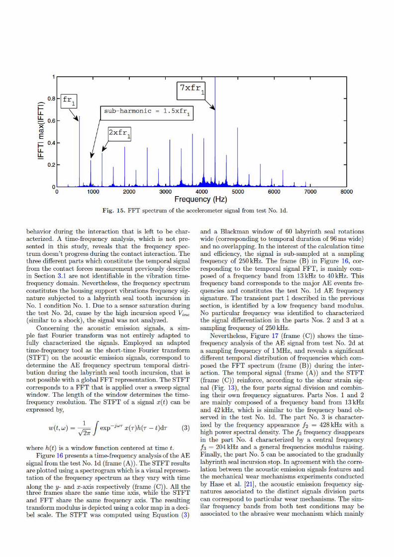
Test Nos. ld and 2d represent the overall incursion depth evolution during the interaction (from O to 265 µ,m for the test series No. 1 and from O to 229 µ,m for the test series No. 2). Figure 15 shows the accelerometer
signal fast Fourier transform (FFT) fitted on the housing support during the interaction. The rotational frequency f r1 is identified on the frequency spectrum at 625 Hz, as well as its corresponding harmonics and subharmonics. A higher vibration activity is identified around 7 x f r1. The f r1 harmonics excitement are to be expected, but it demonstrates that the vibration activity is mainly composed of forced vibrations induced by the labyrinth seal tooth rotation and the rotor unbalance. Nevertheless, the harmonics and especially the sub-harmonics may translate non-linear wear phenomena in the Al-Si 6%
I fr1I 7xfr
1 0.8 --t \ sub- harmonic 1.5xfr
1 LL ~0.6 X lxfr,I co E I- 0.4 LL LL
0.2
0 0 1000 2000 3000 4000 5000 6000 7000 8000
Frequency (Hz) Fig. 15. FFT spectrum of the accelerometer signal from test No. ld.
behavior during the interaction that is left to be characterized. A time-frequency analysis, which is not presented in this study, reveals that the frequency spectrum doesn't progress during the contact interaction. The three different parts which constitute the temporal signal from the contact forces measurement previously describe in Section 3.1 are not identifiable in the vibration t imefrequency domain. Nevertheless, the frequency spectrum constitutes the housing support vibrations frequency signature subjected to a labyrinth seal tooth incursion in No. 1 condition No. 1. Due to a sensor saturation during the test No. 2d, cause by the high incursion speed ½nc (similar to a shock) , the signal was not analyzed.
Concerning the acoustic emission signals, a simple fast Fourier transform was not entirely adapted to fully characterized the signals. Employed an adapted time-frequency tool as the short-t ime Fourier transform (ST FT) on the acoustic emission signals, correspond to determine the AE frequency spectrum temporal distribution during the labyrinth seal tooth incursion, that is not possible with a global FFT representation. The STFT corresponds to a FFT that is applied over a sweep signal window. The length of the window determines the timefrequency resolution. The STFT of a signal x(t) can be expressed by,
1 / . w(t,w) = v'27r exp-,wr x(T)h(T - t)dT (3)
where h(t) is a window function centered at time t . Figure 16 presents a time-frequency analysis of the AE
signal from the test No. ld (frame (A)) . T he ST FT results are plotted using a spectrogram which is a visual representation of the frequency spectrum as they vary with time a long they- and x-axis respectively (frame (C)). All the three frames share the same t ime axis, while the STFT and FFT share the same frequency axis. The resulting transform modulus is depicted using a color map in a decibel scale. T he STFT was computed using Equation (3)
and a Blackman window of 60 labyrinth seal rotations wide ( corresponding to temporal duration of 96 ms wide) and no overlapping. In the interest of the calculation time and efficiency, the signal is sub-sampled at a sampling frequency of 250 kHz. T he frame (B) in Figure 16, corresponding to the temporal signal FFT, is mainly composed of a frequency band from 13 kHz to 40 kHz. This frequency band corresponds to the major AE events frequencies and constitutes the test No. ld AE frequency signature. The t ransient part 1 described in the previous section, is identified by a low frequency band modulus. No particular frequency was identified to characterized the signal differentiation in the parts Nos. 2 and 3 at a sampling frequency of 250 kHz.
Nevertheless, Figure 17 (frame (C)) shows the timefrequency analysis of the AE signal from test No. 2d at a sampling frequency of 1 MHz, and reveals a significant different tempora l distribution of frequencies which composed the FFT spectrum (frame (B)) during the interaction. The temporal signal (frame (A)) and the STFT (frame (C)) reinforce, according to the shear strain signal (Fig. 13), the four parts signal division and combining their own frequency signatures. Parts Nos. 1 and 2 are mainly composed of a frequency band from 13 kHz and 42 kHz, which is simila r to the frequency band observed in the test No. ld. T he part No. 3 is characterized by the frequency appearance h = 428 kHz with a high power spectral density. T he /2 frequency disappears in the part No. 4 characterized by a central frequency '3 = 204 kHz and a general frequencies modulus raising. Finally, the part No. 5 can be associated to the gradually labyrinth seal incursion stop. In agreement with the correlation between the acoustic emission signals features and the mechanical wear mechanisms experiments conducted by Hase et al. [21], the acoustic emission frequency signatures associated to the distinct signals division parts can correspond to particular wear mechanisms. T he similar frequency bands from both test conditions may be associated to the abrasive wear mechanism which mainly

Fig. 16. Time-frequency analysis of the AE signal from test No. 1d: (A) AE temporal signal, (B) FFT modulus of AE signal,(C) STFT of AE signal
Fig. 17. Time-frequency signal from test No. 2d analysis: (A) AE temporal signal, (B) FFT modulus of AE signal, (C) STFTof AE signal.
3 A iGJ Cu
2 I
~ I
ro C: C) 0 'in s -1 . . . . . . . . I ro
0::: -2 . . . . . . . . I . . . . . . . I . . . .. . . . . .. .. .. . . ..
-3 0 10 20 50 60
-45
-50
10 10 -55 ,.,...._ N I
8 8 -60
~ ,._, > -65 (.) dB C: 6 6 Q) -70 :::, C'" Q) 4 · 4 -75 ...
lL -80
2· 2 -85
0 0 -90 1 0.5 0 10 20 30 40 50 60
IFFTl/max(IFFTI) Time (s)
AE temporal signal 10
~ A
I I 5 iJ?. il <ii
C C) 0 1ii ~ -5 ··· I· ro Cl: I
-10 0 O.Q1 0.02 0.05 0.06
5 e DB x 10 x 10
5 5 B
4.5 · 4.5 -40
~ 4 \ 4
[t2=428kHz I -50
~ 3.5 3.5 N N I I -60 ~ 3 b >- >-g 2.5 · g 2.5 Q) Q) -70 :::l :::, O" 2· ff O" 2 Q)
~ u::: 1.5 lt3= 204 kHz LL 1.5 -80
Frequency -90 0.5 0.5 band
0 0 -100 1 0.5 0 0.01 0.02 0.03 0.04 0.05 0.06 IFFTl/max(IFFTI) Time (s)

Fig. 18. Images of the abradable rub-grooves after test Nos. la, lb, le and 6a, 6b and 6c.
composed the test series No. 1. the particular frequency as '2 and fa may be associated to a severe wear, or a severe defect propagation in the Al-Si 6% coating.
3.3 A l-Si 6% worn surfaces characterizations
To complete the Al-Si 6% abradable coating behavior study and the interaction signals analysis, macrographic examinations has been initially performed on the contact protagonists after the tests and especially on the rub-groove left by the labyrinth seal tooth incursion on the Al-Si 6% coating surface.
Figure 18 presents six rub-grooves on two abradable samples among others and corresponding to the incursion tests Nos. la, lb, le, 2a, 2b and 2c. As described theoretically in Section 2.1, the contact angular length a: evolves gradually depending on the incursion depth but is not quantified in this study. A first assessment of the high-speed contact interaction was conducted in a previous study [20] by an analysis of test samples, visual rub-groove observations and accurate profile measurements which revealed different material deformation and wear phenomena. In this study, the wear dynamic is described by considering a third body approach defined as an integral part of the three level t ribological sub-system (triplet tribological [26]). In this approach, the first bodies are identified as the labyrinth seal tooth and the Al-Si 6% abradable coating. The third body is defined as a dynamic interface element such as detached particles, debrus ( omnipresent in the relevant contact) separating the contacting surfaces, which actes as an intermediate screen and is able to support the major part of the speed difference between the contact first bodies.
Figure 19 presents in front view the rub-grooves from test Nos. ld and 2d on the Al-Si 6% surface, focused on the half-section rub-groove and divided in four different observation sectors. The first sector corresponds to the
location where the incursion depth of the labyrinth tooth in the Al-Si 6% coating is the greatest, while the sector 4 corresponds to the lower incursion depth. From these test Nos. ld and 2d rub-grooves examinations, appears that the Al-Si 6% surface is mainly damaged by an abrasive wear mechanism encountered in both contact conditions. It is characterized by a high amount of fine powder particles ejection, in a pulverulent form and relatively not cohesive, thus providing a first type of third body. The powder located inside the housing support after tests has not been investigated in this study.
In addition, a large plastic deformation is observed and characterized by a large amount of plastically deformed coating on both sides of the rub-groove as a result of the high Al-Si 6% ductility. A specific adhering layer is identified in the rub-groove bottom (smooth and cohesive) and is defined as a second third body type generated at the labyrinth seal and Al-Si 6% coating interface. The third body generates a cohesive t ribofilm composed of detached elements from both two first bodies and give rise to a t ransfer layer. Finally, an interface becomes the third body layer composed of detached interfacial elements (first bodies elements) separating the contacting surfaces. An interface crack between the third body and the Al-Si 6% abradable coating is observed on the SEM image from test No. 2d (sector 2). It is demonstrated that the thermal and transverse cracks may impact the third body and generate a partial or a complete tribofilm detachment.
A rub-groove EDX analysis have been performed to identify the layer chemical composition. It mainly reveals the presence of aluminium and silicon (the Al-Si 6% abradable coating main additives), except for the test No. ld where the presence of chrome (the stainless steel X5CrNiCuNb 17-04 main additive) has been identify and seems to come from the labyrinth seal tooth. The labyrinth seal material t ransfer is perceptible on the test

Fig. 19. SEM images in front view of four different observation sectors of the rub-groove on the Al-Si 6% surface from testsNos. 1d and 2c.
Fig. 20. Stainless steel X5CrNiCuNb 17-04 transfer in the third body from tests Nos. 1b and 1c.
Nos. 1b and 1c in a lower amount (Fig. 20) and not in thetest No. 1a. According to the test No. 1d signal analysisin Section 3.1, the material transfer can be associated tothe signal part No. 3 defined previously, and occurs ata greater incursion depth than 160 μm. The presence ofthermal cracks on the third body surface indicates a sig-nificant rise in the temperature (more than 65% of tem-perature increase) followed by a rapid cooling.
It is therefore interesting to identify the mechanismduring contact instabilities by comparing the micro-graphic rub-grooves from different incursion stop condi-tions. Unfortunately, none of the test series No. 1 have
been stopped in a discontinuous contact condition, whichimplied to simulate the test No. 1d until a satisfactory re-sult was obtained. Figure 21 presents contact forces signalfrom additional test No. 1d2 and a comparison of rub-groove morphologies from test No. 1b (continuous con-tact), test No. 1c (continuous contact close to the contactinstability) and test No. 1d2 (contact instability). Fur-ther to rub-groove morphology of test No. 1d2, no ad-hering layer is observed on the rub-groove which high-lights a third body shearing on the whole rub-groove,thereby leaving a deeper rub-groove made of raw Al-Si6%. The final rub-groove statement from the test series
Rub-groove half-section
Smooth adhering layer
Test n° le
I NI I AHI\I S :l SI M 1fdlkV X11ll \1\11) 144111111 1()(lJttt1 I NI IAHBf S :l SIM 1~)111..V X1011 \'¥1) 19/111111 10011m

ao~----------- lnteractiontime(54 s) --~-----~-~ --~
Test n°1d2
z
70
60
50
~ 40 ,,, Q) u 30 0
LL 20
10
Contact loss at the end of the incursion
I -l00'------1-'--0-----20-'-------3..1.0 _____ ...1.40 _____ _,50 _____ ....,60
Time (s)
Test n° lb Test n° le Test n° 1d2
Adhering3'd body
:.'' < ,.
'.,,,,. ,i
4V
--
Adhering3rd
body
-_, .... , ... ---1st body without3rd
body
SEI 15.0kV X100 WDM.•1mm 100i,m Sf I 1~0kV X 100 Wf) l<J.?mm 1001•11 SI I 1~.mv wn 9.0mm 100,,m
F ig. 21. Contact forces signals from test No. ld2 (Vr = 37 500 rpm, Vine = 9.41 mm.s-1, Dr, = 265 µm) and comparison of the
rub-groove morphologies from tests Nos. lb, le and ld2.
No. 1, depending on the incursion depth, depends on the incursion stop contact conditions and more globally of the third body life during the high speed contact interaction.
To complete the rub-grooves front view observations on the Al-Si 6% surface, microscopic examinations on cross-section views of the rub-grooves were performed on the Al-Si 6% abradable surface at the maximum incursion depth a rea. For that, the half section rub-groove in Figure 19 was cut up, embedded in a phenolic resin and polished using a 3 µ,m diamond suspension.
Figure 22 presents a cross-section views of the
rub-groove morphology from test No. l e (Vr 37 500 rpm, ½nc = 0.005mm.s-\ Dp = 215µ,m) and highlights the third body distribution around the rub-groove. Various third body thicknesses (thicker at the tooth center) reveal the existence of a material confinement phenomena, induced by the contact pressure caused by the labyrinth seal incursion. In addition, the second third body type ejection is identified as a deformation mechanism on both sides of the rub-groove at the origin of the amount of plastically deformed material ejected from the contact on the Al-Si 6% surface.
Additional microscopic examinations on cross-section views of the labyrinth seal tooth after test were performed on the unique labyrinth seal sample used on this study in order to superimpose the labyrinth seal tooth inside the rub-groove and highlight the contact evolution.
Figure 23 presents successive cross-section views of the labyrinth seal tooth inside the rub-groove at the maximal incursion depth from tests Nos. la, lb, le and l d (Vr = 37 500 rpm, ½nc = 0.005 mm.s- 1) and tests Nos. 2a, 2b, 2c and 2d (Vr = 5 000 rpm, ½nc = 9.41 mm.s-1) in respect of increasing incursion depths. T his evolution quantitatively reflects that the Al-Si 6% wear and particularly the incursion depth Dp into Al-Si 6% can be qualified as imposed by the labyrinth seal tooth. In fact , the rubgroove geometry on the Al-Si 6% abradable coating are very similar to the labyrinth seal tooth geometry, regardless the interaction test conditions. The Al-Si 6% behavior differences are then focused on the third body nature and its evolution, resulting of the interaction. It has been previously indicated, that the rub-groove surface roughness or chemical composition depends on the full life-cycle of the third body. Figure 24 presents the tribofilm thickness

Fig. 22. Rub-groove morphology on a cross-section view focused on the third body distribution (SEM images from test No. 1c(Vr = 37 500 rpm, Vinc = 0.005 mm.s−1, Dp = 215 μm).
Fig. 23. SEM image on cross-section views of the labyrinth seal tooth inside the rub-grooves.
evolution as a function of the test series conditions andthe incursion depth Dp and highlights that such thicknessdepends on the incursion depth. It is indeed necessary toestimate the full-life contact scenario by considering therole of the both first bodies and third body according tothe creation of debris, the material flow direction, and theejection out of the friction rub-grooves.
The role of the contact confinement and the possibil-ity of a chemical reaction with the oxygen may explainthese two kind of particles production. In this approach,the tribological cycle deals with the different material flowcreate during the contact: two distinct material flows op-erate in this case are identified:
– a very majority longitudinal flow (in the direction ofthe labyrinth seal tooth rotation) and characterizedby a low third body confinement referred to as a high
speed ejection out of the contact. This longitudinalflow is generated by the abrasion wear mechanism.
– a minority transverse flow (perpendicular to the rub-groove direction) characterized by a high material con-finement and controlled by the incursion depth of thetooth. It is generated by an adhesive wear mechanismwithout support of oxygen. The ejection of this ad-hering and ductile layer is observed by a large amountof plastically deformed material on both sides of therub-groove as a result of free-surface creation at thetooth end.
4 Conclusions
In this study, the high speed interactions between anAl-Si 6% abradable coating and a stainless steel labyrinth
-e,ln"lb _ _ •~ Tesln'lc •• Te,tn"ld . ~~- co • • J. .. •
,-., - · __ -· :--~, ;r' :- ----- :_ I ;;_ ·-.,.,. ~ \... j •• '
~
-. •, Q • . _ ,., ------------------------···· ··········· ·············-·
-f : I'. ; :,~··.. ·~•~ ·, , , ··,r,~ nn· ,,., 1'..fb .. ,m,.,. •
1
• Testn'2a ••• ·- • _ lost_,.,!,··-- _ . . -esto'2c • - • _ ' ic•s. n"l tl 1~,. •·-
: • ·. ~ . - • ,I, : .. -·. • • , .. .. -
,-"' . . ,: :::. ;~. ;~~- . ~---, - - - -"' ~ ' , . ( - • . : j" • 4 ~ '
",-

Fig. 24. Maximal adhering layer thickness depending on the incursion depth Dp and the test series conditions.
seal tooth were performed using a high-speed test rigin order to improve a better understanding of the Al-Si6% behavior under severe labyrinth/coating high speedcontact. The Al-Si 6% tribological behavior was stud-ied and simulated following two severe tribological con-ditions. The first severe wear conditions is characterizedby a high number of labyrinth seal revolutions and anassociated rubbed length for the first one, whereas thesecond severe rubbing condition is described with a highfeed-rate leading to a high abradable material flow. Addi-tional experimental interaction data are provided by de-veloping a special instrumentation composed of contactforces, accelerometers, thermocouples, contact conditionand acoustic emissions sensors, able to simultaneouslyrecord with different synchronized signals of sampling fre-quency coming from the incursion tests. Successive in-cursion depths, separated from each other by a distanceof 50 μm have been simulated to perform allowing visualpost-tests worn material examinations depending on theinteraction time. The results showed that:
– The Al-Si 6% behavior (subjected to the first tribo-logical condition) is mainly characterized by a discon-tinuous abrasion wear mechanism composed of succes-sive and periodic Al-Si 6% wrenching. In addition tothe contact surfaces impact during the interaction, asignificant Al-Si 6% behavior change is observed overa certain incursion depth, and enables the labyrinthseal tooth material transfer inside the Al-Si 6% coat-ing. The occurrence of an adhesive wear mechanismcan explain the combined increase of friction coeffi-cient and temperature.
– Concerning the second tribological condition, theAl-Si 6% coating is subjected to similar wear mecha-nisms. The Al-Si 6% behavior is significantly affectedafter two labyrinth seal rotations with an increase ofthe friction coefficient. The different frequency sig-natures (corresponding to one labyrinth seal rota-tion) are highlighted using the time-frequency analy-
sis of the acoustic emission signals. According to manystudy available on the literature, these frequency sig-natures may be associated to different wear mecha-nisms which defined the Al-Si 6% abradable coatingbehavior.
The wear dynamic have been better studied by consider-ing a third body approach on both test conditions. Thefirst body (the Al-Si 6% coating) is mainly damaged anddeformed, forming rub-grooves with different characteris-tics. The second first body (the labyrinth seal tooth) ispractically not deformed and weared. Two different vari-eties of particles production have been identified; a duc-tile and an adhering layer on the rub-groove bottom andpulverulent fine powder particles, relatively not cohesive(probably as oxide) thus providing two different kind ofthird body. The particles detachment from Al-Si 6% andlabyrinth seal tooth (first bodies) generates the sourceflow thus creating the adhering layer. It is mainly com-posed of aluminium and silicon (second test conditions)but also of a blend of labyrinth seal tooth materiel trans-ferred (first test conditions).
Finally, it has been demonstrated that the evolutionof the third body and his life cycle during the contacthave a major impact on the final rub-groove morphology.This study should be complemented by precisely evaluat-ing particles ejected during the interaction (size, chemicalcomposition), effects of the labyrinth seal rotation and in-cursion on both material flows to established the life of thecontact according to the overall interaction parameters.
Acknowledgements. These investigations were supported bythe European Commission through the FP7 E-BREAKproject under Grant Agreement No. 314366 and by SAFRAN-TURBOMECA. The study also received financial support ofthe Agence Nationale de la Recherche et de la Technologie(ANRT). The support of these organisation is gratefully ac-knowledged.
_ 60
E :. so -"' "' ~ 4 0
C .:.:: 30 IJ :c 20 .. .. ~ 10 > .!! IJ 0 ; -~ ~ a. V, 162,S
Incursion depth "Op" (µm) • Test n°1(Vr=37500 rpm, Vinc=0.005 mm.s-1) • Test n° 2 (Vr=S 000 rpm, Vinc=9.41 mm.s-1)
267,7

References
[1] M. Dorfman, U. Erning, J. Mallon, Gas turbines useabradable coatings for clearance-control seals, Seal.Technol. 97 (2002) 7–8
[2] W. Dalzell, S. Sanders, G. Crawford, F. Walden,W. Woodard, Abradable seal having improved proper-ties, US Patent No. 6 352 264, 2002
[3] G. Jacquet-Richardet, M. Torkhani, P. Cartraud,F. Thouverez, T. N. Baranger, M. Herran, C. Gibert,S. Baguet, P. Almeida, L. Peletan, Rotor to stator con-tacts in turbomachines. review and application, Mech.Syst. Signal Process. 40 (2013) 401–420
[4] R. Schmid, F. Ghasripoor, M. Dorfman, X. Wie,An overview of compressor abradable thermal sprays,in: Surface Engineering International Thermal SprayConference ITSC, 2000, pp. 406–412
[5] P. Dowson, M. Walker, A. Watson, Development ofabradable and rub-tolerant seal materials for applica-tion in centrifugal compressors and steam turbines, Seal.Technol. 12 (2004) 5–10
[6] Y. Maozhong, H. Baiyun, H. Jiawen, Erosion wear be-haviour and model of abradable seal coating, Wear 252(2002) 9–15
[7] M. Cuny, Contribution to the local characterization ofpairs of materials involved during rotor/stator contactin a turbomachine, Ph.D. thesis, Universite de Lorraine,2012
[8] S. Baız, Experimental study of blade/abradable contact:contribution to the mechanical characterization of abrad-able materials and their dynamic interaction on rotatingtest bench with a rotating test rig with a blade, Ph.D.thesis, Ecole centrale de Lille, 2011
[9] M. Proctor, J. Delgado, Leakage and power loss test re-sults for competing turbine engine seals, in: ASME TurboExpo 2004: Power for Land, Sea, and Air, 2004, pp. 441–451
[10] I. Delgado, M. Proctor, Continued investigation of leak-age and power loss test results for competing turbine en-gine seals, Tech. rep., NASA/TM-2006-214420 (2006)
[11] D. Collins, J. Teixeira, P. Crudgington, The degradationof abradable honeycomb labyrinth seal performance dueto wear, Seal. Technol. 8 (2008) 7–10
[12] D. Rhode, R. Hibbs, Clearance effects on correspondingannular and labyrinth seal flow leakage characteristics, J.Tribol. 115 (1993) 699–704
[13] A. Gamal, J. Vance, Labyrinth seal leakage test: toothprofile, tooth thickness, and eccentricity effects, ASMEJ. Eng. Gas Turbines Power 130 (2008) 11
[14] L. Dobek, Labyrinth seal testing for lift fan engines, Tech.rep., Pratt and Whitney Aircraft Division United AircraftCorporation, 1973
[15] J. Denecke, V. Schramm, S. Kim, S. Wittig, Influence ofrub-grooves on labyrinth seal leakage, in: ASME TurboExpo 2002: Power for Land, Sea, and Air, AmericanSociety of Mechanical Engineers, 2002, pp. 771–779
[16] P. Dowson, S. Ross, C. Schuster, The investigation of suit-ability of abradable seal materials for application in cen-trifugal compressors and steam turbines, in: Proceedingsof the twentieth turbomachinery symposium, 1991
[17] J. Whalen, E. Alvarez, L. Palliser, Thermoplasticlabyrinth seals for centrifugal compressors, in: Proceedingof the thirty third Turbo Symposium, 2004
[18] Z. Mutasim, L. Hsu, E. Wong, Evaluation of plasmasprayed abradable coatings, Surf. Coat. Technol. 54(1992) 39–44
[19] S. Wilson, Ensuring tight seals, Tech. rep., SulzerTechnical Review 2, 2007
[20] C. Delebarre, V. Wagner, J. Paris, G. Dessein, J. Denape,J. Gurt-Santanach, An experimental study of the highspeed interaction between a labyrinth seal and an abrad-able coating in a turbo-engine application, Wear 316(2014) 109–118
[21] A. Hase, H. Mishina, M. Wada, Correlation between fea-tures of acoustic emission signals and mechanical wearmechanisms, Wear 292-293 (2012) 144–150
[22] L. Marinescu, D. Axinte, A time frequency acousticemission-based monitoring technique to identify work-piece surface malfunctions in milling with multiple teethcutting simultaneously, Int. J. Machine Tools Manuf. 49(2009) 53–65
[23] M. Noone, R. Mehan, Observation of crack propagationin polycrystalline ceramics and its relationship to acous-tic emissions, in: Concepts, Flaws, and Fractography,Springer, US, 1974, Vol. 1, pp. 201–229
[24] A. Prillieux, L. Talotte, Determining the evolution of themechanical properties of alsi and abradable almn alu-minum base., Tech. rep., Institut Carnot Cirimat, 2013
[25] G. Chen, Z. Zhou, Time-frequency analysis of friction-induced vibration under reciprocating sliding conditions,Wear 262 (2007) 1–10
[26] Y. Berthier, P. Kapsa, L. Vincent, Material and contacts:A tribological approach, 1998