Labyrinth:+Awakening+Event+ Card+Background+...Labyrinth Awakening ...
Upload
surawutwijarnCategory
view
112download
18description

Advanced Steam Labyrinth Seal Design
Phase 1 Initial Concept Evaluation
Technical Report
LI
CE
NS E D
M A T E
RI
AL WARNING:
Please read the Export ControlAgreement on the back cover.


EPRI Project Manager S. Hesler
Electric Power Research Institute • 3412 Hillview Avenue, Palo Alto, California 94304 • PO Box 10412, Palo Alto, California 94303 • USA 800.313.3774 • 650.855.2121 • [email protected] • www.epri.com
Advanced Steam Labyrinth Seal Design Phase 1 Initial Concept Evaluation 1011932
Final Report, May 2005

DISCLAIMER OF WARRANTIES AND LIMITATION OF LIABILITIES
THIS DOCUMENT WAS PREPARED BY THE ORGANIZATION(S) NAMED BELOW AS AN ACCOUNT OF WORK SPONSORED OR COSPONSORED BY THE ELECTRIC POWER RESEARCH INSTITUTE, INC. (EPRI). NEITHER EPRI, ANY MEMBER OF EPRI, ANY COSPONSOR, THE ORGANIZATION(S) BELOW, NOR ANY PERSON ACTING ON BEHALF OF ANY OF THEM:
(A) MAKES ANY WARRANTY OR REPRESENTATION WHATSOEVER, EXPRESS OR IMPLIED, (I) WITH RESPECT TO THE USE OF ANY INFORMATION, APPARATUS, METHOD, PROCESS, OR SIMILAR ITEM DISCLOSED IN THIS DOCUMENT, INCLUDING MERCHANTABILITY AND FITNESS FOR A PARTICULAR PURPOSE, OR (II) THAT SUCH USE DOES NOT INFRINGE ON OR INTERFERE WITH PRIVATELY OWNED RIGHTS, INCLUDING ANY PARTY'S INTELLECTUAL PROPERTY, OR (III) THAT THIS DOCUMENT IS SUITABLE TO ANY PARTICULAR USER'S CIRCUMSTANCE; OR
(B) ASSUMES RESPONSIBILITY FOR ANY DAMAGES OR OTHER LIABILITY WHATSOEVER (INCLUDING ANY CONSEQUENTIAL DAMAGES, EVEN IF EPRI OR ANY EPRI REPRESENTATIVE HAS BEEN ADVISED OF THE POSSIBILITY OF SUCH DAMAGES) RESULTING FROM YOUR SELECTION OR USE OF THIS DOCUMENT OR ANY INFORMATION, APPARATUS, METHOD, PROCESS, OR SIMILAR ITEM DISCLOSED IN THIS DOCUMENT.
ORGANIZATION(S) THAT PREPARED THIS DOCUMENT
The University of Tennessee Space Institute
ORDERING INFORMATION
Requests for copies of this report should be directed to EPRI Orders and Conferences, 1355 Willow Way, Suite 278, Concord, CA 94520, (800) 313-3774, press 2 or internally x5379, (925) 609-9169, (925) 609-1310 (fax).
Electric Power Research Institute and EPRI are registered service marks of the Electric Power Research Institute, Inc.
Copyright © 2005 Electric Power Research Institute, Inc. All rights reserved.

CITATIONS
This report was prepared by
The University of Tennessee Space Institute 411 B.H. Goethert Parkway Tullahoma, TN 37388
Principal Investigator A. Vakili
This report describes research sponsored by the Electric Power Research Institute (EPRI).
The report is a corporate document that should be cited in the literature in the following manner:
Advanced Steam Seal Labyrinth Design: Phase 1 Initial Concept Evaluation. EPRI, Palo Alto, CA: 2005. 1011932.
iii


PRODUCT DESCRIPTION
This report evaluates the design advantages of a number of new labyrinth seal concepts compared to an existing seal for specific locations along steam turbine shafts (such as the N2 packing on a combined high pressure–intermediate pressure [HP-IP] shaft). The physics of fluid flow in selected new labyrinth seals along with the flow pattern and its effect on the dynamics of the turbine shaft have been examined, and the results are presented in this report. The new seals have specific features that are designed to minimize two basic and critical seal design performance issues: leakage through the seals and shaft dynamics effects on the leakage. In recent years, interest in increased efficiency of various turbines, including steam power-generating turbines, has grown. As the unit price of energy increases, efficiency of the production and consumption units becomes more relevant to the producers and to the consumers. Seals are one of the key components for improving the efficiency of steam turbines. Improving the seal is accomplished through better leakage reduction that will reduce wasted steam, improving the efficiency of the turbines. In addition to reduced leakage, today’s power producers demand reliability and seek a reduction in unscheduled maintenance caused by seal damage.
Results and Findings A new labyrinth seal has been conceptually developed that has a number of advantages and allows some flexibility in the implementation of the seal at various stages of axial-flow machines. The new seal also has the potential for reducing leakage and improving rotor dynamic stability. Durability of the design is a key requirement that will be addressed in a subsequent phase of research. Leakage flow results obtained to date are based on numerical simulation and would need to be validated through physical experimentations. This numerical investigation is justified primarily as an initial effort due to the simplicity of the new seal and its future potential. The seal cross-section is curved, and—if constructed from a material that allows elastic deformation—it would be compliant if rubbed by the turbine shaft. In this manner, the seal clearance with respect to the shaft could initially be small. During operation, as the shaft-seal clearance is decreased, the local pressure would increase and have a stabilizing effect on the shaft dynamics.
Challenges and Objectives This report is useful for the power generation technology and plant managers, engineers, designers, and maintenance supervisors associated with the operation of steam turbines. The report describes a number of innovative axial-flow labyrinth seal designs. Two-dimensional axisymmetric flow analyses were performed to optimize leakage reduction with these seal design concepts. Additional studies are recommended, and those with current seal design or operational concerns may be particularly interested in reading about, following, and supporting this effort.
v

Applications, Value, and Use The types of seals examined in this report can potentially reduce steam leakage or operate at increased nominal clearance so that rubs are less likely to occur during startups. In addition, there is potential for improved shaft stability with these labyrinth concepts. The potential applications would then be for all seals, where long-term durability and improved performance are desirable.
EPRI Perspective Steam turbines in many of today’s generating stations use interstage labyrinth designs that are essentially unchanged from those employed more than 30 years ago. Despite the significant numerical analysis capabilities offered by computational fluid dynamics (CFD), few improvements have been made in the basic axial flow labyrinth seal design. Parametric analyses such as those presented in this report can be used to design improved retrofit seals that are economical, improve operating efficiency, and extend the time between turbine overhauls.
Approach This report contains the results of an initial study in which two-dimensional and axisymmetric CFD was used to optimize the geometric characteristics of a new labyrinth seal design concept based on the criteria of reduced leakage.
Keywords Steam turbine Seals Labyrinth Steam leakage Packing
vi
EPRI Proprietary Licensed Material
ACKNOWLEDGMENTS
EPRI and The University of Tennessee Space Institute (UTSI) would like to acknowledge Lew Shuster of Reliant Resources for his role in initiating this research and his advice in developing the work scope and recommendations.
UTSI graduate students who have contributed to this study are Sricharan Ayyalasomayajula and Abraham J. Meganathan. Their participation in this study and assistance in performing the details of this research are gratefully acknowledged.
vii


EPRI Proprietary Licensed Material
ABSTRACT
A number of new labyrinth seal concepts and their design advantages over an existing seal have been comparatively evaluated. The leakage flow in a number of new and in one traditional stationary stepped labyrinth seal was investigated using computations (two-dimensional [2-D] and axisymmetric computational fluid dynamics [CFD] modeling) of the flow through the seal. The recommended optimized seal cross-section is curved with a compliant profile that allows elastic deformation of the seal if rubbed because of the dynamics of the turbine shaft.
Design features for the new seals considered in this report are based on physical principles. First, the smaller the clearance gaps between the shaft and the seal, the lower the steam leakage through the seal. Second, conformal flexibility of a seal is highly desirable (if it can be achieved) in a seal’s performing better than traditional fixed-shape radial-profile seals. The challenge is to design a seal with the given geometry from a material that would accommodate the amount of deflection needed without exceeding the elastic structural limits of the material.
Therefore, the seals considered in this study have curved (that is, flexible) profiles that allow the individual seals to deflect with the shaft at any time, not just during the startup process. This profile has been named the “C” seal for the purposes of this report. This feature is conjectured to have a special effect that is favorable to the shaft dynamics. The C seal clearance with the shaft could initially be even smaller than that with baseline seals because it has intrinsic flexibility and would not damage the shaft during its excursions. During operations such as startup, as the shaft’s relative distance to the seal is decreased and contact is made, a large arc of the C seal comes in contact with the shaft because of its flexibility. Therefore, the local pressure increases, creating a stabilizing effect on the shaft. This allows for smaller clearance gaps to be maintained even after a rub.
The material and structural aspects of the design issues are not addressed in this Phase 1 effort because of the limitations in scope and computational capacity. Flow through the seals, as computed from the CFD models, showed significant leakage reduction as compared to baseline seals. It is conjectured that this leakage level would generally remain constant below the baseline levels throughout the life of the seal if the design features relating to labyrinth compliance are accomplished.
ix


EPRI Proprietary Licensed Material
CONTENTS
1 INTRODUCTION ....................................................................................................................1-1 Nomenclature........................................................................................................................1-2
2 TECHNICAL DISCUSSIONS .................................................................................................2-1 Seal Discharge Coefficient ....................................................................................................2-3 Flow Parameter .....................................................................................................................2-4 Total Pressure Loss ..............................................................................................................2-4
3 PRESENT STUDY..................................................................................................................3-1 Baseline ................................................................................................................................3-1 New Seal Designs.................................................................................................................3-2 Numerical Modeling Setup ....................................................................................................3-5
4 RESULTS ...............................................................................................................................4-1 Validation of CFD Analysis....................................................................................................4-1 Analysis of the Baseline Seal Flow .......................................................................................4-1 Performance of New Seals....................................................................................................4-4 Structural Analysis...............................................................................................................4-12
5 CONCLUSIONS .....................................................................................................................5-1 Recommendations ................................................................................................................5-2
6 REFERENCES .......................................................................................................................6-1
A SUMMARY OF CALCULATED LEAKAGE FLOWS FOR VARIOUS LABYRINTH CONFIGURATIONS ................................................................................................................. A-1
xi


EPRI Proprietary Licensed Material
LIST OF FIGURES
Figure 2-1 Schematic Representation of a Generic Stepped Labyrinth Seal, Depicting Two Cycles of a Seal (each cycle is composed of three stages; pressure in the ith stage is designated as Pi) ..................................................................................................2-2
Figure 2-2 Schematic Representation of a Generic Straight-Through Labyrinth Seal, Depicting Two Cycles of a Seal (each cycle is composed of three stages; pressure in the ith stage is designated as Pi) .....................................................................................2-2
Figure 3-1 Baseline Stepped Labyrinth Seal Geometry Used for Numerical Modeling Showing Boundary Conditions and the Grid (x/L = 0.043; see Figure 2-1)........................3-1
Figure 3-2 C-Shaped Tall Knife (Sharp-Edged) and Two Vertical Short Knives........................3-2 Figure 3-3 Z-Shaped Knives, One Tall and Two Short Knives ..................................................3-2 Figure 3-4 C-Shaped Sharp-Edged Knives, One Tall and Two Short Knives (C Sharp +
CC).....................................................................................................................................3-2 Figure 3-5 C-Shaped Sharp-Edged Knives, One Tall and Three Short Knives (C Sharp +
CCC) ..................................................................................................................................3-3 Figure 3-6 C-Shaped Flat-Edged Knives, One Tall and Two Short Knives (C Flat + CC) .........3-3 Figure 3-7 C-Shaped Flat-Edged Knives, One Tall and Three Short Knives (C Flat +
CCC) ..................................................................................................................................3-3 Figure 3-8 Baseline Seal with Bent Knives, Resulting in Increased Clearance .........................3-4 Figure 3-9 C-Shaped Flat (One Tall and Two Short) C-Knives – Bent (increased
clearance as in Figure 3-8) ................................................................................................3-4 Figure 3-10 C-Shaped Flat (One Tall and Three Short) Knives – Bent (increased
clearance as in Figure 3-8) ................................................................................................3-4 Figure 4-1 Comparisons of Computational and Experimental Results ......................................4-2 Figure 4-2 Variation of Predicted Total Pressure Across the Multistage Baseline Seal
Assembly............................................................................................................................4-2 Figure 4-3 Velocity Vectors from CFD Analysis on the Baseline Seal .......................................4-3 Figure 4-4 Percent Change in Leakage of New Labyrinth Designs Compared to an
Undamaged Vertical Knife Configuration as Shown in Figure 2-1 .....................................4-6 Figure 4-5 Percent Change in Leakage of Undamaged Curved Seal Configurations
Relative to a Damaged Vertical Knife Configuration ..........................................................4-7 Figure 4-6 Stream Function Contour Plot of Baseline Seal (P1/P14 = 10) ................................4-8 Figure 4-7 Stream Function Contour Plot of C-Shaped Tall Knife and Vertical Short
Knives (P1/P14 = 10) ........................................................................................................4-8 Figure 4-8 Stream Function Contour Plot of Z-Shaped Tall and Short Knives (P1/P14 =
10) ......................................................................................................................................4-8
xiii
EPRI Proprietary Licensed Material
Figure 4-9 Stream Function Contour Plot of C-Shaped One Tall and Two Short Sharp Knives (P1/P14 = 10) ........................................................................................................4-9
Figure 4-10 Stream Function Contour Plot of C-Shaped One Tall and Three Short Sharp Knives (P1/P14 = 10) ........................................................................................................4-9
Figure 4-11 Stream Function Contour Plot of C-Shaped One Tall and Two Short Flat Knives (P1/P14 = 10) ........................................................................................................4-9
Figure 4-12 Stream Function Contour Plot of C-Shaped One Tall and Three Short Flat Knives (P1/P14 = 10) ........................................................................................................4-9
Figure 4-13 Stream Function Contour Plot of Deformed Vertical Knife (P1/P14 = 10) ............4-10 Figure 4-14 Stream Function Contour Plot of Deformed C-Shaped One Tall and Two
Short Flat Knives (P1/P14 = 10).......................................................................................4-10 Figure 4-15 Stream Function Contour Plot of Deformed C-Shaped One Tall and Three
Short Flat Knives (P1/P14 = 10).......................................................................................4-10 Figure 4-16 Velocity Vectors for the New Seal Designs (Pressure Ratio = 10) .......................4-11 Figure 4-17 Vertical Seal – Deformation in the X Direction for an Imposed 1.02-mm Tip
Deflection .........................................................................................................................4-13 Figure 4-18 Vertical Seal – Deformation in the Y Direction for an Imposed 1.02-mm Tip
Deflection .........................................................................................................................4-13 Figure 4-19 Vertical Seal – Stress in the X Direction for an Imposed 1.02-mm Tip
Deflection .........................................................................................................................4-14 Figure 4-20 Vertical Seal – Stress in the Y Direction for an Imposed 1.02-mm Tip
Deflection .........................................................................................................................4-14 Figure 4-21 C-Shaped Sharp Tip Seal – Deformation in the X Direction for an Imposed
1.02-mm Tip Deflection ....................................................................................................4-15 Figure 4-22 C-Shaped Sharp Tip Seal – Deformation in the Y Direction for an Imposed
1.02-mm Tip Deflection ....................................................................................................4-15 Figure 4-23 C-Shaped Sharp Tip Seal – Stress in the X Direction for an Imposed 1.02-
mm Tip Deflection ............................................................................................................4-16 Figure 4-24 C-Shaped Sharp Tip Seal – Stress in the Y Direction for an Imposed 1.02-
mm Tip Deflection ............................................................................................................4-16 Figure 4-25 C-Shaped Flat Tip Seal – Deformation in the X Direction for an Imposed
1.02-mm Tip Deflection ....................................................................................................4-17 Figure 4-26 C-Shaped Flat Tip Seal – Deformation in the Y Direction for an Imposed
1.02-mm Tip Deflection ....................................................................................................4-17 Figure 4-27 C-Shaped Flat Tip Seal – Stress in the X Direction for an Imposed 1.02-mm
Tip Deflection ...................................................................................................................4-18 Figure 4-28 C-Shaped Flat Tip Seal – Stress in the Y Direction for an Imposed 1.02-mm
Tip Deflection ...................................................................................................................4-18
xiv

EPRI Proprietary Licensed Material
LIST OF TABLES
Table 4-1 Comparison of Computational and Experimental Results ........................................4-1 Table A-1 Nominal Leakage Flow (kg/s) Based on Two-Dimensional CFD Calculation
for Seal Geometries Identified in Section 3....................................................................... A-2 Table A-2 Percent Change in Calculated Leakage Flow Relative to Baseline Vertical
Knife Design* .................................................................................................................... A-2 Table A-3 Nominal Leakage Flow (kg/s) Based on Two-Dimensional CFD Calculation of
Damaged Seal Configurations .......................................................................................... A-3 Table A-4 Percent Change in Calculated Leakage Flow Relative to Vertical Knife
Design*.............................................................................................................................. A-3
xv


EPRI Proprietary Licensed Material
1 INTRODUCTION
The efficiency of modern steam turbines has long been dependent on a number of factors. Minimizing leakage of steam that bypasses the fixed and rotating blade elements and passes through the shaft end packing is critical in modern machines. Maintaining low leakage rates requires improved packing designs. One traditional type of interstage packing uses labyrinth seals—a noncontacting type of seal that is designed to produce a significant pressure drop in the leakage steam. These seals have been in use for decades in a variety of turbo-machinery applications [1–4].
The problem of leakage between the different pressure zones, or stages, directly affects the amount of steam flow performing useful work and thus the amount of power delivered by the turbine. An attractive feature of labyrinth seals is that they do not contact the rotating shaft. This has a direct impact on the integrity of the rotor and also drastically decreases the cost of regular replacement and maintenance compared to other contacting seals, such as brush seals. Recently, brush seals have received special attention because they can be quite effective in reducing steam leakage [5]. However, these seals do have certain shortcomings. Brush seals work well in reducing leakage if their clearance relative to the shaft is small. They are most effective as contact seals, for which life and wear rate are major concerns. At certain locations along the shaft, the lateral displacement of the shaft at critical speed during startup exceeds the brush seal’s limit, and the seal and shaft wear is quite high. For such situations, if the initial clearances for the seals are too small, the seal and the shaft may be damaged. The seal clearances after such a rub event are large, which reduces the seal’s performance. In addition, bristle loss and debris could lead to maintenance problems.
A number of alternative interstage packing designs are available, such as retractable and brush seals. A configuration incorporating the use of both labyrinth and brush seals has also been studied [6]. Advantages derived from the lowered maintenance and replacement costs in the long run have led to renewed efforts in enhancing the performance of the labyrinth seal. The key design factor restricting leakage is the large total pressure drop produced by flow passing through multiple labyrinth seals. If not damaged, multiple labyrinth seals are capable of dropping the leakage stream pressure to a level near that of the exhaust pressure, thus reducing the leakage flow.
1-1

EPRI Proprietary Licensed Material Introduction
The present study has been mainly concentrated on the conceptual development of new configurations of labyrinth seals. The main objective of this study has been to develop a new design for the labyrinth seal using numerical modeling, with the following advantages:
• Good dynamic sealing properties
• Higher mechanical strength
• Simple geometry for ease of manufacture and maintenance
Nomenclature
Acl seal clearance area
Cd seal discharge coefficient
cl seal clearance height
Chl chamber length
Chh chamber height
Φ flow parameter
Ψ stream function
k specific heat ratio
L step width
m& mass flow rate
Pi static pressure at ith chamber
Pt stagnation pressure
PR pressure ratio
θ knife angle
Sh step height
T temperature
x axial position of knife with respect to step
1-2
EPRI Proprietary Licensed Material
Introduction
K degrees Kelvin temperature
k-ε Turbulent Kinetic Energy model used in CFD
y+ nondimensional wall layer dimension
yP distance from point P to wall
ρw fluid density at the wall
µ fluid viscosity
τw wall shear stress
HP high pressure
IP intermediate pressure
2-D two-dimensional
CFD computational fluid dynamics
FLUENT commercial software for performing computational fluid dynamics
PIV particle image velocimetry
N2 designation of packing between HP and IP sections of a combined HP-IP turbine rotor
kg kilograms
s seconds
sec seconds
1-3


EPRI Proprietary Licensed Material
2 TECHNICAL DISCUSSIONS
An inherent design problem in turbo-machinery is minimizing leakage between stages and through shaft end packings. This issue has assumed greater importance as typical operating pressures have increased over the years. The labyrinth seal is a noncontacting shaft seal that has been in widespread use for many decades in a variety of applications [1–4]. Labyrinth seals are typically used as a shaft seal in steam and gas turbines, compressors, turbo-chargers, and various other applications where a robust yet relatively simple, passive seal is required between two zones with significantly different pressures. Labyrinth seals have numerous intrinsic benefits including low maintenance, negligible running torque, simplicity, and reduced particulate contamination. However, typical labyrinth seals have an innate tendency to leak because there is no mechanical seal between the two areas of differing pressures. Although other types of contacting seals have been devised that provide better leakage characteristics, the reliance on contact between a rotating and nonrotating surface with these devices leads to unacceptable levels of wear. Other seal types include the viscoseal [7] (for relatively high viscous fluids) and the brush seal [5] (limited by material properties).
The leakage flow through a labyrinth seal can be considered as a flow through a series of orifice restrictions. Figure 2-1 depicts a schematic representation of a labyrinth seal with vertical knives and steps, including the definition of key parameters. In a global sense, losses caused by individual restrictions and obstacles combine to produce a net energy loss to the system. The fluid, driven by the total pressure differential between Pi and Pi+1 (as shown in Figure 2-1) is forced through a narrow clearance (restriction). As the fluid passes through the restriction (acting as an orifice), it undergoes an increase in velocity and a corresponding decrease in pressure with increased turbulence due to the sharp knife tip. At some point after the orifice, the fluid adjusts to the pressure condition in the next chamber. During this process, some of the kinetic energy of the fluid is recovered as a pressure rise, and some losses are converted to heat. The remaining total pressure of the fluid provides the pressure difference that forces the fluid to enter the next stage of the seal. Ideally, the kinetic energy of the fluid resulting from the previous stage of throttling will be dissipated before the fluid enters the next stage [8, 9]. In this manner, by the time the fluid has traveled through all of the stages of the seal, its total pressure difference is greatly reduced, leading to negligible leakage flow through the seal.
2-1

EPRI Proprietary Licensed Material Technical Discussions
Figure 2-1 Schematic Representation of a Generic Stepped Labyrinth Seal, Depicting Two Cycles of a Seal (each cycle is composed of three stages; pressure in the ith stage is designated as Pi)
Figure 2-2 Schematic Representation of a Generic Straight-Through Labyrinth Seal, Depicting Two Cycles of a Seal (each cycle is composed of three stages; pressure in the ith stage is designated as Pi)
In a labyrinth seal, the flow locally changes direction often and rapidly speeds up and down as it negotiates a path through the seal. Total pressure is lost continuously through the seal, but there may be local rises in static pressure due to area changes, local stagnation points, and sudden expansions as the fluid flows into a chamber of the seal.
2-2

EPRI Proprietary Licensed Material
Technical Discussions
Methods for analyses [10–15] of labyrinth seal leakage can be classified into two main categories: global models and knife-to-knife models. Knife-to-knife models explicitly characterize the system geometry and calculate the internal flow through a seal by calculating relevant physical parameters as they change at various points internal to the seal.
Although computationally intensive, this knife-to-knife method allows for changes in flow behavior at each throttling within the seal. Global models approximate the labyrinth seal either by evaluating the cumulative effect due to the series of throttling losses or as a rough pipe model with uniformly distributed wall friction.
Although either of these approaches can yield good empirical correlations, the rough pipe model provides little information to the seal designer in terms of physically relevant design parameters such as knife spacing, shape, and sequence. A series of restriction global models provides good results but encounters difficulty when calculating kinetic energy carryover. Additionally, problems are encountered predicting seal behavior in choked flow regimes [12].
With the significant advances in computational capabilities, numerical analysis of computational fluid dynamics is increasingly used to study, evaluate, and predict seal designs [16–25]. The effect of the labyrinth seal flow on rotor dynamics is also an important topic that has been studied extensively [26–32].
Based on a review of the open literature, there appears to be a deficiency in available information detailing the behavior of stepped labyrinth seals with constant rotor diameter (see Figure 2-1). Greater success has been obtained analyzing and predicting the leakage of straight-through labyrinth seals (see Figure 2-2) due to the relative simplicity of the internal flow and the wide availability of experimental results [33–35]. This report addresses the stepped labyrinth seal flow physics and relates them to the seal design through modeling. Leakage flow through the system may be theoretically quantified in terms of various flow and design parameters.
Seal Discharge Coefficient
A particularly useful parameter that characterizes seal performance is the seal discharge coefficient, Cdseal:
ideal
actualseal rateflowmass
rateflowmassCd = Eq. 2-1
2-3

EPRI Proprietary Licensed Material Technical Discussions
As described by Waschka et al. [33], the ideal mass flow rate is calculated for inviscid one-dimensional compressible flow (for subcritical flow case) using Equation 2-2. The labyrinth clearance area is used as the cross-sectional area of a hypothetical nozzle and the seal overall pressure ratio as the nozzle pressure ratio.
21
1
1
2
2
1
211 1
)1(2
⎪⎪⎭
⎪⎪⎬
⎫
⎪⎪⎩
⎪⎪⎨
⎧
⎥⎥⎥
⎦
⎤
⎢⎢⎢
⎣
⎡
⎟⎟⎠
⎞⎜⎜⎝
⎛−⎟⎟
⎠
⎞⎜⎜⎝
⎛−
=
−k
kk
clideal PP
PPP
kkAm ρ& Eq. 2-2
Flow Parameter
A dimensional parameter, Ф, is used by Stocker [36, 4] to correlate the leakage performance of a labyrinth seal. This parameter can be derived in the form given in Equation 2-3, using the ideal gas law [33]:
1
1
TAPm clΦ
=& Eq. 2-3
Lower values of Ф and Cd represent less leakage in seals for similar operating conditions.
Total Pressure Loss
The effectiveness of a particular seal design or configuration can be represented in terms of the loss of total pressure across the seal. The pressure loss can be expressed, relative to the inlet total pressure, in dimensionless form as given by:
)(
)()(
inlett
exittinlett
PPP −
Eq. 2-4
This is useful because it is a direct measure of the relative energy dissipated in the seal internal flow passages.
2-4

EPRI Proprietary Licensed Material
3 PRESENT STUDY
Baseline
An existing labyrinth seal design has been considered as a basic design to start the investigation. A General Electric N2 packing has been selected for the baseline analysis. This packing is located between the high pressure (HP) and intermediate pressure (IP) sections of a combined HP-IP rotor. This design, hereafter referred to as the baseline seal, typically consists of stages of one straight tall knife and two straight short knives fixed by a clamping mechanism in the turbine housing and situated above the rotor. The knives are at a prescribed clearance above the rotor or the shaft of the turbine. The rotor has steps built onto its surface so that the short knives could be situated directly above the steps. This design forces the flow to go over and around the steps, resulting in increased pressure losses and reduced leakage. Figure 3-1 shows the baseline geometry and the grid used in this study.
Figure 3-1 Baseline Stepped Labyrinth Seal Geometry Used for Numerical Modeling Showing Boundary Conditions and the Grid (x/L = 0.043; see Figure 2-1)
3-1

EPRI Proprietary Licensed Material Present Study
New Seal Designs
Four new seal geometries were studied and are presented in this report:
• C-shaped tall knife with straight short knives (see Figure 3-2)
• Z-shaped tall and short knives (see Figure 3-3)
• C-shaped tall and short knives with sharp end: two and three short knives (see Figures 3-4 and 3-5)
• C-shaped tall and short knives with flat end: two and three short knives (see Figures 3-6 and 3-7)
Figure 3-2 C-Shaped Tall Knife (Sharp-Edged) and Two Vertical Short Knives
Figure 3-3 Z-Shaped Knives, One Tall and Two Short Knives
Figure 3-4 C-Shaped Sharp-Edged Knives, One Tall and Two Short Knives (C Sharp + CC)
3-2

EPRI Proprietary Licensed Material
Present Study
Figure 3-5 C-Shaped Sharp-Edged Knives, One Tall and Three Short Knives (C Sharp + CCC)
Figure 3-6 C-Shaped Flat-Edged Knives, One Tall and Two Short Knives (C Flat + CC)
Figure 3-7 C-Shaped Flat-Edged Knives, One Tall and Three Short Knives (C Flat + CCC)
The nominal clearance between the shaft and the seal knife-edge was kept constant in all cases. The basic idea behind these new designs is to allow flexibility in the seal elements so that the clearance gaps can be reduced throughout the life of the seal and damage to the shaft avoided. It is intended that flexibility of the seal element be achieved through special geometry of the seal element and through the use of advanced materials. This report is concerned mainly with the topic of numerically testing new geometries that could help to achieve the previously stated objective of flexibility while providing lower leakage rates than those of the baseline design for the same clearance dimensions.
3-3

EPRI Proprietary Licensed Material Present Study
In addition to these new models, three damaged labyrinth geometries were modeled, incorporating a realistic baseline deformed seal and other uniform deformation in the seals:
• Deformed baseline seal (see Figure 3-8); this shape was similar to seal conditions observed after a unit’s shutdown
• Deformed C-shaped seals with flat end; two and three short knives (see Figure 3-9 and 3-10)
Modeling of the deformed geometries allows for a better estimation of the effect of damage and the leakage reduction if the desired design features of the new seal are accomplished.
Figure 3-8 Baseline Seal with Bent Knives, Resulting in Increased Clearance
Figure 3-9 C-Shaped Flat (One Tall and Two Short) C-Knives – Bent (increased clearance as in Figure 3-8)
Figure 3-10 C-Shaped Flat (One Tall and Three Short) Knives – Bent (increased clearance as in Figure 3-8)
3-4

EPRI Proprietary Licensed Material
Present Study
Numerical Modeling Setup
Computational modeling of the flow through selected seal configurations was performed for comparison with experiments and to obtain a better physical understanding of the leakage process and evaluate the new seal designs. Two-dimensional (2-D) and axisymmetric models of labyrinth seals were studied using a commercial, finite volume computational fluid dynamics (CFD) code (FLUENT). An advantage of using computational methods is the ability to study a large number of design configurations and parameters and evaluate them within a short period of time. Compared to performing all of the necessary experiments, CFD can also be a cost-effective solution.
Figure 3-1 shows the computational domain and the boundary conditions for the baseline stepped labyrinth seal. An expanded view of a small region is also shown for clarity. Triangular mesh elements were used to create an unstructured mesh on the geometry. Approximately 50,000 nodes were used for each configuration.
A second order discretization scheme was used for the pressure, density, and momentum terms. A first order upwind scheme was used for turbulence and energy terms. A two-equation (k-ε) turbulence model was used in the flow simulations. The standard k- model is a semi-empirical model based on model transport equations for the turbulence kinetic energy (k) and its dissipation rate ( ). The model transport equation for k is derived from the exact equation, while the model transport equation for was obtained using physical reasoning and bears little resemblance to its mathematically exact counterpart.
In the derivation of the k- model used in this analysis, it was assumed that the flow is fully turbulent and the effects of molecular viscosity are negligible. Instead of resolving boundary layers, standard wall functions were used to model the viscous effects in the near wall regions. The wall elements were assigned a nondimensional y+ parameter value as follows:
Eq. 3-1
where:
is the friction velocity, y is the distance from point P to the wall, ρ is the fluid density at the wall, τw is the wall shear stress, and µ is the fluid viscosity at point P. Values of
P wy+ ranged
between 30 and 100. Standard wall functions available in FLUENT were used. Air at 600K was used as the operating fluid. A parametric study was conducted over a wide range of absolute pressure ratios (Pinlet/P = 2 through 10). The pressure outlet boundary was maintained at ambient conditions, and the inlet pressure was changed to achieve different pressure ratios
outlet.
3-5

EPRI Proprietary Licensed Material Present Study
Limited structural modeling was performed on the following seals:
• Baseline vertical seal
• C-shaped seal with sharp edge
• C-shaped seal with flat edge
Static 2-D structural analysis was conducted on the seal geometries using ANSYS with a model containing approximately 1000 nodes. Steel was chosen as the material with the following properties:
• Young’s modulus of 200,000 MPa
• Poisson’s ratio of 0.33
The seal carrier displacement was fixed at zero, and a displacement of 1.02 mm was imposed on the labyrinth knife tip in a direction toward the seal carrier. The displacement was in the positive Y direction (acting toward the stator) to simulate the effect of rotor contact.
3-6
EPRI Proprietary Licensed Material
4 RESULTS
A 2-D simulation using CFD analysis and structural analyses using a limited number of nodes were performed on the baseline seal and the new designs. Analysis was performed in a wide range of pressure ratios (Pinlet/Pexit) up to a value of 10. Flow is from right to left in all figures in this section (see Figures 4-1 through 4-28).
Validation of CFD Analysis
Results obtained from CFD for the baseline seal were compared with results from a previous 2-D experimental study conducted at The University of Tennessee Space Institute (UTSI) [38–40]. Experimental results were obtained through particle image velocimetry (PIV) measurements and represent an average of about 60 instantaneous measurements. Figures 4-1a and 4-1b show vorticity contours and streaklines from CFD and PIV, respectively. Vorticity is an indication of the amount of rotationality in the flow. Figure 4-1a, with data obtained from CFD, provides a converged steady-state solution. These images show that the analysis and experiment agree well on the major features of the flow. Immediately identifiable are three large vortices in the flow. In the earlier study [1], experiments were conducted to compare the baseline seal to a new seal with slanted (60º from the conventional X-axis) tall knives and high steps (40%). Comparison of the flow field obtained from CFD for this design also showed very good agreement with experiments. Data obtained from CFD analysis predicted the percent reduction in leakage very well when compared to the experiments. These results are presented in a recent publication [38]. A sample of analysis results calculated at a pressure ratio of 10 is shown in Table 4-1.
Table 4-1 Comparison of Computational and Experimental Results
Model Reference X/L P1/P14 % Reduction (Experiment)
% Reduction (CFD)
60º slant tall knife + 40% high step
Baseline seal
0.043 10 17.3 17.27
Analysis of the Baseline Seal Flow
Figure 4-2 shows the total pressure variation for different pressure ratios (Pinlet/Pexit) across the seal. Total pressure reduces continuously throughout the length of the seal. Whenever the flow has to negotiate the step on the rotor or a knife-edge, there is a sudden drop in total pressure. Non-isentropic energy conversions take place at different locations across the seal. At each knife-edge, there is a reduction in static pressure and a gain in kinetic energy. Static pressure recovers after the flow passes through the knife, and the gained kinetic energy dissipates quickly.
4-1

EPRI Proprietary Licensed Material Results
Total pressure differential is the overall driver for flow leakage. Ideally, if the total pressure differential at the last seal and the exit is reduced to a very small value, then the seal leakage will be reduced to a very small amount as well. It is important to note that there is still more than 20% of the total pressure (see Figure 4-2) available in the flow. Reducing the total energy (that is, total pressure) available for the flow at the last throttling point is the objective in reducing leakages for a given clearance. Figure 4-3 shows the velocity vectors of the flow within the seal.
Figure 4-1 Comparisons of Computational and Experimental Results
Figure 4-2 Variation of Predicted Total Pressure Across the Multistage Baseline Seal Assembly
4-2

EPRI Proprietary Licensed Material
Results
Figure 4-3 Velocity Vectors from CFD Analysis on the Baseline Seal
The following mechanisms and features identified in the flow can reduce leakage:
• Stagnation of the flow on the knives and other solid boundaries
• Generation and sustenance of turbulent vortices and other non-isentropic energy conversion processes
• Curvature of the path taken by the leakage flow [37]
A parametric study to evaluate the relative significance of different geometric and flow parameters was conducted on the baseline seal, and the results are presented in a recent publication [38]. The following observations were derived from the parametric study:
• Pressure ratio – Flow parameters Ф and Cd achieve a near-constant state after choking conditions set in.
• Tip clearance gap – Smaller clearances between the rotor and stator are very effective in reducing leakage; this is the case for any type of seal. However, with reduced clearances, wear and damage to shaft and seal are major concerns. The new design proposed in this study has the potential to achieve smaller operating clearance gaps without damaging the shaft or the seal.
4-3

EPRI Proprietary Licensed Material Results
• Step height – Varying step height alone contributes very little (about 2%) to the reduction in a constant rotor diameter seal assembly. However, it could be used in combination with other designs for better performance [38–40].
• Axial location of the knife – Leakage reduces as the short knife-edge moves toward the center of the step. At a particular location (X/L = 0.383), it results in a maximum reduction in leakage. This is also one of the very important parameters that could help reduce leakage, especially when the tall knife between steps could create a significant stagnation of the flow. In practice, however, the X/L location in operation varies as a result of relative thermal expansion, and the improved labyrinth design must reduce leakage flow for all relative locations of the short knives and step.
As a result of this baseline analysis, the following observations and suggestions are given for improving the performance of the seal by changing the seal geometry:
• The leakage jet was found to extend from one orifice of the seal assembly through the next downstream orifice without any significant hindrance. To improve the sealing efficiency, the labyrinth design should induce the velocity vectors to impinge on the rotor surface wall, the knife surface, and the stationary wall to increase the likelihood of flow stagnation.
• The kinetic energy of the steam can also be attenuated by the creation of highly turbulent vortices in the cavity between adjacent knives of the seal. The labyrinth design should be able to create such vortices in the seal cavities.
Further, the rotating turbine shaft experiences a precession motion about its geometric axis. As a result, the tips of the knives occasionally impinge on the shaft, and the tips are subjected to deformation and damage. Ideally, the knives should experience minimal damage caused by impact with the rotor during turbine operation.
Performance of New Seals
The new designs (described in the previous section) were analyzed using numerical modeling. Consider the equation for flow parameter Ф. If the temperature, clearance area, and inlet pressure variables are fixed, it is possible to directly compare the mass flow rates of different configurations. Mass flow rates for all of the configurations were calculated and are tabulated in Tables A-1 through A-4 (see Appendix A). The percent reduction in leakage as compared to a new baseline seal (see Figure 2-1) is plotted in Figure 4-4. Negative values indicate a reduction in leakage. It can be observed from Figure 4-4 that the curved (C) seal with sharp edges (one tall and three short knives) performs best, followed by the C seal with flat edges with the same configuration (one tall and three short knives). As discussed, one of the major concerns is the effect of a rub event on the seal and the shaft. The C seal design envisions a knife that is flexible and therefore able to achieve smaller clearance gaps even after a rub event. It is expected that the performance of vertical seals would worsen once the seal edge was deformed, and a larger clearance gap would thus be permanently created. Similarly, a C seal with a sharp edge could also be more easily damaged at its tip, as demonstrated by structural analysis (described later in this report). Based on the analysis, the C seal with a flat edge is more robust and is therefore favored for further study. Figure 4-5 compares the performance of the C seal with a flat edge to
4-4

EPRI Proprietary Licensed Material
Results
that of a deformed (that is, an additional clearance of 0.04 inches) vertical baseline seal. If the desired design feature (flexibility of the knife) can be accomplished, the new C seal could reduce leakage by about 65% compared to the deformed baseline for the pressure ratios considered in this study (see Tables A-1 through A-4).
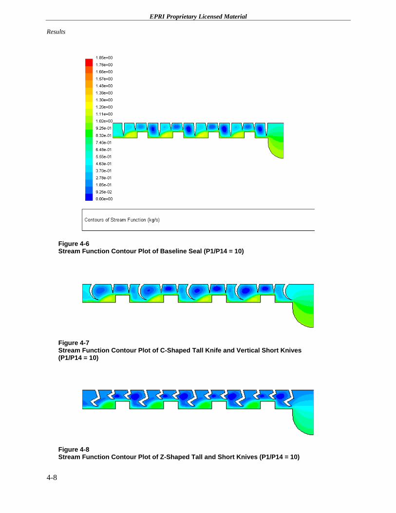
Figures 4-6 through 4-15 show the contours of stream function for all of the designs analyzed. For a 2-D flow, the stream function, ψ, is defined so that:
Eq. 4-1
The value of ψ is constant along a streamline. The difference between constant values of stream function defining two streamlines is the mass rate of flow between the streamlines.
Note: All images are plotted with the same contour range of 0–1.85 kg/sec. Blue represents low mass flow rate, and red indicates a higher mass flow rate.
It can easily be observed that the curvature of the seal forces a different type of flow path compared to the vertical baseline seals, even in cases where the leakage flow increases. Figure 4-16a through 4-16c shows the velocity vectors of the Z seal, C seal with two short knives, and C seal with three short knives, respectively. It is noted that the C seal is able to direct the flow toward the stator or the seal element and reduce the kinetic energy carryover to the next chamber. Also noted is the presence of turbulent vortices and the tortuous path taken by the flow in Figure 4-16c.
Analysis of the numerical simulations has yielded the following observations:
• The CFD analysis indicates that the curved shapes for the knives could result in improved seal performance. This can be explained on the basis that the flow direction is easily altered using a C-shape for the knife, the degree of alteration being dependent on the curvature of the C. Further study would be required to optimize the curvature so that flow path modifications produce the desired effects while maintaining the structural integrity of the seal.
• The velocity vectors are more successfully directed into the rotor and/or the walls of the knives in the case of the C-shaped design as compared to the straight or Z-shaped knife designs.
4-5

EPRI Proprietary Licensed Material Results
Figure 4-4 Percent Change in Leakage of New Labyrinth Designs Compared to an Undamaged Vertical Knife Configuration as Shown in Figure 2-1
4-6

EPRI Proprietary Licensed Material
Results
Figure 4-5 Percent Change in Leakage of Undamaged Curved Seal Configurations Relative to a Damaged Vertical Knife Configuration
4-7
EPRI Proprietary Licensed Material Results
Figure 4-6 Stream Function Contour Plot of Baseline Seal (P1/P14 = 10)
Figure 4-7 Stream Function Contour Plot of C-Shaped Tall Knife and Vertical Short Knives (P1/P14 = 10)
Figure 4-8 Stream Function Contour Plot of Z-Shaped Tall and Short Knives (P1/P14 = 10)
4-8

EPRI Proprietary Licensed Material
Results
Figure 4-9 Stream Function Contour Plot of C-Shaped One Tall and Two Short Sharp Knives (P1/P14 = 10)
Figure 4-10 Stream Function Contour Plot of C-Shaped One Tall and Three Short Sharp Knives (P1/P14 = 10)
Figure 4-11 Stream Function Contour Plot of C-Shaped One Tall and Two Short Flat Knives (P1/P14 = 10)
Figure 4-12 Stream Function Contour Plot of C-Shaped One Tall and Three Short Flat Knives (P1/P14 = 10)
4-9

EPRI Proprietary Licensed Material Results
Figure 4-13 Stream Function Contour Plot of Deformed Vertical Knife (P1/P14 = 10)
Figure 4-14 Stream Function Contour Plot of Deformed C-Shaped One Tall and Two Short Flat Knives (P1/P14 = 10)
Figure 4-15 Stream Function Contour Plot of Deformed C-Shaped One Tall and Three Short Flat Knives (P1/P14 = 10)
4-10

EPRI Proprietary Licensed Material
Results
Figure 4-16 Velocity Vectors for the New Seal Designs (Pressure Ratio = 10)
4-11

EPRI Proprietary Licensed Material Results
Structural Analysis
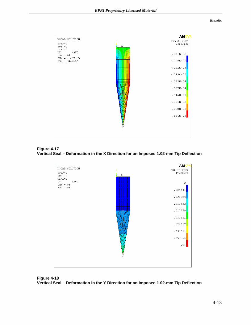
The structural analyses were performed using the ANSYS commercial finite-element analysis tool, assuming elastic behavior of the seal elements. For these analyses, a displacement of 1.02 mm (0.040 inches) was imposed at the tip of each seal knife. This displacement was estimated to be that of the rotor as it goes through its various critical speeds during a turbine startup. The resultant stresses on each knife element and the final deflection shape were studied as a preliminary evaluation of the strength and flexibility of the baseline seals and the new seal knife designs.
Figures 4-17 and 4-18 show the elastic deformation contour plots of a baseline seal knife in the X and Y directions, respectively. Figures 4-19 and 4-20 show the stresses in the X and Y directions for a baseline seal knife. As can be expected, the baseline vertical seal knife does not produce any significant deformations in the X direction, deforming principally in the Y direction as a result of the prescribed displacement boundary condition. The stresses produced in the tips exceed the material’s yield stresses and would lead to the conclusion that this seal’s tip would be deformed permanently, as is typically observed in actual seal assemblies. For elastic deformation, the rub force responsible for the displacement would be distributed uniformly throughout the seal; therefore, the seal would be able to sustain a large force after deformation. As noted previously, the relatively high compressive stiffness could be damaging to the shaft as well as produce a permanent deformation on the seal tip, thus increasing the seal clearance gap (that is, area).
Figures 4-21 and 4-22 show the deformation of the C-shaped sharp tip seal in the X and Y directions, respectively. Figures 4-23 and 4-24 show the stresses produced in the X and Y directions of the C-shaped sharp tip seal. Because of the very small cross-sectional area at the extreme tip, the deformation is principally local to the sharp tip. This results in negligible deflections in the X direction for this design. The stresses produced in the tips are also high—in fact, they exceed the material’s yield strength—and leads to the conclusion that this seal’s tip is deformed permanently.
Figures 4-25 and 4-26 show the deformation of the flat-tipped C seal in the X and Y directions, respectively. Figures 4-27 and 4-28 show the stresses in the X and Y directions, respectively. The contact force that produces a deformation of 1.02 mm (0.040 inches) in the Y direction produces a deformation of more than 1.52 mm (0.06 inches) in the X direction. This analysis indicates that a flat-tipped C seal with a flat edge would be compliant compared to vertical seals in a shaft rub situation. Due to the inherent flexibility of C seals, a larger circumferential portion of the seal would come in contact with the shaft (steps) during a rub. As a result of reduced peak contact force, damage to the shaft would be reduced or avoided compared to that of a standard vertical labyrinth. If a rub event occurs under normal operation during which the seal flow path has high pressure steam, local steam pressure on the rotor would increase and possibly restrain shaft orbital motion. Even if the contribution is less significant, this feature would not be available in a vertical seal because of lack of compliance. The primary concern is the high stress levels on the seal knives, which could lead to failure or significant plastic deformation. Using advanced materials that allow the seal to withstand large elastic deformations can mitigate or eliminate this concern.
4-12
EPRI Proprietary Licensed Material
Results
Figure 4-17 Vertical Seal – Deformation in the X Direction for an Imposed 1.02-mm Tip Deflection
Figure 4-18 Vertical Seal – Deformation in the Y Direction for an Imposed 1.02-mm Tip Deflection
4-13

EPRI Proprietary Licensed Material Results
Figure 4-19 Vertical Seal – Stress in the X Direction for an Imposed 1.02-mm Tip Deflection
Figure 4-20 Vertical Seal – Stress in the Y Direction for an Imposed 1.02-mm Tip Deflection
4-14

EPRI Proprietary Licensed Material
Results
Figure 4-21 C-Shaped Sharp Tip Seal – Deformation in the X Direction for an Imposed 1.02-mm Tip Deflection
Figure 4-22 C-Shaped Sharp Tip Seal – Deformation in the Y Direction for an Imposed 1.02-mm Tip Deflection
4-15

EPRI Proprietary Licensed Material Results
Figure 4-23 C-Shaped Sharp Tip Seal – Stress in the X Direction for an Imposed 1.02-mm Tip Deflection
Figure 4-24 C-Shaped Sharp Tip Seal – Stress in the Y Direction for an Imposed 1.02-mm Tip Deflection
4-16

EPRI Proprietary Licensed Material
Results
Figure 4-25 C-Shaped Flat Tip Seal – Deformation in the X Direction for an Imposed 1.02-mm Tip Deflection
Figure 4-26 C-Shaped Flat Tip Seal – Deformation in the Y Direction for an Imposed 1.02-mm Tip Deflection
4-17

EPRI Proprietary Licensed Material Results
Figure 4-27 C-Shaped Flat Tip Seal – Stress in the X Direction for an Imposed 1.02-mm Tip Deflection
Figure 4-28 C-Shaped Flat Tip Seal – Stress in the Y Direction for an Imposed 1.02-mm Tip Deflection
4-18
EPRI Proprietary Licensed Material
Results
The current analysis therefore indicates an advantage to the C-shaped knife with a flat end for the following reasons:
• Flow analysis using CFD shows that the curved seal can change the flow path, depending on the degree of curvature of the seal. This property can be incorporated into the design process to establish leakage flow paths that create stagnation points and larger total pressure drops across each knife, with the net effect of reduced leakage flow. This larger pressure drop is in addition to that created by the turbulent vortices and other non-isentropic energy conversions that are present in the baseline seal.
• Structurally, the curved flat-tipped C seal is expected to have much more flexibility than a vertical seal, resulting in reduced damage to itself or to the shaft. In addition, new knife materials may be used that allow greater elastic deformation of the C seal design, taking advantage of its inherently more compliant design. For example, fiber-reinforced composites could be used that allow labyrinth seals to be engineered with custom properties at selected locations. With this technique, the seal could maintain its flexibility without reaching its yield stresses or ultimate strength.
4-19


EPRI Proprietary Licensed Material
5 CONCLUSIONS
Three new labyrinth seal knife designs with specific features that address leakage reduction and reduced damage due to potential turbine shaft rubs have been evaluated using computational fluid dynamics and finite-element modeling. Based on this Phase 1 research, one seal configuration composed of a number of circular profile knives with a flat tip feature has been determined to have the best performance based on leakage and seal compliance criteria.
The following are the primary results and conclusions for the flat-tipped C seal design:
• Design features for the new seals are based on the following principles:
– Smaller clearance gaps result in lower steam leakage levels. While this is true for any seal, the emphasis in the current research is on achieving and maintaining smaller clearance gaps for the lifetime of the seal.
– Conformal flexibility of a seal is essential to achieving superior performance compared to a standard vertical seal, especially when the seal must withstand large radial contact forces caused by shaft rubs.
• The following leakage reduction mechanisms in a labyrinth seal were identified:
– Turbulent and viscous losses that reduce the total pressure available to induce fluid flow through the seal.
– A rapidly changing path taken by the fluid through a seal, resulting in turbulent eddies within seal cavities.
– Local flow stagnations are a major loss mechanism.
– The axial position of the seal knives relative to the steps can be used to reduce leakage primarily through increased flow stagnation and a steep flow path curvature.
• The seal recommended for future studies has a compliant curved profile (flat-tipped C seal) that could allow for elastic deformation when contacted by the shaft during a rub incident.
– Based on flow physics, a curved knife profile can modify the leakage flow path, particularly directing the flow toward stagnation points. Compared to a baseline seal that is damaged by a shaft rub, the new design (flat-tipped C + CCC) predicts a leakage reduction of about 65% for pressure ratios between 2 and 10.
– Based on structural analysis, a curved seal with a flat edge shows more flexibility for the same vertical displacement. Concerns regarding the strength of the seal due to the bending stresses must be addressed in future research by applying innovative materials such as reinforced composites.
5-1

EPRI Proprietary Licensed Material Conclusions
Recommendations
It is recommended that subsequent phases of research on these advanced labyrinth seal configurations involve the following tasks:
• Assessment of viable materials and the manufacturing feasibility of the proposed C-shaped knife configuration, with particular emphasis on achieving the desired elastic deformation characteristics.
• Verification and optimization of the leakage flow reduction achieved with the C-shaped knife configuration using the existing static test rig at USTI, including the effects of possible seal deformation following a rub.
• Experimental verification of performance improvement derived from the C-shaped knife configuration in a full-scale rotating test rig, including verification of improved rotordynamic stability.
5-2

EPRI Proprietary Licensed Material
6 REFERENCES
1. H.L. Stocker, “Determining and Improving Labyrinth Seal Performance in Current and Advanced High Performance Gas Turbines,” AGARD Conference Proceedings no. 237, Seal Technology in Gas Turbine Engines, April 1978.
2. G.L. Morrison and D. Chi, “Incompressible Flow in Stepped Labyrinth Seals,” ASME Paper 85-FE-4, Joint ASME/ACSE Applied Mechanics, Bio-Engineering, and Fluids Engineering. Conference, Albuquerque, NM, June 1985.
3. J.S. Wyler, “Design and Testing of a New Double Labyrinth Seal,” ASME Paper 81-Lub-58, ASME Winter Annual Meeting, Washington, D.C., November 1981.
4. H.L. Stocker, “Advanced Labyrinth Seal Design Performance for High Pressure Ratio Gas Turbines,” ASME Paper 75-WA/GT-22, ASME Winter Annual Meeting, Houston, TX, November/December 1975.
5. R.C. Hendricks, T.A. Griffin, T.R. Kline, K.R. Csavina, A. Pancholi, and D. Sood, “Relative Comparison between Baseline Labyrinth and Dual-Brush Compressor Discharge Seals in a T-700 Engine Test,” NASA Technical Memorandum 106360, 39th International Gas Turbine and Aeroengine Congress and Exposition by ASME, Hague, The Netherlands, June 1994.
6. U.S. Patents: 4,420,161; 5,224,713; 5,244,216; 5,639,095; 6,394,459; 6,644,667; 6,435,513; 6,257,586; 6,131,911; 6,131,910; 6,105,967; 6,045,134; 6,027,121; and 5,749,584.
7. F.L. Heidrich, “Water Flooded Single Screw Process Compressor Technology,” Dresser-Rand E-Tech, NY.
8. G.L. Morrison et al., “Labyrinth Seals for Incompressible Flow – Final Report,” NASA Contract Report CR-170938, November 1983.
9. W.J. Kearton and T.H. Keh, “Leakage of Air Through Labyrinth Glands of Staggered Type,” IME Proceedings, vol. 166, no. 2, 1952.
10. H.M. Martin, “Labyrinth Packings,” Engineering, vol. 85, January 1908.
11. C.A. Meyer and J.A. Lowrie, “The Leakage Through Straight and Aslant Labyrinths and Honeycomb Seals,” ASME Paper 74-WA/PTC-2.
12. D.L. Tipton, T.E. Scott, and R.E. Vogel, “Analytical and Experimental Development of a Design Model for Labyrinth Seals,” Air Force Wright Aeronautical Labs Report TR-85-2103 vol. 3, January 1986.
13. Z. Yizheng and H. Feng, “Analysis of Leakage Characteristics of Labyrinth Seals,” Chinese Journal of Aeronautics, vol. 3, no. 4, November 1990.
14. K. Miyake and W.C. Duh, “Leakage Characteristics of Labyrinth Seals,” J. of the Chinese Society of Mechanical Engineers, vol. 11, no. 4, August 1990.
6-1
EPRI Proprietary Licensed Material References
15. K. Komotori and K. Miyake, “Leakage Characteristics of Labyrinth Seals with High Rotating Speed,” Tokyo Joint Gas Turbine Congress, May 1977.
16. D.L. Rhode and G.H. Nail, “Computation of Cavity-by-Cavity Flow Development in Generic Labyrinth Seals,” J. of Tribology Trans. – ASME, vol. 114, 01 January 1992, p. 47–51.
17. D.L. Rhode, S.H. Ko, and G.L. Morrison, “Leakage Optimization of Labyrinth Seals using a Navier-Stokes Code,” Tribology Trans., vol. 37, part 1, January 1994, p. 105–110.
18. D.L. Rhode and R.I. Hibba, “New Model for Flow over Open Cavities and Assessment of Seal Leakage,” J. of Propulsion and Power, 8(2), March/April 1992, p. 398–402.
19. M.A. Leschziner and K.P. Dimitriadis, “Computation of 3-Dimensional Turbulent Flow in Non-orthogonal Junctions by a Branch-coupling Method,” Computational Fluids, 17(2), 1989, p. 271–296.
20. D.L. Rhode, J.A. Demko, and U.K. Traegner et al., “Prediction of Incompressible Flow in Labyrinth Seals,” J. of Fluid Engg. Trans. ASME, 108(1), March 1996, p. 19–25.
21. J. Denecke, V. Schramm, S. Kim, and S. Wittig, “Influence of Rub-grooves on Labyrinth Seal Leakage,” ASME, IGTI, Turbo-Expo-Publication-IGTI, vol. 3B, 2002, p. 771–779.
22. D.L. Rhode, S.H. Ko, and G.L. Morrison, “Experimental and Numerical Assessment of an Advanced Labyrinth Seal,” Tribology Trans., vol. 37, part 4, 1994, p. 743–750.
23. D.L. Rhode and M.J. Guidry, “A New Approach for Stabilizing Labyrinth Seal Leakage,” Tribology Trans., vol. 36, part 2, 1993, p. 219–224.
24. J.A. Demko, G.L. Morrison, and D.L. Rhode, “The Prediction and Measurement of Incompressible Flow in a Labyrinth Seal,” J. of Engg. for Gas Turbines and Power, vol. 111, October 1989, p. 697–702.
25. J.A. Demko et al., “Prediction of Incompressible Flow in Labyrinth Seals,” J. of Fluids Engg., vol. 108, March 1996, p. 19–25.
26. E.A. Baskharone and A. Ghali, “Theoretical vs. Experimental Rotordynamic Coefficients of Incompressible Flow Labyrinth Seals,” J. of Propulsion and Power, vol. 10, September/October 1994, p. 721–728.
27. A. Pfau et al., “Unsteady Flow Interactions within the Inlet Cavity of a Turbine Rotor Tip Labyrinth Seal,” ASME, IGTI, Turbo-Expo-Publication-IGTI, vol. 6A, 2003, p. 187–199.
28. M. Vance John, J.J. Zierer, Jr., and E.M. Conway, “Effect of Straight-through Labyrinth Seals on Rotordynamics,” Vibration of Rotating Systems-ASME, Design Engg. Division-Publication-DE, vol. 60, 1993, p. 159–171.
29. D.W. Childs and J.K. Scharrer, “Theory vs. Experiment for the Rotordynamic Coefficient of Labyrinth Gas Seals: Part II – a Comparison to Experiment,” Trans. ASME, J. of Vibr. Acous. Stress Reliability Des., vol. 110, no. 3, 1988, p. 281–287.
30. J.A. Demko, G.L. Morrison, and D.L. Rhode, “Effect of Shaft Rotation on the Incompressible Flow in a Labyrinth Seal,” J. of Propulsion and Power, 6(2), March/April 1990, p. 171–176.
31. C. Brennen, “On the Flow in an Annulus Surrounding a Whirling Cylinder,” J. of Fluid Mechanics, vol. 75, part 1, 1976, p. 173–191.
6-2

EPRI Proprietary Licensed Material
Summary of Calculated Leakage Flows for Various Labyrinth Configurations
32. B. Robic, “Experimental and Numerical Analysis of the Effect of Swirl on the Pressure Field in Whirling Annular and Labyrinth Seals,” Doctoral Thesis, Texas A&M University, May 1999.
33. W. Washka, S. Wittig, S. Kim, and T. Shere, “Heat Transfer and Leakage in High Speed Rotating Stepped Labyrinth Seals,” AGARD, Heat Transfer and Cooling in Gas Turbines, February 1993.
34. J.B. Brownell, J.A. Millward, and R.J. Parker, “Non-intrusive Investigations into Life-size Labyrinth Seal Flow Fields,” J. of Engg. for Gas Turbines and Power, vol. 111, April 1989, p. 335–342.
35. G.L. Morrison, M.C. Johnson, and R.E. DeOtte, “Experimental Investigation of an Eccentric Labyrinth Seal Velocity Filed Using 3-D Laser Doppler Anemometry,” Presented at the 1990 ASME Annual Meeting, Dallas, TX, November 1990, FED Vol. 101, Fluid Machinery Components Book No. G00558, p. 61–71.
36. H.L. Stocker, D.M. Cox, and G.F. Holle, “Aerodynamic Performance of Conventional and Advanced Design Labyrinth Seals with Solid-Smooth, Abradable, and Honeycomb Lands,” NASA Contract Report, CR-135307, November 1977.
37. D.L. Rhode and M.J. Guidry, “Importance of Labyrinth Seal Through-flow Deflection for Enlarging Clearance without Increasing Leakage,” Tribology Trans., vol. 36, part 3, 1993, p. 477–483.
38. A.D. Vakili, A.J. Meganathan, M.A. Michaud, and S. Radhakrishnan, “An Experimental and Numerical Study of Labyrinth Seal Flow,” Paper No. 2005-68224, Proceedings of ASME Turbo Expo 2005, Reno, NV, June 6–9, 2005 (to be presented).
39. M. Michaud, A.D. Vakili, A.J. Meganathan, R. Zielke, L. Shuster, and J. Terrell, “An Experimental Study of Labyrinth Seal Flow,” Paper No. 2003-40097, Proceedings of ASME IJPGC, 2003 International Joint Power Conference, Atlanta, GA, June 16–19, 2003.
40. M. Michaud, “An Experimental Study of Labyrinth Seal Flow,” MS Thesis, University of Tennessee, August 2002.
6-3


EPRI Proprietary Licensed Material
A-1
A SUMMARY OF CALCULATED LEAKAGE FLOWS FOR VARIOUS LABYRINTH CONFIGURATIONS
Appendix A contains results of two-dimensional axisymmetric CFD calculations of leakage flow for the various seal configurations shown in Figures 3-2 through 3-10. Pressure ratios of 2.0 through 10.0 were used in increments of 2.0. Table A-1 contains the nominal calculation results in units of kilograms/second flow rate at the five pressure ratios. The column titles describe the seal configuration and refer to the appropriate figure in Section 3 of the report. Table A-2 shows the same information as Table A-1 but as percentage difference in predicted leakage relative to the baseline labyrinth configuration of Figure 3-2. Table A-3 contains the calculation results in units of kilograms/second flow rate for labyrinth seal configurations that are damaged as shown in Figures 3-8 through 3-10. The damage corresponds to the increased clearance associated with a turbine shaft rub event. The final column in Table A-3 is for the undamaged labyrinth seal configuration shown in Figure 3-7, assuming that, following a turbine rub, the knife shape would be restored because of the inherent compliance of the design. Finally, Table A-4 contains the same information as Table A-3 but shown as percentage difference in flow rate relative to the baseline undamaged labyrinth configuration.

EPRI Proprietary Licensed Material Summary of Calculated Leakage Flows for Various Labyrinth Configurations
Table A-1 Nominal Leakage Flow (kg/s) Based on Two-Dimensional CFD Calculation for Seal Geometries Identified in Section 3
Pressure Ratio
Across Seal
Baseline Design, Vertical Knives
(Figure 3-1)
Tall C-Knife with Two
Short Vertical Knives
(Figure 3-2)
Tall C-Knife with Two Short
Vertical Knives (50% Clearance)
Z-Knives (Figure
3-3)
Tall C-Knife with Two Short C-
Knives, Sharp-Tipped
(Figure 3-4)
Tall C-Knife with Three Short C-Knives, Sharp-
Tipped (Figure 3-5)
Tall C-Knife with Two Short C-Knives, Flat-
Tipped (Figure 3-6)
Tall C-Knife with Three
Short C-Knives, Flat-Tipped (Figure 3-7)
2.0 0.09 0.10 0.06 0.10 0.12 0.08 0.12 0.09
4.0 0.20 0.22 0.13 0.22 0.23 0.16 0.23 0.18
6.0 0.30 0.33 0.19 0.34 0.35 0.24 0.31 0.26
8.0 0.40 0.44 0.26 0.45 0.47 0.31 0.41 0.34
10.0 0.50 0.55 0.32 0.56 0.52 0.39 0.50 0.41
Table A-2 Percent Change in Calculated Leakage Flow Relative to Baseline Vertical Knife Design*
Pressure Ratio
Across Seal
Baseline Design, Vertical Knives
(Figure 3-1)
Tall C-Knife with Two
Short Vertical Knives
(Figure 3-2)
Tall C-Knife with Two Short Vertical
Knives (50% Clearance)
Z-Knives (Figure
3-3)
Tall C-Knife with Two Short C-
Knives, Sharp-Tipped
(Figure 3-4)
Tall C-Knife with Three Short C-Knives, Sharp-
Tipped (Figure 3-5)
Tall C-Knife with Two Short C-
Knives, Flat-Tipped
(Figure 3-6)
Tall C-Knife with Three Short C-
Knives, Flat-Tipped
(Figure 3-7)
2.0 0.0 13.6 -32.8 14.2 28.8 -10.5 27.9 -0.9
4.0 0.0 11.4 -33.4 13.9 19.8 -16.2 17.4 -10.0
6.0 0.0 11.4 -34.3 13.6 19.1 -19.4 3.9 -13.4
8.0 0.0 11.0 -34.7 13.1 19.5 -21.2 2.1 -15.5
10.0 0.0 10.7 -34.9 12.6 4.4 -22.3 1.6 -16.7
*negative value = reduction in leakage
A-2

EPRI Proprietary Licensed Material
Summary of Calculated Leakage Flows for Various Labyrinth Configurations
A-3
Table A-3 Nominal Leakage Flow (kg/s) Based on Two-Dimensional CFD Calculation of Damaged Seal Configurations
Pressure Ratio Across
Seal
Undamaged Baseline Vertical
Knives (Figure 3-1)
Damaged Baseline Vertical Knives
(Figure 3-8)
Tall C-Knife with Two Short C-Knives, Flat-
Tipped, Damaged (Figure 3-9)
Tall C-Knife with Three Short C-Knives, Flat-
Tipped, Damaged (Figure 3-10)
Tall C-Knife with Three Short C-Knives, Flat-Tipped, Undamaged
(Figure 3-7)
2.0 0.09 0.24 0.27 0.22 0.09
4.0 0.20 0.52 0.59 0.48 0.18
6.0 0.30 0.79 0.89 0.72 0.26
8.0 0.40 1.05 1.17 0.96 0.34
10.0 0.50 1.31 1.48 1.20 0.41
Table A-4 Percent Change in Calculated Leakage Flow Relative to Vertical Knife Design*
Relative to Undamaged Vertical Relative to
Damaged Vertical
Pressure Ratio Across Seal
Undamaged Baseline Vertical
Knives (Figure 3-1)
Damaged Baseline Vertical Knives
(Figure 3-8)
Tall C-Knife with Two Short C-Knives, Flat-
Tipped, Damaged (Figure 3-9)
Tall C-Knife with Three Short C-Knives, Flat-
Tipped, Damaged (Figure 3-10)
Tall C-Knife with Three Short C-Knives, Flat-Tipped, Undamaged
(Figure 3-7)
2.0 0.0 166.8 202.1 142.2 -62.9
4.0 0.0 166.4 200.0 144.0 -66.2
6.0 0.0 165.5 199.2 142.7 -67.4
8.0 0.0 164.4 195.1 141.9 -68.1
10.0 0.0 163.8 197.9 142.1 -68.4
*negative value = reduction in leakage


Electric Power Research Institute • 3412 Hillview Avenue, Palo Alto, California 94304 • PO Box 10412, Palo Alto, California 94303 • USA800.313.3774 • 650.855.2121 • [email protected] • www.epri.com
WARNING: This Document containsinformation classified under U.S. ExportControl regulations as restricted fromexport outside the United States. You
are under an obligation to ensure that you have alegal right to obtain access to this informationand to ensure that you obtain an export licenseprior to any re-export of this information. Specialrestrictions apply to access by anyone that is nota United States citizen or a Permanent UnitedStates resident. For further informationregarding your obligations, please see theinformation contained below in the section titled“Export Control Restrictions.”
© 2005 Electric Power Research Institute (EPRI), Inc.All rights reserved. Electric Power ResearchInstitute and EPRI are registered service marks of the Electric Power Research Institute, Inc.
Printed on recycled paper in the United States of America
Program: 1011932
Steam Turbines, Generators,and Balance-of-Plant
The Electric Power Research Institute (EPRI)
The Electric Power Research Institute (EPRI), withmajor locations in Palo Alto, California, andCharlotte, North Carolina, was established in 1973as an independent, nonprofit center for publicinterest energy and environmental research. EPRIbrings together member organizations, the Institute’sscientists and engineers, and other leading expertsto work collaboratively on solutions to thechallenges of electric power.These solutions spannearly every area of power generation, delivery, anduse, including health, safety, and environment. EPRI’smembers represent over 90% of the electricitygenerated in the United States. Internationalparticipation represents nearly 15% of EPRI’s totalR&D program.
Together . . . Shaping the Future of Electricity
Export Control RestrictionsAccess to and use of EPRI Intellectual Property is grantedwith the specific understanding and requirement thatresponsibility for ensuring full compliance with all applicableU.S. and foreign export laws and regulations is beingundertaken by you and your company. This includes anobligation to ensure that any individual receiving accesshereunder who is not a U.S. citizen or permanent U.S.resident is permitted access under applicable U.S. and foreignexport laws and regulations. In the event you are uncertainwhether you or your company may lawfully obtain access tothis EPRI Intellectual Property, you acknowledge that it isyour obligation to consult with your company’s legal counselto determine whether this access is lawful. Although EPRImay make available on a case by case basis an informalassessment of the applicable U.S. export classification forspecific EPRI Intellectual Property, you and your companyacknowledge that this assessment is solely for informationalpurposes and not for reliance purposes. You and yourcompany acknowledge that it is still the obligation of you andyour company to make your own assessment of theapplicable U.S. export classification and ensure complianceaccordingly. You and your company understand andacknowledge your obligations to make a prompt report toEPRI and the appropriate authorities regarding any access toor use of EPRI Intellectual Property hereunder that may bein violation of applicable U.S. or foreign export laws orregulations.