The Need for Low-Loss Multifiber...
12
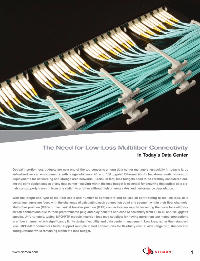
www.siemon.com 1 The Need for Low-Loss Multifiber Connectivity In Today’s Data Center Optical insertion loss budgets are now one of the top concerns among data center managers, especially in today’s large virtualized server environments with longer-distance 40 and 100 gigabit Ethernet (GbE) backbone switch-to-switch deployments for networking and storage area networks (SANs). In fact, loss budgets need to be carefully considered dur- ing the early design stages of any data center—staying within the loss budget is essential for ensuring that optical data sig- nals can properly transmit from one switch to another without high bit error rates and performance degradation. With the length and type of the fiber cable and number of connectors and splices all contributing to the link loss, data center managers are faced with the challenge of calculating each connection point and segment within their fiber channels. Multi-fiber push on (MPO) or mechanical transfer push on (MTP) connectors are rapidly becoming the norm for switch-to- switch connections due to their preterminated plug and play benefits and ease of scalability from 10 to 40 and 100 gigabit speeds. Unfortunately, typical MPO/MTP module insertion loss may not allow for having more than two mated connections in a fiber channel, which significantly limits design flexibility and data center management. Low loss, rather than standard loss, MPO/MTP connectors better support multiple mated connections for flexibility over a wide range of distances and configurations while remaining within the loss budget.
Transcript of The Need for Low-Loss Multifiber...
www.siemon.com 1
The Need for Low-Loss Multifiber Connectivity In Today’s Data Center
Optical insertion loss budgets are now one of the top concerns among data center managers, especially in today’s large
virtualized server environments with longer-distance 40 and 100 gigabit Ethernet (GbE) backbone switch-to-switch
deployments for networking and storage area networks (SANs). In fact, loss budgets need to be carefully considered dur-
ing the early design stages of any data center—staying within the loss budget is essential for ensuring that optical data sig-
nals can properly transmit from one switch to another without high bit error rates and performance degradation.
With the length and type of the fiber cable and number of connectors and splices all contributing to the link loss, data
center managers are faced with the challenge of calculating each connection point and segment within their fiber channels.
Multi-fiber push on (MPO) or mechanical transfer push on (MTP) connectors are rapidly becoming the norm for switch-to-
switch connections due to their preterminated plug and play benefits and ease of scalability from 10 to 40 and 100 gigabit
speeds. Unfortunately, typical MPO/MTP module insertion loss may not allow for having more than two mated connections
in a fiber channel, which significantly limits design flexibility and data center management. Low loss, rather than standard
loss, MPO/MTP connectors better support multiple mated connections for flexibility over a wide range of distances and
configurations while remaining within the loss budget.
WP_
Low
Loss
_ Re
v. C
10/
14
WP_LowLoss_D_B 10/13/14 2:08 PM Page 2

LO
W L
OS
S M
UL
TIF
IBE
R
2 www.siemon.com
Evolving Data Center Architectures Impact Loss
Traditional three-tier Layer 3 switch architectures have been common practice in the data center environment for several
years. These traditional architectures consist of core network and SAN switches located in the main distribution area (MDA);
aggregation switches located in the MDA, intermediate distribution area (IDA) or horizontal distribution area (HDA); and
access switches located in the HDA (see Figure 1).
Figure 1: Traditional three-tier switch architecture per TIA-942 data center standards.
With multiple switch tiers and fiber backbone speeds of 10 gigabits per second (Gb/s), the distance and data rates between
switches have remained short enough for most data centers to maintain two or more connectors without exceeding optical
link loss budgets. However, traditional three-tier architectures are no longer ideal for large virtualized data centers.
While the traditional three-tier architecture was well suited for data traffic between servers that reside on the same access
switch, it does not adequately support the non-blocking, low-latency, high-bandwidth requirements of today’s large virtualized
data centers that divide single physical servers into multiple isolated virtual environments. Non-blocking refers to having suf-
ficient bandwidth so that any port can communicate with any other port at the full bandwidth capacity of the port, while latency
refers to the amount of time it takes for a data packet to travel from its source to its destination. With equipment now located
anywhere in the data center, data traffic between two access switches in a three-tier architecture may have to traverse in a
north-south traffic pattern through multiple aggregation and core switches, resulting in an increased number of switch hops
and increased latency.
In a high-bandwidth, virtualized environment, the traditional north-south traffic pattern (switch to switch) causes the problem
of links not having enough bandwidth to support the traffic.
This has many data centers moving to switch fabric architectures that use only two tiers of switches with fewer switch-to-
switch hops. Switch fabrics provide lower latency and greater bandwidth between any two points by taking advantage of wire-
speed transmissions on the backplanes (port to port) of switches as opposed to uplinks from lower level switch to higher level
switch). This enables dynamic east-west server-to-server traffic where it is needed, eliminating the need for communication
between two servers to travel north-south through multiple switch layers.
WP_LowLoss_D_B 10/13/14 2:08 PM Page 3

www.siemon.com
LO
W L
OS
S M
UL
TIF
IBE
R
3
Fat-tree switch fabrics, also referred to as a leaf and spine architectures, are one of the most common switch fabrics being
deployed in today’s virtualized data center. The fat-tree architecture consists of interconnection (spine) switches placed in
the MDA and access (leaf) switches placed in the HDA or EDA that each connect, or uplink, to every interconnection switch
in a mesh, typically via optical fiber (see Figure 2).
While the fat-tree flattened architecture leverages the reach of standards-based optical fiber cabling to establish large
numbers of active connections between fewer switches, these new data center designs often result in longer distances
between interconnection and access switches. These longer fiber runs can be difficult to deploy in data center pathways, and
adding new access switches presents the challenge of adding additional long fiber runs to already populated pathways.
To maintain flexibility and manageability, ease deployments and upgrades, and limit access to critical switches, many data
center managers are looking to deploy multiple mated pairs that support distribution points or convenient fiber patching areas
(cross connects).
Convenient patching areas
include the use of fiber connect
panels that mirror interconnection
switch ports and connect via
permanent, or fixed, links to fiber
connect panels that mirror access
switch ports (see Figure 3). These
panels can be located in separate
cabinets, which allows the
switches to remain untouched and
secure. They also enable easier
moves, adds and changes
(MACs) by creating an “any to all”
configuration where any switch
port can be connected to any
other switch port by simply
repositioning fiber jumper connec-
tions at the patching area.
Figure 2: Fat-tree switch fabric architecture per the TIA-942-A addendum.
Figure 3: Cross connects can be deployed for ease of manageability, flexibility and/or keeping switches secure.However, the extra mated connections in the backbone channel may require low loss optical fiber connectivity.
WP_LowLoss_D_B 10/13/14 2:08 PM Page 4

LO
W L
OS
S M
UL
TIF
IBE
R
4 www.siemon.com
Figure 4: Top-view of a data center showing the use of cross connects for core SAN and network switch connections in the MDA and serversand access switches in the HDA. A server’s fiber connection can easily be switched from network to SAN via a simple fiber jumper changeat the end of row cross connect.
Unfortunately, the use of these valuable cross connects adds additional connection points and subsequent loss in a fiber channel. Consequently, standard loss MPO/MTP insertion loss values can put data center managers at risk of exceeding theiroptical link loss budgets, often preventing the use of cross connects and requiring continued use of long fiber runs that significantly limit flexibility and complicate MACs and upgrades.
Higher Bandwidth Speeds Impact Loss
One of the key driving factors that is making fiber loss budgets a growing concern in the data center environment is the migration of transmission speeds from 1 Gb/s, to 10 Gb/s, to now 40 and 100 Gb/s for Ethernet-based networks and from 8 Gb/s, to 16 Gb/s, to now 32 Gb/s for Fibre Channel-based SANs.
As speeds increase, insertion loss requirements become more stringent than ever, making the use of cross connects more difficult in most scenarios where standard insertion loss values are used. A closer look at the evolution of Ethernet standardsdemonstrates the impact of speed on insertion loss.
The Institute of Electrical and Electronics Engineers (IEEE) 1000BASE-SX standard (1 GbE) allows for a maximum channelloss of 4.5 dB over 1000 meters of OM3 multimode fiber and 4.8 dB over 1100 meters of OM4. The maximum channel lossfor 10GBASE-SR (10 GbE) was reduced to 2.6 dB over 300 meters of OM3 fiber and 2.9 dB over 400 meters of OM4.
Ideal for larger data centers or when optical fiber is distributed to multiple functional areas or zones, the use of cross
connects at interconnection and/or access switches can also allow for one-time deployment of permanent high-fiber-count
cabling from the MDA to the HDA. This allows for the fiber backbone cabling to be used for various purposes (networking or
SAN) without multiple MACs and simplifies the process of adding new access switches and equipment to the data center.
For example, all it takes to swap a server’s fiber connection from a network connection to a SAN connection is a simple fiber
jumper change at the cross connect located at the end of each row (see Figure 4). ).
WP_LowLoss_D_B 10/13/14 2:08 PM Page 5

www.siemon.com
LO
W L
OS
S M
UL
TIF
IBE
R
5
Figure 5: Per IEEE 802.3ae, a 10 gigabit channel over OM3 fiber has a maximum distance of 300 meters with a maximum loss budget of 2.6 dB.
IEEE 40GBASE-SR4 and 100GBASE-SR10 standards for 40 and 100 GbE over multimode fiber with an 850 nm source now
have more stringent loss requirements for the fiber, which lowers the overall channel loss. As shown in Table 1, for OM3 fiber
cabling, the 40 and 100 GbE standards allows for a channel distance of 100 meters with a maximum channel loss of 1.9 dB,
including a maximum connector loss of 1.5 dB. For OM4 fiber cabling, the distance is increased to 150 meters but with a max-
imum channel loss of 1.5 dB, including a maximum connector loss of 1.0 dB.
Table 1: As speeds have increased from 1 Gb/s to 40 and 100 Gb/s, maximum channel distance and loss has decreased significantly
It should be noted that current TIA and ISO standards require a minimum of OM3 fiber, while TIA recommends the use of
OM4 due to its longer transmission capabilities. In fact, the upcoming 100GBASE-SR4 standard that will use eight fibers (i.e.,
four transmitting and four receiving) at 25 Gb/s is anticipated to be supported by OM4 fiber to 100 meters, but to only 70 me-
ters using OM3.
Typical MPO/MTP connectors, which are required for 40 and 100 GbE deployments have insertion loss values that range
from 0.3 dB to 0.5 dB. Typical LC multimode fiber connectors have loss values that range from 0.3 dB to 0.5 dB. While bet-
ter than the allowed 0.75 dB TIA value, typical connector loss still limits how many connections can be deployed in 10, 40
and 100 GbE channels. For example, with an LC connector loss of 0.5 dB, a 300-meter 10 GbE channel over OM3 fiber can
include only three connectors with no headroom. Having just two or three connections prevents the use of cross connects
at both interconnection (MDA) and access switches (HDA).
Based on the 0.75 dB maximum acceptable connector loss and the 3.5dB/km maximum fiber loss specified in TIA-568-C.0-
2 standards, the loss values for 10 GbE assume two connection points in the channel with connector pairs contributing a total
of 1.5 dB allocated for insertion loss and the fiber contributing a total of 1.1 dB for OM3 and 1.4 dB for OM4, respectively.
For example, Figure 5 shows a two-connector 10 GbE channel using OM3 fiber and maximum loss values per the TIA and
IEEE standards.
WP_LowLoss_D_B 10/13/14 2:08 PM Page 6
LO
W L
OS
S M
UL
TIF
IBE
R
6 www.siemon.com
Low Loss Fiber Connectivity to the Rescue
Due to improvements in connector technology and manufacturing techniques,
Siemon has succeeded in lowering the loss to 0.20 dB for MTP connectors and
to 0.15 dB (0.1 dB typical) for LC and SC connectors, well below the industry
standard of 0.75 dB and loss values offered by other manufacturers.
For 10 GbE, Siemon low loss LC BladePatch fiber jumpers offer a loss of 0.15 dB
(typical 0.1 dB) and Siemon low loss plug and play MTP to LC or SC modules
offer a loss of 0.35 dB (typical 0.25 dB). For 40 and 100 GbE, Siemon MTP to
MTP pass-through adapter plates and MTP fiber jumpers offer a loss of 0.2 dB.
These lower loss values allow data center managers to deploy more connection
points in fiber channels, enabling the use of distribution points or cross connects
that significantly increase flexible configuration options.
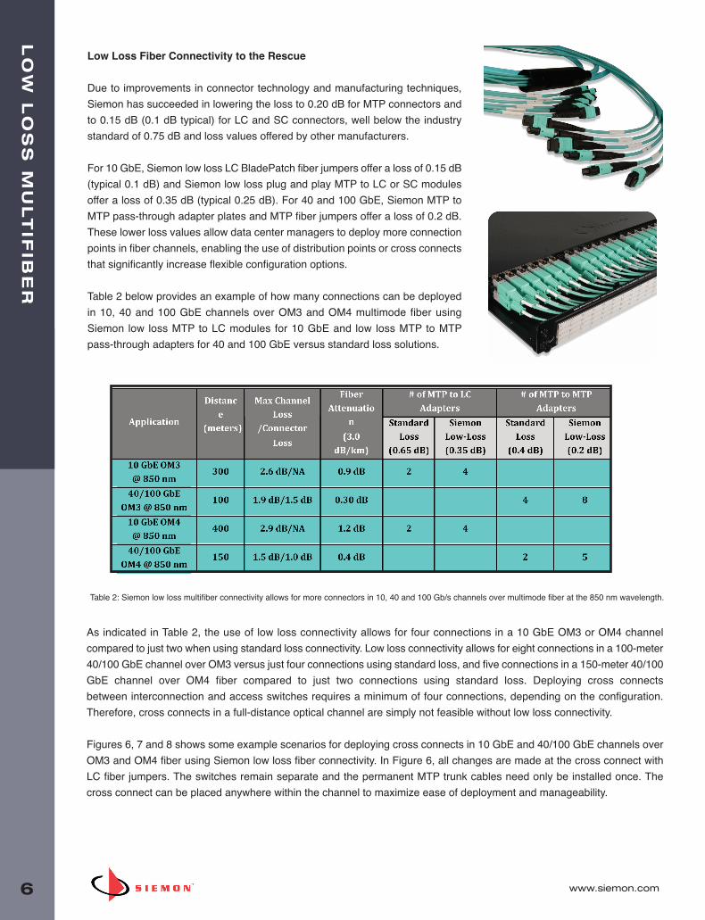
Table 2 below provides an example of how many connections can be deployed
in 10, 40 and 100 GbE channels over OM3 and OM4 multimode fiber using
Siemon low loss MTP to LC modules for 10 GbE and low loss MTP to MTP
pass-through adapters for 40 and 100 GbE versus standard loss solutions.
Table 2: Siemon low loss multifiber connectivity allows for more connectors in 10, 40 and 100 Gb/s channels over multimode fiber at the 850 nm wavelength.
As indicated in Table 2, the use of low loss connectivity allows for four connections in a 10 GbE OM3 or OM4 channel
compared to just two when using standard loss connectivity. Low loss connectivity allows for eight connections in a 100-meter
40/100 GbE channel over OM3 versus just four connections using standard loss, and five connections in a 150-meter 40/100
GbE channel over OM4 fiber compared to just two connections using standard loss. Deploying cross connects
between interconnection and access switches requires a minimum of four connections, depending on the configuration.
Therefore, cross connects in a full-distance optical channel are simply not feasible without low loss connectivity.
Figures 6, 7 and 8 shows some example scenarios for deploying cross connects in 10 GbE and 40/100 GbE channels over
OM3 and OM4 fiber using Siemon low loss fiber connectivity. In Figure 6, all changes are made at the cross connect with
LC fiber jumpers. The switches remain separate and the permanent MTP trunk cables need only be installed once. The
cross connect can be placed anywhere within the channel to maximize ease of deployment and manageability.
WP_LowLoss_D_B 10/13/14 2:08 PM Page 7

www.siemon.com
LO
W L
OS
S M
UL
TIF
IBE
R
7
Figure 6: Four Siemon Low Loss MTP-LC Modules can be deployed in a 10 GbE channel, enabling a cross connect for superior flexibility and manageability.
Figure 7. shows an OM3 40/100 GbE channel with six Siemon low loss MTP-MTP pass-through adapter plates and low loss
trunks. This scenario offers 0.4 dB of headroom and provides even better manageability and security. All changes are made
at the cross connects via MTP fiber jumpers, switches remain separate, and the MTP trunk cables need only be installed
once. Once again, the cross connects can be located anywhere in the data center for maximum flexibility. This allows for one-
time deployment of high fiber-count cabling from the cross connect at the interconnection switch to the cross connect at the
access switch. Adding additional access switches can be accomplished with short fiber runs from the cross connect.
Figure 7: For maximum flexibility, manageability and security, up to eight Siemon low loss MTP-MTP pass-through adapters can be deployedusing low loss trunks in a 100-meter 40/100 GbE switch-to-switch backbone channel over OM3 fiber.
WP_LowLoss_D_B 10/13/14 2:08 PM Page 8
LO
W L
OS
S M
UL
TIF
IBE
R
8 www.siemon.com
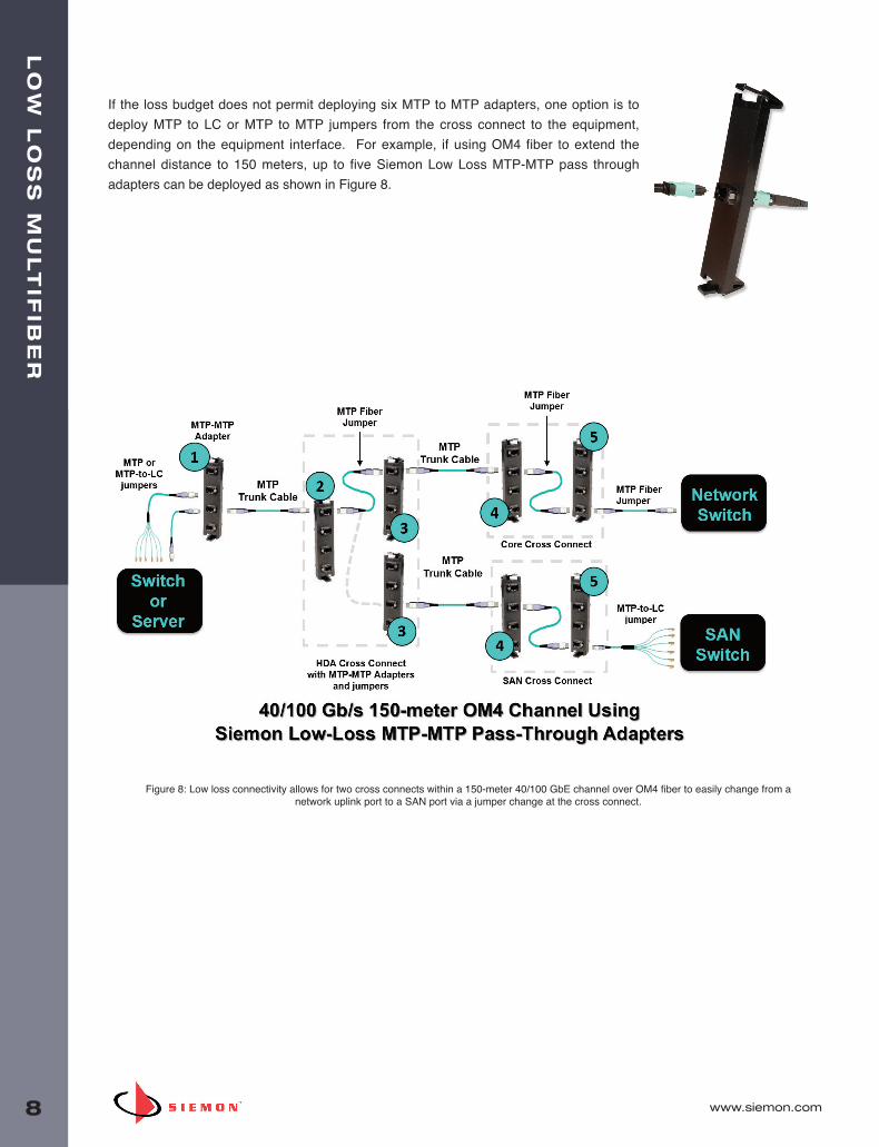
Figure 8: Low loss connectivity allows for two cross connects within a 150-meter 40/100 GbE channel over OM4 fiber to easily change from anetwork uplink port to a SAN port via a jumper change at the cross connect.
If the loss budget does not permit deploying six MTP to MTP adapters, one option is to
deploy MTP to LC or MTP to MTP jumpers from the cross connect to the equipment,
depending on the equipment interface. For example, if using OM4 fiber to extend the
channel distance to 150 meters, up to five Siemon Low Loss MTP-MTP pass through
adapters can be deployed as shown in Figure 8.
WP_LowLoss_D_B 10/13/14 2:08 PM Page 9

www.siemon.com
LO
W L
OS
S M
UL
TIF
IBE
R
9
In addition to enabling more connections in 10, 40 and 100 gigabit Ethernet channels, low loss connectivity provides the same
benefits for Fibre Channel deployments in SANs. For example, a 150-meter 8 Gb/s Fibre Channel (GFC) deployment allows
for up to four Siemon low loss MTP to LC modules yet allows for only two modules when using standard loss
components. Using low loss connectivity to deploy cross connects therefore makes it easy to change server connections from
a network uplink port to a SAN port and vice versa by simply changing a jumper at the cross connect as shown in Figure 9.
Figure 9: Low loss connectivity also supports additional connection points for Fibre Channel, making it easy tochange from a network uplink port to a SAN port by changing a jumper at the cross connect.
WP_LowLoss_D_B 10/13/14 2:08 PM Page 10

LO
W L
OS
S M
UL
TIF
IBE
R
10 www.siemon.com
Table 3 below provides a detailed summary of several Ethernet and Fibre Channel scenarios using Siemon low loss
connectivity versus standard loss connectivity. The blue areas indicate that the loss is within the standards requirements,
while red indicates over budget. As indicated, the maximum operating distance is impacted by the number of connections.
However, low loss connectivity clearly enables more connections in both Ethernet and Fibre Channel fiber links.
Table 3: Siemon low loss fiber enables multiple mated pairs in Ethernet and Fibre Channel applications. * 550 meters is beyond the standard for OM4 but supported by most of today’s equipment
** 0.5 meters is the minimum distance for all Ethernet and FC applications
WP_LowLoss_D_B 10/13/14 2:08 PM Page 11
www.siemon.com
LO
W L
OS
S M
UL
TIF
IBE
R
11
Additional Considerations
In addition to considering low loss connectivity for more connection points in switch-to-switch and server-to-switch fiber links,
it is important to remember that not all MPO connectors are the same.
Siemon’s MTP connector interface offers higher performance than generic MPO connectors. It features advanced engi-
neering and design enhancements that offer ease of use, including the ability to re-polish connectors and change connec-
tor gender in the field. The MTP connector also offers improved mechanical performance to maintain physical contact under
load, enhanced guide pins that provide for better alignment and a metal pin clamp for centering the push spring and
eliminating fiber damage from the spring.
Data center managers should also consider ferrule material when selecting fiber connectivity. Siemon uses high precision
Zirconia ceramic ferrules for optical performance over metal or lower-cost plastic. Zirconia ceramic offers better durability and
dimensional control, which enables more efficient polishing with repeatable results and a finer finish. Using advanced
precision molding techniques, Zirconia ceramic ferrules also provide better physical contact of fibers than other materials.
This provides accurate fiber alignment, which when combined with the benefits of the MTP connector, allows for the best
overall performance with minimal loss.
Summary
With today’s flattened switch architectures and shrinking optical insertion loss budgets, Siemon low loss fiber connectivity
enables more connection points in both Ethernet and Fibre Channel applications in the data center. These additional con-
nection points allow for the use of distribution points and cross connects in fiber network and SAN channels to:
• Deploy shorter fiber runs
• Prevent access to critical switches
• Make easy changes with an “any to all” configuration
• Use fiber backbone cabling for various purposes without having to run new fiber
• Simplify the process of adding new equipment
With loss budgets needing to be carefully considered during the early design stages of any data center, data center
managers can turn to Siemon low loss fiber connectivity to support more connections in 10, 40 and 100 GbE applications or
in 8, 16 and 32 GFC SAN applications. Contact Siemon today for more information about how our low loss LC BladePatch
fiber jumpers, plug and play MTP to LC or SC modules, MTP to MTP pass-through adapter plates and MTP fiber jumpers
and trunks can help you stay within your loss budgets and provide flexibility over a wide range of distances and future proof
configurations.
WP_LowLoss_D_B 10/13/14 2:08 PM Page 12

LO
W L
OS
S
www.siemon.com
WP_
Low
Loss
_ Re
v. C
10/
14
Worldwide Headquarters North AmericaWatertown, CT USAPhone (1 ) 860 945 4200 USPhone (1 ) 888 425 6165
Regional Headquarters EMEAEurope/Middle East/AfricaSurrey, EnglandPhone (44 ) 0 1932 571771
Regional HeadquartersAsia/PacificShanghai, P.R. ChinaPhone (86) 21 5385 0303
Regional HeadquartersLatin AmericaBogota, ColombiaPhone (571) 657 1950/51/52
WP_LowLoss_D_B 10/13/14 2:08 PM Page 1