The NASNArmy Autonomous Rotorcraft Project Army Aviation and Missile Command ... unique in-house...
14
The NASNArmy Autonomous M. Whalley Rotorcraft Project M. Freed mfieed@,mail.arc.nasa. oov [email protected] Army/NASA Rotorcraft Division Aeroflightdynamics Directorate (AMRDEC) US Army Aviation and Missile Command Ames Research Center, CA Institute for Human and Machi; Cognition West Florida University Computational Sciences Division NASA Ames Research Center, CA M. Takahashi [email protected] QSS, ArrnyINASA Rotorcraft Division NASA Ames Research Center, CA G. Schulein [email protected] San Jose State Foundation ArmyNASA Rotorcraft Division NASA Ames Research Center, CA D. Christian and A. Patterson-Hine [email protected] [email protected] Computational Sciences Division NASA Ames Research Center, CA R. Hams [email protected] QSS, Computational Sciences Division NASA Ames Research Center, CA An overview of the NASA Ames Research Center Autonomous Rotorcraft Project (ARP) is pre- sented. The project brings together several technologies to address NASA and US Army autonomous vehicle needs, including a reactive planner for mission planning and execution, control system design incorporating a detailed understanding of the platform dynamics, and health monitoring and diag- nostics. A candidate reconnaissance and surveillance mission is described. The autonomous agent ar- chitecture and its application to the candidate mission are presented. Details of the vehicle hardware and software development are provided. INTRODUCTION Enabling an unmanned helicopter to execute fully autono- mous low-altitude scientific or military missions requires technologies that are complex and largely unrealized. For example, just to get to where it needs to go, an autonomous helicopter would need to sense, classify, and identify land- rks, reconcile those landmarks with stored maps, localize elf to those landmarks, rapidly compute a path that would ep it away from perceived obstacles or threats, and closely ow that path in the presence of environmental distur- ces. And all of this is before beginning to address the de- Clm process underlying the prosecution of mission objec- With few exceptions, these topics remain as unmet re- h challenges. Due to the lack o€ available autonomous dogies, unmanned vehicles in operational use require ive operator oversight and control for even the sim- missions. Both NASA and the US Army seek to ad- unmanned vehicle operations beyond low-level con- 1 and significantly increase mission complexity and capa- nted at the American Helicopter Sociery 59th Annual Phoenix, Arizona, May 6-8,2003. Copyright 0 he American Helicopter Society International, Inc. NASA desires to free itself of the arduous task of having mission controllers preplan every minute action of planetary explorers. A rover crawling a few meters per day across the surface of Mars, based on painstaking path planning by Earth-bound experts, reduces scientific discovery to a trickle. Far greater science output could be achieved if mis- sions could capitalize on the range capabilities of a self- directed rover, submarine, or helicopter. The US Army seeks to exploit the low-altitude, hovering, and vertical takeoff and landing capability of unmanned helicopters without the intensive planning and execution re- quired to avoid obstacles and threats. The mission flexibility and situational awareness required by Army applications will demand much more than can be achieved by flying from waypoint to waypoint, high above any obstacles, dependent upon clear GPS signal reception. This means developing the autonomous technologies that can deal with the hazards en- countered in the low-Earth environment and enabling self- directed mission planning and execution with little or no op- erator input. The Autonomous Rotorcraft Project (ARP) is developing an all-inclusive autonomous helicopter research platform using unique in-house skills in helicopter guidance and flight con- trol, robotics planning and scheduling, and emerging UAV sensor technology. Unlike part-task research platforms, the comprehensive ARP autonomous heIicopter system will be capable of identifying and addressing those weaknesses that most impact mission effectiveness. This will be done so that 2040 A https://ntrs.nasa.gov/search.jsp?R=20030071141 2018-07-11T17:25:13+00:00Z
Transcript of The NASNArmy Autonomous Rotorcraft Project Army Aviation and Missile Command ... unique in-house...
The NASNArmy Autonomous
M. Whalley
Rotorcraft Project
M. Freed mfieed@,mail.arc.nasa. oov [email protected]
Army/NASA Rotorcraft Division Aeroflightdynamics Directorate (AMRDEC)
US Army Aviation and Missile Command Ames Research Center, CA
Institute for Human and Machi; Cognition West Florida University
Computational Sciences Division NASA Ames Research Center, CA
M. Takahashi [email protected]
QSS, ArrnyINASA Rotorcraft Division NASA Ames Research Center, CA
G. Schulein [email protected]
San Jose State Foundation ArmyNASA Rotorcraft Division
NASA Ames Research Center, CA
D. Christian and A. Patterson-Hine [email protected]
[email protected] Computational Sciences Division
NASA Ames Research Center, CA
R. Hams [email protected]
QSS, Computational Sciences Division NASA Ames Research Center, CA
An overview of the NASA Ames Research Center Autonomous Rotorcraft Project (ARP) is pre- sented. The project brings together several technologies to address NASA and US Army autonomous vehicle needs, including a reactive planner for mission planning and execution, control system design incorporating a detailed understanding of the platform dynamics, and health monitoring and diag- nostics. A candidate reconnaissance and surveillance mission is described. The autonomous agent ar- chitecture and its application to the candidate mission are presented. Details of the vehicle hardware and software development are provided.
INTRODUCTION Enabling an unmanned helicopter to execute fully autono- mous low-altitude scientific or military missions requires technologies that are complex and largely unrealized. For example, just to get to where it needs to go, an autonomous helicopter would need to sense, classify, and identify land-
rks, reconcile those landmarks with stored maps, localize elf to those landmarks, rapidly compute a path that would ep it away from perceived obstacles or threats, and closely ow that path in the presence of environmental distur- ces. And all of this is before beginning to address the de-
C l m process underlying the prosecution of mission objec- With few exceptions, these topics remain as unmet re-
h challenges. Due to the lack o€ available autonomous dogies, unmanned vehicles in operational use require ive operator oversight and control for even the sim-
missions. Both NASA and the US Army seek to ad- unmanned vehicle operations beyond low-level con-
1 and significantly increase mission complexity and capa-
nted at the American Helicopter Sociery 59th Annual Phoenix, Arizona, May 6-8,2003. Copyright 0
he American Helicopter Society International, Inc.
NASA desires to free itself of the arduous task of having mission controllers preplan every minute action of planetary explorers. A rover crawling a few meters per day across the surface of Mars, based on painstaking path planning by Earth-bound experts, reduces scientific discovery to a trickle. Far greater science output could be achieved if mis- sions could capitalize on the range capabilities of a self- directed rover, submarine, or helicopter.
The US Army seeks to exploit the low-altitude, hovering, and vertical takeoff and landing capability of unmanned helicopters without the intensive planning and execution re- quired to avoid obstacles and threats. The mission flexibility and situational awareness required by Army applications will demand much more than can be achieved by flying from waypoint to waypoint, high above any obstacles, dependent upon clear GPS signal reception. This means developing the autonomous technologies that can deal with the hazards en- countered in the low-Earth environment and enabling self- directed mission planning and execution with little or no op- erator input.
The Autonomous Rotorcraft Project (ARP) is developing an all-inclusive autonomous helicopter research platform using unique in-house skills in helicopter guidance and flight con- trol, robotics planning and scheduling, and emerging UAV sensor technology. Unlike part-task research platforms, the comprehensive ARP autonomous heIicopter system will be capable of identifying and addressing those weaknesses that most impact mission effectiveness. This will be done so that
2040 A
https://ntrs.nasa.gov/search.jsp?R=20030071141 2018-07-11T17:25:13+00:00Z

PROJECT GOALS %
ARP can provide the needed design guidance to future NASA and A m y system development efforts.
The remainder of this paper will describe ARP efforts to identify and solve the challenges of helicopter autonomy. In- cluded in this description is a candidate mission on which A W development is focused, the associated vehicle hard- ware and software development, and the chosen autonomous agent architecture and its application.
To address the above objectives, ARP has adopted the fol- lowing project goals: 1) close integration of a reactive plan- ner with navigation, flight control, and mission systems. 2 ) aggressive maneuvering in a real- world environment in- eluding obstacle avoidance and landing at unprepared sites, 3) incorporation of vehicle health into mission planning, and 4) mission planning rapid enough to cope with the high- bandwidth dynamic characteristics of small-scale helicop-
PROJECT MOTIVATION ters.
ARP is motivated by needs formally originating within the NASA Computing, Information, and Communications Technology Program (CICT, Ref. I), the NASA Bio- inspired Engineering for Exploration Systems Project (BEES, Refs. 2 and 3), and the US Army Precision Autono- mous Landing Adaptive Control Experiment (PALACE, Ref. 4).
The NASA CICT program was established in 2001 to ensure NASA‘s continuing leadership in developing and deploying key enabling technologies for a broad range of mission- critical tasks. ARP is primarily motivated by and funded un- der the Intelligent Systems (IS) portion of CICT, a key ob- jective of which is to develop systems that make decisions with limited intervention. To address this objective, ARP intends to develop, demonstrate, and assess the capabilities of automated reasoning technologies in the context of the complex rotorcraft environment. A rotorcraft serves as an ideal platform for developing and demonstrating automated reasoning software for Mars landers, aircraft or satellite clusters, and other NASA flight applications. The complex high-bandwidth dynamics and cluttered, unpredictable op- erational environment provide an excellent surrogate for the kinds of challenges likely to be faced in a remote robotic ex- plorer mission.
The vision of the BEES program is that small, mechanical platforms which mimic the mobility of biological systems, can be built at low cost, instrumented and used as platforms for carrying scientific instruments. ARP will support the BEES program by providing a platform on which to flight test surface feature recognition sensor technologies currently under development (Ref. 5).
The US Army plans to address a broad range of vertical takeoff and landing (VTOL) UAV topics in the coming years. Under the PALACE Science and Technology Objec- tive (STO) it has identified accurate, reliable autonomous landing at remote un-instrumented sites as a challenging and critical capability. ARP will contribute to meeting the goals of the PALACE STO by providing a platform for the dem- onstration and integration of the various technologies. This will include developing and flight demonstrating autono- mous landing on a slope, in moderate wind, and in the pres- ence of obstacles.
RECONNAISSANCE AND SURVEILLANCE MISSION DEFINITION
Current development efforts are focused on creating a flexi- ble autonomous reconnaissance and surveillance (R&S) ca- pability. Fundamentally, this mission requires that the UAV helicopter act with the goal of maximizing the value of re- turned information. In pursuing this goal the vehicle will need to balance various activities such as patrolling estab- lished (pre-optimized) routes, dynamically modifying routes in response to evolving situation information or to avoid threats, investigating targets in response to special contin- gencies, maneuvering to obtain optimum sensor perspec- tives, repositioning to transmit gathered information, and pe- riodically returning to base to refuel. Furthermore, the sys- tem must be capable of seamlessly integrating information provided by external systems or the desires of human users who may wish to influence mission prioritization or conduct.
Mission flexibility will be achieved by allowing the overall R&S information gathering requirements to be expressed without specifying a particular plan of action (e.g., “go to the warehouse; then orient camera one on the entrance; then take a photo; then go to the loading area; etc.”). Instead, the user will define general preferences, plan knowledge, and target or terrain characteristics (see Ref. 6 for a similar approach). For example, it may be specified that a perimeter fence line or building should be checked periodically for signs of in- truders, that it would take approximately t minutes for an in- truder to carry out an undesirable action, that intrusion at- tempts will tend to occur at frequency5 and that there is an expected cost c for failing to detect an intruder. Such a set of parameters would result in a functional description of the importance of visiting a target that is nonlinear with respect to time. For instance, there may be a period immediately following an observation where the importance of revisiting a target to check for intruders remains low and unchanging. This may be followed by a period where the importance in- creases rapidly. Finally, this would be followed by a period where it decreases to zero because in all probability the damage has been done and the intruders have long since es- caped. On the basis of such knowledge, autonomy mecha- nisms would reason in a decision-theoretic sense about how best to maintain surveillance over a set of targets including optimizing target sequencing, determining safe routes, choosing the proper sensor, maneuvering for the best camera angles, and determining minimum dwell time.
204 1

i
fol- plan-
IS, 2) n- sites, g, and h- :op-
E
flexi- ;) ca- UAV F re- ill tab- routes id tin-
nd pe- sys- tion isers Induct.
era11 ed l to the :n take user
Lrget ach). : line in-
an in- at- is an set of he jpect [Y ;itin,” ;In$. e in-
r i d
e tS- ha- h o n’ ling
:C-
These same autonomy mechanisms will make it possible to adapt surveillance decisions in response to events that may be difficult for a person to anticipate or respond to rapidly. For example, on becoming informed that some friendly en- tity has just examined one of its surveillance targets, the uAv might delay subsequent surveillance of that target. This reflects an ability to balance the goal of maintaining current (non-obsolete) information about a target against the opportunity cost of examining one target instead of another. In contrast, intruder alarms sounding at several targets at Once would require rapidly modifying surveillance strategy in a dramatic way to reflect an increase in urgency for ex- amining those targets.
The R&S mission provides a focus that balances the desire to demonstrate a flexible autonomous system against the computational and sensor capabilities of the platform. The remainder of this paper will describe the hardware and soft- ware development efforts to support such a demonstration.
HARDWARE DEVELOPMENT
T:vo Yamaha M A X helicopters are used as demonstration platforms for ARP (Fig. 1). The RMAX was originally de- veloped for remote control agricultural seeding and spraying but has been adapted here for use as an autonomy demon- stration platform. The aircraft is capable of approximately one hour of hover flight duration with a 65 lb payload. The payload capability makes it possible to use off-the-shelf sen- sor and computer hardware and avoid the cost and complex- ity of component miniaturization.
Fig. I. A RP RMAX research aircraft.
avionics payload and stub wing camera mount have been eloped for use with the ARP RMAXs. Total weight of Payload and wing is approximately 45 pounds. The pay-
1s shown in Fig. 2 and its components are listed in Ta- l. Two computers are used to distribute the computa-
load and to separate the more computationally inten- e processing from the critical flight control tasks.
load is powered by the M A X generator, which has rsized to provide approximately 100 watts of power
research hardware. The carrier-wave-phase-tracking
2042
differential GPS system provides centimeter level accuracy relative to the base station. The three radio modems function as a single unit and are collectively capable of 345k baud transmission rate but typically sustain approximately 200k baud. With a maximum transmission power of one watt, the radio modems are theoretically capable of a 20 mile range. but this has not been tested.
The avionics payload PC/104+ computer communicates with the RMAX on-board Yamaha Attitude Control System (YACS) computer via four serial lines. Three of the serial lines enable reading of the Yamaha rate and attitude sensor package, the standard RC-control radio receiver signals, and the Yamaha YACS computer internal variables. The fourth serial line serves to bypass the actuator commands generated by the Yamaha YACS computer thus enabling the avionics payload to serve as the flight control computer. Communi- cation transport delays of approximately 40 msec have been measured for each of the serial lines significantly impacting flight control law performance.
Engagement of the PC/104+ computer as the flight computer is achieved via a pushbutton on the Yamaha RC transmitter. A watchdog timer on the Yamaha YACS computer causes control to revert to the standard RC receiver when actuator commands stop being received on the serial line. A second timer causes the helicopter to enter a full-down collective and throttle idle setting if there are neither RC nor serial line actuator commands being received.
Mounted externally is a vibration-isolated stub wing with four digital cameras. The cameras are shown in Fig. 3 and the wing components are listed in Table 1. The Unibrain camera will serve initially as a situational awareness aid. The stereo pair of cameras have a 40-inch baseline and are intended to provide input to a passive range estimation algo- rithm on the compact Peripheral Component Interconnect (PCI) computer. The camcorder serves as a full-rate on- board video recording mechanism. All four cameras are connected via a Firewire hub to the compact PCI computer and are fully controllable via that link.
An instrumentation trailer has been developed to support de- velopment and testing activities (Fig. 4). The trailer contains extensive resources including two Linux- based workstations and one Mac G4 workstation for use in development and op- eration. An on-board Ethernet switch and satellite hubs pro- vides easy expansion capability for laptops. Each worksta- tion is equipped with dual flat-panel LCD displays. There are also a GPS ground station and three radio modems for communication with the aircraft. A video distribution system enables display of vehicle situational awareness information on the upper display at each workstation.

Crossbow AHRS
Radio modems (3)
Analog conditioning
PC104 flight computer
Fig. 2. Payload components (lid removed and side doors opened for clarity).
Compact PCI video computer
Power distribution
Sonar
. Ashtech DGPS
€
i i
! i
Fig. 3. Point Grey digital camera and Canon camcorder (left); Unibrain and Point Grey digital cameras (right).
Fig. 4. Instrumentation trailer and aircraft; one of four Work- stations (inset).
20.13

Table 1. Avionics payload and wing components.
Component Description Avionics Payload
PCI 1
Compact PCI computer Inova ICP-PIII(700MHz Pentium 111, fanless) with integrated Ethernet and IEEE-1394 interfaces, 3U cPCI chassis
Cross
Ashtech DGPS AshtechMagellan Z-sensor GPS with Real Time Kinetic (RTK) and 10 Hz output options, RS-232 interface
900 MHz ra
2.4 GHz radio modem Freewave I-Series radio modem, 1 15.2 Kbps, 500 mw (20 mile range with 3 dB antenna), RS-232 interface - -
Power distribution PCB Project power distribution (custom-built) Analog conditioning PCB Analog conditioning board (custom-built) - - - - Sonar EDP Ultrasonic Sonar Transducer, 6 in to 10 ft range, analog interface
Accelerometers Measurement specialties ACH-0 1, 150 g, low pass filtered at 5 kHz; used for vibration measurement at different locations
- - ~
National Semiconductor LM60 solid state temperature sensors; used for tern- perature measurement at different locations Temperature sensors
Stub Wing - Unibrain Fire-i400 camera 640x480 pixel machine vision camera, C-mount lens, IEEE- 1394 interface
640x480 pixel monochrome camera, stereo pair with 40-inch baseline for pas- sive ranging, IEEE-1394 interface
Point Grey Dragonfly camera (2)
Canon camcorder DV camcorder with progressive scan mode, IEEE-1394 interface Firewire hub IEEE- 1394 hub interconnects cameras and Compact PCI computer
Other Sensotec Model 13 analog force transducersj250 lb range) with custom ampli- fier, transducers integrated into rubber backstops for skids Weight-on-wheels sensors
900 MHz antenna MaxRad 900-928 MHz 3 dB antenna on stub wing (2); MaxRad 5 dB antenna on ground (2) - .. . ,
Mobile Mark 5 dB antenna on tail boom; Mobile Mark 9 dB antenna with car- E-. f
dioid reflector on ground 2.4 GHz antenna
P
SOFTWARE ARCHITECTURE strzreRcp - DOMS-to-shared memory translation program i ahlch &rites position and orientation of the aircraft
All ARP operational and development computer environ- RIPTIDE shared memory. ments are Linux-based. To the extent possible, all software being used including flight control, image processing, com- munications, telemetry, and health monitoring has been de- veloped in-house or adopted from open-source software. All project software is version controlled using Concunen: Ver- sion System (CVS) tracking.
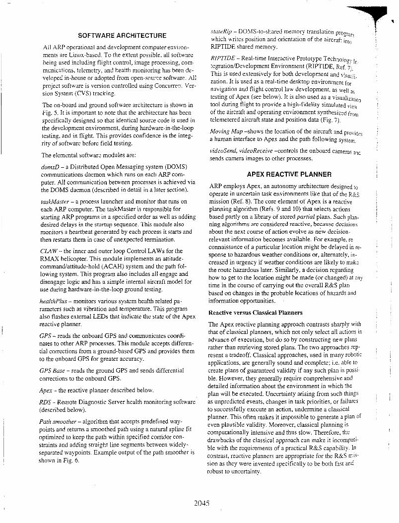
The on-board and ground software architecture is shown in Fig. 5. It is important to note that the architecture has been specifically designed so that identical source code is used in the development environment, during hardware-in-the-loop testing, and in flight. This provides confidence in the integ- rity of software before field testing.
The elemental software modules are:
clomsD - a Distributed Open Messaging system (DOMS) communications daemon which runs on each ARP com- puter. All communication between processes is achieved via the DOMS daemon (described in detail in a later section).
taskiMaster - a process launcher and monitor that runs on each ARP computer. The taskMaster is responsible for starting A W programs in a specified order as well as adding desired delays in the startup sequence. This module also monitors a heartbeat generated by each process it starts and then restarts them in case of unexpected termination.
CLAW- the inner and outer loop Control LAWS for the RMAX helicopter. This module implements an attitude- command/attitude-hold (ACAH) system and the path fol- lowing system. This program also includes all engage and disengage logic and has a simple internal aircraft model for use during hardware-in-the-loop ground testing.
healthPl14s - monitors various system health related pa- rameters such as vibration and temperature. This program also flashes external LEDs that indicate the state of the Apex reactive planner.
GPS - reads the onboard GPS and communicates coordi- nates to other ARP processes. This module accepts differen- tial corrections from a ground-based GPS and provides them to the onboard GPS for greater accuracy.
GPS Base - reads the ground GPS and sends differential corrections to the onboard GPS.
Apes - the reactive planner described below.
RDS - Remote Diagnostic Server health monitoring software (described below).
Path smoother - algorithm that accepts predefined way- points and returns a smoothed path using a natural spline fit optimized to keep the path within specified corridor con- straints and adding straight line segments between widely- separated waypoints. Example output of the path smoother is shown in Fig. 6.
RIPTIDE - Real-time Interactive Prototype Technology I n -
This is used extensively for both development and visuaii. zation. It is used as a real-time desktop environment for navigation and flight control law development, as well as testing of Apex (see below). It is also used as a visualiz;,t,,,, tool during flight to provide a high-fidelity simulated vie\\ of the aircraft and operating environment synthesized fro,, telemetered aircraft state and position data (Fig. 7).
Moving Map -shows the location of the aircraft and provides a human interface to Apex and the path following system,
videosend, videoReceive -controls the onboard cameras and sends camera images to other processes.
tegration/Development Environment (RIPTIDE, Ref. .-_ 7j,
APEX REACTIVE PLANNER
ARP employs Apex, an autonomy architecture designed to operate in uncertain task environments like that of the R&s mission (Ref. 8). The core element of Apex is a reactive planning algorithm (Refs. 9 and 10) that selects actions based partly on a library of storedpartial plans. Such plan- ning algorithms are considered reactive, because decisions about the next course of action evolve as new decision- relevant information becomes available. For example, re- connaissance of a particular location might be delayed in rc- sponse to hazardous weather conditions or, alternately, in- creased in urgency if weather conditions are likely to make the route hazardous later. Similarly, a decision regarding how to get to the location might be made (or changed) at any time in the course of carrying out the overall R&S plan based on changes in the probable locations of hazards and information opportunities.
Reactive versus Classical Planners
The Apex reactive planning approach contrasts sharply with that of classical planners, which not only select all actions in advance of execution, but do so by constructing new plans rather than retrieving stored plans. The two approaches rep- resent a tradeoff. Classical approaches, used in many robotic applications, are generally sound and complete; i.e. ab!e to create plans of guaranteed validity if any such plan is possi- ble. However, they generally require comprehensive and detailed information about the environment in which the plan will be executed. Uncertainty arising from such things as unpredicted events, changes in task priorities, or failures to successfully execute an action, undermine a classical planner. This often makes it impossible to generate a plan of even plausible validity. Moreover, classical planning is computationally intensive and thus slow. Therefore, the drawbacks of the classical approach can make it incompatl- ble with the requirements of a practical R&S capability. In contrast, reactive planners are appropriate for the R&S mis- sion as they were invented specifically to be both fast and robust to uncertainty.
I
2045
!
A 2036

r
Fig. 6. Moving map showing output of path smoother; way- points shown in red, constraint corridor shown in gray.
’ . .
Fig. 7. RMAX and Instrumentation trailer (top); real-time RIPTIDE view of same (bottom).
The Apex architecture was originally designed to emulate human behavior in domains such as air traffic control where correct behavior is partially defined by a set of standard op- erating procedures. Standardizing procedures in such do- mains has several advantages that are believed to be applica- ble to R&S missions. These include enhanced ability to co- operate with other agents and greater optimization of be- havior with respect to statistical regularities (risks and bene- fits) in the environment. Standardization also enhances pre- dictability, which in turn facilitates human-system interac- tion. Carried out concurrently or interleaved, procedures can interact and potentially conflict. The main challenge in de-
ciding action in such procedure-driven domains. cither for an autonomous agent or a real human operator, is thus to coor- dinate the execution of multiple procedures.
Procedure Definition Language (PDL)
Apex synthesizes a course of action mainly by linking to- gether elemental procedures expressed in Procedure Defini- tion Language (PDL), a notation developed specifically for the Apex reactive planner. A PDL procedure consists of at least an index clause and one or more step clauses. The index uniquely identifies the procedure and describes a class of goals for which the procedure is intended. Each s tep clause describes a subtask or auxiliary activity prescribed by the procedure. Steps are not necessarily carried out in the or- der listed or even in a sequence. Instead, they are assumed to be concurrently executable unless otherwise specified. If a fixed step ordering is desired, a wai t for clause is used to specify that the completion of one step is a precondition for the start of another.
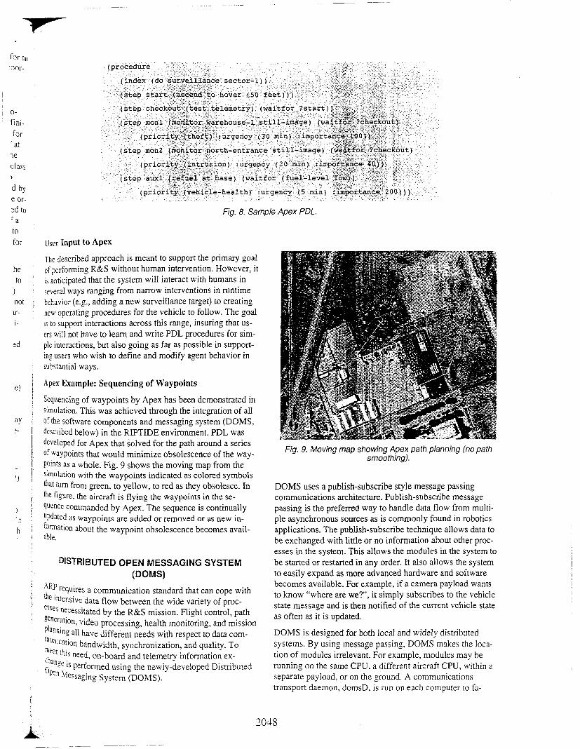
Fig. 8 shows a simple example of PDL. In the example, the step labeled checkout waits for the ascent to hover action to complete. The monitoring steps (labeled m o d and mon2) must wait for the checkout step to complete, but they are not otherwise constrained by the logic of the procedure. In par- ticular, no ordering constraints are imposed between moni- toring steps. If the procedure was allowed to control two UAVs, it would allow both monitoring steps to be executed in parallel. In this case, Apex would automatically detect that the two steps cannot be carried out concurrently and then attempt to resolve the conflict on the basis of prefer- ences (such as those specified in each step’s priority clause) and current situational information. Conflict resolution in such cases means deciding order and is thus inherently a scheduling problem. The set of conflicting tasks - there may be more than these two, since other procedures may be exe- cuting in parallel - are passed to Apex’s priority-based scheduler, which attempts to optimally sequence the tasks.
The example above illustrates two ways order can be deter- mined: I ) by explicit constraints in a stored procedure, or 2) by preference criteria (priorities) employed by scheduling mechanisms to resolve conflicts. This flexibility is at the heart of Apex’s integrated approach, allowing the system to draw on the capabilities of a reactive planner or on those of a scheduler as appropriate. This integration of scheduling with reactive planning has proven crucial for past applications of the Apex framework (Ref. 11). The main elements of the current approach are described in Refs. 8 and 12. In future work, the system’s scheduling capabilities will be extended to take advantage of a more sophisticated model of priority.
2047
i j
j
j ! 1
I
! I
!
I 0- fini- for at
ye
class
d by e or-
)
:d to - a
for IJser Input to Apex to
he to
1 not ir- i-
Fig. 8. Sample Apex PDL.
The described approach is meant to support the primary goal of performing R&S without human intervention. However, it is anticipated that the system will interact with humans in several ways ranging from narrow interventions in runtime behavior (e.g., adding a new surveillance target) to creating new operating procedures for the vehicle to follow. The goal is to support interactions across this range, insuring that us- ers will not have to learn and write PDL procedures for sim- plc interactions, but also going as far as possible in support- ing users who wish to define and modify agent behavior in substantial ways.
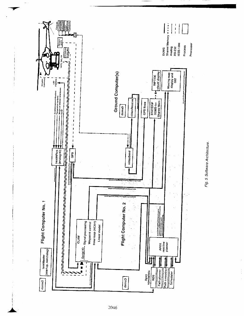
Apex Example: Sequencing of Waypoints
Sequencing of waypoints by Apex has been demonstrated in hulation. This was achieved through the integration of all of the software components and messaging system (DOMS, described below) in the RIPTIDE environment. PDL was developed for Apex that solved for the path around a series of wypoints that would minimize obsolescence of the way- Points as a whole. Fig. 9 shows the moving map from the Simulation with the waypoints indicated as colored symbols [hat turn from green, to yellow, to red as they obsolesce. In the figure, the aircraft is flying the waypoints in the se- quence commanded by Apex. The sequence is continually
as waypoints are added or removed or as new in- formation about the waypoint obsolescence becomes avail- able.
DISTRIBUTED OPEN MESSAGING SYSTEM (DOMS)
.i@ requires a communication standard that can cope with Ihe intensive data flow between the wide variety Of proc- esses necessitated by the R&S mission. Flight control, path
all have different needs with respect to data com- video processing, health monitoring, and mission
"'nication bandwidth, synchronization, and quality. To <?pa ''J [his need. on-board and telemetry information ex-
:an!e is performed using the newly-developed Distributed JPn -\lessaging System (DOMS).
Fig. 9. Moving map showing Apex path planning (no path smoothing).
DOMS uses a publish-subscribe style message passing communications architecture. Publish-subscribe message passing is the preferred way to handle data flow from multi- ple asynchronous sources as is commonly found in robotics applications. The publish-subscribe technique allows data to be exchanged with little or no information about other proc- esses in the system. This allows the modules in the system to be started or restarted in any order. It also allows the system to easily expand as more advanced hardware and software becomes available. For example. if a camera payload wants to know "where are we?', it simply subscribes to the vehicle state message and is then notified of the current vehicle state as often as it is updated.
DOMS is designed for both local and widely distribilted systems. By using message passing, DOMS makes the loca- tion of modules irrelevant. For example, modules may be running on the same CPU, a different aircraft CPU, within a separate payload, or on the ground. A communications transport daemon, domsD, is run on each computer to fa-
A 2048
cilitate the exchanse of information. The daemon is started before an); other modules and relays messages without hav- ing to decode or convert them. If the computers are con- nected by one or more unreliable communication links, the transport daemon can use multiple connections or multiple transmissions to insure that the message is delivered. The transport daemon can also compress messages to improve communications efficiency. All the issues of byte order and local structure field sizes are handled transparently by DOMS, allowing a heterogeneous mix of computers. In ad- dition, the binary messages can be efficiently logged for post processing.
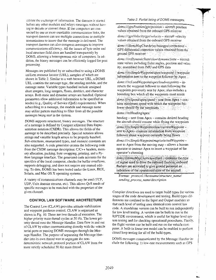
Table 2. Partial listing of DOMS messages
doms:fffgps Veloci~lgpsfvelocity - aircraft velocity values obtained from the onboard GPS receiver
doms:lllrcDynarnicStatelclaw/dynamicState - aircraft state values including Euler angles, position and veloc- ity; assembled from IMU and GPS data
Messages are published by or subscribed to using a DOMS uniform resource locator (URL), samples of which are shown in Table 2. Similar to a web browser URL, a DOMS URL contains the message type, the sending module, and the message name. Variable types handled include unsigned short integers, long integers, floats, doubles, and character arrays. Both static and dynamic arrays are handled. Optional parameters allow additional information to be specified as needed (e.g., Quality of Service (QoS) requirements). When subscribing to a message, the module and message name may utilize pattern matching to filter from all the possible messages being sent in the system.
DOMS supports structured, binary messages. The structure of a message is defined by Compact external Data Repre- sentation notation (CXDR). This allows the fields of the message to be described precisely. Special notation allows strings and variable length arrays to be properly handled. Sub-structures, enumerated types, and numeric constants are also supported. A code generator creates the following code from the CXDR message description: C/C++ headers, mem- ory allocation, packing, byte swapping, printing, and a Py- thon language interface. The generated code accounts for the specifics of the local computer, checks for buffer overflows, supports debugging, and does not require any manual edit- ing. To date, DOMS has been tested under the Linux, IRIX, Solaris, and Mac OS X operating systems.
A variety of communications channels may be used (TCP, UDP, Unix domain streams, etc). This allows QoS needs of specific messages to be matched with the properties of the given channel.
CONTROL LAW SOFTWARE ARCHITECTURE
The Control Law (CLAW) provides attitude stabilization and waypoint guidance control. CLAW is organized as shown in Fig. 10. There are two threads of execution. The higher priority main thread cycles at 50 Hz. The lower pri- ority thread runs the Message Handler. Data flow in and out of CLAW by either communicating directly with the vehicle serial ports or passing DOMS messages through the Mes- sage Handler. The purpose of separating the Message Han- dler into its own thread was to segregate the non- deterministic network protocol portion of CLAW from the more strictly scheduled 50 Hz main thread.
doms:lllrcLoadWaypointlapexlloadwaypoints - in- structs the waypoint follower to start following the waypoints previously sent by Apex; also includes a bounding box which all the waypoints must reside
doms:lllrcHeading/apex/ heading - sent from Apex - contains desired heading
dorns:lllrcSimple Waypointlmaplselected Waypoint - sent to Apex from the moving map - allows a human operator to instruct Apex to insert a waypoint of the oDerator’s choosinn
doms:/ff~omslC~sgChar/claw~ash - contains the type of signal used to drive the onboard flashers; onboard flashers are activated to give ground personal an indication of the operational state of the aircraft
Format: protoco1:llhostnamelstructure-name1 sending2rocess-nameldescription
Compiler directives are used to target build types for various stages of the code development and testing. Build types dif- ferences are confined to the Input and Output modules SO
that each level of testing uses identical core control law code. A standalone version can be built to run independently for low level testing. A version can be built to run in the RIPTIDE environment, which is useful for higher level SYS-
tern testing and for checking operational procedures. Finally, the flight version can be built and run on the vehicle com- puter. A built-in linear test model can be enabled to perform closed loop testing for all of the build types.
DOMS messages communicated by the Message Handler in- clude the following: 1) low-rate measurements such as GPS
3039
L

verted to attitude commands and altitude rate commands, which are sent to the Inner Loop Controller.
100 - i? s a ) - l O O
2-200 n
VI
-300
Fig. 10. Control law software architecture.
- flight
0-
- -
’ 1 “ ‘ l l I I I I I I l l 1 1
and Sonar Altitude, which are used to estimate the vehicle position and velocity; 2) operator commands to change CLAW variables; 3) telemetry data to the ground for display or recording; and, 4) guidance information from the planner In the form of waypoints.
The Input Module reads both the vehicle serial data and Processes any messages amving in the Message Handler. kh-rate attitude, attitude rate, and acceleration measure- ments critical to the attitude control are read directly from [he serial ports on each cycle of the control law. The low-
measurements are de-queued from the buffers filled by Ihe k s a p e Handler and distributed to various internal data “mctureS for use by the control law. Waypoints received by Ihe reactive planner are also de-queued and sent to the way- Point controller. Any ground commands are also processed here.
The Signal Processing module receives the sensor input and
?? estimates. This module also conditions the actuator ac- ‘ t \ ’ t t ~ and other vehicle health related data.
‘‘ ’ii3YPoint Controller takes the vehicle state estimates yd Ihe %‘point data from Apex and commands the Inner “p Controller. The inertial position and velocity are con-
[he necessary filtering to generate vehicle dynamic
The Inner Loop Controller feeds back the vehicle state in- formation to provide an ACAH control system to the Way- point Controller. The control law is designed using single input/single output design techniques on each axis of control using stick coordinates. The stick coordinates are then trans- formed into actuator commands, which are sent to the Out- put Module.
The Output Module sends all data through either the serial port or the Message Handler. Actuator commands from the Inner Loop Control are sent though the serial port. All other low rate data are sent through the Message Handler.
As mentioned previously, CLAW has a built-in Model which can be enabled for testing purposes. The model con- tains the key components that significantly affect the quality of the feedback including the identified vehicle model, non- linear kinematics, position and rate limited actuators, trans- port delay, sensor noise, and sensor quantization effects. The actuator commands are sent to the internal model as well as the vehicle actuators. The identified linear flight model was obtained from flight test data using established system iden- tification methods (Ref. 13). Fig. 11 shows a frequency re- sponse comparison of the identified pitch-rate-to- longitudinal-stick linear model to flight data. Enabling the model in the flight build allows for limited hardware-in-the- loop (HIL) closed loop testing on the ground. During HIL testing the sensor measurements are overwritten with the internal model values.
6- 40[ E 20
\
Frequency (radlsec)
Fig. 1 1. Comparison of identified pitch-rate-to-longitudinal- stick linear model frequency response to the same response
derived from flight data.

CLAW provides the ability to make variable changes durins execution. This enables the ground operator to adjust system gains during development and is also the mechanism by which the ground operator alters the state of the control law (e.g., opening or closing a particular feedback loop). Spe- cialized handshaking between the air and ground computers ensures that uncorrupted values withiz predefined jounds have been transmitted prior to being deposited. .i master re- set capability provides immediate ieconfiguraiion of all al- tered variables to pre-flisht initial states.
VEHICLE HEALTH MANAGEMENT
UAV reliability has proven to be a challenge due to their typically single-string flight control and sensor systems, and limited self awareness (Ref. 14). ARP will be addressing this area using a number of previously developed diagnostic tools. The real-time information produced by these tools will be used as input to the Apex reactive planner to aid in mis- sion planning.
A suite of commercial tools developed by Qualtech Systems, Inc. under NASA SBIR funding provides the modeling envi- ronment as well as the real-time diagnostic routines. The Remote Diagnostic Server (RDS, Ref. 15) provides the in- flight capability, while QSI's TEAMS (Testability Engi- neering and Maintenance System) tool is used to develop the system model initially used for testability analysis of the system design. The model is also used by RDS for online monitoring and diagnostics. These tools have been used in other recent NASA applications for Integrated Vehicle Health Management and are included in Honeywell's open architecture definition for IVHM, developed under the Space Launch Initiative, described in reference 16. This method will serve as a baseline for other diagnostic strategies that may be applied in ARP.
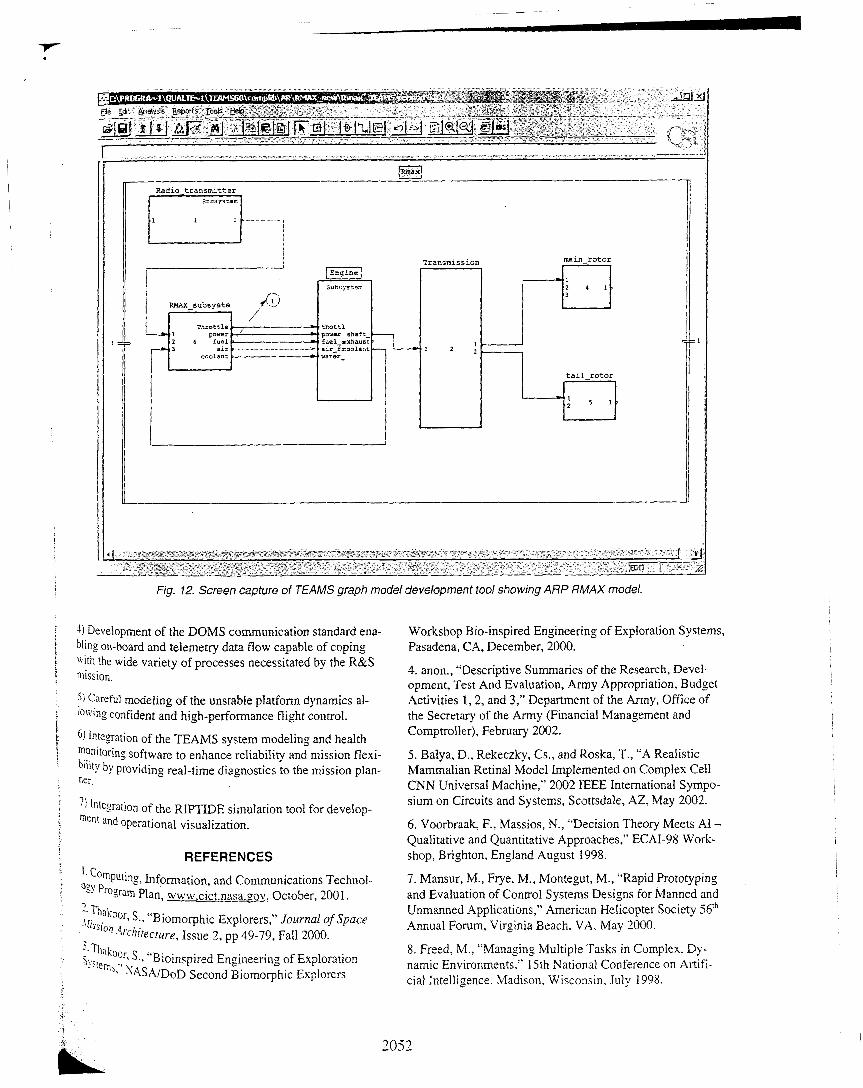
A model-based approach is being used to capture system in- formation for use in an intelligent diagnostic capability. A dependency model captures the system's configuration and observability. The multi-signal hierarchical modeling meth- odology uses a directed graph to capture the effects of fail- ures in terms of their propagation paths (Ref. 17). The graph model being developed for ARP is shown in Fig. 12. The initial model tracks the hardware and software configuration and provides documentation of the available sensors and how they are utilized.
Propagation algorithms convert the graph to a single global fault dictionary for a given mode and state of the system. This dictionary contains the basic information needed to in- terpret test results and diagnose failures during real-time monitoring. In the real-time implementation, the sensor data must be processed to determine features that can be mapped to the health status of the component or function being monitored. Once these features are defined, tests are devel- oped that compute the features and map them to various
failure modes or off-nominal behaviors. These tests will ba come part of the healthplus module which will then forua,< the test results to a higher-level reasoning module. The graph model is then used to analyze the propagation of the effects of off-nominal behavior to diagnose the root cause '. the problem.
Using RDS to Monitor Mode Switching
One of the first goals in developing the health management system, beyond simple threshold tests, is verification that the RMAX is ready to transition between flight modes. As sen. sors and flight parameters are monitored during a flight, the RDS will monitor system status and advise whether the syS. tem is ready for transitioning from remote control to corn. puter control, for example. In order to accomplish this goal. the dependency model will need to capture mode-specific behavior and be capable of discerning the correct operation of the components that are critical to the desired mode, function, and transition. During the initial development phase, the decision to transition will be made by the ground crew after manually reviewing a checklist in combination with system status checks that can be performed by CLAW. By incorporating the results of the monitoring capability that CLAW performs into the M A X dependency model, these two check-out steps can be performed automatically and the test results analyzed by RDS. RDS will then provide a deci- sion whether to proceed with the mode transition. Additional advanced capabilities are under investigation for incorpora- tion into an intelligent health management module that can provide status of available functions to the mission planner.
L' I [
' :
I
CONCLUDING REMARKS
Autonomous helicopter operations, be they for scientific or military purposes, pose many complex challenges. The Autonomous Rotorcraft Project (ARP) has developed an autonomous helicopter research platform to identify and ad- dress those weaknesses that impact autonomous mission ef- fectiveness the most. By demonstrating and evaluating po- tential solutions to these problems, ARP will provide much needed design guidance to future NASA and Army system development efforts. Key project efforts include:
1) Definition of an autonomous R&S mission that focuses development of a wide range of autonomous technologies and demonstrates the potential of future systems.
2) Integration of dual flight computers, precision GPS, ana- log temperature and vibration sensors, digital radio teleme- try, and four digital cameras (including a wide-baseline ste- reo pair) into a Yamaha RMAX helicopter resulting in a system that is highly capable yet flexible enough to permit easy integration of additional sensors or technologies.
3) Integration of the Apex reactive planner providing a new framework for rapid mission definition and execution that 1s
robust to uncertainty.
i j '
305 1
I
Radio t ransmit ter
RMRX-subsyste
Throttle power
Transmission
7 tail-rotor
Lfq I
Fig. 12. Screen capture of TEAMS graph model development tool showing ARP RMAX model.
4) Development of the DOMS communication standard ena- bling on-board and telemetry data flow capable of coping \iIth the wide variety of processes necessitated by the R&S mission.
5) Careful rnodellng of the unstable platform dynamics al- loLVlng confident and high-performance flight control.
6, integration of the TEAMS system modeling and health software to enhance reliability and mission flexi-
b”i[J’ by providing real-time diagnostics to the mission plan- ner
’I Integration of the RIPTIDE simulation tool for develop-
1 i
’
i i i
\ ‘lent and operational visualization.
REFERENCES
comPutlng, Information, and Communlcations Technol- “! Plan, www.cict.nasa.~o\l, October, 2001. ’ rhnkoor3 s , ‘‘Biomorphic Explorers,” Journal of space
?Ion qrchrtectul-e, Issue 2, pp 49-79, Fall 2000.
?!sieQs,.’ ‘ Ria'qor\ s “Bioinspired Engineering of Exploration xASA/D~D Second Biomorphic Explorers
Workshop Bio-inspired Engineering of Exploration Systems, Pasadena, CA, December, 2000.
4. anon., “Descriptive Summaries of the Research, Devel- opment, Test And Evaluation, Army Appropriation, Budget Activities 1, 2, and 3,” Department of the Army, Office of the Secretary of the Army (Financial Management and Comptroller), February 2002.
5. Balya, D., Rekeczky, Cs., and Roska, T., “A Realistic Mammalian Retinal Model Implemented on Complex Cell CNN Universal Machine,” 2002 IEEE International Sympo- sium on Circuits and Systems, Scottsdale, AZ, May 2002.
6. Voorbraak, F., Massios, N., “Decision Theory Meets AI - Qualitative and Quantitative Approaches,” ECAI-98 Work- shop, Brighton, England August 1998.
7. Mansur, M., Frye. M., Montegut, M., “Rapid Prototyping and Evaluation of Conuol Systems Designs for Manned and Unmanned Applications,” American Helicopter Society 56Ih Annual Forum, Virginia Beach. VA. May 2000.
8. Freed, M., “Managing Multiple ‘Tasks in Complex. Dy- namic Environments.” 15th National Conference on Artifi- cial Intelligence. Madison, Wisconsin, July 1998.
9. Firby, R., “Adaptive Execution in Complex Dynamic Worlds,” Ph.D. Thesis, Yale University Computer Science Department, Technical Report 672, January 1989.
10. Gat, E., “Integrating Planning and Reacting in Heteroge- neous Asynchronous Architecture for Controlling Real- World Mobile Robots,” 10th National Conference on Artifi- cial Intelligence, San Jose, CA. July 1992.
11. John, B., Vera, A., Matessa, M., Freed, M., and Rem- ington, R., “Automating CPM-GOMS,” CHI 2002 - Confer- ence on Human Factors in Computing Systems, Minneapo- lis, MN, April 2002.
12. Freed, M., “Reactive Prioritization,” 2nd NASA Interna- tional Workshop on Planning and Scheduling for Space, San Francisco, CA, 2000.
13. Tischler, M. and Cauffman, M., “Frequency-Response Method for Rotorcraft System Identification: Flight Appli- cations to BO- 105 Coupled RotorFuselage Dynamics,” Journal of the American Helicopter Society, Vol37, (3), July 1992.
14. Mount, M., “US. loses many military drones,” CNN News Service, January 2,2003.
15. Deb, S. and Ghoshal, S., “Remote Diagnosis Server Ar- chitecture’’, IEEE Autotest Conference, Valley Forge, PA, August 200 I .
16. Dixon, R., Hill, T., Kahle, W., Patterson-Hine, A., and Hayden, S., “Demonstration of an SLI Vehicle Health Man- agement System with In-Flight and Ground-Based Subsys- tem Interfaces,” 2003 IEEE Aerospace Conference, Big Sky, MT, March 2003.
17. Deb, S., et al, “Multi-Signal Flow Graphs: A novel Ap- proach for System Testability Analysis and Fault Diagno- sis,” IEEE Autotest Conference, Anaheim, CA, September 1994.
2053