ROTORCRAFT 9 - apps.dtic.mil
33
SUMMER 2010 ROTORCRAFT Survivability SUMMER 2010 STUDY ON ROTORCRAFT SURVIVABILITY V-22 INTEGRATED SURVIVABILITY DESIGN CH-53K HEAVY LIFT HELICOPTER 9 20 25 Published by the Joint Aircraft Survivability Program Office
Transcript of ROTORCRAFT 9 - apps.dtic.mil

SUMMER 2010
ROTORCRAFTSurvivability
SUMMER 2010
STUDY ON ROTORCRAFT SURVIVABILITY
V-22 INTEGRATED SURVIVABILITY DESIGN
CH-53K HEAVY LIFT HELICOPTER
92025
Published by the Joint Aircraft Survivability Program Office

Report Documentation Page Form ApprovedOMB No. 0704-0188
Public reporting burden for the collection of information is estimated to average 1 hour per response, including the time for reviewing instructions, searching existing data sources, gathering andmaintaining the data needed, and completing and reviewing the collection of information. Send comments regarding this burden estimate or any other aspect of this collection of information,including suggestions for reducing this burden, to Washington Headquarters Services, Directorate for Information Operations and Reports, 1215 Jefferson Davis Highway, Suite 1204, ArlingtonVA 22202-4302. Respondents should be aware that notwithstanding any other provision of law, no person shall be subject to a penalty for failing to comply with a collection of information if itdoes not display a currently valid OMB control number.
1. REPORT DATE 2010 2. REPORT TYPE
3. DATES COVERED 00-00-2010 to 00-00-2010
4. TITLE AND SUBTITLE Aircraft Survivability: Rotorcraft Survivability , Summer 2010
5a. CONTRACT NUMBER
5b. GRANT NUMBER
5c. PROGRAM ELEMENT NUMBER
6. AUTHOR(S) 5d. PROJECT NUMBER
5e. TASK NUMBER
5f. WORK UNIT NUMBER
7. PERFORMING ORGANIZATION NAME(S) AND ADDRESS(ES) JAS Program Office,200 12th Street South,Crystal Gateway #4, Suite 1103,Arlington,VA,22202
8. PERFORMING ORGANIZATIONREPORT NUMBER
9. SPONSORING/MONITORING AGENCY NAME(S) AND ADDRESS(ES) 10. SPONSOR/MONITOR’S ACRONYM(S)
11. SPONSOR/MONITOR’S REPORT NUMBER(S)
12. DISTRIBUTION/AVAILABILITY STATEMENT Approved for public release; distribution unlimited
13. SUPPLEMENTARY NOTES
14. ABSTRACT
15. SUBJECT TERMS
16. SECURITY CLASSIFICATION OF: 17. LIMITATION OF ABSTRACT Same as
Report (SAR)
18. NUMBEROF PAGES
32
19a. NAME OFRESPONSIBLE PERSON
a. REPORT unclassified
b. ABSTRACT unclassified
c. THIS PAGE unclassified
Standard Form 298 (Rev. 8-98) Prescribed by ANSI Std Z39-18

Table of ContentsA
ircr
aft S
urvi
vabi
lity
• Su
mm
er 2
010
Aircraft Survivability is published
three times a year by the Joint
Aircraft Survivability Program
Office (JASPO) chartered by the US
Army Aviation & Missile Command,
US Air Force Aeronautical Systems
Center and US Navy Naval Air
Systems Command.
JAS Program Office
200 12th Street South
Crystal Gateway #4, Suite 1103
Arlington, VA 22202
Views and comments are welcome
and may be addressed to the:
Editor
Dennis Lindell
Assistant Editor
Dale B. Atkinson
To order back issues of the
ASnewsletter, please visit
http://www.bahdayton.com/
surviac/inquiry.aspx.
On the cover: US Army soldiers with
Bravo Company, 1st Battalion, 214th
Aviation Regiment, examine their
CH-47 Chinook helicopter before an
aircraft turnover mission at Al Asad
Air Base, Iraq, on 1 Dec 2009.
DoD photo by Cpl. Joshua Murray,
US Marine Corps.
2
44News Notesby Dennis Lindell
50JCAT Cornerby CW5 Bobby Sebren, USA
6 Are We Doing Enough to Enhance the Survivability of Rotary Wing Aircraft?by Steven Mundt
With more than 130 helicopters losses reported in Iraq since the 2003 invasion and with over a third of these losses attributed to hostile fire such as anti-aircraft artillery and surface-to-air missiles, the need to improve helicopter survivability is both grave and well-known. What’s still missing is focus and urgency.
9 Study on Rotorcraft Survivabilityby Mark Couch and Dennis Lindell
In recent years, there has been an increasing concern regarding Department of Defense rotorcraft losses throughout Operation Enduring Freedom and Operation Iraqi Freedom (OEF/OIF). There is a perception that little progress has been made since the Vietnam conflict, especially when one compares the losses of rotary wing and fixed wing tactical aircraft (TACAIR). Accordingly, the Duncan Hunter National Defense Authorization Act (NDAA) for fiscal year 2009 (Section 1043) directed the Secretary of Defense and the Joint Chiefs of Staff to perform a study summarizing the loss rates and causal factors, and provide a prioritized list of candidate solutions for reducing rotorcraft losses.
14 LFT&E Oversight for UH-60M Black Hawk Programby Rick Seymour and Vincent Volpe
This article will present a synopsis of the UH-60M Live Fire Test and Evaluation (LFT&E) program overseen by the Director of Operational Test and Evaluation (DOT&E). This program, considered successful in most respects, was initiated in 1999 and entered into full rate production in July 2007. While not without some imperfections, this program followed an 8-year acquisition process that is typical for a successful Acquisition Category (ACAT) I program.
18 AH-1Z and UH-1Y: Designed for SurvivabilityBy Darrell Liardon and Michael Kouvarakos
Survivability is improved in both the AH-1Z and UH-1Y aircraft through enhanced ballistic hardening, signature reduction, and improved electronic countermeasures. Mission effectiveness is improved with the new cockpit and integrated avionics systems; increased weapons quantities and accuracy; and improved speed, range, and payload capabilities.

Air
craf
t Sur
viva
bili
ty •
Sum
mer
201
0
Mailing list additions, deletions,
changes, and calendar items may be
directed to:
SURVIAC Satellite Office
13200 Woodland Park Road
Suite 6047
Herndon, VA 20171
Promotional Director
Jerri Limer
Creative Director
Jerri Limer
Art Director
Michelle DePrenger
Technical Editor
Kali Wilson
Newsletter Design
Tammy Black
Illustrations, Cover Design, Layout
Michelle DePrenger
Brandi Samchisen
Sharon Yeager
Distribution Statement A:
Approved for public release; distribution
unlimited, as submitted under NAVAIR
Public Release Authorization 10-827.
3
20 V-22 Integrated Survivability Design Approachby Robert Laramee
The first V-22 Osprey production aircraft have successfully completed their Initial Operational Testing and Evaluations as well as their respective Initial Overseas Deployments for both the MV-22 and CV-22 variants. The V-22 tiltrotor is in use by the US Marine Corps (USMC) with the MV-22B and the US Special Operations Command (USSOCOM) via the CV-22. The V-22 replaces the 48-year-old CH-46 in the medium lift Marine inventory for assault support. The CV-22 is used for a range of USSOCOM missions including deep infiltration/exfiltration. Both V-22 aircraft have the same basic aircraft structure and engines with slightly different avionics and electronic-warfare equipment installations to meet their respective operational requirements. This discussion will review the survivability features of both aircraft.
23 Excellence in Survivability—Mark A. Couchby Dale Atkinson
The JASP is pleased to recognize Dr. Mark A. Couch for Excellence in Survivability. Mark is a Research Staff Member for the Institute for Defense Analyses (IDA) supporting rotary wing projects in operational and live fire test for the Director, Operational Test and Evaluation in the Office of the Secretary of Defense. Recently, he led the Data Collection Working Group in support of a Congressionally-mandated Study on Rotorcraft Survivability. Prior to joining IDA, he served in the Navy for 23 years as a helicopter pilot flying the MH-53E Sea Stallion. He served as military faculty at the Naval Postgraduate School from 2000–2003 where he first became intimately involved in the aircraft survivability discipline by carrying on the work of Dr. Robert E. Ball upon Bob’s retirement. In 2003, Mark earned his doctorate in Aeronautical and Astronautical Engineering from the Naval Postgraduate School with his dissertation in Rotary Wing Unsteady Aerodynamics.
25 CH-53K Heavy Lift Helicopter—A Survivability Focused Design by Nicholas Gerstner and Kathy Russell
The Sikorsky Aircraft Corporation (SAC) was awarded a System Development and Demonstration (SDD) contract in April of 2006 to design and build the next-generation heavy-lift rotorcraft platform for the US Marine Corps. The platform, designated as the CH-53K, is a ground-up re-design that incorporates the latest in helicopter technology, including new General Electric GE38-1B 7,500-hp engines, fly-by-wire flight controls, and composite airframe structures. The advanced capabilities of the drive and rotor systems will enable the aircraft to carry 27,000 lbs more than 110 nautical miles, which is three times the performance of its predecessor, the CH-53E. The CH-53K Preliminary Design Review (PDR) has been successfully completed in September 2008, and the Critical Design Review (CDR) is upcoming in Fall 2010.

Air
craf
t Sur
viva
bili
ty •
Sum
mer
201
0
4
News Notes
by Dennis Lindell
Sheppard Becomes ATC’s Test Technology DirectorAfter spending the last 10 years working as a staff specialist for the Director of Operational Test and Evaluation (DOT&E), Mr. Tracy Sheppard has been named the Director of Test Technology at the US Army’s Aberdeen Test Center (ATC), at Aberdeen Proving Ground, MD. The move became effective in April.
Mr. Sheppard, who was featured in the preceding issue of Aircraft Survivability for winning the 2009 Arthur Stein Award, says he is excited about the new position. “I think I am most excited,” he said, “about the opportunity to lead and mentor a workforce that is on the cutting edge of new technologies.” ATC’s Test Technology Directorate and its four divisions are primarily respon-sible for planning, conducting, analyzing, and reporting the results of developmen-tal, production, and other combat system tests, with a specific focus on the areas of development and access to state-of-the-art instrumentation.
This is not the first time Mr. Sheppard has worked for ATC, one of the Army’s premier test organizations. “It almost feels like going home,” he said. “This is where I worked my first job out of the Marine Corps. And it’s where I cut my teeth in testing and instrumentation.”
The move does come with some mixed emotions, however. Mr. Sheppard says he is proud of his DOT&E work, especially his efforts in body armor and helmet
issues, which directly affected the survivability of deployed US forces. He also admits he will miss his interaction with the other Services, as well as the individuals he worked closely with over the last decade (particularly the staff at the Institute for Defense Analyses).
“What I won’t miss,” he said, “is the 4–5-hour commute to and from the Pentagon each day.”
Mr. Sheppard has more than 20 years of experience in the research, development, test, and evaluation of military systems, particularly the LFT&E of major defense acquisition programs. Prior to his position with the DOT&E, he worked as an operations research analyst at the US Army Evaluation Center, as a test engineer and test director at ATC, and as an active duty Marine. In addition, he served as the Technical Director of the Washington office of the University of Texas at Austin’s Institute for Advanced Technologies.
Mr. Sheppard has associate’s and bachelor’s degrees in electrical engineer-ing from The Johns Hopkins University. He has lectured at the Defense Acquisition University and at the Naval Postgraduate School. His awards include the previously mentioned Stein Award, the NDIA Tester of the Year, the Secretary of Defense Medal for Exceptional Civilian Service, the Silver Award (Technical-Professional) from the Baltimore Federal Executive Board, and two Army Achievement Medals.
New BRAWLER v7.2 AvailableSURVIAC has begun distributing the newest classified and unclassified version of BRAWLER v7.2. Headquarters, United States Air Force/A9 (HQ USAF/A9) Directorate funds these programs and their upgrades with administrative support from the Joint Aircraft Survivability Program Office (JASPO). The new version of BRAWLER v7.2 model is an update from BRAWLER v7.1. This upgrade includes:
➤➤ Surface-to-Air Simulation Engagement Zone Generator
➤➤ Maneuver for Third-Party Targeting Illuminator/Guider Prior to Launch
➤➤ Fixed and Upgraded to Terrain Usage in BRAWLER
➤➤ Visualization/Graphics Upgrades associated with the JASPO digital radio frequency memory (DRFM) project; this includes upgraded displays and prints to grmain and asimain simulated distillation (SIMDIS)
➤➤ Improvements to Smart Jammer Modeling
➤➤ Fixes to Allow Compilation of BRAWLER with gfortran Compliers
➤➤ Integration of New ARGO Models ➤➤ Integration of Code from Lockheed Martin, Including Capture and Reduction-in-Lethality.
BRAWLER simulates air-to-air combat between multiple flights of aircraft in both the visual and beyond-visual-range (BVR) arenas. This simulation of flight-versus-flight air combat is considered to render realistic behaviors of military fighter pilots. BRAWLER incorporates value-driven and information oriented principles in its structure to provide a Monte Carlo, event-driven simulation of air combat between multiple flights of aircraft with real-world stochastic features. The user decides the pilot’s decision process including—
➤➤ Missions and Tactical Doctrines➤➤ Aggressiveness➤➤ Perceived Capability of the Enemy➤➤ Reaction Time➤➤ Quality of the Decisions Made
The supported platforms are Linux, SGI, and SUN.
You can obtain the new version of BRAWLER v7.2 from SURVIAC.
Tracy Sheppard
Air
craf
t Sur
viva
bili
ty •
Sum
mer
201
0
5
When I was asked to write the Joint Combat Assessment Team (JCAT) Corner for the Summer 2010 ASnewsletter focusing on “Rotorcraft Survivability,” I found myself uniquely positioned to take advantage of the opportunity. Now, in my 31st year of Army service, I have finally been presented with the chance to write an article for a professional magazine; my high school English teacher, Mrs. Maguire would be proud.
The definition of survivable is: sur definitiosәr'vaΙvәbәl [ser-vahy-vuh-buhl]
—adjective 1. able to be survived: Would an atomic
war be survivable? 2. capable of withstanding attack or
countermeasures: a bomber survivable against fighter planes.
Since we are in the military, any discussion on Rotorcraft Survivability would be incomplete without expanding the definition to include Combat Survivability. Every JCAT member begins their training with an introduc-tion to Dr. Robert E. Ball’s book The Fundamentals of Aircraft Combat Survivability Analysis and Design, Second Edition. In Dr. Ball’s book, Aircraft Combat Survivability is defined as “the capability of an aircraft to avoid or withstand a man-made hostile environment.” When something fails in our susceptibility chain, or as we say:
“The enemy gets a vote,” JCAT gets involved. Our job has many facets and includes—
➤➤ Inspecting weapon effects➤➤ Identifying the threat system used➤➤ Completing the combat damage assessment
➤➤ Out-briefing the command and the unit➤➤ Publishing the report to the Combat Damage Incident Reporting System (CDIRS)
➤➤ Advising the appropriate leadership and the Test & Evaluation Community if a potential deficiency is discovered during an assessment.
As a member of JCAT’s Army component, I can tell you that our team has been instrumental in at least 15 different material and/or Tactics, Techniques, and Procedures (TTP) solutions, and that solely involves Army aircraft. When you add up all of the JCAT findings across the Services, the number grows quickly, and all of these contribute to rotorcraft survivability.
Growing To Meet the NeedsAs mentioned in the spring 2010 newsletter’s JCAT Corner, we continue to support efforts in Iraq, while increasing our presence in Afghanistan. We have been busy training our new combat assessors, and are currently prepared to meet our “surge” requirements in Operation Enduring Freedom (OEF). This year will see JCAT assessors servicing all parts of Afghanistan.
JCAT Through the ServicesWhen we are not looking at combat damage, JCAT is often asked to brief our warfighters. In March, JCAT-Army’s CW4 James McDonough traveled to Bagram, Afghanistan to present a brief at the Regional Command East (RC-E) Air Threat Conference. This interaction benefits both the briefed units, as well as the next group of warfighters preparing to deploy. Lessons learned and TTPs being used are brought back to the continental US (CONUS) to be rolled into training for follow on units. During FY09, JCAT briefed approximately 4,900 deploying warfighters.
Over last few months JCAT’s Navy component has been working with the Countering Irregular Threats to Aviation Operations (CITAO) Task Group, which is sponsored by the J9 Concepts Branch of Joint Forces Command (JFCOM).
This group is assessing the best way to define and revise aviation TTPs to defeat emerging threats. JCAT is facilitating this effort by sharing the latest combat incident data from our current fight, as well as coordinating information sharing between JFCOM, Marine Aviation Weapons and Tactics Squadron 1 (MAWTS-1), United States Army Aviation Center of Excellence (USAACE), and the Naval Strike and Air Warfare Center at Fallon, Nevada.
JCAT’s Air Force component has responded to a request from Canadian Forces and is spearheading an effort to teach them about JCAT capabilities and training. Led by CMSgt Rick Hoover and Lt Col Norm White, a new training syllabus was constructed for the Canadians, and then ushered through approval agencies for foreign disclosure. Although this activity began in April 2009, it came to fruition with follow-on discussions in Canada in late 2009, and recently led to in-theater training by JCAT Officer in Charge CDR Fehrle. This coordinated effort to train an allied power in-situ is representative of a true joint effort.
JCAT’s Marine Corps component has been focused on training, recruiting, and positioning to expand the program. Currently staffed at 50%, they have solid prospects to reach 100% in the near-term. As a matter of fact, two new assessors are completing their training as this article goes to print. The Marines look forward to fielding more qualified JCAT assessors in future rotations. Finally, CW5 Chris Jordan, a mainstay of the JCAT Marine Corps program, will soon return from OEF. His deployment caps his 30-plus year career as a Marine; unfortunately for us, he will be retiring this summer. We wish him luck in all his future endeavors.
Wrap UpI know I speak for everyone on the JCAT team when I tell you that we are very proud of our role in Aircraft Survivability. We take our job very seriously and we work feverishly every day to try and put ourselves out of business!! To never lose another aircraft to enemy action is a dream we all wish for, but until that day, we will remain postured for the call. n
JCAT Corner by CW5 Bobby Sebren, USA
Air
craf
t Sur
viva
bili
ty •
Sum
mer
201
0
6
I think it is safe to say that everyone hopes that the Department of Defense (DoD), the Congress and the US defense industry goes to sleep at night asking,
“Have I done everything I could to protect those who serve to protect us?” The answer is a mixed bag. I am fortunate to have joined a group of dedicated men and women who represent this diverse body and volunteer their time and energy to help answer just this question, they are the members of the Combat Survivability Division of the National Defense Industrial Association (NDIA).
It is also safe to say that after almost nine years of sustained combat opera-tions and numerous reports from Commanders and Soldiers in the field, the importance of having rotary wing aviation forces is unparalleled in our history. This notion has also been supported by the work within the most recent Quadrennial Defense Review (QDR) that further amplifies the importance of aircraft in both Operation Iraqi Freedom (OIF) and Operation Enduring Freedom (OEF). Based on this and the paramount need to preserve our force, aircraft survivability is something we all need to think about. Whatever the answer is, it must be affordable, sustain-able, and it must protect the force better than we do today.
So, what is aircraft combat survivability? A commonly accepted definition is, “the capability to accomplish the mission while avoiding and/or withstanding a man-made hostile environment.” Given the burgeoning threat to US rotary-wing aircraft, particularly in asymmetric engagements and complex attacks, future US military helicopters must be more survivable and, indeed, designed and built with survivability as a key capability.
I am not the first to observe that we require helicopters that are difficult to detect, difficult to hit when detected, capable of continuing the mission after sustaining a hit, and crashworthy if shot down. It is critical for all these areas to be worked with a balanced and thoughtful approach that provides the best overall survivability capability possible (i.e., not neglecting hit tolerance for hit avoidance).
Reducing Probability of DetectionBecause you cannot hit what you cannot see, combat aircraft survivabil-ity directly relates to minimizing the probability of being detected (PD). A helicopter has five distinct signatures by which its presence can be detected: acoustic, radar, visual, electronic, and infrared (IR). Stealth measures focus on reducing these signatures to enemy detection. Given the Doppler Effect signature associated with helicopter blades, not to mention the sheer number of moving parts on these airframes, there are limits to the radar and visual signature reduction that can be brought to rotary wing aircraft via the incorpo-ration of energy-conductive coatings, use of broad-band radar absorption materials, and aerodynamic design.
The Army’s decision to cancel the RAH-66 Comanche evidenced that nominal gains in these areas are possible, but difficult to obtain and can be realized only at great or even unacceptable expense. Expense is not always tied to dollars, but also to weight, the impact on schedule due to integration and non-recurring engineering; and finally the reliability/maintainability of the systems.
While infrared suppressors vent hot gasses into the rotor system or blower fans introduce ambient air into the engine housing hold the potential to
reduce a helicopter’s traditionally large thermal signature, the necessary configuration/location of helicopter engines has generally placed strict limits on achievable IR emission reduction in rotary wing aircraft. However, this does not account for the other locations that produce heat signatures, such as weapons and gearboxes.
While reducing main rotor speed, improvements in blade tip design, and integration of no-tail rotor (NOTAR) designs can reduce inherent acoustic signatures, there are likewise physical limitations to reducing noise associated with main rotors, tail rotors, and engines.
Some key advances have been realized in electronic signature reduction on fixed-and rotary-wing aircraft via the incorporation of non-emitting, on-board passive systems. However, the bottom line is that until a “Klingon cloaking device” appears—and that does not appear to be imminent—vertical lift designers and operators will have to accept that rotary-wing aircraft will have significant signatures, will be detectable, and that efforts to enhance survivability will need to focus on approaches to survivability beyond just not being seen.
Given the challenges inherent to building undetectable helicopters, cost-effective survivability enhancement for rotary-wing aviation must necessarily focus on reducing the probability of a hit (P
H) given helicopter detection and reducing the probability of kill (PK) given a hit. The key to success is the balance between detection and avoidance. A modest/affordable reduction in signature improves the Aircraft Survivability Equipment (ASE) capability and afford-ability. Vulnerability Reduction (reducing PK) comes into play when
Are We Doing Enough to Enhance the Survivability of Rotary Wing Aircraft?
by Stephen Mundt
With more than 130 helicopters losses reported in Iraq since the 2003 invasion and with over a third of these losses attributed to hostile fire such as anti-aircraft artillery and surface-to-air missiles, the need to improve helicopter survivability is both grave and well-known. What’s still missing is focus and urgency.

Air
craf
t Sur
viva
bili
ty •
Sum
mer
201
0
7
countermeasures are not successful (they are never 100%) and when the unex-pected occurs (i.e., the enemy brings a new weapon or tactic to the battlefield).
Reducing Probability of Hit (PH) Given DetectionReducing the probability of a helicopter being acquired, engaged, and hit by enemy fire given detection is perhaps the area where DoD focus can yield the greatest and most efficient return on investment. Reduction in enemy PH of rotary-wing aircraft is achievable through the employment of an integrated early warning system tailored to sense specific threat systems and the consequent use of countermeasures (radar or infrared jammers, and chaff or decoy flares) that cause sufficient threat system degradation to keep the helicopter from being successfully engaged by enemy weapons.
Whereas today’s rotary-wing ASE can identify a threat, tomorrow’s systems should be able to classify it, deploy the appropriate countermeasures, and advise on—or even automate—exact evasive maneuvers. This is a systems approach to solving the hit issue. The future will require that we address the key enabling capabilities by integrating ASE on-board and networking ASE off-board. Ultimately, it is about knowing where you are and where the enemy is so that you can feed the Common Operating Picture (COP) and get real time (or near real time) updates that allow you to operate inside the enemy’s decision cycle and not let him operate in and disrupt your decision cycle. When the enemy detects a platform, they must then acquire and maintain lock on the target to achieve a hit. We must be able to determine if we are being acquired and at what stage we are in the enemy’s kill chain. We can prevent or break lock by changing our flight profile, if the projectile is in flight we can decoy it with chaff or flares, or we can defeat the seeker via jamming. We can also break lock by geo-locating the shooter’s position and making that location untenable with return fire. Knowing the shooter’s location and providing the aircrew verbal/visual cues on evasive maneuvers masking the aircraft from the enemy, enhance the whole process. If these measures fail, we must to be able to withstand the hit and bring the crew and aircraft back to be repaired.
The US Army and other Military Services have heavily invested in infrared counter-measure (IRCM) systems development for
more than a decade, including the Large Infrared Countermeasures (LIRCM), Directional Infrared Countermeasures (DIRCM) and Advanced Threat Infrared Countermeasure (ATIRCM) programs. However, these systems have been highly unreliable, excessively costly, and too large and heavy for broad application to rotary wing fleets. Although the Army’s current Common Infrared Countermeasures (CIRCM) program appears to have the right focus, this capability is long overdue.
And while today’s systems—including the Common Missile Warning System/Improved Countermeasure Dispenser (CMWS/ICD)—provide admirable capability against IR threats, tomor-row’s warning receiver systems must have equal capabilities to detect, identify, and counter laser threats such as range finders, designators, and beam-riding missiles, RF threats, acoustic threats and profile recognition threats. We have been working on the IR threats for over 15 years and have not solved the problem, if we are to keep pace with the changing capabilities of technology and the defeat the growing threats of tomorrow we must do better.
Another challenge is not just from the human enemy but from the environmen-tal threat as well. With many helicopter missions now carried out during periods of low visibility or at night, challenges associated with spatial orientation have come to the fore. Our operators have learned that few of our operational missions are “hard stand to hard stand,” but are more often dirt-to-dirt, making brownouts and whiteouts common challenges. It is unacceptable that we do not have a visual reference system allowing our pilots to land safely.
Related to this environmental threat is another area where technology can and should be harnessed by DoD to enhance aircraft survivability. Enhancing obstacle warning and avoidance with respect to natural and man-made obstacles such as wire avoidance systems is a continued imperative. While it is well recognized that advances in helicopter speed and agility (at both high and low speeds) can enhance helicopter survivability, particularly once a system is engaged, DoD has been slow to invest in the compound and/or vectored thrust helicopter technology development
that might provide for the leap-ahead speed and agility than might otherwise be achieved.
Reducing Probability of Kill (PK) Given a HitDespite the success of efforts to reduce PD and PH, more can and should be done to enhance helicopter survivability—or tolerance to fire—given a hit. At the core of meeting this objective are design efforts to enhance ballistic tolerances of rotary wing aircraft via the hardening, duplication/redundancy and dispersion of critical flight components throughout the helicopter.
While helicopters are intrinsically vulnerable, the smart use of advanced materials and technologies in their design and construction can yield enhanced performance and protection at less weight. For example, lightweight, composite, epoxy-resin materials can be used to develop rotor systems and drive shafts with improved performance and better ballistic damage tolerance.
Survivability enhancements are also being realized as part of system fleet upgrades as lessons learned from operations are implemented. Based on damage sustained by US forces in Iraq and Afghanistan, for example, Army’s Aviation Applied Technology Directorate (AATD) successfully implemented three research programs—SIMS, BPS/AATD MFS, and SAPS—each targeted against rifle-caliber machine-guns.
➤➤ The Structural Integrity Monitoring System (SIMS) tracks structural stresses on aircraft and reports failures before they happen—some thing that the Army has termed a pressurized fault-detection system in rotor blades, writ large.
➤➤ The Ballistic Protection System (BPS) provides cargo and utility helicopters a common, “double-duty” armored structural floor, replacing having both the structural flooring and the armor appliqué, thus saving weight and increasing range and payload.
➤➤ The Spaced-Armor Protection System (SAPS) uses a standoff plate within the helicopter to destabilize, tumble, and breakup an incoming projectile, thus significantly reducing its penetrating power before catching it with an internal armor plate. It also reduces the overall system weight for equal or greater levels of protection.
Continued on page 24

Air
craf
t Sur
viva
bili
ty •
Sum
mer
201
0
9
In recent years, there has been an increasing concern regarding Department of Defense rotorcraft losses throughout Operation Enduring Freedom and Operation Iraqi Freedom (OEF/OIF). There is a perception that little progress has been made since the Vietnam conflict, especially when one compares the losses of rotary wing and fixed wing tactical aircraft (TACAIR). Accordingly, the Duncan Hunter National Defense Authorization Act (NDAA) for fiscal year 2009 (Section 1043) directed the Secretary of Defense and the Joint Chiefs of Staff to perform a study summarizing the loss rates and causal factors, and provide a prioritized list of candidate solutions for reducing rotorcraft losses.
Under the auspices of the Offices of the Under Secretary of Defense for Acquisition, Technology & Logistics (OUSD [AT&L]) led Future Vertical Lift Initiative, the Joint Aircraft Survivability Program Office (JASPO) and the Director of Operational Test and Evaluation (DOT&E), with support from the Institute for Defense Analyses, led a multi-disciplinary team of the Office of the Secretary of Defense (OSD) and Service subject matter experts on rotorcraft safety and survivability to complete the study and report the results to the Joint Chiefs of Staff, OSD, and Congress. The study team focused on losses occurring during the OEF/OIF timeframe to understand the loss causes and to provide solutions relevant to current and future DoD vertical lift aircraft. The analysis was supported by a comprehensive review and in-depth analysis of combat damage reports beginning with Vietnam and by a review of Class A mishap reports from 1985–2009. [1]
Results of this study have been briefed extensively within the DoD and to each of the Services.
Rotorcraft Loss DataAirframe losses and fatalities were classified in three categories: Combat Hostile Action, Combat Non-Hostile, and Non-Combat. This study places fatalities and airframe losses in two distinct categories to ensure that candidate solutions address both reduction in airframe losses and reduc-tion in fatalities. Table 1 gives a descrip-tion of each category and states the corresponding goal that Congress articulated in the NDAA. Causal factors for Combat Hostile Action losses/fatalities are identified by threat weapon and aircraft subsystems affected. Causal factors for mishaps are identified by phase of flight and whether they are human factors or non-human factors mishaps. Recommendations are made for further reducing losses to achieve the respective goals.
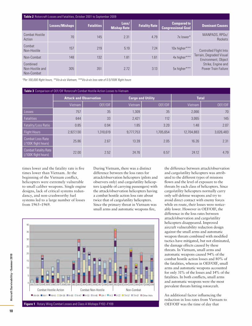
During OEF/OIF, there were 375 rotorcraft losses with 496 fatalities from October 2001 to September 2009. Table 2 summarizes the combat hostile action losses, Class A mishaps, fatalities, and
rates by category. Class A mishaps, which include both non-hostile and non-combat events, accounted for 305 losses, or 81% of all 375 losses, and combat losses (i.e., aircraft shootdowns) accounted for the remaining 19%. Losses in a combat theater, which includes 70 combat hostile action events and 157 non-hostile events, made up 61% of all losses and 73% of all fatalities. Loss and fatality rates in combat theaters were also higher and are attributed to the higher operational tempo that includes increased numbers of passengers on cargo and utility helicopter missions, acceptance of more operational risk on many missions, and routine exposure to combat threats. Figure 1 shows the losses and mishaps by aircraft type and year. Caution should be used when interpreting data from this figure. While this figure shows the quantity of each rotorcraft lost in each category, comparisons should be made based on loss rates. The purpose of this chart was to show only the aggregate of all the losses across the fiscal years.
Combat Hostile Action LossesHelicopter combat hostile action losses in OEF/OIF are significantly less than in Vietnam. Table 3 shows that the total loss rate for all rotorcraft types is seven
Study on Rotorcraft Survivability
by Mark Couch and Dennis Lindell
“[T]here’s no doubt that this is the most difficult terrain that I’ve ever seen in 33 years, to actually walk across, operate in or to fight in, or, for that matter, to actually help the people in. Helicopters are just more than part and parcel of what we do each and every day. They are critical to almost every operation that we execute here in Afghanistan.”
—Maj. Gen. Jeffrey Schloesser, Commander of the Combined Joint Task Force–101 in Afghanistan Inside the Army, June 8, 2009
Table 1 Loss Category Definitions and Goals
Loss Category Definition Congressional Goal
Combat Hostile ActionCombat losses (where hostile fire was involved involving loss of airframe or a fatality)
Loss rate ≤ Vietnam
Combat Non-HostileClass A mishaps in combat zones (where no hostile fire was involved)
Mishap loss rate < 0.5 mishaps/100K flight hours
Non-Combat Class A mishaps in non-combat zonesMishap loss rate < 0.5 mishaps/100K flight hours
Air
craf
t Sur
viva
bili
ty •
Sum
mer
201
0
10
times lower and the fatality rate is five times lower than Vietnam. At the beginning of the Vietnam conflict, helicopters were extremely vulnerable to small caliber weapons. Single engine designs, lack of critical systems redun-dancy, and non-crashworthy fuel systems led to a large number of losses from 1965–1969.
During Vietnam, there was a distinct difference between the loss rates for attack/observation helicopters (pilots and observers only) and cargo/utility helicop-ters (capable of carrying passengers) with the attack/observation helicopters having a combat hostile action loss rate about twice that of cargo/utility helicopters. Since the primary threat in Vietnam was small arms and automatic weapons fire,
the difference between attack/observation and cargo/utility helicopters was attrib-uted to the different types of missions flown and the level of exposure to the threats by each class of helicopters. Since cargo/utility helicopters normally carry only self-defense weapons and try to avoid direct contact with enemy forces while en route, their losses were notice-ably lower. However in OEF/OIF, the difference in the loss rates between attack/observation and cargo/utility helicopters disappeared. Improved aircraft vulnerability reduction design against the small arms and automatic weapon threats combined with modified tactics have mitigated, but not eliminated, the damage effects caused by these threats. In Vietnam, small arms and automatic weapons caused 94% of the combat hostile action losses and 80% of the fatalities, whereas in OEF/OIF, small arms and automatic weapons accounted for only 31% of the losses and 14% of the fatalities. In both conflicts, small arms and automatic weapons were the most prevalent threats hitting rotorcraft.
An additional factor influencing the reduction in loss rates from Vietnam to OEF/OIF was the time of day that
Combat Hostile Action Combat Non-Hostile Non-Combat
2002 2003 2004 2005 2006 2007 2008 2009
30
25
20
15
10
5
0
35
40
2002 2003 2004 2005 2006 2007 2008 2009 2002 2003 2004 2005 2006 2007 2008 2009
Other HeloTH-67TH-57V-22H-3UH-1H-46H-53H-47H-60OH-58AH-6AH-1AH-64
Figure 1 Rotary Wing Combat Losses and Class A Mishaps FY02–FY09
Table 2 Rotorcraft Losses and Fatalities, October 2001 to September 2009
Losses/Mishaps FatalitiesLoss/
Mishap RateFatality Rate
Compared to Congressional Goal
Dominant Causes
Combat Hostile Action
70 145 2.31 4.79 7x lower*MANPADS, RPGs/
Rockets
Combat Non-Hostile
157 219 5.19 7.24 10x higher***Controlled Flight Into
Terrain, Degraded Visual Environment, Object
Strike, Engine and Power Train Failure
Non-Combat 148 132 1.81 1.61 4x higher***
Combined Non-Hostile and Non-Combat
305 351 2.72 3.13 5x higher***
*Per 100,000 flight hours, **Vis-à-vis Vietnam, ***Vis-à-vis loss rate of 0.5/100K flight hours
Table 3 Comparison of OEF/OIF Rotorcraft Combat Hostile Action Losses to Vietnam
Attack and Observation Cargo and Utility Total
Vietnam OEF/OIF Vietnam OEF/OIF Vietnam OEF/OIF
Losses 757 35 1,309 35 2,066 70
Fatalities 644 33 2,421 112 3,065 145
Fatality/Loss Ratio 0.85 0.94 1.85 3.20 1.48 2.07
Flight Hours 2,927,130 1,310,619 9,777,753 1,705,654 12,704,883 3,026,483
Combat Loss Rate (/100K flight hours)
25.86 2.67 13.39 2.05 16.26 2.31
Combat Fatality Rate (/100K flight hours)
22.00 2.52 24.76 6.57 24.12 4.79

Air
craf
t Sur
viva
bili
ty •
Sum
mer
201
0
11
combat flights were flown. In Vietnam, helicopters were not equipped with night vision devices, and the percentage of night flights was small. Thus, nearly all of the Vietnam losses occurred in daylight or twilight hours when the enemy may have had an opportunity to visually acquire the aircraft before firing his weapon. In OEF/OIF, most helicop-ters were equipped with night vision devices, and night flights were routine. These more frequent night flights limited the enemy’s ability to visually acquire the helicopter before engaging it. Validation of this point is seen in the fact that 75% of the combat hostile action losses in OEF/OIF occurred during daylight or twilight hours, which shows that visual identification is one of the primary methods for the enemy to acquire rotary wing aircraft.
Fatality rates for both conflicts are higher for cargo/utility helicopters primarily because of the higher number of occupants on each flight. In Vietnam, the fatality to loss ratio for cargo/utility helicopters was 1.85, but in OEF/OIF, the ratio increased to 3.2. The reason for this increase is the extensive vulnerability reduction programs on helicopters designed since Vietnam reducing the number of losses due to smaller caliber weapons. Losses due to smaller caliber weapons tend to cause fewer fatalities while more lethal threats such as man-portable air defense systems (MANPADS), rocket propelled grenades (RPGs), and rockets caused far more fatalities per loss.
Lastly, there were no reported rotary wing losses in OEF/OIF due to radar guided weapons. Although this threat was not prevalent in OEF/OIF, it should not be dismissed when designing against future threat projections.
Combat Non-Hostile and Non-Combat LossesTable 2 shows that the combat non-hostile mishap rate was ten times higher and the non-combat loss rate was four times higher than the DoD and Congressional goal of 0.5 mishaps per 100,000 flight hours. When all mishaps are combined (both combat non-hostile and non-combat), the mishap loss rate was 2.72 losses per 100,000 flight hours, slightly exceeding the loss rate due to combat hostile action of 2.31. Figure 2 shows the number by year of rotary wing Class A mishaps, destroyed aircraft, and fatalities, using the bars and the left vertical axis. The significant increase in
the number of fatalities compared to the number of Class A mishaps is directly related to the higher operational tempo associated with combat operations in Iraq. The higher operational tempo includes an increased numbers of passengers on cargo and utility helicopter missions and an acceptance of more operational risk on many missions.
To get a better feel for how the rotary wing mishap rates compare to fixed wing and tactical air (TACAIR), Figure 2 also shows the Class A mishap rates, using the lines and the right vertical axis. The figure shows rates for all aircraft (orange line), all fixed wing (maroon line), TACAIR (red line), and rotary wing (light blue line) compared to the DoD goal (green line) of 0.5 mishaps per 100,000 flight hours. Although the mishap rates for all fixed wing are lower than all rotary wing, the TACAIR mishap rates are about equal to rotary wing. The reason for this difference is that the TACAIR and rotary wing have about the same number of mishaps and flight hours each year while the larger cargo/bomber aircraft (making up the rest of fixed wing) have many fewer mishaps and about twice the flight hours as both TACAIR and rotary wing. Use of the fiscal year reporting method used by all the Services sometimes creates an artificial binning of data that may produce a graphical anomaly. To smooth out possible anomalies created by the binning across fiscal years, a three-year running average for all rotary wing (dark blue line) is also plotted in Figure 2 to show that generally from FY04 to FY08, the mishap rate is trending downward. The downward trending of the three-year running average from
FY04 to FY09 for Class A mishaps are due to OIF infrastructure maturation; combat tactics, techniques, and proce-dures (TTPs) maturation; and opera-tional risk reduction brought on via a drawdown in combat type of operations in FY08 and FY09.
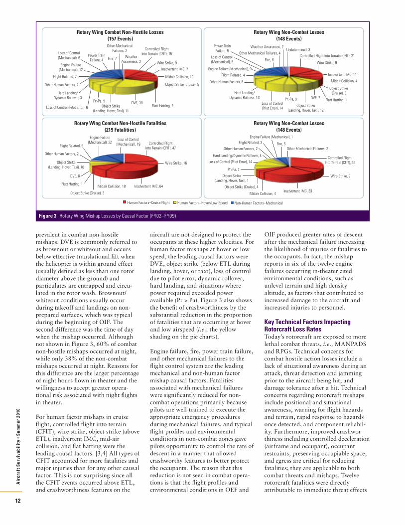
In the review of the mishap causal factors, two important trends were identified in mishap fatality data—1) the velocity at which the event occurs and 2) whether it is a human factors or non-human factors mishap. Figure 3 shows the distribution of causal factors for combat non-hostile and non-combat mishap losses and fatalities. The red and yellow slices of the pie charts indicate human factors mishaps. Human factor mishaps are further subcategorized by velocity to account for similar flight profiles. The red slices are human factor mishaps occurring in cruise flight while the yellow slices are human factor mishaps occurring in hover or low speed below effective translational lift (ETL). The blue slices indicate non-human factor mishaps and include mechanical failures such as engine failures, drive train failures, and aircraft fires. [2] The purple slices indicate flight related, improperly forecasted weather, and undetermined mishaps that did not fit well into one of the other categories. Human factor mishaps (red and yellow slices) ac-counted for 78% of airframe losses and 84% of the fatalities.
The primary causal factors for combat non-hostile and non-combat mishaps were very similar with two exceptions. Mishaps due to degraded visual environment (DVE) were more
Des
troy
ed A
ircr
aft o
r Fat
aliti
es
Rate
per
100
,000
Flig
ht H
ours
FY02 FY03 FY04 FY05 FY06 FY07 FY08 FY09
120
60
0
100
40
80
20
5.00
3.50
2.00
4.50
3.00
4.00
2.50
1.50
0.00
1.00
0.50
RW Class A Mishaps RW Destroyed A/C RW Facilities All Aviation Mishap Rate All FW Mishap Rate
TACAIR Mishap Rate RW Mishap Rate RW Mishap Rate (3-yr Avg) DoD Goal
Figure 2 DoD Aircraft Class A Mishaps FY02–FY09.
Air
craf
t Sur
viva
bili
ty •
Sum
mer
201
0
12
prevalent in combat non-hostile mishaps. DVE is commonly referred to as brownout or whiteout and occurs below effective translational lift when the helicopter is within ground effect (usually defined as less than one rotor diameter above the ground) and particulates are entrapped and circu-lated in the rotor wash. Brownout/whiteout conditions usually occur during takeoff and landings on non-prepared surfaces, which was typical during the beginning of OIF. The second difference was the time of day when the mishap occurred. Although not shown in Figure 3, 60% of combat non-hostile mishaps occurred at night, while only 38% of the non-combat mishaps occurred at night. Reasons for this difference are the larger percentage of night hours flown in theater and the willingness to accept greater opera-tional risk associated with night flights in theater.
For human factor mishaps in cruise flight, controlled flight into terrain (CFIT), wire strike, object strike (above ETL), inadvertent IMC, mid-air collision, and flat hatting were the leading causal factors. [3,4] All types of CFIT accounted for more fatalities and major injuries than for any other causal factor. This is not surprising since all the CFIT events occurred above ETL, and crashworthiness features on the
aircraft are not designed to protect the occupants at these higher velocities. For human factor mishaps at hover or low speed, the leading causal factors were DVE, object strike (below ETL during landing, hover, or taxi), loss of control due to pilot error, dynamic rollover, hard landing, and situations where power required exceeded power available (Pr > Pa). Figure 3 also shows the benefit of crashworthiness by the substantial reduction in the proportion of fatalities that are occurring at hover and low airspeed (i.e., the yellow shading on the pie charts).
Engine failure, fire, power train failure, and other mechanical failures to the flight control system are the leading mechanical and non-human factor mishap causal factors. Fatalities associated with mechanical failures were significantly reduced for non-combat operations primarily because pilots are well-trained to execute the appropriate emergency procedures during mechanical failures, and typical flight profiles and environmental conditions in non-combat zones gave pilots opportunity to control the rate of descent in a manner that allowed crashworthy features to better protect the occupants. The reason that this reduction is not seen in combat opera-tions is that the flight profiles and environmental conditions in OEF and
OIF produced greater rates of descent after the mechanical failure increasing the likelihood of injuries or fatalities to the occupants. In fact, the mishap reports in six of the twelve engine failures occurring in-theater cited environmental conditions, such as unlevel terrain and high density altitude, as factors that contributed to increased damage to the aircraft and increased injuries to personnel.
Key Technical Factors Impacting Rotorcraft Loss RatesToday’s rotorcraft are exposed to more lethal combat threats, i.e., MANPADS and RPGs. Technical concerns for combat hostile action losses include a lack of situational awareness during an attack, threat detection and jamming prior to the aircraft being hit, and damage tolerance after a hit. Technical concerns regarding rotorcraft mishaps include positional and situational awareness, warning for flight hazards and terrain, rapid response to hazards once detected, and component reliabil-ity. Furthermore, improved crashwor-thiness including controlled deceleration (airframe and occupant), occupant restraints, preserving occupiable space, and egress are critical for reducing fatalities; they are applicable to both combat threats and mishaps. Twelve rotorcraft fatalities were directly attributable to immediate threat effects
Full-up/Full-scale System Level (FUSL) Testing (dynamic)
Subsystem Level Testing(static and dynamic)
Component Level Testing(mostly static)
Development Testing(Continues thru FUSL)
FUSL testing builds on earlier testing to refine shotlines and threats reducing more costly testing on full-up assets.
LFT&E program conducted 144 shots; including 40 dynamic tests LFT Evaluation also included previous JLF tests (>400 tests), and combat data from Grenada,
Turkey, Somalia, OIF/OEF Tested both API and HEI projectiles (7.62mm through 23mm)
Testing early allows design changes and fixes to
be implemented before full-rate production
Decreasing number of tests
System IntegrationLaboratory Testing
Existing Test and Combat Data
Rotary Wing Combat Non-Hostile Losses(157 Events)
Fire, 7
Other MechanicalFailures, 2 Weather
Awareness, 2
WeatherAwareness, 2
Other MechanicalFailures, 2
Fire, 7Power Train
Failure, 4Wire Strike, 9
Inadvertent IMC, 7
Midair Collision, 10
Object Strike (Cruise), 5
Flatt Hatting, 2DVE, 38
Object Strike(Landing, Hover, Taxi), 11
Pr>Pa, 9
Loss of Control (Pilot Error), 6
Hard Landing/Dynamic Rollover, 3
Other Human Factors, 2
Flight Related, 7
Engine Failure(Mechanical), 12
Loss of Control(Mechanical), 6
Controlled FlightInto Terrain (CFIT), 15
Rotary Wing Combat Non-Hostile Fatalities(219 Fatalities)
Loss of Control(Mechanical), 19
Engine Failure(Mechanical), 22 Controlled Flight
Into Terrain (CFIT), 47
Wire Strike, 16
Inadvertent IMC, 64Midair Collision, 18
Object Strike (Cruise), 3
Flatt Hatting, 1
DVE, 8
Object Strike(Landing, Hover, Taxi), 10
Other Human Factors, 2
Flight Related, 6
Rotary Wing Non-Combat Losses(148 Events)
Controlled Flight Into Terrain (CFIT), 21
Wire Strike, 9
Inadvertent IMC, 11
Midair Collision, 4
Object Strike (Cruise), 3
Flatt Hatting, 1DVE, 7
Object Strike(Landing, Hover, Taxi), 12
Pr>Pa, 9Loss of Control(Pilot Error), 14
Hard Landing/Dynamic Rollover, 13
Other Human Factors, 6
Flight Related, 4
Engine Failure (Mechanical), 9
Loss of Control (Mechanical), 5
Power TrainFailure, 5
Fire, 6
Other Mechanical Failures, 4
Weather Awareness, 2Undetermined, 3
Rotary Wing Non-Combat Losses(148 Events)
Wire Strike, 9
Inadvertent IMC, 33Midair Collision, 4
Object Strike (Cruise), 4
Object Strike(Landing, Hover, Taxi), 1
Pr>Pa, 7
Loss of Control (Pilot Error), 14
Hard Landing/Dynamic Rollover, 4
Other Human Factors, 2
Flight Related, 3 Fire, 5Other Mechanical Failures, 2
Controlled Flight Into Terrain (CFIT), 39
Engine Failure (Mechanical), 1
Human Factors–Cruise Flight Human Factors–Hover/Low Speed Non-Human Factors–Mechanical
Figure 3 Rotary Wing Mishap Losses by Causal Factor (FY02–FY09)

Air
craf
t Sur
viva
bili
ty •
Sum
mer
201
0
13
in combat (e.g., hit by a bullet); the other 133 (more than 90%) combat hostile action rotorcraft fatalities were most likely the result of crash effects. The implementation of crash protection technology (stroking seats, four-point restraints, airbags, etc.) aboard rotorcraft mitigates death and injury in all rotorcraft losses, whether from combat, non-hostile, or non-combat causes. Nearly the same number of people are lost to CFIT [including object/wire strikes and inadvertent instrument meteorological conditions (IMC)] as are lost in combat to all types of threat weapons.
Applying TACAIR Lessons LearnedThe prevailing perception is that TACAIR’s improved survivability is the result of substantial and sustained research and development (R&D) investment in low observable technology, precision guided standoff weapons and sensors, countermeasures, and electronic warfare. Improvements in TACAIR capability and mission effectiveness since Vietnam center on tactics that limit or eliminate TACAIR exposure to the most lethal threats. However, this perception that TACAIR has reaped the benefits of substantial investment in technology is not fully borne out in the data. A comparison of TACAIR combat hostile action loss rates from Vietnam to Desert Storm showed a significant reduction in losses only in the first three days of Desert Storm when TACAIR was defeating the Iraqi integrated air defense systems (IADS). After the first three days when TACAIR switched to more close air support missions, the loss rate was the same as Vietnam. Since the Iraqi IADS were never successfully reestablished after Desert Storm, the fact that there have been only three combat losses for TACAIR during OEF/OIF does not carry the same impact since the threat to TACAIR in OEF/OIF has been substan-tially less than it was in Vietnam. The use of precision-guided munitions may have also contributed to reduced TACAIR combat losses, but that evidence is anecdotal.
The primary lesson for rotorcraft is the value of technology which allows tactics to be modified that limit exposure to threats. These technologies include susceptibility reduction features such as lower infrared, visual, and acoustic signatures; precision guided standoff weapons and sensors; and threat detection and countermeasures. However, vertical lift missions will
continue to require low altitude flight in direct support of the ground forces. Therefore, vulnerability reduction technologies such as damage tolerant components and fire protection/suppres-sion must still provide protection against threats in those profiles.
Figure 2 (pg. 11) shows that the TACAIR mishap rate over the past eight years is roughly the same as the rate for all rotary wing. The combat non-hostile loss rate for TACAIR from FY02 to FY09 is 2.32 Class A mishaps per 100,000 flight hours, and the non-combat loss rate is 2.54—both exceed the rate of 0.5 or less. The leading non-materiel causes for TACAIR losses are CFIT and midair collisions, while the leading materiel cause is engine failure, very similar to rotorcraft. The use of fly-by-wire technology in TACAIR makes these aircraft eligible for solutions not currently available to most rotorcraft. Fly-by-wire systems with advanced control laws have allowed TACAIR to expand the flight envelope, enable automatic avoidance of hazards, and increase aircraft surviv-ability. However, TACAIR has been slow to field some of the automatic collision and terrain avoidance systems limiting the impact that these systems could have on the mishap rate.
Prioritizing Rotorcraft SolutionsThe team considered a wide variety of possible solutions that include changes to doctrine, operations, training, and leadership; improvements in facilities and the use of personnel; and applica-tions of new and existing materiel. There is little doubt that non-materiel solu-tions, such as improved TTPs and training, have and will continue to reduce some rotorcraft losses. Probably the best example of TTP and training impacts is the decline in DVE related mishaps as pilots increased flight time and experience in the OEF/OIF combat theaters. Although the decrease in DVE-related mishaps due to better TTPs and training contributes to the general downward trending of the 3-year rotary wing mishap rate in Figure 2 (pg. 11), the cumulative effect of all non-materiel changes since 2002 has not brought the mishap rates down to the DoD goal of 0.5 mishaps per 100,000 flight hours. It is the team’s assessment that non-materi-el solutions alone cannot reduce the mishap rate to the DoD goal, but rather they should be part of a multi-layered approach, that when combined with materiel solutions, could provide synergism in meeting the DoD goal.
Table 4 Candidate Solutions* for Reducing Rotorcraft Losses
Loss Category Focus Areas Candidate Solutions
Controlled Flight Into Terrain (cruise flight)
Improved Awareness
➤ Terrain Warning (with digital database) ➤ Real-time weather updates combined with a Terrain Avoidance
Warning System ➤ Low-power radar for obstacle detection
Decreased Pilot Workload ➤ Advanced Flight Control Systems
Degraded Visual Environment (low speed and hover)
Improved Awareness ➤ Flight Displays with low Speed Flight Symbology
Decreased Pilot Workload ➤ Advanced Flight Control Systems
Improved Facilities ➤ Simulator & Training Area Realism & Availability
Improved Crashworthiness ➤ Updated Crashworthiness Criteria
Improved Occupant Seats and Restraints
Guided Weapons (MANPADS, RF/IR Missiles)
Improved Awareness ➤ Missile Warning ➤ Integrated Aircraft Survivability Equipment
Improved Countermeasures ➤ Improved IR Countermeasures and Expendables (New research,
more capacity)
Reduced Vulnerability ➤ Fire Protection
Improved Crashworthiness ➤ Updated Crashworthiness Criteria ➤ Improved Occupant Seats and Restraints
Ballistic Projectiles (RPGs, Rockets, & Small Arms/ Automatic Weapons)
Improved Awareness ➤ Unguided Threat Detection ➤ Integrated Aircraft Survivability Equipment
Improved Countermeasures ➤ Optical Jamming/Dazzling
Reduced Vulnerability ➤ Fire Protection ➤ Ballistic Protection
Improved Crashworthiness ➤ Updated Crashworthiness Criteria ➤ Improved Occupant Seats and Restraints
Continued on page 30

This overview, originally designed as part of a case study to train new DOT&E Action Officers (AOs), will trace the actions of the AOs, especially the Live Fire Test (LFT) AO, and their Institute for Defense Analyses (IDA) contractors in support of the UH-60M program.
The article will examine some of the Test and Evaluation (T&E) issues for live fire testing on a typical develop-ment and acquisition program. The unique issues that came up on the UH-60M program are highlighted to illustrate how DOT&E influences the acquisition process.
Figure 1 presents a model of the Acquisition Process to chronicle input to the program. Starting at the left in 1999, DOT&E Operational Test (OT) and LFT AOs and their IDA counterparts interacted with the UH-60M program before Milestone B. A program Integrated Program Team (IPT) was formed and met through Milestone C. In 2007, in time for a Full Rate Production decision, DOT&E released the Directors Combined OT&E/LFT&E report to Congress. This report is also known as a Beyond Low Rate Initial Production, or BLRIP, Report.
The numbered actions in Figure 1, 1) Review Requirements, 2) Develop T&E Strategies, 3) Review Acquisition & LFT&E Strategies, etc. on the outside of the acquisition timeline, highlight the main activities that were done on this program in OT&E and LFT&E. Generally, IPT activities will proceed chronologically, left to right, but some topics, like 6) Observe Testing, take place multiple times throughout the program timeline. Even though
most acquisition programs claim to be unique and to not follow the normal acquisition process, DOT&E’s role with each oversight program does not differ significantly from what happened with this program.
BackgroundThe UH-60M LFT&E effort started in October 1999. At an initial meeting in Huntsville, the T&E manager from the Program Management Office (PMO) described the program as merely upgrading the UH-60L to the UH-60M. He indicated that the program did not plan to do any LFT&E since this was
“only an upgrade program.” During that meeting, the Army Evaluation Center and DOT&E representatives informed the T&E manager that, being an upgrade program that could signifi-cantly affect UH-60 survivability, the program was considered a covered
program, would be on oversight, and that an appropriate LFT&E program was required to be performed.
Once the UH-60M T&E manager realized that the program would need to do an LFT&E, he assembled an LFT&E IPT and began to work with all the members to formulate a program that would meet the intent of the law. The LFT&E IPT agreed that the PMO could ask for a waiver from Full Up System Level (FUSL) live fire testing and the IPT went to work formulating an adequate Alternate Live Fire Strategy for DOT&E approval.
Meanwhile, at the same time, the Navy was planning to upgrade and consoli-date their fleet of multi-mission helicopters into two aircraft; namely the MH-60R and MH-60S.
LFT&E Oversight for UH-60M Black Hawk Program
by Rick Seymour and Vincent Volpe
Air
craf
t Sur
viva
bili
ty •
Sum
mer
201
0
14
Return toBase
LandingAttempt
TransitionFailure
Post-LandingSurvival
Immediate Lossof Aircraft
Flight-CriticalBallistic Damage
Flight-CriticalAircrew Injury
PersonnelCasualties
ControlledEgress/Ejection
PersonnelSurvival/Injuries
AirborneEgress/Ejection
Post-LandingSurvival
PersonnelSurvival/Injuries
CrewEgress
Post-LandingSurvival
PersonnelSurvival/Injuries
ForcedLanding/Ditching Crew
Egress
Post-LandingSurvival
PersonnelSurvival/Injuries
Post-LandingSurvival
PersonnelSurvival/Injuries
AirborneEgress/Ejection
PersonnelSurvival/Injuries
Successful LandingSurvival/Injuries
FLOT
COVART/AJEM plus casualty
Survival Timeline
ForcedLanding/Ditching
TechnologyDevelopment
System Developmentand Demonstration
Production andDeployment
Operationsand Support
CDD TEMP
DT DT/OT LUT IOT&E BLRIP
TEMP TEMP
LRIP
Acquisition & LFTStrategies
B C
LFT&E
ReviewRequirements
ApproveTEMPs
AttendOIPT/DAB
FRP
DevelopT&E Strategies
ReviewAcquisition andLFT&E Strategies Approve
Test PlansObserveTesting
Report to Congress(Combined OT and LFT)
1 4 8
2 3 75 6
Figure 1 Model of the Acquisition Process
This article will present a synopsis of the UH-60M Live Fire Test and Evaluation (LFT&E) program overseen by the Director of Operational Test and Evaluation (DOT&E). This program, considered successful in most respects, was initiated in 1999 and entered into full rate production in July 2007. While not without some imperfections, this program followed an 8-year acquisition process that is typical for a successful Acquisition Category (ACAT) I program.

The LFT AO proposed that, given the commonality of the various Army and Navy H-60 platforms, the Army and the Navy consider working together, combining resources to meet common LFT&E requirements, capitalizing on shared data, and consolidating test efforts. This would result in reduced costs and schedules for both Services. It would also allow the Army and Navy to share lessons learned and be able to share development of common solu-tions for any discovered problem areas.
There was some trepidation on the three Program Manager’s (PMs) parts—after all, they would be tying their schedule to another platform and, perhaps, another Service. After some initial skepticism, the various PMs agreed to combine forces and made the necessary plans and agreements between the various programs in about six months. This set a precedent, as it was the first time two Services agreed to a joint LFT&E program.
Formulation of the LFT&E ProgramThe original UH-60A was the first program to have specific survivability requirements as part of its design. The various H-60 platforms now fielded by all three Services have several, if not all, of the vulnerability reduction features shared across models. These features include: crashworthy and ballistically tolerant self-sealing fuel tanks and lines; ballistically tolerant structure, blades, and drive train components; redundant and separated hydraulic systems; and fire suppression/mitigation features. The H-60 family of aircraft is made up of combat proven platforms as demonstrated in many conflicts such as Grenada, Somalia, and Operation Enduring Freedom and Operation Iraqi Freedom (OEF/OIF).
Even so, with the increasing use of this platform, in missions deeper and deeper into enemy territory and against quickly changing asymmetric threats, the demand for more survivability (and reduced vulnerability) was increasing.
Figure 2 presents the steps involved in the LFT&E of an acquisition program. The key to any successful program is to get started early, be active during the whole process, and follow the progress closely. DOT&E was very active in the initial formulation of the Joint Services LFT&E program. In previous years, DOT&E, through its Joint Live Fire (JLF) Program, had funded the Army Research
Laboratory’s Survivability/Lethality Analysis Directorate (ARL/SLAD) to perform ballistic tests on several aircraft components and subsystems to establish a baseline for H-60 vulnerability, and had an idea of what needed to be tested at the full-scale level. After several iterations, the IPT identified the critical LFT&E issues, placing emphasis on flight crew, internal and external fuel cells and lines, and several flight critical components.
For the UH-60M program, the Alternate LFT&E Strategy was an integral part of the Test & Evaluation Master Plan (TEMP). The AO was involved with the program from the very start and continued to be very active in all aspects throughout the program. AEC, as the Army evaluator, usually discussed proposed changes with the AO before submitting them to the PMO. The AO provided the interface between the DOT&E for approval of all documents, and all other pertinent communications.
It should be noted that while the original Operational Requirements Document (ORD) did not identify specific Key Performance Parameters (KPPs) for survivability, it did specify critical technical parameters for ballistic protection. In June 2006, requirements organizations were directed to consider requiring specific KPPs for Ballistic Survivability and Force Protection. In 2007, the ORD formally elevated requirements for pilot armor plating and fuel cell self-sealing to KPPs. Specifically, the Force Protection KPP required protection of the aircrew to specific projectiles at a given speed. Similarly,
the survivability KPP required the fuel cells to be self-sealing to specific projectiles at a given speed.
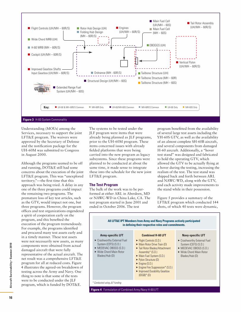
The SystemsFigure 3 (pg. 16) presents the similarity between the different H-60 Army and Navy platforms. As seen, the various versions of the aircraft have extensive commonality and a joint program seemed to be a very logical approach. The LFT AO proposed a breakdown of testing between the Services as an initial strategy, and the IPT had to refine it. Now, the challenge was to determine how to split the work across the programs and between the Army (ARL/SLAD in Aberdeen, MD) and the Navy (Naval Air Weapons Center-Weapons Division (NAWC-WD) in China Lake, CA).
Live Fire Test and Evaluation StrategiesBefore addressing the specifics of the joint LFT&E program, it is prudent to review the preparation for the waiver from FUSL testing. As indicated earlier, the UH-60M PM, as well as the MH-60R and MH-60S PMs, requested waivers from FUSL testing. Recall that a waiver only waives the requirement for testing of a production, full-up system, configured for combat; however, the need to perform system level dynamic testing still remains. The first thing that a program needs to accomplish in the waiver process is to prepare an alternate strategy to adequately evaluate the system’s vulnerability. During this process, the LFT AO is instrumental in working with the program to formalize these plans and DOT&E must approve the Alternate LFT&E Strategy before a waiver can be requested.
The foundations of the programs’ alternate LFT&E strategies were to use a production representative, operational ground test vehicle (GTV) for full-scale dynamic testing, and complement it with component and sub-system level static and dynamic testing. The GTV was a prototype YCH-60S that had been used on earlier H-60 programs to demonstrate performance of various new systems added to the original design. The availability of this asset reduced the LFT&E cost significantly.
The UH-60M, MH-60R, and MH-60S prepared separate waiver request packages tailored for their specific programs. The programs also prepared appropriate Memoranda of
Air
craf
t Sur
viva
bili
ty •
Sum
mer
201
0
15
Figure 2 LFT&E Program Tasks
1 Review LF&E Requirements
2
Develop Alternate LFT&E Strategy to Support Waiver Request, Formulate Combined Army-Navy LFT&E Program, Major Concerns
3Review LFT&E Plan, Program Summary, and Schedule LFT&E Events
4Approve TEMPs and Review LFT&E Critical Issues
5Approve Live Fire Event Design and Detailed Test Plans
6 Observe Testing
7 Review Final Test Reports
8 Prepare an Independent Assessment
Understanding (MOUs) among the Services, necessary to support the joint LFT&E program. The waivers were approved by the Secretary of Defense and the notification package for the UH-60M was submitted to Congress in August 2000.
Although the programs seemed to be off and running, DOT&E still had some concerns about the execution of the joint LFT&E program. This was “unexplored territory;”—the first time that this approach was being tried. A delay in any one of the three programs could impact the remaining two programs. The premature loss of key test articles, such as the GTV, would impact not one, but three programs. However, the program offices and test organizations engendered a spirit of cooperation early on the program, and this benefited the execution of the program tremendously. For example, the programs identified and procured many test assets early and in a timely manner. These test assets were not necessarily new assets, as many components were obtained from actual damaged aircraft that were fully representative of the actual aircraft. The net result was a comprehensive LFT&E program for all at reduced costs. Figure 4 illustrates the agreed-on breakdown of testing across the Army and Navy. One thing to note is that some of the tests were to be conducted under the JLF program, which is funded by DOT&E.
The systems to be tested under the JLF program were items that were already being planned as JLF programs, prior to the UH-60M program. These items concerned issues with already fielded platforms that were being carried into the new program as legacy subsystems. Since these programs were planned to be conducted at about the same time, it made sense to integrate these into the schedule for the new joint LFT&E program.
The Test ProgramThe bulk of the work was to be per-formed at either ARL in Aberdeen, MD or NAWC-WD in China Lake, CA. The test program started in June 2001 and ended in October 2006. The test
program benefitted from the availability of several large test assets including the YH-60S GTV, as well as the availability of an almost complete SH-60B aircraft, and several components from damaged H-60 aircraft. Additionally, a “hover test stand” was designed and fabricated to hold the operating GTV, which allowed the GTV to be actually flying at a hover during the testing, increasing the realism of the test. The test stand was shipped back and forth between ARL and NAWC-WD, along with the GTV, and each activity made improvements to the stand while in their possession.
Figure 5 provides a summary of the LFT&E program which conducted 144 shots, of which 40 tests were dynamic,
Air
craf
t Sur
viva
bili
ty •
Sum
mer
201
0
16
Army-specific LFT Combined H-60 LFT Navy-specific LFT Crashworthy External Fuel
System (CEFS) (S.D.) MEDEVAC OBOGS (S.D.) Wide Chord Main Rotor
Blades/Hub (D)
Flight Controls (S.D.) Main Rotor Drive Train (D) Tail Rotor Blades/Attachment
Assembly* (S.D.) Main Fuel System (S.D.) Pylon Structure (D) Engine (S.D.) Engine Fire Suppression* (S.D.) Improved Durability Gearbox
(IDGB)* (D)
Crashworthy External Fuel System (CEFS) (S.D.)
MEDEVAC OBOGS (S.D.) Wide Chord Main Rotor
Blades/Hub (D)
* Conducted using JLF funding
All LFT&E IPT Members from Army and Navy Programs actively participated in defining their respective roles and commitments.
Figure 4 Formulation of Combined Army/Navy H-60 LFT
MH-60R OnlyUH-60 & MH–60R/S Common UH-60/MH-60S Common MH-60R/S Common UH-60 Only MH-60S Only
Flight Controls (UH/MH – 60R/S)
Tail Rotor Assembly (UH/MH – 60R/S)
Vertical Pylon(UH/MH – 60R/S)
Rotor Hub Design (UH)
Tailbone Structure (UH)
OBOGGS (UH)
Folding Hub Design (MH – 60R/S)
Ordnance (MH - 60R/S)
Engines (UH/MH – 60R/S)
Main Fuel Cell (UH/MH – 60S)
Extended Range Fuel System (UH/MH – 60S)
Structural Design (UH/MH – 60S)
Main Fuel Cell (MH – 60S)
Tailbone Structure (MH – 60R)
Tailbone Structure (MH – 60S)
Wide Chord MRB (UH)
H-60 MRB (MH – 60R/S)
Cockpit (UH/MH – 60R/S)
Improved Gearbox Shafts Input Gearbox (UH/MH – 60R/S)
Key:
Figure 3 H-60 System Commonality

that is engines were running, rotor blades spinning, shaft rotating, fuel circulating, etc. The evaluation also included previous JLF tests (>400 tests) and combat data from Grenada, Turkey, Somalia and OIF/OEF. Testing included both armor-piercing incendiary (API) and High Explosive Incendiary (HEI) projectiles; with calibers ranging from 7.62 millimeters (mm) through 23mm. The sequence of testing followed a
“build-up” approach, progressing from developmental testing on static compo-nent samples, through static and dynamic testing on subsystems, to mostly dynamic system level tests.
Basically, system level testing builds on results of earlier testing to refine shotlines and threats to reduce more costly testing on full-up assets. The early testing on components and subsystems allows time for the design to be affected. And as the testing progresses from component to system level, the sophistication of the tests increases, but the number decreases.
For the subsystem type tests, the objective was to look at combined threat effects on a complete functioning subsystem, such as fuel system, engines, drive shafts, or rotor blades. These tests build on the findings from the earlier component testing, and they most likely include quasi-static loading or be dynamic in nature; i.e., operating. These tests usually also include post-ballistic loading representative of a get-home capability, in order to determine any synergistic or cascading damage effects.
The UH-60M LFT&E focused on expected real-world threats that were neither benign nor overmatching, i.e.,
threats that were not expected to kill the aircraft on every hit: 7.62mm ball, four API projectiles (7.62mm, 12.7mm, 14.5mm, and 23mm) and two HEI projectiles (23mm and 30mm). As indicated above, the LFT&E strategy used a building block approach (i.e., testing components and sub-systems before proceeding to system-level testing) to maximize knowledge gained and minimize risk and uncer-tainties. Specifically, the UH-60M LFT&E program focused on the ballistic vulnerability of the following aircraft subsystems—
➤➤ Internal Main Fuel (fuel tanks, associated plumbing, and dry bay areas next to the tanks)
➤➤ Main Rotor Blades➤➤ Main Rotor Flight Controls➤➤ Main Rotor Drive Train Subsystem➤➤ Tail Rotor Blades and Subsystem➤➤ Tail Rotor Pylon Structure➤➤ Engine➤➤ Engine Nacelle Fire Detection/Suppression System
➤➤ Crashworthy External Fuel System (CEFS)
➤➤ Cockpit (program used CH-47F LFT data).
Data from CH-47F vulnerability testing was useful because of the similarities between UH-60M and CH-47F CAAS cockpit components, crew seats, and surrounding structure. The CH-47F program conducted an extensive ballistic evaluation employing both component-level and a full-scale cockpit series of tests. The LFT&E IPT members, including DOT&E and IDA representatives, felt that this would be satisfactory for this evaluation.
The LFT&E program also provided opportunities to identify, develop, and test Battle Damage Assessment and Repair (BDAR) techniques. The US Army Aviation Logistics School at Fort Eustis, VA, provided support in BDAR for the live fire tests at the ARL. This information will be used by the Army to expand the current doctrine, type, and extent of combat damage that can be repaired in the field.
Conclusions and RecommendationsOverall, the testing showed that the UH-60M has low vulnerability to several of the threats tested, including threats larger than the 7.62mm API threat. However, there are some areas where the UH-60M remains potentially vulnerable to impacts from certain types of projectiles or high-velocity fragments.
In concert with the DOT&E OT AO, an integrated OT-LFT assessment of survivability was also performed. The results from the OT program indicated that against infrared threats, the UH-60M is less likely to be hit by threat systems than legacy aircraft. Against radio frequency (RF) threats, the UH-60M uses an out-dated radar-warning receiver that will be the subject of separate Army upgrades, and if hit, the UH-60M has survivability equal to or better than the legacy aircraft. Also the UH-60M is no more vulnerable to electronic warfare (EW) threats than its predecessors, and the UH-60M provides new or proven technologies to protect the crew and passengers.
DOT&E also made several recommen-dations to the programs addressing vulnerabilities seen in testing that could be improved on, making an even more survivable platform. These included using new procedures for use of transmission filters and boost pumps, and the addition of fuel fire and explosion protection features. DOT&E also noted some analyses yet to be completed, namely an evaluation of the use of monolithic machined structure and ballistic testing of the main rotor mast and modular add-on ballistic armor. Several of these recommenda-tions have been addressed under the DOT&E JLF program.
At the conclusion of testing, DOT&E, along with IDA’s support, is responsible to report to the Secretary of Defense and Congress, an evaluation of the test
Air
craf
t Sur
viva
bili
ty •
Sum
mer
201
0
17
Return toBase
LandingAttempt
TransitionFailure
Post-LandingSurvival
Immediate Lossof Aircraft
Flight-CriticalBallistic Damage
Flight-CriticalAircrew Injury
PersonnelCasualties
ControlledEgress/Ejection
PersonnelSurvival/Injuries
AirborneEgress/Ejection
Post-LandingSurvival
PersonnelSurvival/Injuries
CrewEgress
Post-LandingSurvival
PersonnelSurvival/Injuries
ForcedLanding/Ditching Crew
Egress
Post-LandingSurvival
PersonnelSurvival/Injuries
Post-LandingSurvival
PersonnelSurvival/Injuries
AirborneEgress/Ejection
PersonnelSurvival/Injuries
Successful LandingSurvival/Injuries
FLOT
COVART/AJEM plus casualty
Survival Timeline
ForcedLanding/Ditching
Full-up/Full-scale System Level (FUSL) Testing (dynamic)
Subsystem Level Testing(static and dynamic)
Component Level Testing(mostly static)
Development Testing(Continues thru FUSL)
FUSL testing builds on earlier testing to refine shotlines and threats reducing more costly testing on full-up assets.
LFT&E program conducted 144 shots; including 40 dynamic tests LFT&E also included previous JLF tests (>400 tests), and combat data from Grenada,
Turkey, Somalia, OIF/OEF Tested both API and HEI projectiles (7.62mm through 23mm)
Testing early allows design changes and fixes to
be implemented before full-rate production
Decreasing number of tests
System IntegrationLaboratory Testing
Existing Test and Combat Data
Figure 5 LFT&E Program Summary
Continued on page 31

Air
craf
t Sur
viva
bili
ty •
Sum
mer
201
0
18
The United States Marine Corps’s (USMC) H-1 Upgrade Program is a major step in the continuing evolution of the power plant, dynamic systems, armaments, and avionics of the H-1 series helicopter. Improvements have been incorporated for range, power, speed, combat survivability, crash survivability, and reduced tailboom heating. Major upgrades to the AH-1Z and UH-1Y aircraft address the dynamics (rotors, drive, and propulsion), weapon subsystems, cockpit and integrated avionics. New four-bladed, all-composite rotor systems (main rotor and tail rotor) are coupled to an improved engine and drivetrain system that includes a new main transmission and new tail rotor drive gearboxes. Aircraft utilities are enhanced with a new auxiliary power unit (APU) and improved hydraulic and electrical systems. The weapons and avionics systems are fully integrated with an all-glass cockpit. The upgraded aircraft was designed to provide increased operational capability, reduced life-cycle
cost, and improved performance relative to the AH-1W and UH-1N aircraft. For the USMC, the most significant advantage of this upgrade is the 84% commonality between AH-1Z and UH-1Y, which will reduce life cycle cost and logistics footprint. The significant components that are common to both helicopters are shown in Figure 1.
Designed for SurvivabilitySurvivability has been paramount in the H-1 Upgrade design since the program’s inception and was the first Department of Defense (DoD) Live Fire Test and Evaluation (LFT&E) program to conduct a Full-Up System Level (FUSL) ballistic test prior to full-rate produc-tion on an aircraft configured for combat. This extensive program included all dynamic components and concluded with a successful full-up test of an AH-1Z aircraft.
While both aircraft (and their Bell H-1 predecessors) have long filled attack and utility roles in the Services, upgrades of
these product lines through the years have not included significant survivability technology enhancements. The current H-1 Upgrade Program breaks from that pattern, with survivability criteria being a major driver of the designs. Particular attention has been given to ballistic tolerance, reduction of infrared signature, and advanced electronic countermeasures. Building on the commonality of the two aircraft, all of the survivability enhancing features are common to both aircraft and are identical with the exception of the fuel system installations and some portions of the crew armor. Where commonality exceptions exist, the differences are due to unique installation considerations, with comparable survivability improvements in each design.
Ballistic tolerance provided through redundancy, materials, and key design features, is instrumental in the H-1 Upgrade survivability improvement. Vulnerability to ballistic threats has been significantly reduced in both aircraft. System design and advanced composite material construction have produced an all-composite main rotor system and tail rotor system that has an increased ballistic tolerance over the rotor system in the AH-1W and UH-1N. The main rotor rotating controls system has also been designed for improved ballistic tolerance, with complementary up-sizing of the main and tail rotor fixed controls systems. Live fire testing of an operating AH-1Z demonstrated that the main rotor blades and tail rotor blades continued to operate for 30 minutes following ballistic impact. The tail rotor gearbox also continued to operate for 30 minutes following loss of oil due to ballistic impact.
AH-1Z and UH-1Y: Designed for Survivability
By Darrell Liardon and Michael Kouvarakos
Survivability is improved in both the AH-1Z and UH-1Y aircraft through enhanced ballistic hardening, signature reduction, and improved electronic countermeasures. Mission effectiveness is improved with the new cockpit and integrated avionics systems; increased weapons quantities and accuracy; and improved speed, range, and payload capabilities.
Complete Drive System (main, combining, 42 and 90 degree gearboxes, and shafting)
Auxiliary Power Unit Main Rotor System Main Rotor Folding Provisions Tail Rotor System Engine and APU Compartment Fire Detection
and Suppression Gearbox Oil Cooling Tailboom T700-GE-401 Engine Hydraulic Components Engine Exhaust IR Suppressors Turned Exhaust—Reduced Tailboom Heating Selected Electrical Components
(battery, starter, generators, etc.)
Figure 1 AH-1Z and UH-1Y: 84% Commonality

Air
craf
t Sur
viva
bili
ty •
Sum
mer
201
0
19
The aircraft hydraulics systems have been simplified while reducing their vulnerability. A “smart” feature in the dual hydraulic systems minimizes fluid loss, depressurizes damaged hydraulic circuits, and maximizes the post-damage hydraulic pressure to the dual-tandem main rotor control actuators. The removal of the dedicated utility system of the current AH-1W has saved weight and cost, increased reliability and commonality of hydraulic system components, reduced maintenance, eliminated the probability of a sustained hydraulic fire, and reduced vulnerable area. In addition to dual main rotor actuators, the tail rotor boost actuator is also of dual-tandem design, with fly-through capability if both systems lose pressure. Finally, the Stability and Control Augmentation System (SCAS) actuators have been incorporated into the primary control actuator units, reducing parts count, hydraulic line routing, and hydraulic system ballistic vulnerability.
The fuel system is protected from internal explosion by an on-board inert gas generation system (OBIGGS). The fuel systems are self-sealing and crashworthy in accordance with MIL-T-5578. Dry bay protection is provided around all fuel cells, employing optimized combinations of reticulated foam, composite backing board, and powder-filled panels. Fire protection is provided for both engine compartments and the APU compartment with firewalls, fire detection, and pilot selectable fire extinguishing. The current fleet Halon systems are replaced by environment-friendly HFC 125.
Crew protection is enhanced by the replacement of the existing pilot/copilot fixed armored seats with energy attenuating armored buckets. The UH-1Y seats come with new panels integral to the seat design, retaining the provisions for additional armor. The AH-1Z installation utilizes the existing airframe-mounted panels. The crew protection provided by the new armor systems is increased in both aircraft, as well as the crash protection provided by the energy attenuation features of the new seats. The troop seats also provide the same energy attenuating features for personnel in the back of the UH-1Y.
Infrared signature reduction is provided, while maintaining the Cobra’s low visual silhouette. The General Electric (GE) Hover Infrared Suppression Systems (HIRSS) has been coupled to the T-700 engines, an infrared suppressor configuration similar to that of the US Army/Sikorsky UH-60 Black Hawk. The principal difference in the H-1 installation is in the transition stage from the turbine outlet into the main suppressor unit. This transition stage has been designed by Bell with GE technical support to optimize suppressor-cooling airflow, while allowing removal of the engine without removing the suppressor or transition stage. Improved exhaust seals and engine compartment cooling are additional benefits of the new, suppressed-exhaust design. In addition to the enhanced IR suppression system, the exhaust structures were canted outboard to eliminate tailboom structural issues caused by heating of the tailboom.
These new survivability features are complemented by an integrated electronic countermeasures (ECM) suite that includes AN/APR-39B(V)2 radar warning, AN/AAR-47B(V)2 missile warning, laser warning functionality, and flare/chaff expendables with four AN/ALE-47 countermeasure dispensers. The AH-1W and UH-1N aircraft have only two countermeasure dispensers. The ECM provides pilot-selectable (automatic, semi-automatic, or manual) dispensing of flares, chaff, and decoys. These survivability features are maximized on both air vehicles, due both to the extensive commonality of the aircraft and the similarity of the combat threat environments. This commonality reduces cost, enhances supportability, and results in increased survivability.
Mission EnhancementMissions for the AH-1Z include close air support (CAS) and Armed Escort. Missions for the UH-1Y include Casualty Evacuation (CASEVAC), and Tactical Recovery of Aircraft and Personnel (TRAP). Studies were conducted during engineering and manufacturing development (EMD) using Bell Helicopter’s Tactical Mission Analysis Station (TMAS) to compare probabilities of survival for the Upgrade AH-1Z and UH-1Y compared to the Legacy AH-1W and UH-1N for the assigned missions. Each of the aircraft
was characterized by its infrared (IR) signature, radar cross-section, ballistic vulnerability, ECM gear, weapons load, aerodynamics and power. Digital terrain data, threat design data and threat locations were used to define the combat environment. Studies showed a signifi-cant increase in probabilities of survival for the Upgrade aircraft over their legacy counterparts.
Combat DeploymentThe UH-1Y (Yankee) recently deployed to Afghanistan to support US and coalition forces. Marine Light Attack Helicopter Squadron 367 (HMLA-367) deployed with their Yankees in October 2009. The UH-1Y helicopters were transported to Camp Bastion in South Central Afghanistan. The AH-1Z (Zulu) is expected to receive approval for Full Rate Production in the fourth quarter of 2010.
ConclusionThe AH-1Z and UH-1Y are the most affordable and effective solutions for the primary USMC rotary wing aviation missions. The commonality of these two aircraft yields reduced required maintenance manpower, parts inventories, and training requirements. The benefits of common aircraft components greatly reduce the logistics tail as the aircraft are deployed, afloat or ashore. The AH-1Z adds more range and firepower, greater accuracy, superior sensors, and automated battle management, all of which are combat force multipliers for the USMC. The UH-1Y provides increased speed, range, and survivability in combat missions, coupled with increased payload, range, and endurance in its combat support roles. The AH-1Z and UH-1Y air-vehicle performance, integrated systems, weapons accuracy, load-out increases, and survivability benefits provide the USMC with enhanced capabilities on tomorrow’s battlefield. n

Air
craf
t Sur
viva
bili
ty •
Sum
mer
201
0
20
V-22 Integrated Survivability Design Approach
by Robert Laramee
The V-22 tiltrotor is a radically different aircraft approach than previous Vertical Take-Off and Landing (VTOL) aircraft designs with a high wing and two pivoting engine nacelles which allow conversion from vertically oriented rotors for take-off, landing and hover operations to a horizontally oriented rotor for high speed forward flight like any turboprop airplane. This flexible nature of the V-22 configuration allows it to operate in a broad flight envelope, which encompasses both attributes of a helicopter and fixed-wing aircraft into
one versatile aircraft as well as folding wing and proprotors for storage or shipboard operations. The movable engine nacelle allows the V-22 to achieve greater speeds than a helicopter, which adds another dimension to its survivabil-ity and reduction of exposure to threats. The dynamics of the V-22 changes the operational paradigm of the respective users opening up greater operational ranges capability, reduced crew fatigue, less predictability, and enhanced mission planning flexibility. The V-22 utilizes two Rolls-Royce AE1107C engines with
an interconnect drive shaft for one engine operation (OEI) capability. This is the first of many redundancies of the V-22 design to meet its survivability requirements.
The V-22 has specific Naval Air Systems Command (NAVAIR) driven aircraft vulnerability programmatic requirements and was a lead aircraft subject to Office of the Secretary of Defense (OSD) oversight with the Live Fire Test Law passed in 1987. The V-22 with these many programmatic requirements had an
The first V-22 Osprey production aircraft have successfully completed their Initial Operational Testing and Evaluations as well as their respective Initial Overseas Deployments for both the MV-22 and CV-22 variants. The V-22 tiltrotor is in use by the US Marine Corps (USMC) with the MV-22B and the US Special Operations Command (USSOCOM) via the CV-22. The V-22 replaces the 48-year-old CH-46 in the medium lift Marine inventory for assault support. The CV-22 is used for a range of USSOCOM missions including deep infiltration/exfiltration. Both V-22 aircraft have the same basic aircraft structure and engines with slightly different avionics and electronic warfare equipment installations to meet their respective operational requirements. This discussion will review the survivability features of both aircraft.
Rotary Wing Combat Non-Hostile Losses(157 Events)
Fire, 7
Other MechanicalFailures, 2 Weather
Awareness, 2
WeatherAwareness, 2
Other MechanicalFailures, 2
Fire, 7Power Train
Failure, 4Wire Strike, 9
Inadvertent IMC, 7
Midair Collision, 10
Object Strike (Cruise), 5
Flatt Hatting, 2DVE, 38
Object Strike(Landing, Hover, Taxi), 11
Pr>Pa, 9
Loss of Control (Pilot Error), 6
Hard Landing/Dynamic Rollover, 3
Other Human Factors, 2
Flight Related, 7
Engine Failure(Mechanical), 12
Loss of Control(Mechanical), 6
Controlled FlightInto Terrain (CFIT), 15
Rotary Wing Combat Non-Hostile Fatalities(219 Fatalities)
Loss of Control(Mechanical), 19
Engine Failure(Mechanical), 22 Controlled Flight
Into Terrain (CFIT), 47
Wire Strike, 16
Inadvertent IMC, 64Midair Collision, 18
Object Strike (Cruise), 3
Flatt Hatting, 1
DVE, 8
Object Strike(Landing, Hover, Taxi), 10
Other Human Factors, 2
Flight Related, 6
Rotary Wing Non-Combat Losses(148 Events)
Controlled Flight Into Terrain (CFIT), 21
Wire Strike, 9
Inadvertent IMC, 11
Midair Collision, 4
Object Strike (Cruise), 3
Flatt Hatting, 1DVE, 7
Object Strike(Landing, Hover, Taxi), 12
Pr>Pa, 9Loss of Control(Pilot Error), 14
Hard Landing/Dynamic Rollover, 13
Other Human Factors, 6
Flight Related, 4
Engine Failure (Mechanical), 9
Loss of Control (Mechanical), 5
Power TrainFailure, 5
Fire, 6
Other Mechanical Failures, 4
Weather Awareness, 2Undetermined, 3
Rotary Wing Non-Combat Losses(148 Events)
Wire Strike, 9
Inadvertent IMC, 33Midair Collision, 4
Object Strike (Cruise), 4
Object Strike(Landing, Hover, Taxi), 1
Pr>Pa, 7
Loss of Control (Pilot Error), 14
Hard Landing/Dynamic Rollover, 4
Other Human Factors, 2
Flight Related, 3 Fire, 5Other Mechanical Failures, 2
Controlled Flight Into Terrain (CFIT), 39
Engine Failure (Mechanical), 1
Human Factors–Cruise Flight Human Factors–Hover/Low Speed Non-Human Factors–Mechanical
Performance Speed Range Altitude Maneuverability
Tactics Day/Night High/Low-Level All Weather
Signature Reduction Visual Acoustic Infrared EMCON
Defensive Weapon Systems
EW Warning & Countermeasures
Self Sealing Fuel System
One Engine Inoperative Capability
Dry Bay & EngineFire Suspension
System Protection Armor Isolation Redundancy Separation
Ballistic Tolerance Composite Structure Hydraulic Ram Protection Self-Sealing Fuel Bladders Nitrogen Inerted Fuel System
Ditching Bouyancy, Stability & Emergency Egress
Stroking Seats & Shoulder Harnesses for Troop & Crew
Energy Management “Broomstraw” Blade Failure Mass Remote Design Controlled Wing Failure Anti-Plow Bulkhead Attenuating Cargo
Restraints
REDUCED SUSCEPTABILITY REDUCED VULNERABILITY + = IMPROVED SURVIVABILITY
Figure 1 V-22 Survivability Features Address Broad Spectrum Threats

Air
craf
t Sur
viva
bili
ty •
Sum
mer
201
0
21
extensive live fire testing program depicted in Figure 2. The live fire test program was utilized to validate compu-tational vulnerability analyses and demonstrate component and system performances in flight load environments. The aggressive vulnerability requirements drove evaluation of any and all vulner-ability reduction technologies to meet the aircraft system requirements within the aircraft Key Performance Parameters (KPPs). The basic aircraft design mission of low altitude ingress to contested landing zones was a significant driver of vulnerability reduction incorporation. The aircraft capabilities and operational tactics are still evolving but the V-22 high-altitude, high-speed capability is already being utilized to further reduce its exposure to man portable threats. The fielded V-22 airframe has a wide range of both active and passive integrated vulnerability reduction technologies, which are too large to practically list. Figure 3 includes a summary of the methods or technologies incorporated in the V-22 aircraft design. The vulnerabil-ity reduction technologies had to buy their way onto the aircraft in the effort to meet vulnerability requirements and weight efficiencies to enable the V-22 achieve its required various mission range and altitude performance requirements.
Ballistic Vulnerability ReductionFigure 3 includes a listing of the wide-ranging vulnerability reduction tech-niques that have been utilized to meet the vulnerability reduction of the V-22
airframe. These technologies range from inherent structural design requirements such as multiple load paths and allowable load requirements to active fire suppres-sion systems to prevent sustained fire in the aircraft. All the technologies were extensively tested at the component and subsystem level and demonstrated in flight aircraft structure configurations. This included ballistic testing with aircraft flight load levels and for fire suppression testing with flight air flows for representative conditions and confirmation of system sizing.
Nuclear, Biological, and Chemical (NBC) The V-22 structure and systems were required to meet specific nuclear, biological, and chemical (NBC) contami-nation requirements. These requirements combined with shipboard compatibility and lightning strike drove Electromagnetic interference (EMI) reduction efforts for both system components and aircraft structure protection feature incorporation. The embedding of copper mesh electrical paths incorporated in the composite laminates to provide both shielding and electrical energy dissipation is an example of multiple use reduction technologies. The V-22 aircraft material selections were given consideration with respect to NBC contamination resistance, adherence and absorption. The V-22 was designed to promote decontamination by minimizing entrapment areas as well meeting
operational capability standards for both operator and maintainer in their NBC protective ensembles.
SignatureThe V-22 has low visual, acoustic, and infrared (IR) signatures due to its design features. The widely-separated nacelles with integrated IR suppressors prevents plume impingement on airframe compo-nents, eliminates turbine direct-line-of-sight, increases plume mixing, and cools exhaust components eliminating many IR signature sources. The movable nacelle and rotor system reduces the projection of acoustic energy toward oncoming objectives compared to a standard rotorcraft. These features reduce the susceptibility of the V-22 to ballistic and guided missile systems.
Threat Sensing and CountermeasuresThe MV-22B has an integrated Electronic Warfare (EW) suite utilizing the AN/APR-39A(V)2 as an EW bus
Figure 3 V-22 Airframe Incorporated Ballistic Vulnerability Reduction Technologies
System and Component Redundancy
Separated components
Fail Safe design principles
Multiple Load Paths
Engine Dual Redundant Full Authority Digital Electronic Control
Dual Fuel Management Units
Three Independent Hydraulics Systems
Triplex fly-by-wire Flight Computer Controls
Swashplate Actuators—electrical and hydraulic redundancy with integrated armor
Emergency lubrication system (ELS) for the proprotor gearboxes (PRGBs)
Fire Suppression
Suction Feed System
OBIGGS On-Board (Nitrogen) Inert Gas Generating System
Self-Sealing Crashworthy Fuel Cells
Ballistic Foam
Aluminum Oxide Powder Panels
Mid-Wing Thermal Insulation Blankets
Active Detector/Suppression units for mid-wing, wing aft cove, inboard, outboard dry bays, and engine suppression
Integral Armor
Singularly Vulnerable Flight Control Components
Pilot Seats
V-22 LFT&E Program Events
1992 1994 1996 1998 2000 2001
EMD Contract AwardOctober 1992
Initial AssessmentOctober 1994
Interim AssessmentJune 1998
Final LFT Report to OSD
October 2000
Final AssessmentMay 2001
FSD & EMD Wing Feed Cell Hyd Ram Graphite Skin-Stringer Panels Telescoping Ballscrew Shafts Wing Hyd Ram Phase I Dry Bay Fire Protection
System PRGB Components Pitch Link CBR Filter Elevator Actuator Rotor Mast Wing Fire Protection Wing Hydraulic Ram Wing Structure Pylon Conversion Spindle
EMD T56 Engine T406 Engine Fuselage Structure/Hyd
Ram Mid-Wing Fire Protection PRGB Swashplate Rotating Ring Upper Nacelle Fire Pitch Horn Horizontal Stabilizer Wing Aux Tanks Hyd Ram Pylon Driveshaft Wing Drive Shaft & Hanger
Bearings
EMD Transmission Adapter Conversion Actuator Wing Tip Rib Prop Rotor Blades PRGB Demo TAGB Demo Fuselage/Sponson Hyd
Ram/Fire Swashplate Actuator Prop Rotor Grip/Yoke Conversion Actuator
Spindle STA EMD Verification Demo Aft Sponson Fuel Cell
Post Production Main Landing Gear Bay Fire
Protection Ballistic Tests 2003
IRAD Underfloor Fire Protection Testing 2004
MLGB Fire Protection 2006 SARAP Hydrodynamic Ram
Characterization 2004-5 NAVAIR MANPAD 2007 IRAD Hydrodynamic Ram
Joint Testing 2007 CRAD Flare Dispenser
Testing 2008-9 IRAD Testing 2009-10
– Multi-Functional Panels – Fire Protection
60 Individual Tests, 592 Total Live Fire Shots During LFT&E Program
Figure 2 V-22 Live Fire Test & Evaluation Program Events

Air
craf
t Sur
viva
bili
ty •
Sum
mer
201
0
22
controller and radar warning receiver. The MV-22B was recently upgraded to the AN/AAR-47B(V)2 laser and missile warning system. Both warning systems are integrated with the AN/ALE-47 countermeasure system to dispense chaff and flares. The MV-22B Block C has three dispensers located on each aft sponson and one forward mounted below the crew compartment. The installation allows the correct expend-able type response needed to counter any approaching threat system via manual, semi-automatic, or automatic response from either radar or missile warning receiver systems. The counter-measures can be tailored to optimize the countermeasure (CM) response based upon aircraft speed, altitude, attitude, and other aircraft parameters. The tailored CM responses have been flight tested with excellent results. For the future, the MV-22B was selected as the lead integration aircraft for the Joint and Allied Threat Awareness System (JATAS) currently in competi-tion as a replacement for the AN/AAR-47 family of Missile Warning System (MWS) installations.
The MV-22 Block C incorporates the forward AN/ALE-47 dispenser for enhanced countermeasure effectiveness for counter-countermeasure capable Man-portable air-defense systems (MANPAD) threats. Bell-Boeing working with PMA-275 was able to integrate and retrofit deployed Block B aircraft with the forward dispenser capability to support MV-22 operations of VMM-263. This addition has been shown to be very effective in captive seeker and Hardware-in-the-Loop testing.
The CV-22 has a different integrated EW suite reflecting the different requirements of the USSOCOM missions. The CV-22 EW bus controller or EW data manager is the AN/ALQ-211 Suite of Integrated Radio Frequency Countermeasures (SIRFC), which is connected to the Multi-Mission Advanced Tactical Terminal, AN/ALQ-24 Directed Infrared Countermeasures (DIRCM), and the AN/ALE-47 Countermeasures Dispenser System.
The SIRFC system provides all threat display management, Electronic Order of Battle data handling, radar warning capability, active jamming, expendable countermeasure queuing to the ALE-47 against radar guided threat systems, and threat warning crew interface on the Dedicated EW Display. The SIRFC system utilizes multiple transmit and receive antennas distributed around the aircraft to provide spherical coverage against radio frequency (RF) threat systems.
The DIRCM integration into the CV-22 consists of the AN/ALQ-24 system with the AN/AAR-54 missile warning
sensors and dual small laser turret assemblies. As a product improvement, the latest generation of IR jammer system is being integrated to replace the small laser turret assemblies with the Guardian Laser Transmitter Assembly (GLTA). Either installation is integrated with the SIRFC system and the AN/ALE-47 Countermeasure Dispenser System. The CV-22 countermeasures integration is similar to the MV-22B already discussed, except with two dispensers at each location which doubles the number of expendables available to counter radar or IR guided MANPADs and other threat systems.
The tiltrotor V-22 has an integrated approach to survivability by its inherent design features and subsystem implemen-tation. These features individually cannot protect an aircraft from the comprehen-sive threats on the battlefield, but the V-22 as a whole combines its many attributes of structures, ballistic toler-ance, fire suppression, redundancy, low susceptibility, and EW countermeasures for a robust survivable aircraft design. n
Wing Auxiliary Fuel Cell Hydraulic Ram Ballistic Test
High Explosive Incendiary
Shot #3Shot #4Shot #5
Figure 4 V-22 Wing Component Demonstrating Successful Multi-Shot Capability Under Flight Static Loads During Ballistic Testing
Figure 5 Successful MV-22B Forward Dispenser Integration Safe Separation Flight Test

Air
craf
t Sur
viva
bili
ty •
Sum
mer
201
0
23
Mark earned a Bachelor of Science degree in Chemical Engineering and a Bachelor of Science degree in Chemistry in 1984 from Purdue University. After graduation, he entered the Navy receiving his commission through Aviation Officers Candidate School and immediately reported to flight training at Whiting Field in Milton, Florida. Upon earning his wings in March 1986, he reported to Helicopter Mine Countermeasures Squadron Twelve (HM-12) for flight training in the RH-53D. Afterwards, he joined the Helicopter Mine Countermeasures Squadron Fourteen (HM-14), home-ported in Norfolk, Virginia, serving in the Operations and Maintenance Departments. During this tour, the squadron was rapidly deployed to the Arabian Gulf to conduct mine
countermeasure operations in support of Operation Earnest Will. He was embarked on USS GUADALCANAL, USS OKINAWA, and USS LASALLE during the deployment. After comple-tion of this tour, he reported to the Commander, US Atlantic Fleet as the Aide and Flag Lieutenant to the Deputy and Chief of Staff.
In 1991, Mark reported to the Naval Postgraduate School in Monterey, California, to begin his graduate studies in Aeronautical Engineering. He earned a Master of Science in Aeronautical Engineering (with Distinction) in September 1993. His research was in the field of unsteady aerodynamics with his thesis titled “A Finite Wake Theory for Two-Dimensional Rotary Wing Unsteady Aerodynamics.” After completing his studies, he reported to HM-14 again and served as the Aviation Safety Officer where he investigated a Class A mishap. He later reported to Commander, Helicopter Tactical Wing, US. Atlantic Fleet where he served as the Wing Operations Officer and Safety Officer. In 1997, he reported back to HM-14 for a third tour as the Operations Officer and Administrative Officer while the squadron deployed aboard USS INCHON in the 6th Fleet and North Atlantic.
In 1999, Mark returned to the Naval Postgraduate School to serve as military faculty member in the Department of
Aeronautics and Astronautics. Shortly after arriving Dr. Ball approached him about teaching the graduate-level course in Aircraft Combat Survivability. Mark enthusiastically accepted, and then learned on Day 2 of his first offering of the course that he could not teach Bob Ball’s course as Bob taught it. Instead, Mark relied on his operational experi-ence to incorporate a warfighter’s perspective to the course, and eventu-ally developed an unclassified version of the course that allowed hundreds of international and non-resident students the opportunity to take the course via video teleconferencing. Concurrent with his military faculty responsibilities, he pursued his doctorate in Aeronautical Engineering receiving his PhD in June 2003. His dissertation was titled “A Three-Dimensional Flutter Theory for Rotor Blades with Trailing-Edge Flaps.”
His next assignment was to the staff of the Commander, Seventh Fleet on the USS BLUE RIDGE stationed in Yokosuka, Japan where he served as the Deputy Plans Officer and Assistant Operations Officer. His final tour in the Navy was as the Executive Officer at the NROTC Unit at the University of Illinois where he was the academic and career advisor to 120 undergraduate and 14 graduate students and taught courses in Leadership, Organizational Management, and Sea Power. During Mark’s Navy career, he flew approxi-mately 1500 flight hours in the T-34C,
Excellence in Survivability— Mark A. Couch
by Dale Atkinson
The JASP is pleased to recognize Dr. Mark A. Couch for Excellence in Survivability. Mark is a Research Staff Member for the Institute for Defense Analyses (IDA) supporting rotary wing projects in operational and live fire test for the Director, Operational Test and Evaluation in the Office of the Secretary of Defense. Recently, he led the Data Collection Working Group in support of a Congressionally-mandated Study on Rotorcraft Survivability. Prior to joining IDA, he served in the Navy for 23 years as a helicopter pilot flying the MH-53E Sea Stallion. He served as military faculty at the Naval Postgraduate School from 2000–2003 where he first became intimately involved in the aircraft survivability discipline by carrying on the work of Dr. Robert E. Ball upon Bob’s retirement. In 2003, Mark earned his doctorate in Aeronautical and Astronautical Engineering from the Naval Postgraduate School with his dissertation in Rotary Wing Unsteady Aerodynamics.
Air
craf
t Sur
viva
bili
ty •
Sum
mer
201
0
24
Other advanced engineering approaches —such as developing back-up/redundant systems that allow helicopters to continue the mission in either a full mission capable profile or a degraded mode of flight. Designs that extend safe flight when a system like a transmission, engine or gearbox is hit, damaged or fails, and fluids run dry—also serve to greatly enhance survivability. Fire protection is a significant capability in terms of saving both aircraft and personnel losses. While it does not receive as much attention as some of the other areas, it is an active research area improving capability and reducing penalties (space, weight, power). An example are simple passive systems that detect and suppress light weight, autonomous fires and do not require aircraft power or plumbed suppressing agent lines.
Crashworthiness was a central element of the lead in paragraph to this article and must be addressed upfront in the aircraft’s design. We must continue to
invest in and improve crashworthiness requirements and technologies to protect crew and passengers without hampering mission capability. This area not only benefits our Soldiers, Sailors, and Airmen in combat, it benefits them at all times.
Doing all that we can to protect those who protect usWe can accept that budget realities within the DoD preclude the fielding of all the new and emerging systems, including helicopters, that would be helpful in addressing the missions we face. What is much more difficult to accept is that the DoD and the Services have been unable to bring to bear needed improvements to the survivability of the fielded force.
The above discussion dissects helicopter survivability into its component parts—avoiding detection, avoiding a hit given detection, and surviving a hit—and posits areas of improvement that should be among those being aggressively pursued by the DoD and the Services in a balanced manner leading to tangible results.
I suggest focused investments with stable multi-year funding similar to the Army after Task Force Hawk and again with
the cancellation of the Comanche. These and other aircraft survivability enhance-ments are not just modest relative to the cost of new platforms, they are a moral imperative if we—as defense industry leaders—are to have the only acceptable answer to the question: “Have I done everything I can to protect those who serve to protect us?” n
Are We Doing Enough to Enhance the Survivability of Rotary Wing Aircraft? Continued from page 7
TH-57B/C, RH-53D, and MH-53E aircraft with 300 hours under tow. He has received three Meritorious Service Medals, four Navy Commendation Medals, a Navy Achievement Medal and four Battle “E” Awards.
Upon joining IDA in 2007, Dr. Couch began work in the Live Fire Project supporting Live Fire Test and Evaluation (LFT&E) efforts for the AH-64D Apache Block III, UH-60M Blackhawk, Armed Reconnaissance Helicopter, OH-58D Kiowa Warrior, MH-60S Armed Helicopter Weapon System, and the CH-53K Heavy Lift Replacement. Additionally, he sup-ported Initial Operational Test and Evaluation of the H-1 Upgrades program for the UH-1Y and AH-1Z.
In support of the congressionally mandated Study on Rotorcraft Survivability, Dr. Couch became the focal point for the data collected from all the services that included combat losses and damage, aircraft mishaps, and flight hour summaries. The final report contained the most detailed summary of
all rotorcraft losses from Vietnam to the current conflicts of Operation Enduring Freedom and Operation Iraqi Freedom and has been readily accepted as the authoritative source on rotorcraft losses and proposed solutions to reduce these losses. Additionally, he participated in another congressionally mandated study for the Future Vertical Lift Initiative that will develop capabilities based assess-ment and science and technology roadmap for the development of next generation helicopters.
Mark is an Executive Board member for the National Defense Industrial Association (NDIA) Combat Survivability Division, an American Institute of Aeronautics and Astronautics (AIAA) Associate Fellow, and a member of the Advanced Vertical Flight Committee for the American Helicopter Society. He has authored or coauthored numerous papers and articles in both aircraft survivability and rotary wing research. He has been married to the former Pamela Morgan of Rochester, Indiana since 1984, and they have three children.
It is with great pleasure that the Joint Aircraft Survivability Program (JASP) honors Dr. Mark Couch for his Excellence in Survivability contribu-tions to the JASP, the survivability discipline, survivability education, and as a warfighter. n

Air
craf
t Sur
viva
bili
ty •
Sum
mer
201
0
25
The CH-53K is designed to be survivable in a combat environment. Two of the seven Key Performance Parameters (KPPs) in the Operational Requirements Document (ORD) define requirements for force protection and ballistic tolerance to ensure a safe and survivable design that exceeds the current capabilities of the CH-53E. ORD requirements for missile warning and missile jamming or decoying further enhance the survivability capabilities of the platform. Flight tests, Live Fire Test & Evaluation (LFT&E) and ballistic risk reduction testing are being used to verify the performance of these capabilities against threats likely to be encountered in combat.
This article focuses on aircraft design driven by survivability requirements, and the continuous process of vulnerability analyses and ballistic testing. Figure 1 briefly highlights some features on the CH-53K related to vulnerability reduc-tion and force protection.
Survivability Assessment of the CH-53KIn support of the CH-53K development a detailed survivability study is being conducted for each significant design milestone to ensure the design is compliant with the Air Vehicle Specification (AVS) requirements. Efforts to support the two disciplines of survivability (susceptibility and vulnerability) are being conducted by an assessment team consisting of SAC, the SURVICE Engineering Company (SURVICE), and Naval Air Systems Command (NAVAIR). In addition to performing analytical studies, the Survivability Team is also conducting LFT&E and executing risk reduction ballistic testing at the Naval Air Warfare Center Weapons Division (NAWCWD), Weapons Survivability Laboratory, in China Lake, CA.
The vulnerability and force protection analyses are continuous processes being conducted to evaluate system, subsystem,
and component vulnerabilities using the Ballistic Research Lab Computer Aided Design (BRL-CAD) geometry modeling tool and the Computation of Vulnerable AReas Tool (COVART). Primary threats of interest are identified in the AVS and include ballistic threats as well as rocket-propelled grenades (RPG) and Man-Portable Air Defense Systems (MANPADS). Vulnerability and force protection analyses were completed for PDR. Additional assessments will be provided prior to CDR, Milestone C, and the Full-Rate Production (FRP) decision milestone.
The susceptibility analyses incorporate threat system and aircraft performance data, along with results of other simulation models, to assess system susceptibility against the threats specified in the AVS for both land assault troop lift and amphibious external lift missions. Results of these analyses identify the features of the system that determine its probability of exposure or engagement by threat systems and the effectiveness of the Aircraft Survivability Equipment suite (ASE). These results form the basis for required survivability assessments. A Mission Threat Encounter Analysis (MTEA) including an infrared (IR) susceptibility analysis was completed for PDR. A MTEA that includes IR and radio frequency (RF) susceptibility analysis will be provided prior to CDR, Milestone C, and the Operational Test Readiness Review (OTRR).
CH-53K Heavy Lift Helicopter— A Survivability Focused Design
by Nicholas Gerstner and Kathy Russell
The Sikorsky Aircraft Corporation (SAC) was awarded a System Development and Demonstration (SDD) contract in April of 2006 to design and build the next-generation heavy-lift rotorcraft platform for the US Marine Corps. The platform, designated as the CH-53K, is a ground-up re-design that incorporates the latest in helicopter technology, including new General Electric GE38-1B 7,500-hp engines, fly-by-wire flight controls, and composite airframe structures. The advanced capabilities of the drive and rotor systems will enable the aircraft to carry 27,000 lbs more than 110 nautical miles, which is three times the performance of its predecessor, the CH-53E. The CH-53K Preliminary Design Review (PDR) has been successfully completed in September 2008, and the Critical Design Review (CDR) is upcoming in Fall 2010.

Air
craf
t Sur
viva
bili
ty •
Sum
mer
201
0
26
Results from the susceptibility and vulnerability analysts will be combined to conduct survivability assessments for the threat platforms identified in the AVS. The first series of assessments is in progress and will be completed prior to CDR. Additional assessments will be provided prior to MS-C and OTRR.
The CH-53K program is designated as a covered LFT&E system under US Code Title 10, Section 2366 (10USC2366). However, the program submitted a waiver and has received approval to proceed with an Alternative LFT&E (ALFT&E) strategy. ALFT&E efforts will leverage the conclusions drawn from the survivability analysis efforts to aid in identification of viable test shots. In addition, the information obtained from the ALFT&E will provide verification of the vulnerability assess-ment, a crucial insight into the perfor-mance of a previously untested system, and a better understanding of complex ballistic events (e.g., fire initiation and propagation, dynamic performance of damaged components/systems, and effects on occupants).
Finally, results from analysis and tests will be incorporated into an overall aircraft survivability report that will be
provided to the Director, Operational Test and Evaluation (DOT&E) in support of operational testing and assessment.
Vulnerability Assessment ProcessSURVICE Engineering, with support from SAC and NAVAIR analyst, is conducting the majority of the assess-ment efforts. Figure 2 depicts SURVICE’s analysis process for helicopter vulnerability assessments.
Traditional Data SetThe analysis data set consists of the BRL-CAD model, damage modes and effects analysis (DMEA), probability of component dysfunction given a hit (Pd/h) tables, probability of aircraft kill given a hit (PK/d) tables, and failure analysis logic tree (FALT). This information was developed using Government-reviewed methodologies and reference materials.
MRGB Redundant “Dry Sump” lube system− Significant reduction in oil leak or spray− Provides 30 min. operation capability
after loss of lube Aluminum Gearbox Case− Greater tolerance to brittle case failure
Systems Separation & Redundancy Hydraulics (3x) Electrical (3x+) Flight Controls (2–3x) Fuel (cross feed capable) GE38 propulsion (one engine inoperative
capability)
TR Drive Shafts Shaft diameter increase− Greater damage tolerance
Damage tolerant flex coupling design
TR and Intermediate Gearboxes Auxiliary lube system Provides 30 min. operation
capability after loss of lube Aluminum gearbox case− Greater damage tolerance
Armor Integrated Seat and
Wing Armor Cabin Floor and
Wall Armor
MR Pitch Rods Increased rod diameter− Greater damage tolerance
MR & TR Servo Actuators Ballistic damage tolerance Jam resistance Two-stage redundant design Separate and redundant ACMs
Fire Protection Multi-shot engine and APU fire protection Fuel tank inerting (OBIGGS)
Hydraulic System Integrated hydraulic isolation− Reduces risk of fire− Prevents system depletion
Structure Focus on utilization of composites− Redundant load paths− Use of structural elements to
limit crack propagation
Fuel System Suction Feed System (SFS) w/SEFS to increase head
pressure under specific flight conditions Self sealing fuel tank bladders Ballistic protection self-healing line cabin fuel lines
(Surlyn) Check valve isolations in lines (maintains cross feed
capability) Refuel purge system + inerting (OBIGGS)
Figure 1 CH-53K Vulnerability Reduction & Force Protection Features
Mission Threat Analysis
Ballistic Testing A/C Design
Vulnerability Codes and Models
Performance Data
Test Data
Mission Critical
Functions Analysis
Threat Characterization
Government SAC SURVICE
FALT Analysis
Vehicle PK/d
Damage Probabilities
Component Pd/h
Aircraft Vulnerabilities
Material Properties
Geometric Target Description
Damage Modes and Effects
Figure 2 Rotorcraft Ballistic Vulnerability Analysis Process

Air
craf
t Sur
viva
bili
ty •
Sum
mer
201
0
27
The DMEA identifies all flight-critical components and functions, as well as, the damage mechanisms that may impede function (e.g., penetration, blast overpres-sure, etc.). In addition, the resultant component-, system-, and aircraft-level end effects are defined and associated with the appropriate PK/d.
The BRL-CAD model was developed using new conversion techniques to integrate SAC CATIA geometry into the appropriate BRL-CAD format. This process streamlines the modeling effort and ensures precise and accurate representation of critical components within the analysis. More importantly, it allows integration of potential design changes for evaluation much faster and more precise than historical methods. Figure 3 shows the BRL-CAD geometry developed for the CDR assessment.
Pd/h tables contain the calculated prob-ability that a component will fail to perform a given function when impacted by a threat, which is combined with the PK/d table to identify the impact that a loss of function has on the overall helicopter performance. Actual test data are used where they are available to aid in development of the Pd/h tables.
In addition, redundant systems are identified in the FALT at a functional level to ensure all failure combinations are properly assessed. For example, loss of main rotor propulsion from a single engine could be the result of a failure to deliver fuel, damage to the engine, or damage to the gearbox and shaft components connecting the engine to the main rotor.
Traditional Kill Levels and Nontraditional Flight RegimesThe unique flight capabilities and varying performance requirements of helicopters introduce an additional level of complex-ity into a vulnerability assessment. This complexity has typically been handled by using helicopter kill levels and two basic flight regimes (“low & slow” and “high & fast”) that assign partial probabilities to loss of specific aircraft functions based upon the performance requirements within each flight regime. The helicopter kill levels evaluated are—
➤➤ Attrition: the aircraft falls out of manned control and/or the aircraft impacts the ground at a sink rate greater than the landing gear can absorb, within 30 minutes of ballistic impact.
➤➤ Forced Landing: the aircraft cannot continue to fly for at least 30 minutes after a ballistic impact, and the pilot is required to perform a controlled landing to avoid an attrition kill. In a controlled landing, the aircraft sink rate does not exceed the maximum capability of the landing gear.
In support of the CH-53K, an updated helicopter analysis process was devel-oped that uses the standard helicopter kill levels with discrete mission points versus the legacy flight regimes. This process eliminates the partial probabil-ity assignments for specific aircraft
function loss and provides a better understanding of the helicopter vulnerability under specific flight conditions. Additionally, the mission points, developed from the mission profiles defined in the AVS, provide an extensive data set that can be assembled to evaluate the variation in vulnerability as the helicopter progresses through a mission. The mission points also correlate with the criteria used for susceptibility analyses to provide a more accurate survivability assessment. Table 1 summarizes the seven mission points developed for the CH-53K vulnerability assessment. Mission points five and six were selected as representative of the flight regimes for verification of the AVS requirements.
Vulnerability Reduction ProgressionWith survivability identified as a KPP, the CH-53K ballistic vulnerability was evaluated early in the design process and continually monitored to ensure the platform would be compliant at the design milestones. Figure 4 (pg. 28) displays the progression of the CH-53K vulnerability from the first PDR assessment through the latest CDR assessment. The blue columns indicate assessment status updates where a formal report and, when necessary, updated supporting documentation (the BRL-CAD model, the DMEA, Pd/h tables, PK/d tables, and the FALT) were delivered to the Government. Red and orange columns represent assessment refine-ments that reflect a proposed design change or additional information justifying a methodology enhancement. Examples of assessment refinements include integration of a redundant lube system within the main rotor gearbox and ballistic risk reduction testing conducted on the tail rotor drive shafts.
Figure 3 CH-53K BRL-CAD CDR Geometric Target Description
Table 1 CH-53K CDR Mission Points for Analysis
MP1 MP2 MP3 MP4 MP5 MP6 MP7
DescriptionIngress
(External Load)Ingress
(Internal Load)HOGE
(External Load)HOGE
(Internal Load)HOGE
(No Load)Loiter
(No Load)Egress
(No Load)
Fuel Weight 13,058 lbs (84%) 13,191 lbs (85%) 9,327 lbs (60%) 9,327 327 lbs (60%) 9,327 lbs (60%) 3,109 lbs (20%)
Payload Weight
27,000 lbs 13,080 lbs 27,000 lbs 13,080 0 lbs 0 lbs 0 lbs
AC Weight 47,942 lbs 47,729 lbs 47,942 lbs 47,729 47,942 lbs 47,942 lbs 47,942 lbs
Mission Weight
88,000 lbs 74,000 lbs 84,269 lbs 70,136 lbs 57,269 lbs 57,269 lbs 51,051 lbs
Altitude 300 ft 300 ft 50 ft 50 ft 50 ft 300 ft 300 ft
Airspeed 130 knots 145 knots 0 knots 0 knots 0 knots 85 knots 160 knots

Air
craf
t Sur
viva
bili
ty •
Sum
mer
201
0
28
The green columns represent risk items that were identified and addressed while the CDR assessment was being prepared.
The first COVART vulnerability assessment was completed in April of 2007. The results of this assessment identified an aircraft Vulnerable Area (Av) (the first blue column in Figure 4), that was significantly greater than the KPP ballistic requirement. At the time of this assessment, many of the systems were still in the early design phases. Incomplete systems and associated damage predication methodologies were evaluated conservatively for this initial assessment until additional supporting information became available.
Over the following year, system maturation was closely monitored and proposed design changes were inte-grated into the ballistic assessment as trade studies. This continual trade study process ensured identification of vulnerabilities early in the system design and better defined the impact that integration of vulnerability reduction features had on the overall aircraft vulnerability. Items addressed during this stage include incorporation of fluid isolation circuits in the hydrau-lic system, use of the CH-53E Joint Live Fire (JLF) test data and the Fire Prediction Model (FPM) to more accurately assess fuel fires, and develop-ment of a redundant lube system to maintain main gearbox lubrication after ballistic damage. The Survivability Team also conducted a design review to identify areas where vulnerability reduction features may be integrated and where ballistic risk reduction tests could be conducted to support further refinement of the ballistic vulnerability.
The tail rotor drive shaft and the tail rotor flexbeam were identified for risk reduction testing to better understand the vulnerability of these components to the designated threats.
The positive results of the risk reduc-tion testing (discussed in detail in the following section) were integrated into the assessment, along with significant design changes into the vulnerability assessment prior to PDR. The results of the updated assessment demonstrated that the CH-53K was compliant with the KPP threshold and objective ballistic requirements as the program entered PDR.
As design of the CH-53K progressed toward CDR, a complete update was necessary to ensure a representative
assessment. Integration of the downse-lected GE38-1B engine was completed at this time.
While the CDR update was being conducted, the aircraft design was still being monitored for design changes that would impact vulnerability. Several design challenges arose that, if not addressed, would have increased the aircraft vulnerability above the KPP requirement. These risk items are identified as the green bars in Figure 4. Specifically, requirements for a supple-mental fuel pressure system, weight savings activities on the tail rotor drive shaft and the design of the main rotor servo actuators threatened KPP compliance.
Prior to completion of the CDR assess-ment, SAC recognized the risk associated with a growth in vulnerability and challenged their design teams, in coordination with the Survivability Team, to develop resolution to these issues. The solutions include an innovative fuel feed system that supplements the fuel tank head pressure when needed while maintaining a suction-fed system under other conditions, a redesign of the servos to increase protection at critical areas while minimizing weight growth, and an increase in the tail rotor driveshaft thickness to accommodate fly-home spectrum loads after ballistic damage.
These design updates were integrated into the CDR data set prior to completion, resulting in a CDR assessment that demonstrated the CH-53K meets the survivability KPP threshold requirements and some of the objective requirements.
Figure 5 Flexbeam Test Fixture
Analysis Update Reference No.
10 2 3 4 5 6 7 8 9 10 11 12 13 14 15 16 17 18 19 20 21 22 23 24 25 26 27 28 29 30 31 32 33 34 35
3.0
2.5
2.0
1.5
1.0
0.5
0.0
3.5
4.0
4.5
Status Spec
Initial Assessment
RR Testing
Design Trades
PDR CDR
Growth due toDesign Changes
36
Figure 4 CH-53K Vulnerability Reduction Progression

Air
craf
t Sur
viva
bili
ty •
Sum
mer
201
0
29
CH-53K Risk Reduction TestingRisk reduction testing to better quantify component vulnerability was conducted by NAWCWD, Weapons Survivability Laboratory on the tail rotor drive shaft and tail rotor flexbeam. The Survivability Team chose surrogate components that could be quickly prepared and tested prior to PDR. These test assets were considered “surrogates,” as the CH-53K is still in the design phase and manufac-tured components are not yet available.
The test setup for the tail rotor flex beam is shown in Figure 5. SAC provided four flexbeam surrogates for the test series. The flexbeams were statically loaded to represent realistic operating conditions. Shotlines focused on the center section of the beam, as identified from analysis, with the smallest cross section. Upon conclusion of the testing, three of the test articles were able to maintain the loads after damage. One article was not capable of maintaining loads due to a large area removal that led to failure of
the adhesive in the test fixture mounting structure. Even though the adhesive failed, the shot still provided some insight into the composite structure behavior. Figure 6 shows the impact point, and Figure 7 shows the damage.
The test setup for the tail rotor drive shaft is shown in Figure 8. Twenty-four 4-ft drive shaft segments were used for the risk reduction tests. Each segment was tested with a unique ballistic penetration scenario to cover various shotline possibilities.
Loading of the shafts was conducted using two techniques. The first tech-nique applied a torsion load up to the design limit load after the article had been ballistically damaged. The remaining test articles were loaded to aircraft-representative loads and were shot, and then the load was increased to the design limit. There were no failures at aircraft-representative loads for the KPP threshold ballistic threat. Figure 9 and Figure 10 show the ballistic impact and impact damage. Figure 11 shows a 45-degree shaft failure, a common failure type, when loaded to design limit after damaged.
Analysis of the risk reduction tests concluded that both the tail rotor flexbeam and the tail rotor driveshaft were tolerant to the KPP ballistic threat. The data was used to supplement the aircraft ballistic vulnerability assess-ment and resulted in an overall decrease in vulnerability. The positive outcome of the risk reduction testing was one of the key factors that resulted in the CH-53K being compliant with the KPP ballistic requirement at PDR.
Due to the success of this test series, additional risk reduction testing has been conducted on the fuel bladders to demonstrate that composite skin could be used in place of a backing board. Additional tests in progress are; the supplemental engine feed system, the fuel bladders to optimize weight and self sealing material, the ballistic protective sleeves for the fuel lines and the protec-tive capability of the armor system.
Force Protection ProgressionAs with the ballistic vulnerability, force protection was closely evaluated early in the design and continuously moni-tored to ensure compliance with the KPP requirement. The force protection requirements address both cockpit and cabin occupant protection.
The first force protection assessment was completed in April of 2007, using the BRL-CAD model and COVART data from the ballistic vulnerability assessment. Results of the assessment demonstrated compliance with the KPP requirement with a significant margin of additional protection. Weight optimization studies were conducted in the cabin to identify areas where armor could be removed without compromis-ing the level of protection. In some areas, aircraft structure and compo-nents contribute to the required force protection; conversely, the cabin armor is not included in the overall survivabil-ity assessment. The optimization efforts substantiated configuration changes to ensure that each armor panel was providing effective coverage, resulting in a minimal decrease in coverage and a substantial weight reduction.
Other armor efforts include evaluation of the cockpit armor after undergoing a redesign to simplify the construction of the armored seat bucket and ensure proper fit within the cockpit. Force protection optimization studies were
Figure 11 Post-Loading Shaft Failure
Figure 8 Drive Shaft Test Fixture
Figure 7 Flexbeam Damage
Figure 6 Flexbeam Test Impact
Figure 9 Drive Shaft Test Impact
Figure 10 Drive Shaft Shot Damage

Air
craf
t Sur
viva
bili
ty •
Sum
mer
201
0
30
conducted on multiple configurations, and recommendations were provided on which options provided the best pilot protection. The results of these efforts can be seen in Figure 12.
SummaryThe CH-53K is the Navy’s next-genera-tion heavy lift platform that includes the latest in helicopter technology to provide a more capable and survivable platform than its predecessor, the CH-53E.
The requirements identified in the ORD and AVS have provided challenges in all realms of design. Through ballistic tolerance and force protection KPP
requirements and a capable ASE suite the CH-53K will be capable of conduct-ing successful operations in the modern combat environment.
With the establishment of KPP require-ments, addressing vulnerability early in the program became crucial. The CH-53K program accomplished this by assembling a Survivability Team that leveraged lessons learned from previous programs (e.g., H-60, V-22, CH-53E), conducted risk reduction ballistic testing and performed vulnerability assessments early in the program to identify potential weaknesses before designs were finalized.
In conclusion, the Survivability Team has been involved in the CH-53K design from the early stages not only to ensure the platform fulfills the ORD and AVS requirements but also to ensure it is the most advanced and survivable helicopter possible for the US warfighter. n
Figure 12 Cockpit Seat Armor Design Optimization
Two mishap causes and two threat weapon categories account for the majority of loss of life and airframes from October 2001 through September 2009. They are all types of CFIT, DVE (i.e., brownout), guided weapons, and ballistic weapons. Reducing the impact of these four primary causal factors could significantly improve the safety and survivability of the DoD rotary wing fleet. Candidate solutions for reducing rotorcraft losses are listed in Table 4 (pg. 13). A focus area that cuts across all loss categories is improved situational awareness. Pilot recognition and understanding of his current flight/mission profile in relation to the sur-rounding terrain and emerging threats is a key enabler to reducing the human errors associated with all losses. Another key enabler is advanced flight controls systems development, which includes fly-by-wire technology and modern control laws that affect rotorcraft handling qualities. With the exception of the V-22 Osprey and the proposed CH-53K, the DoD rotorcraft fleet will
continue to use legacy hydro-mechanical flight control systems for the foreseeable future. Although TACAIR has not fully realized the benefit of reduced mishap rates with fly-by-wire, application to rotary wing should be considered primarily for the improvement in rotorcraft handling qualities that could benefit combat survivability and operational effectiveness. For combat hostile action losses, improved counter-measures and better fire protection in dry bays will improve the aircraft survivability against the more lethal threats being encountered. Finally, improved crashworthiness will not reduce the number of mishaps or combat losses, but it could reduce the fatalities associated with these losses.
RecommendationsTo further reduce combat losses, increase and sustain the investment to improve rotorcraft situational awareness, threat detection and jamming, and damage tolerance (vulnerability reduction). Effective guided and unguided threat detection and jamming for small and medium size rotorcraft are key technol-ogy requirements. Additionally, the
incorporation of automatic fire detection and suppression systems in areas that are inaccessible by the crew in flight will reduce the vulnerability of catastrophic fires that have caused some losses.
To meet the goal of 0.5 mishaps or less per 100,000 flight hours, increase and sustain the investment in rotorcraft positional and situational awareness; warning for flight hazards, terrain and obstructions; rapid response to hazards once detected; advanced engine and power train technology; and improved component reliability. Advanced flight control systems, that use modern control laws, such as fly-by-wire, are key enabling technologies.
To reduce personnel injuries and fatalities for combat threat losses and mishaps, improve airframe crashworthiness and crash protection for passengers. DoD crashworthiness standards have not been updated since the 1970s and need to be expanded in scope to cover a wider set of aircraft and environmental conditions. n
Study on Rotorcraft SurvivabilityContinued from page 13
Air
craf
t Sur
viva
bili
ty •
Sum
mer
201
0
31
results and an assessment of the survivability of the platform before a program may proceed to full rate production. The UH-60M report was provided in May 2007.
In summary, the LFT&E AO is expected to coordinate early enough in the acquisition cycle to help clarify requirements, develop a focused evaluation strategy, and develop a comprehensive test strategy. The AO then emphasizes key issues through exit criteria, annual reports and IPT participation. Through TEMP and test plan approval, the AO assures test plans are adequate, and then assures tests are adequately executed during program development. The UH-60M program was a model of that process. n
LFT&E Oversight for UH-60M Black Hawk ProgramContinued from page 17
Notes1. Class A mishaps are defined as events with total
damage greater than $1 Million, loss of a capital asset, any fatality, or permanent total disability.
2. Effective translational lift (ETL) occurs at a forward velocity at which the rotor disk starts flying like a wing, typically between 15–30 knots, and it is dependent on aircraft gross weight, temperature, and altitude.
3. The services normally consider controlled flight into terrain (CFIT) to include actual controlled flight into the ground or water, object/wire strike in cruise flight, and inadvertent instrument meteorological conditions (IMC); however for this study, the term “CFIT” applies only to actual controlled flight into the ground or water that is not due to object/wire strike or inadvertent IMC. When referring to the all inclusive list used by the services, the term “all types of CFIT” will be used.
The reason this study separates out the different types of CFIT causal factors is that there are different proposed solutions to each of them.
4. Flat hatting is any maneuver conducted at low altitude and/or a high rate of speed for thrill purposes. These types of maneuvers are prohibited by all the services, except as approved by higher authority for air shows or air demonstrations.

PRSRT STDU.S. PoSTage
PaiDPaX RiVeR MDPermit No. 22
CoMMaNDeRNaVaL aiR SYSTeMS CoMMaND (4.1.8J)47123 BUSe RoaDPaTUXeNT RiVeR, MD 20670-1547
official Business
Calendar of Events
Information for inclusion in the
Calendar of Events may be sent to:
SURVIAC, Washington Satellite Office
13200 Woodland Park Road, Suite 6047
Herndon, VA 20171
AUGMilitary Vehicles Exhibition & Conference11–12 August 2010Detroit, MIhttp://www.militaryvehiclesexpo.com
13th Annual Space and Missile Defense Conference & Exhibition16–19 August 2010Huntsville, ALhttp://smdconf.org/index.php
12th Annual Space Protection Conference17–19 August 2010Kirtland AFB, NM
AUVSI’s Unmanned Systems North America 201024–27 August 2010Denver, COhttp://www.auvsi.org/events
SEPThe Tailhook Association: Tailhook Reunion9–12 September 2010Reno, NV
The Future of T&E: Evaluating Operational Effectiveness is a Joint Mission Environment13–16 September 2010Glendale, AZhttp://itea.org/Annual_Symposium.asp
2010 Infantry Warfighting Conference14–15 September 2010Columbus, GAhttp://www.fbcinc.com/event.aspx?eventid=Q6UJ9A00M9LB
JASP Program Review21–23 September 2010Nellis AFB, NV
OCTAssociation of Old Crows (AOC) Annual Convention3–6 October 2010Atlanta, GA 20th International Aircraft Fire Protection/Mishap Investigation Course4–8 October 2010Dayton, OHhttp://www.afp1fire.com
Platform Survivability12–14 OctoberFrankfort, Germany
American Helicopter Society (AHS) Helicopter Military Operations Technology (HELMOT) XIV19–21 October 2010Williamsburg, VA The Sixth Triennial International Fire & Cabin Safety Research Conference25–28 October 2010Atlantic City, NJhttp://www.fire.tc.faa.gov/2010Conference/conference.asp
NOVAircraft Survivability Symposium 2010—
”Today’s Successes, Tomorrow’s Challenges”2–5 November 2010Monterey, CA AAAA Aircraft Survivability Equipment (ASE) Symposium15–18 November 2010Nashville, TNhttp://www.quad-a.org
JASP Winter JMUM15–18 November 2010Nellis AFB, NV
27th Army Science Conference (ASC)29 November–2 December 2010Orlando, FL