Handling Qualities Optimization for Rotorcraft …...Handling Qualities Optimization for Rotorcraft...
24
Handling Qualities Optimization for Rotorcraft Conceptual Design Rotorcraft Virtual Engineering Conference, Liverpool, UK November 8-10, 2016 Ben Lawrence San Jose State University NASA Ames Research Center Colin Theodore Wayne Johnson National Aeronautics and Space Administration NASA Ames Research Center Tom Berger U.S. Army Aviation Development Directorate Moffett Field https://ntrs.nasa.gov/search.jsp?R=20180008704 2020-05-30T17:26:22+00:00Z
Transcript of Handling Qualities Optimization for Rotorcraft …...Handling Qualities Optimization for Rotorcraft...
Handling Qualities Optimization for Rotorcraft
Conceptual Design
Rotorcraft Virtual Engineering Conference,
Liverpool, UK
November 8-10, 2016
Ben Lawrence
San Jose State University
NASA Ames Research Center
Colin Theodore
Wayne Johnson
National Aeronautics and Space Administration
NASA Ames Research Center
Tom Berger
U.S. Army Aviation Development Directorate
Moffett Field
https://ntrs.nasa.gov/search.jsp?R=20180008704 2020-05-30T17:26:22+00:00Z
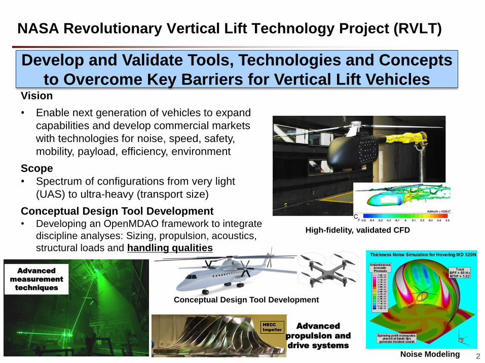
NASA Revolutionary Vertical Lift Technology Project (RVLT)
Develop and Validate Tools, Technologies and Concepts
to Overcome Key Barriers for Vertical Lift VehiclesVision
• Enable next generation of vehicles to expand
capabilities and develop commercial markets
with technologies for noise, speed, safety,
mobility, payload, efficiency, environment
Scope
• Spectrum of configurations from very light
(UAS) to ultra-heavy (transport size)
Conceptual Design Tool Development• Developing an OpenMDAO framework to integrate
discipline analyses: Sizing, propulsion, acoustics,
structural loads and handling qualities
2
Conceptual Design Tool Development
Noise Modeling
High-fidelity, validated CFD
Advanced
propulsion and
drive systems
Advanced
measurement
techniques
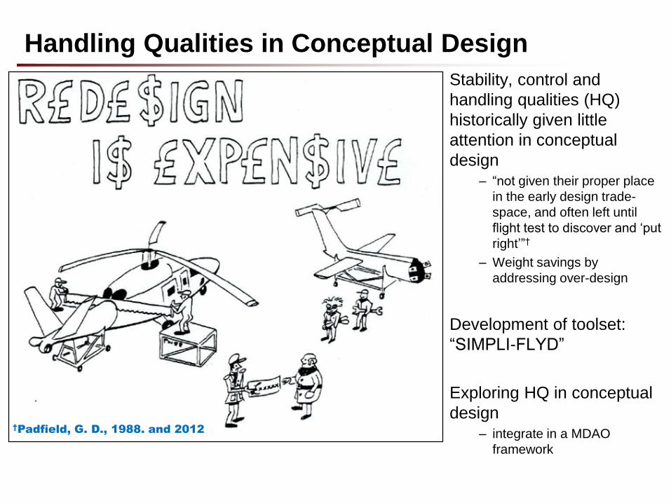
Stability, control and
handling qualities (HQ)
historically given little
attention in conceptual
design – “not given their proper place
in the early design trade-
space, and often left until
flight test to discover and ‘put
right’”†
– Weight savings by
addressing over-design
Development of toolset:
“SIMPLI-FLYD”
Exploring HQ in conceptual
design– integrate in a MDAO
framework
Handling Qualities in Conceptual Design
†Padfield, G. D., 1988. and 2012
• SIMPLI-FLYD
– CONDUIT optimization and HQ design margins
• NDARC/SIMPLI-FLYD coupling
• Results
– Tiltrotor
– Helicopter
• Lessons learned
• Future developments
Contents
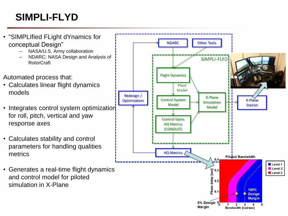
• “SIMPLIfied FLight dYnamics for
conceptual Design”– NASA/U.S. Army collaboration
– NDARC: NASA Design and Analysis of
RotorCraft
Automated process that:
• Calculates linear flight dynamics
models
• Integrates control system optimization
for roll, pitch, vertical and yaw
response axes
• Calculates stability and control
parameters for handling qualities
metrics
• Generates a real-time flight dynamics
and control model for piloted
simulation in X-Plane
SIMPLI-FLYD
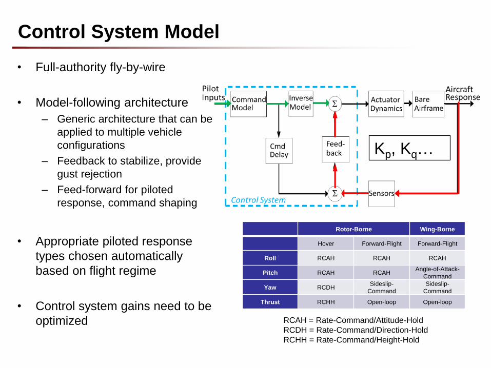
• Full-authority fly-by-wire
• Model-following architecture
– Generic architecture that can be
applied to multiple vehicle
configurations
– Feedback to stabilize, provide
gust rejection
– Feed-forward for piloted
response, command shaping
• Appropriate piloted response
types chosen automatically
based on flight regime
• Control system gains need to be
optimized
Control System Model
RCAH = Rate-Command/Attitude-Hold
RCDH = Rate-Command/Direction-Hold
RCHH = Rate-Command/Height-Hold
Rotor-Borne Wing-Borne
Hover Forward-Flight Forward-Flight
Roll RCAH RCAH RCAH
Pitch RCAH RCAHAngle-of-Attack-
Command
Yaw RCDHSideslip-
Command
Sideslip-
Command
Thrust RCHH Open-loop Open-loop
Kp, Kq…
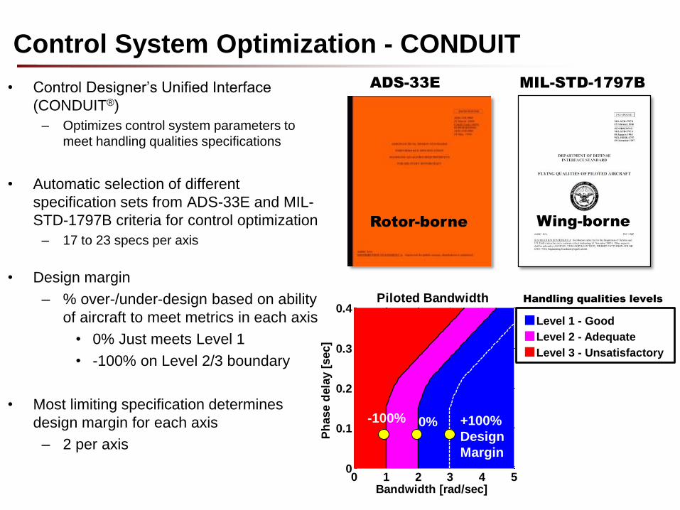
Control System Optimization - CONDUIT
• Control Designer’s Unified Interface
(CONDUIT®)
– Optimizes control system parameters to
meet handling qualities specifications
• Automatic selection of different
specification sets from ADS-33E and MIL-
STD-1797B criteria for control optimization
– 17 to 23 specs per axis
• Design margin
– % over-/under-design based on ability
of aircraft to meet metrics in each axis
• 0% Just meets Level 1
• -100% on Level 2/3 boundary
• Most limiting specification determines
design margin for each axis
– 2 per axis
ADS-33E MIL-STD-1797B
Rotor-borne Wing-borne
0 1 2 3 4 50
0.1
0.2
0.3
0.4
Bandwidth [rad/sec]
Ph
ase d
ela
y [
sec]
Piloted Bandwidth
■Level 1 - Good
■Level 2 - Adequate
■Level 3 - Unsatisfactory
0% +100%
Design
Margin
-100%
Handling qualities levels
• Evaluate NDARC/SIMPLI-FLYD coupled analysis to explore
handling qualities in conceptual design
• Example aircraft/HQ scenarios chosen:
– NDARC models with typical missions for sizing task
– Varied a mix of design and actuator parameters
• Tiltrotor pitch axis
– Forward flight only
– Varied horizontal tail size, location, flap area ratio, actuator rate limit
• Single Main Rotor (SMR) helicopter yaw axis
– Hover & forward flight
– Varied tail rotor size, location, collective actuator bandwidth and rate
limit
Objectives and example cases
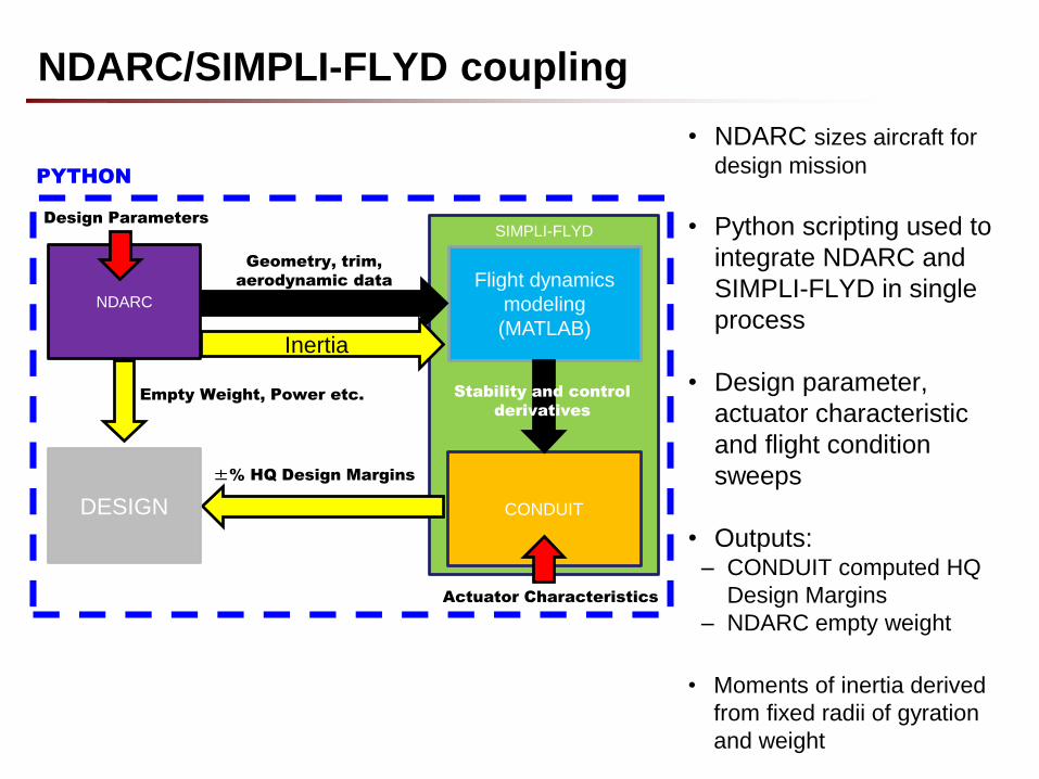
SIMPLI-FLYD
Flight dynamics
modeling
(MATLAB)
CONDUIT
Stability and control
derivatives
PYTHON
±% HQ Design Margins
DESIGN
Empty Weight, Power etc.
NDARC
Geometry, trim,
aerodynamic data
Design Parameters
Actuator Characteristics
NDARC/SIMPLI-FLYD coupling
• NDARC sizes aircraft for
design mission
• Python scripting used to
integrate NDARC and
SIMPLI-FLYD in single
process
• Design parameter,
actuator characteristic
and flight condition
sweeps
• Outputs:– CONDUIT computed HQ
Design Margins
– NDARC empty weight
• Moments of inertia derived
from fixed radii of gyration
and weight
Inertia
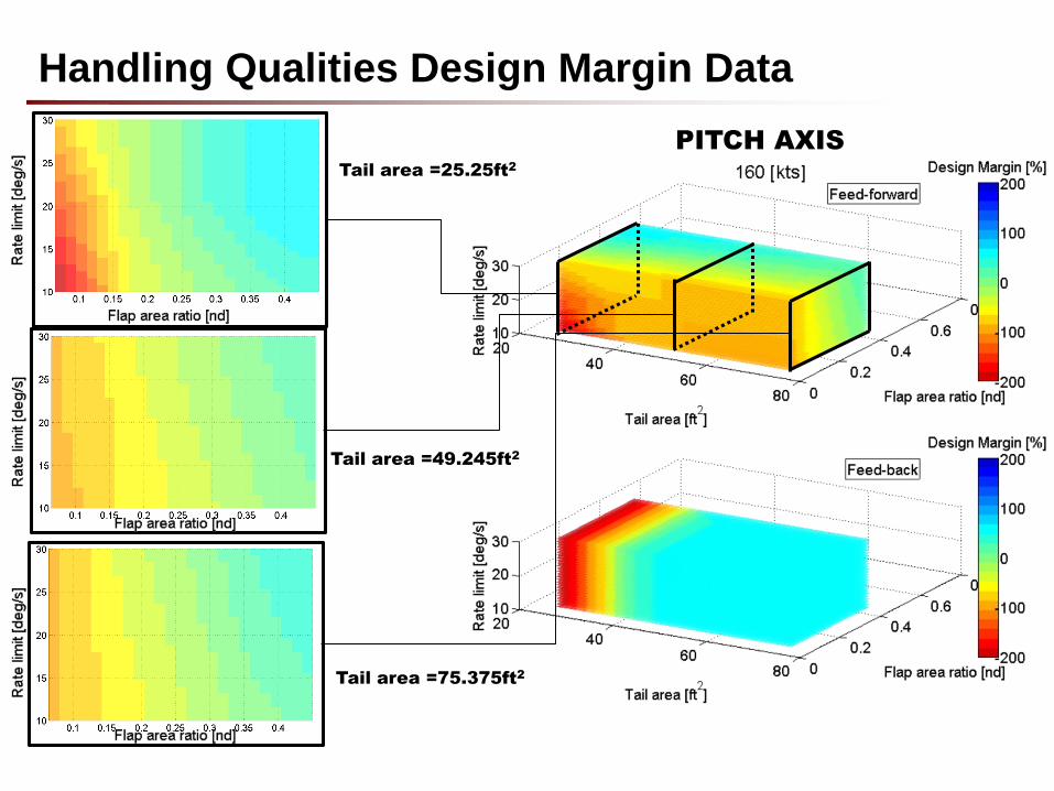
Handling Qualities Design Margin Data
PITCH AXIS
Tail area =75.375ft2
Tail area =49.245ft2
Tail area =25.25ft2
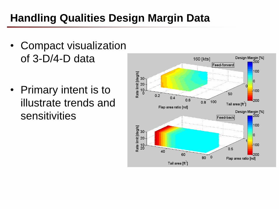
Handling Qualities Design Margin Data
• Compact visualization
of 3-D/4-D data
• Primary intent is to
illustrate trends and
sensitivities
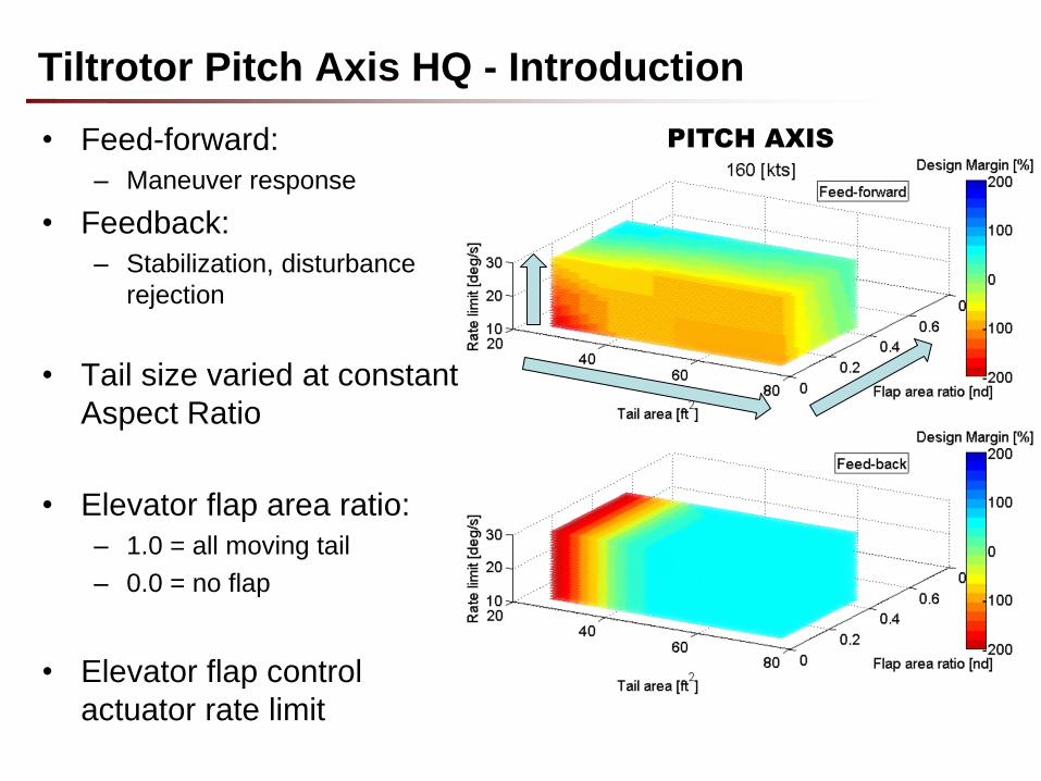
Tiltrotor Pitch Axis HQ - Introduction
• Feed-forward:
– Maneuver response
• Feedback:
– Stabilization, disturbance
rejection
• Tail size varied at constant
Aspect Ratio
• Elevator flap area ratio:
– 1.0 = all moving tail
– 0.0 = no flap
• Elevator flap control
actuator rate limit
PITCH AXIS
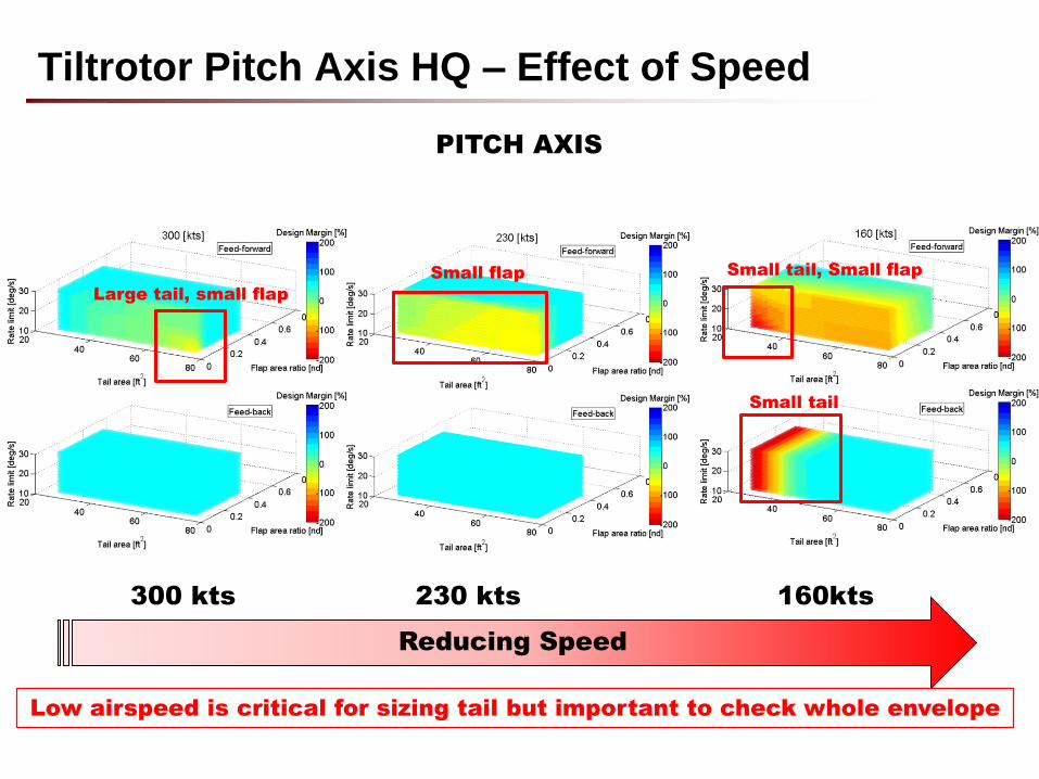
Tiltrotor Pitch Axis HQ – Effect of Speed
Reducing Speed
Large tail, small flap
Small flap Small tail, Small flap
Small tail
300 kts 230 kts 160kts
PITCH AXIS
Low airspeed is critical for sizing tail but important to check whole envelope
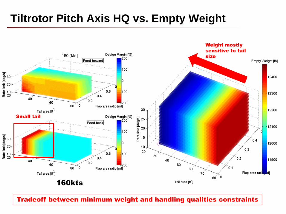
Tiltrotor Pitch Axis HQ vs. Empty Weight
Small tail
160kts
Weight mostly
sensitive to tail
size
Tradeoff between minimum weight and handling qualities constraints
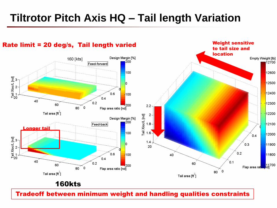
Tiltrotor Pitch Axis HQ – Tail length Variation
Longer tail
Rate limit = 20 deg/s, Tail length varied
160kts
Weight sensitive
to tail size and
location
Tradeoff between minimum weight and handling qualities constraints
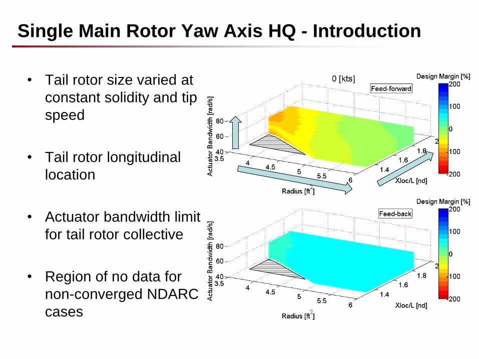
Single Main Rotor Yaw Axis HQ - Introduction
• Tail rotor size varied at
constant solidity and tip
speed
• Tail rotor longitudinal
location
• Actuator bandwidth limit
for tail rotor collective
• Region of no data for
non-converged NDARC
cases
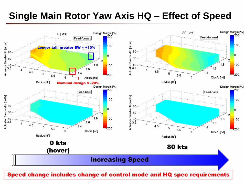
Single Main Rotor Yaw Axis HQ – Effect of Speed
Increasing Speed
0 kts
(hover)80 kts
Nominal design ≈ -20%
Longer tail, greater BW ≈ +10%
Speed change includes change of control mode and HQ spec requirements
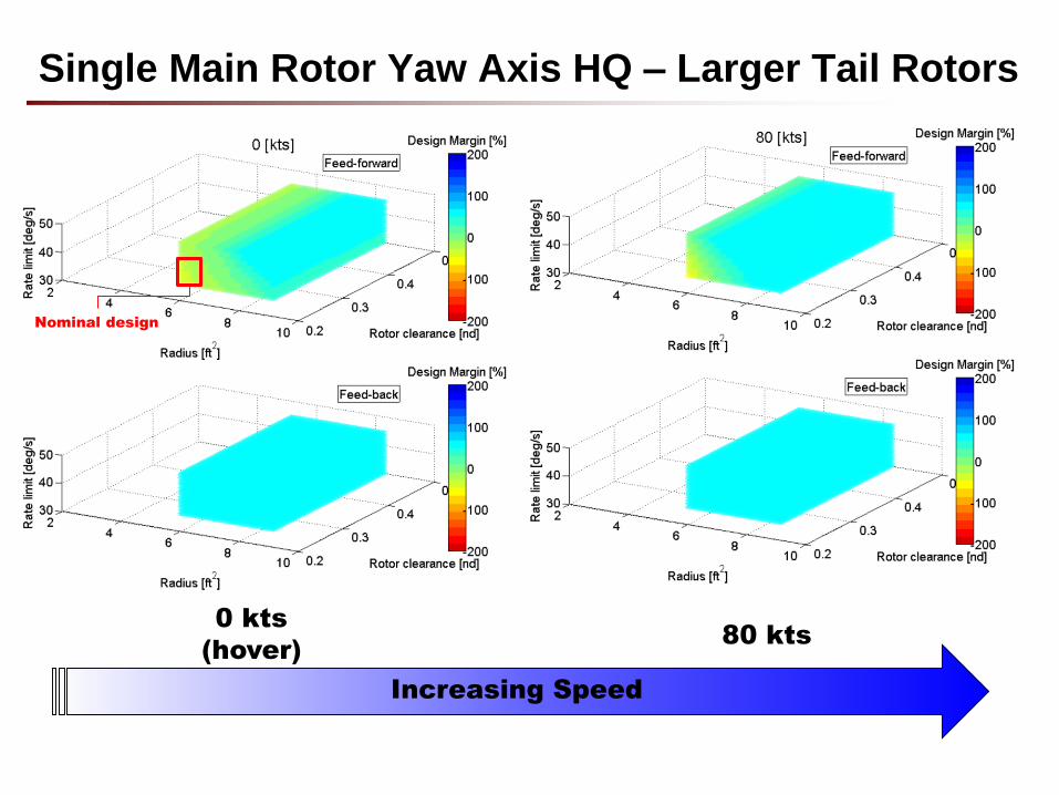
Single Main Rotor Yaw Axis HQ – Larger Tail Rotors
0 kts
(hover)80 kts
Nominal design
Increasing Speed
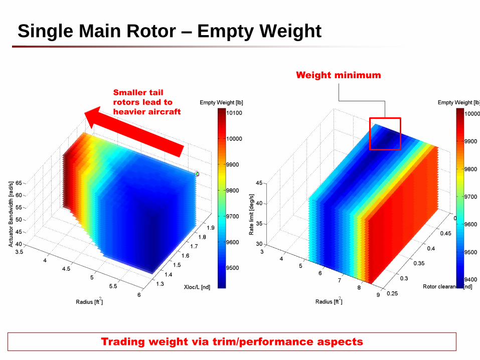
Single Main Rotor – Empty Weight
Smaller tail
rotors lead to
heavier aircraft
Weight minimum
Trading weight via trim/performance aspects
• Handling qualities vary with flight condition:
– Due to different characteristics and different HQ requirements
– CONDUIT Design Margin helps to provide a consistent metric
• Actuator characteristics important factor
– “Cost” (weight) needs to be accounted for in design
• Inertia modeling probably not sensitive enough to design
changes relevant to HQs
• Ensuring geometry “consistency” also important
• Current SIMPLI-FLYD process approx. 15-20 min per flight
condition
Lessons Learned From Application Of The Tools
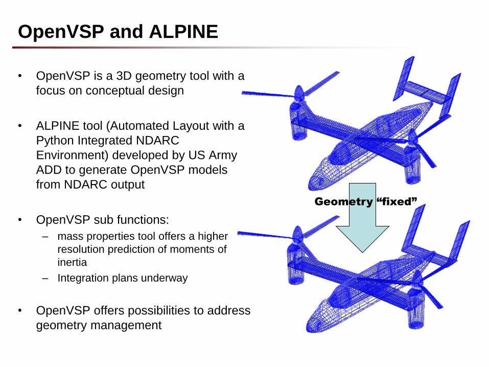
• OpenVSP is a 3D geometry tool with a
focus on conceptual design
• ALPINE tool (Automated Layout with a
Python Integrated NDARC
Environment) developed by US Army
ADD to generate OpenVSP models
from NDARC output
• OpenVSP sub functions:
– mass properties tool offers a higher
resolution prediction of moments of
inertia
– Integration plans underway
• OpenVSP offers possibilities to address
geometry management
OpenVSP and ALPINE
Geometry “fixed”
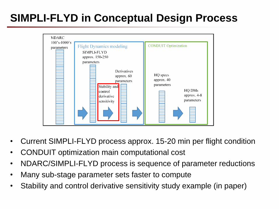
• Current SIMPLI-FLYD process approx. 15-20 min per flight condition
• CONDUIT optimization main computational cost
• NDARC/SIMPLI-FLYD process is sequence of parameter reductions
• Many sub-stage parameter sets faster to compute
• Stability and control derivative sensitivity study example (in paper)
SIMPLI-FLYD in Conceptual Design Process
• Coupled NDARC/SIMPLI-FLYD analysis to examine:
– Different vehicle types
– Mix of design parameters and flight conditions
– Different handling qualities problems
• Future Developments:
– OpenMDAO integration – tradeoffs with other disciplines
– Inertia modeling – ALPINE integration
– Actuator modeling – weight/cost, greater fidelity
– Other configurations – e.g. rotor interference
– Computational requirements – SIMPLI-FLYD role in conceptual
design
Summary

Questions?