Technology-enabled healthcare transformation: concept paper
23
1 Technology-enabled healthcare transformation: concept paper 1 Executive summary [WHY] We believe that healthcare sector needs a disruptive transformation: healthcare should be more affordable; healthcare should offer the best possible services for each patient; healthcare should become the centre of the health value-stream; healthcare should seamlessly incorporate innovations; healthcare should be secured by design; healthcare should prevent unjustified proliferation of tools. [HOW] Such a transformation is achievable by synergy among various proven modern capabilities: achievements in design of software-intensive distributed systems; architectures for pluggable agile solutions; mature enterprise-wide methodologies as Enterprise Architecture, BPM, SOA and ECM; Internet of things; free and open-source software; partnership between public, private, academic, social and voluntary sectors; sectorial, regional and international collaboration and standardisation. [WHAT] A platform-enabled reference architecture and several technological solutions implemented with this architecture will prove that: each patient can be served by knowledge and experience available world-wide hassle- free, remotely and anonymously; any treatment can be transparent in value, cost and results, justified, objectively validatable and traceable; the unique business processes of each healthcare establishment can be assembled from a common library of process patterns (fragments) and tasks thus effortlessly spreading best medical practices and proven medical knowledge; routine activities of the healthcare workers can be automated thus providing the opportunity for more added-value and innovation; the information in the healthcare can be secure stored, exchanged, analysed and enriched; new technologies, tools, devices, procedures and knowledge can be easily plugged-in thus creating opportunities for start-ups; business systems in healthcare can be constructed from components of different vendors and from various origins (borrowed, bought, built, outsourced, standardised, innovated, re-engineered) to quickly create best-to-fit configurations. 2 Architecting the technology-enabled healthcare transformation 2.1 General Architecture of a system has to provide a brief description of the important aspects of the system. Any system (enterprise, eco-system, supply-chain, industry, country, region, etc.) has
-
Upload
alexander-samarin -
Category
Technology
-
view
495 -
download
0
Transcript of Technology-enabled healthcare transformation: concept paper

1
Technology-enabled healthcare transformation: concept paper
1 Executive summary
[WHY] We believe that healthcare sector needs a disruptive transformation:
healthcare should be more affordable;
healthcare should offer the best possible services for each patient;
healthcare should become the centre of the health value-stream;
healthcare should seamlessly incorporate innovations;
healthcare should be secured by design;
healthcare should prevent unjustified proliferation of tools.
[HOW] Such a transformation is achievable by synergy among various proven modern
capabilities:
achievements in design of software-intensive distributed systems;
architectures for pluggable agile solutions;
mature enterprise-wide methodologies as Enterprise Architecture, BPM, SOA and ECM;
Internet of things;
free and open-source software;
partnership between public, private, academic, social and voluntary sectors;
sectorial, regional and international collaboration and standardisation.
[WHAT] A platform-enabled reference architecture and several technological solutions
implemented with this architecture will prove that:
each patient can be served by knowledge and experience available world-wide hassle-
free, remotely and anonymously;
any treatment can be transparent in value, cost and results, justified, objectively
validatable and traceable;
the unique business processes of each healthcare establishment can be assembled from
a common library of process patterns (fragments) and tasks thus effortlessly spreading
best medical practices and proven medical knowledge;
routine activities of the healthcare workers can be automated thus providing the
opportunity for more added-value and innovation;
the information in the healthcare can be secure stored, exchanged, analysed and
enriched;
new technologies, tools, devices, procedures and knowledge can be easily plugged-in
thus creating opportunities for start-ups;
business systems in healthcare can be constructed from components of different
vendors and from various origins (borrowed, bought, built, outsourced, standardised,
innovated, re-engineered) to quickly create best-to-fit configurations.
2 Architecting the technology-enabled healthcare
transformation
2.1 General
Architecture of a system has to provide a brief description of the important aspects of the
system. Any system (enterprise, eco-system, supply-chain, industry, country, region, etc.) has

2
many different stakeholders who see the system differently. (Further each participant of such a
system is considered as its stakeholder). Thus different aspects of the system have different
importance for different participants (also known as participant’s concerns).
For some of participants it may be the purpose of the system or customer experience. Others
may be more interested in easy evolution of the system. It is for architect to give coherent and
convincing answers to all participants how their concerns will be addresses by the system and
how their current work habits and experience will be changed for the better. Architect must to
speak to participants differently! “Success is in the eyes of beholder” is the first rule for many
architects.
This chapter provides several viewpoints (participant’s concerns) and related views (description
of the system) for the following participants:
Citizens
Patients
Healthcare professionals
Healthcare industry self-regulator
Government regulator for healthcare
Healthcare service providers
Medical research organisations
Medical equipment vendors
Health insurance companies
Architects of technology-intensive applications for healthcare
Managers of technology-intensive projects for healthcare
Some of these views are specific for healthcare; others are healthcare independent. The
following matrix shows relative importance of each view for various participants.
2.2
Big
pic
ture
2.3
Refe
rence
functional arc
hitectu
re
2.4
Ente
rprise a
s a
syste
m o
f pro
cesses
2.5
Security
enhanced
by t
he u
se o
f
pro
cesses
2.6
Som
e p
art
icip
ant’s
vie
w
2.7
Pla
tform
-based
appro
ach
2.8
Im
ple
menta
tion
pra
ctices
2.9
Pro
ject
managem
ent
pra
ctices
2.1
0 M
ulti-
layer
imple
menta
tion m
odel
2.1
1 A
gile s
olu
tion
delivery
pra
ctices
2.1
2 V
arious
technolo
gie
s a
round
2.1
3 M
odern
isation o
f
applications t
o b
ecom
e
pro
cess-c
entr
ic
Citizens +++ + +++
Patients ++ ++ +++
Professionals + +++ ++ + + + +
Self-regulator ++ ++ +++ +++ + + +
Governmental regulator
+ + ++ +++ + +
Service providers
+ +++ ++ ++ ++ + + + ++ +++ + +++
Research + ++ ++ ++
Vendors + +++ ++ +++ ++ ++ ++ ++ +++ ++ ++
Insurance +++ ++ ++ + ++ ++
Architects + ++ +++ +++ +++ ++ ++ +++ +++ +++ +++
Project managers
+ ++ +++ ++ + + ++ +++ + + + +

3
2.2 Big picture of healthcare
The big picture of the healthcare is shown in figure 1 as a value-stream for curing patients
which is continuously improved by accumulated knowledge and more sophisticated processes
and services.
Figure 1 Big picture of healthcare
The target of the technology-enabled transformation is to deploy gradually this big picture into
each participant of the healthcare to be able to share data, services, processes, knowledge,
tools and to eliminate barriers for innovations.
Figure 2 Big picture of healthcare will enable much higher level of cooperation, collaboration and coordination with the healthcare sector

4
2.3 Reference functional architecture
2.3.1 Generic
Figure 3 shows various functional (business and technical) capabilities to be provided as a
“Healthcare Platform” to support the big picture.
Figure 3 Reference functionality of the common healthcare platform
2.3.2 Healthcare-common capabilities
• Medical records
• Inter-participants secure data and information exchange
2.3.3 Healthcare domains capabilities
To be provided during the evolution of the platform.
2.3.4 Best business practices
• Knowledge management practices: business manual, QMS
• Security practices
• Risk management practices
• Compliance practices
• Governance practices
• Project management practices
• Performance practices: SLAs, KPIs, predictive analytics
• Constrains optimisation
• Customer experience practices
2.3.5 Universal business capabilities
• BRM as methodology (including The Decision Model)
• BPM as managing by processes methodology (BPM, 6sigma, lean, etc.)
• Relationship management: SRM, CRM
• Business performance reporting and analytics
• RM and archiving
• Project management methodology (PMI, Prince 2, Hermes)
• Operations documentation
• Business domain data (or biz objects) repository and model
• Business reference information
• Capability (business domain) modelling

5
• Organisation, roles and rights management
2.3.6 Specialised enterprise capabilities
• Financial accounting
• Marketing
• Legal
• Procurement
2.3.7 Basic technical capabilities (or technologies)
• Data Warehouse (as a place to re-use data)
• BRM as a technology
• BPM as a technology (managing processes per ce)
• CRM as a technology
• ECM
• Communication tools (e-mail, skype, IM)
• Social connectivity
• ESB
• Micro-service-server
• Identity and access management
• Data encryption and security
• Interactive portals: Web-based, mobile-apps-based
• Complex Event Processes (CEP)
• Technical monitoring and traceability
2.4 Enterprise as a system of processes
2.4.1 General
Enterprise functioning can be considered as business activity flows spanning the IT
applications, employees, customers and partners within and beyond the boundaries of the
enterprise. (Business activity is a unit of work). Those flows and individual business activities
within them are interrelated. The relationships between them are static (expressed as
structure) and dynamic (expressed as behaviour). The number of potential relationships
between activities is huge – N x (N-1)/2 for N activities. This is the root cause of the
complexity of modern enterprise’s.
Historically, business process is an essential business concept for bringing some order into the
structure and the behaviour of interrelated business activities. A business process is explicitly-
defined coordination for guiding the purposeful enactment of business activities. In its simplest
form, business process is an initially agreed plan to follow an order of activities; the plan may
include some variants and the plan allows some changes during its execution. A detailed,
formalised and unchangeable plan (e.g. in a form of process template expressed in BPMN) is
one of the several coordination techniques (see http://improving-bpm-
systems.blogspot.fr/2014/03/coordination-techniques-in-bpm.html ) potentially used in
business processes.
Because coordination between some activities can be strong (e.g. as in the army) or weak
(e.g. as in an amateurs football team), it is possible to discover various stable coordination
constructs (in addition to business processes. Usually, the coordination between business
activities which belong to a particular coordination construct is stronger that the coordination
between similar coordination constructs.
The knowledge about coordination constructs reduces the number of potential relationships
between business activities. This is reducing the level of complexity of an enterprise.
Let us consider 4 nested coordination constructs:
1. process patterns (coordination between activities within processes)

6
2. processes (coordination between process fragments and separate activities)
3. cluster of processes (coordination between processes)
4. system of processes (coordination between clusters of processes)
2.4.2 Process patterns
It was observed that although all business processes are unique, they are actually composed
from similar process fragments or process patterns. For example, let us consider a typical
“repair” process in housing management which comprises claim making, evaluation, selection
of a service provider, repair, control, invoicing and insurance to pay the activities. This process
is actually composed from a few process patterns as shown in figure 4 with an original process
diagram (which was developed without patterns) covered by patterns (red rectangulars).
Figure 4 Example of a process diagram with implicit use of process patterns
Patterns used in this illustration are:
Pattern SI – “Submission Interface” see http://www.slideshare.net/samarin/process-
practical-patterns-si
Pattern PAR – “Propose, Act and React” see 8.3.12 from www.samarin.biz/book
Pattern IPS – “Initial Process Skeleton” see 8.3.7 from www.samarin.biz/book
Although any pattern is a highly-cohesive construct, patterns can be adapted for particular
needs. For example, the Delegation of Authority Matrix (DAM) pattern (see http://improving-
bpm-systems.blogspot.ch/2012/07/practical-process-pattern-dam.html ) is implemented
differently in the procurement and in the project management. Some process patterns are
available at http://improving-bpm-
systems.blogspot.fr/search/label/practical%20process%20patterns
2.4.3 Cluster of processes
Coordination between processes is usually event-based (see figure 5 with lightning symbol for
events). In the simplest variant, the finish of a process is the start of another process. Note
that it looks like the state-based coordination between processes.
Figure 5 Simple coordination between processes

7
In the reality, there are more complex interactions between processes (see figure 6) which are
described in detail in http://improving-bpm-systems.blogspot.ch/2014/03/enterprise-as-
system-of-processes.html .
Figure 6 Examples of complex coordination between processes
Processes, which are strongly related to each other, form a Cluster Of Process (CLOP). CLOPs
usually exist around functional processes which are implemented in a particular business
function, e.g. “Field Services”.
In addition to functional processes there is a set of processes (called halo of processes) which
helps to execute functional processes. These additional processes are monitoring, operating
and governance processes:
Monitoring processes are responsible for analysing the running functional processes –
some sort of operational intelligence.
Operating processes are used for implementing operational (via available parameters or
controls) changes.
Governance processes are used for detecting, designing and implementation of struc-
tural changes, e.g. “customer satisfaction and loyalty development”, “quality”, “strategy
and planning” etc.
All together (see figure 7) additional processes constitute two control loops – operational and
strategic.
Figure 7 Cluster of processes and its halo

8
2.4.4 Coordination between CLOPs
Each CLOP may relate to the enabling group of clusters, the supporting group of clusters and
the customer group of clusters (see figure 8). The enabling group of clusters are typically
specific for a particular CLOP while the supporting group of clusters are common for several
CLOPs.
Figure 7 Coordination between CLOPs
Value streams and end-to-end enterprise processes are usually formed from a few CLOPs.
2.5 Enhancing information cecurity by the use of processes
2.5.1 General
Ensuring of the information security implies the following characteristics of the enterprise
functioning:
1. Any business activity is performed only as prescribed and any unintended use of
information (e.g., access to information resources unrelated to the work performed)
would be impossible in principle.
2. Initial planning of business activities must be validated for the compliance with the
formal rules of information security.
3. Execution and operational planning of business activities must be constantly validated
for the compliance with the formal rules of information security.
4. The explicit coordination of business activities allows synchronising them with security
and risk related activities.
2.5.2 Control of access to an informational resource along its life-cycle
In simple cases, the control of access to an informational resource can be rigidly connected to
the phases of the life cycle of the resource. The latter can be implemented as a business
process. Explicit and executable business process is convenient because the whole dynamic of
control access is embedded in the process. This allows better control of access rights change
(as shown in figure 8).
Figure 8 Evolution of access right during the life-cycle

9
2.5.3 Control of access to an informational resource at activity level
In more complex cases, information resources are linked to specific business activities. An
employee, appointed for the carrying out of a particular business activity, gets access to the
information resources required for the carrying out this business activity, only for the duration
of this business activity (as shown in figure 9).
Figure 9 Evolution of access right around a business activity
Objective operational data collected, who has/had access to what information resources will
increase the level of information security. Thus, business processes can detect potential cases
for the separation of duty by establishing relationships between business activities.
2.5.4 Separation and imposition of duty among several business processes
In general, security-related relationships between business activities should be established and
formally registered. A non-inclusive list of such relationships is the following:
Other activities which validate the results of the given activity.
Other activities which define the governance for the given activity.
Other activities which do the handling exceptional situations for the given activity (error
handling, escalations, send for review and delegate).
Other activities which audit the given activity (1st, 2nd and 3rd party audit).
Other activities which evaluate the risks before the given activity.
Other activities which evaluate the risks after the given activity.
Other activities which certify the given activity (1st, 2nd and 3rd party certification).
Other activities which do compensation (undo) for the given activity.
These relationships between activities define some limitations that roles and actors may carry
out what activities: the same actor or a different actor from a different role or a different actor
from the same role. For example, if the “Activity_B” validates the results of “Activity_A” then
no actor should be in “Role_1” and “Role_2” simultaneously (as shown in figure 10).
Figure 10 Separation of duties among several business processes
Thus, the separation of duty may be formally validated at the design-time.
2.5.5 Management of risk along business processes
Managing any work by processes allows addressing the risk-related issues in proactive
manner. The risk is strongly related to how the business processes are carried out. By

10
understanding processes (i.e. through being able to simulate them) the business may predict
how the risk may changing during the execution of that process. The explicit description of
processes permits to add a few “check-points” within any process to examine its risk-related
“health”.
Business processes act as a skeleton to which the enterprise adds risk management activities
(as shown in figure 11) – each business activity is enriched by risk-related monitoring and
evaluation.
Figure 11 Enhancing processes by risk management
The risk evaluation may initiate some risk mitigation processes. The risk evaluation may be as
complex as necessary, and it may include simulations and the conduct of statistical and
scenario analysis.
2.5.6 The intra-participants secure integration
Healthcare platform, which acts also an inter-participants coordination tool, ultimately resolved
the integration problems within the healthcare. Instead of that participants are connected to
each other in ad-hoc way, the healthcare platform offers an integration process which delivers
data and documents between all participants in a systematic way as shown in figure 12. It is
actually a centralised service (backbone) for the inter-participants secure electronic exchange
(like sending / receiving registered letters).
Figure 12 Reducing complexity in integration between participants
Generally, the backbone is decoupled from participant internal applications through two
adapters: dispatcher (handle messages coming from the backbone) and expediter (handle
messages going to the backbone). To be transmitted through the backbone, each message
(business data and documents) is protected by three "envelopes" (marked by blue circled
number in figure 13):
Business (processing) envelope
Delivery (addressing) envelope
Transportation (routing) envelope

11
Figure 13 Integration process between participants
2.6 Some participant’s view
For some participants, the healthcare platform should look like a social collaborative extranet
which may have the following visual design (see figure 14).
Figure 14 Healthcare platform as a social collaborative extranet for some participants
This extranet considers that:
Each participant has several roles, e.g. YOURSELF (person and his/her legal
representatives), MERICARED (person with insurance), PATIENT, SENIOR (persons with
age over 60 years), etc.
Person may select which roles he/she is carrying out at a particular moment in time.
Each communication between a participant and the healthcare services is a case with
associated documents, data, audit trails, records, service level agreements and key
performance indicators. A case may be completed or on-going.
2.7 Platform-based approach for working and advancing
together
How is it possible to deliver many similar capabilities for a number of highly diverse
participants in a rational way? The current way of provisioning via monolith and proprietary IT
applications leads to many duplications. At the result, we, the patients and citizens, are paying
several times for the same functionality (which often is implemented not with the highest
quality).
The big picture for healthcare is too big for one project and needs to be implemented in an
incremental way as a set of inter-related projects. In such a situation, developing the final
requirements is virtually impossible because no one does know exactly what should be built,
and, often, new functionalities should be demonstrated before articulating in detail what is
wanted. Furthermore, all participants will usually advance at own, often different, speed. If all
participants are treated in an identical manner, then the slowest determines the speed of all.

12
The traditional approach for IT application development does not work in such a case because
it requires everything to be defined up front. The pure agile approach for IT application
development does not work either because it cannot guarantee that a particular functionality
will be developed once only and systematically re-used in all applications.
Therefore, implementation approach of the big picture must enable gradual, economic and
self-accelerating of technical and business transformations for all healthcare service providers
together. Figure 15 shows a platform-based architectural approach: all common functionalities
should constitute a single platform and individual new solutions are built using the
functionalities available from the platform. The provisioning of solutions will be carried out
incrementally with the pace of a particular set of participants (or target community). At each
moment in time, each healthcare service provider may have a different pace and need a
different individual set of functionality.
Figure 15 Platform-based approach
The platform-based architectural approach is based on the following considerations:
The platform must standardise and simplify core components of the future industry-
wide system of systems. For any component outside the platform, new opportunities
should be explored using agile principles. These twin approaches should be mutually
reinforcing: the platform frees up resource to focus on new opportunities while
successful agile innovations are rapidly scaled up when incorporated into the platform.
An agile approach requires coordination at an industry level.
To minimise duplication of effort in solving the same problems, there needs to be
industry-wide transparency of agile initiatives.
Existing components of the platform need periodic review. Transparency and the
publication openly of feedback and the results of experiments will help to keep the
pressure on the platform for continual improvement as well as short-term cost savings.
An example of the platform-based approach: Android and iOS are platforms with many small
applications.
2.8 Platform implementation practices
Considering that the platform is intended for all healthcare service providers, but how is it
possible to achieve some degree of uniformity among all healthcare service providers if they
have different abilities to absorb the benefits of information technologies. Computerisation is a
journey, and each healthcare service provider needs to be allowed to adopt a suitable pace for
itself, but we also need to maintain coherence in the progression of the whole set. The use of a
“ladder” model can be useful since it permits progression of each entity in a stepwise manner
but at the same time guides the overall progression in a coherent manner. Design the “ladder”
to have a few levels of capability from “not able” to “fully capable”. Entities are permitted to
advance at different paces in their ascent to the top of the “ladder”. For example, their
progress could be planned as in figure 16.

13
Figure 16 Example of planned progress
Intensive use of process-centric implementation with various coordination techniques thus
allowing to assemble unique healthcare service provider’s processes from standard process
fragments (patterns).
Micro-services are considered as the latest SOA outcome to deliver small units of functionality
to be assembled by executable processes.
The systematic and aligned use of business processes and micro-services bring the built-in
flexibility and adaptability.
The platform is designed to be tools-independent by standardizing data, information, interfaces
and coordination between various capabilities. This will allow to build the platform
incrementally by provisioning needed capabilities from COTS, FOSS, platform-community-
owned and in-house components. A few components may be offered for one capability as
shown in figure 17.
Figure 17 Platform composition
2.9 Project management practices
There are three primary types of projects.
1. On-going and centralised platform governance: evolution of the architecture, evolution
of technologies, evolution of features, evolution of solutions, evolution of practices and
evolution of documentation.
2. Rapid implementation of solutions as mini-projects: light specifications, quick
prototyping, consistent configuration, fast procurement, agile development and re-use
of existing tools and habits.
3. Implementation of new platform components.
The preferable project management method is archibagile which combines decomposition with
agile implementation of “understood” components (see http://improving-bpm-
systems.blogspot.ch/2014/06/different-coordination-techniques-in.html and figure 18).
14
Figure 18 Example of planned progress
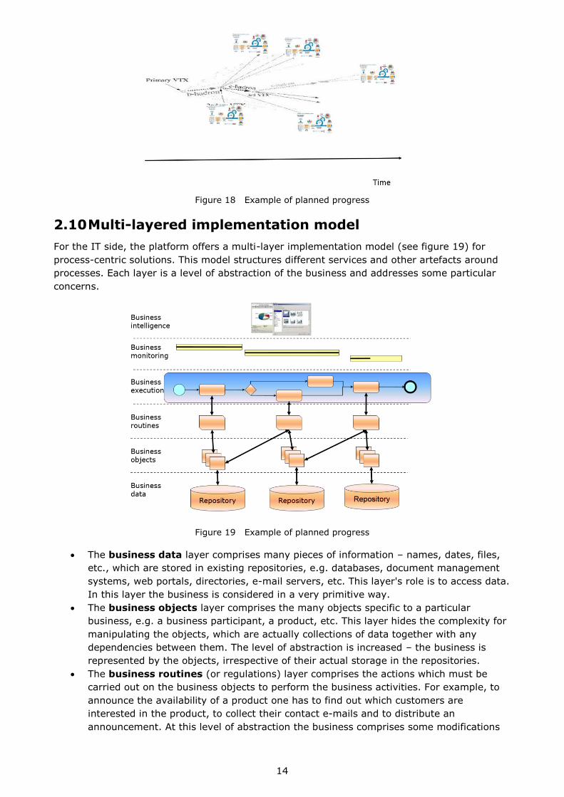
2.10 Multi-layered implementation model
For the IT side, the platform offers a multi-layer implementation model (see figure 19) for
process-centric solutions. This model structures different services and other artefacts around
processes. Each layer is a level of abstraction of the business and addresses some particular
concerns.
Figure 19 Example of planned progress
The business data layer comprises many pieces of information – names, dates, files,
etc., which are stored in existing repositories, e.g. databases, document management
systems, web portals, directories, e-mail servers, etc. This layer's role is to access data.
In this layer the business is considered in a very primitive way.
The business objects layer comprises the many objects specific to a particular
business, e.g. a business participant, a product, etc. This layer hides the complexity for
manipulating the objects, which are actually collections of data together with any
dependencies between them. The level of abstraction is increased – the business is
represented by the objects, irrespective of their actual storage in the repositories.
The business routines (or regulations) layer comprises the actions which must be
carried out on the business objects to perform the business activities. For example, to
announce the availability of a product one has to find out which customers are
interested in the product, to collect their contact e-mails and to distribute an
announcement. At this level of abstraction the business comprises some modifications

15
(including the adding of value) to the objects. Most enterprise employees work in this
layer.
The business execution layer carries out the business processes. At this level of
abstraction the business is a systematic set of coordinated activities. We can say that
this is the layer where business line managers and super-users work.
The business monitoring layer analyses the execution of the business process. The
business events are collected and compared with the expected (baseline) planning. In
addition, the behaviour of the business process can be simulated. The level of
abstraction is increased – the business is validated to run correctly. The IT buzzword
applicable to this layer is Business Activity Monitoring (BAM).
The business intelligence layer implements enterprise-wide planning, performance
evaluation and control actions applied to the business processes. At this level of
abstraction the whole enterprise business system is considered as a single functional
unit.
Each layer has two roles: it exploits the functionalities of the lower layer, and it serves the
higher layer. Each layer has a well-defined interface and its implementation is independent of
that of the others. Each layer comprises many services that can be used independently – it is
not necessary that all layers be fully implemented at the same time or even be provided in a
single project.
Another practical observation is that different layers have lifecycles of different time scales:
typical repositories have a 5- to 10-year life-span while the business requires continuous
improvement. Because of the implementation independence of the different layers, each layer
may evolve at its own pace without being hampered by the others.
As a general rule, existing applications already implement many of the business objects,
routines and processes, but usually in an unstructured way. The objects, routines and
processes are intermixed, not reusable and need to be implemented again and again. The
multi-layer implementation model is a tool which helps the enterprise to design the enterprise
business systems
in business terms, but not in terms of IT tools,
via the combination of universally accessible and interdependent building blocks,
in a structured way, and
with a high level of flexibility built-in.
Here’s a tip for how to remember the layers: Data, Objects, Routines, Execution, Monitoring,
Intelligence – DO-RE-MI.
2.11 Agile solution delivery practices
A new solution is constructed from existing services and newly developed ones; the latter may
be in different layers. Versioning of artefacts brings unprecedented flexibility, and thus
removes the existing segregation between software development and maintenance – the IT
unit can easily carry out continuous evolution of the system.
The development team members develop solutions as a set of easy-to-evolve artefacts (of
course, within the limits defined by the architects). Below there are a few examples of the
evolution of a solution constructed in accordance with the multi-layer implementation model.
To demonstrate the reuse of existing services, newly created services are marked using a star
in the top right corner. Note that the two top levels (intelligence and monitoring) have been
removed to simplify these examples.
Example 1 (see figure 20) is a process for releasing a product for customers while minimising
the amount of human activity. Automated activity a1 collects all necessary information from
internal repositories (ERP and int. DMS), and populates it into an external repository (ext.
DMS) without opening external access to it. Human activity a2 requires a person to check the
product, its metadata and other related resources to ensure that everything is in order for the

16
product to be released to the customer. Automated activity a3 opens customer access to the
product (on ext. DMS).
Figure 20 Example 1
Example 2 (see figure 21) is an extension of example 1. Automated activity a4 uses a
customer directory and prepares a notification to a customer if the released product matches
his/her interests. Automated activity a5 delivers this notification via e-mail.
Figure 21 Example 2
Example 3 (see figure 22) is a process for the handling of some external requests. Automated
activity a6 analyses the input obtained via e-mail and saves it into an internal repository (int.
DMS) for traceability purposes. If necessary, human activity a7 is executed to categorize a
request. Automated activity a8 performs any necessary actions. Automated activity a5 informs
the requestor (via an e-mail) of the actions taken.
Figure 22 Example 3

17
Example 4 (see figure 23) is a process for some typical work. Automated activity a9 fetches
information from internal repositories and prepares it for manual activity a10. Automated
activity a11 validates the work done. Automated activity a12 saves the results into internal
repositories.
Figure 23 Example 4
A “snow-ball” effect is observed – as more services and libraries become available, the
implementation of each new service is faster. Also, practically all services are actually micro-
services which are small in size and functionality. (See about micro-services
http://www.tigerteam.dk/2014/micro-services-its-not-only-the-size-that-matters-its-also-how-
you-use-them-part-1/ )
2.12 Various technologies around the implementation model
The multi-layer implementation model is the main tool for the solutions architects. It helps
them to assemble solutions, which is rather different from implementing traditional
applications:
the new solution is generally implemented across existing IT applications and
repositories;
any missing building blocks are initially implemented, by preference, in a dynamic
programming language;
• the new solution generally does not have its “own” database;
• the new solution is “outside” existing systems;
• typical concerns for BPM, SOA and IT-governance are considered together.
Where in this “architectural framework” are databases, application servers, Graphical User
Interfaces (GUIs), XML, web services and other IT gadgets? By definition, it doesn't matter.
Everything in figure 18 is considered as a service. These services can be executed inside a
single program, within many programs on a single computer, on an application server or in a
distributed environment. Services may be implemented in-house today and may be outsourced
tomorrow, or implemented manually today and automated tomorrow.
Another popular question concerns the relation of the multi-layer implementation model with
some other technologies. Figure 24 shows how various technologies work together within the
platform. Normally, some services are accessible from a portal or workplace. They “float” in an
Enterprise Service Bus (ESB). The latter is used only for service-to-service connections at the
technical level and not for business- or content- based routing logic. Obviously, we want to
keep the business logic in one place (and not dispersed in an ESB) and we also want to have
explicit coordination of services (but not magic routing by an ESB). Ideally, an ESB should be
based on a solid computing basis which can be provided by a grid, modern virtualisation
infrastructure or cloud computing.

18
Figure 24 Various technologies work together
More details about this is available in the book www.samarin.biz/book
2.13 Modernisation of applications to become process-centric
Usually, the services are “cemented” within monolithic applications which bridge GUIs,
business logic and databases. To convert them into process-centric, it is necessary to
externalise all services as shown in figure 25.
Figure 25 Technical transformation of applications
Such a technical modernisation is carried out in three steps:
Disassemble an application into services.
Improve existing services and/or add new services.
Assemble services via processes.
It is important to intermix the technical transformation with the business evolution and
combine various tactics about services: rent/borrow, buy, build, outsource, centralised vs. kept
locally, standardised, re-engineered or automated.
For complex applications (such an in-house developed legacy ERP), many of the services can
be already available on the market (see figure 26).

19
Figure 26 Technical transformation of a legacy ERP
In practically all cases the transformation must be carried-out using a step-by-step approach
via the “eclipse” pattern (see figure 27). At first, we “cover” only a tiny area of the whole
process. Usually we start with the intra-application coordination, because this part of IT is
considered as boring and not very rewarding. The first fragment of explicit coordination may
be quite primitive; it is a duplication of some existing functionality which is just eclipsed by this
process. Then we introduce more and more fragments. With time, we cover bigger and bigger
areas by explicit coordination of existing fragments.
Figure 27 Use of the “eclipse” pattern for becoming process-centric
Step by step, existing applications are transformed into services. It is recommended that such
transformations be carried out with great care. For example, at first, services should be
implemented to copy as closely as possible the existing functionality; they are optimised and
refactored only later. Modifications to applications are minimised – by preference, some
functionality is just switched off. To do this, some techniques of externalising events are
necessary to link monolith applications and processes as shown in figure 28.

20
Figure 28 Externalising events which will launch processes
3 Electronic Health Records implementation (maybe
useful for “meaningful use”)
3.1 General
www.healthit.gov defines Electronic Health Records (EHRs) as, at their simplest, digital
(computerized) versions of patients' paper charts. But EHRs, when fully up and running, are so
much more than that.
EHRs are real-time, patient-centred records. They make information available instantly,
"whenever and wherever it is needed". And they bring together in one place everything about
a patient's health. EHRs can:
Contain information about a patient's medical history, diagnoses, medications,
immunization dates, allergies, radiology images, and lab and test results
Offer access to evidence-based tools that providers can use in making decisions about a
patient's care
Automate and streamline providers' workflow
Increase organization and accuracy of patient information
Support key market changes in payer requirements and consumer expectations
One of the key features of an EHR is that it can be created, managed, and consulted by
authorized providers and staff across more than one health care organization. A single
EHR can bring together information from current and past doctors, emergency facilities,
school and workplace clinics, pharmacies, laboratories, and medical imaging facilities.
3.2 Conceptual view on EHR
Certainly, EHR is the core of majority of the healthcare IT applications and a perfect
implementation of EHR is a must. Within the healthcare platform, EHR is architected in the
following way.
A person (or his/her legal representative) is the only owner of his/her EHR. Others use
person’s EHR just temporary. Any other participants in healthcare must explicitly request some
EHR from the patient. Such a request must be executed only in the context of a
process/workflow/case in which the patient and the requestor are involved (see 2.5.3).
Conceptually, my personal EHR are kept in my personal digital data and document storage. (It
may be home-based as an appliance or cloud-based). This storage is supported by:
Inbox – my official postal box in the Internet (like postal box for a person or a
household). Note, a person may have several inbox including anonymous ones.

21
Deposit box – a short-term protected cloud space for each act as a temporary storage
for of data and documents exchange. Imagine that some paper documents were copied
and put in an envelope.
Safe box – a long-term protected cloud space for a backup copy. Imagine a personal
safe box in a Swiss bank.
Encryption services.
3.3 Example of process which uses EHR
Below is an example of how the exchange between a patient (me) and a medical office should
be carried out (keep in mind 2.5.6). The situation: I made an appointment to visit a doctor.
The doctor has indicated which my medical documents (i.e. my EHR) are necessary for this
visit. I have to send some of my medical documents before the visit. This is done in the
following way (see figure 29):
1) As part of the “visit doctor” process, I got a task to send a list of medical documents. If
there is nothing special, I approve the standard execution of the task as steps 2-6.
2) Creation a dedicated deposit box (with some protection) and copy requested documents
(with some protection).
3) A temporary link to this deposit box is generated.
4) This link is communicated to the medical office’s reception service (office2others).
5) Documents from my temporary deposit box are copied to medical office temporary de-
posit box.
6) A notification about arrival of documents appears in the medical office’s inbox.
7) A medial office employee gets a task to copy the documents from the temporary de-
posit box to the medical office internal system.
Figure 29 Exchange of document in the “visit doctor” process
Documents to be sent and deposit boxes are encrypted with short-life-time keys and
techniques of secured envelope are used as well (see 2.5.6).
If some of those documents may be offered for medical research purposed then these
documents will be anonymized by removing personal information and their encryption will be
different (just to guarantee their integrity during the transition).
3.4 EHR implementation considerations
Obviously, the mentioned above concept of EHR is an ideal state that should be approached
through several transitional states. Imagine a situation when a medial organisation has EHR
diluted somewhere in several IT applications. What can be the steps to advance to a better
EHR? A possible way forward is below:

22
1. Create a separate EHR master repository with tight security and strict audit.
2. Migrate existing EHR from existing IT applications to the EHR repository.
3. Consider step-by-step modernisation of existing IT applications by starting to
externalize some events about updating the EHR (see 2.13).
4. Link those events with “integration” processes to fetch EHR from existing IT
applications and populate the EHR repository.
5. Use the EHR repository as the master source for processes and, if possible, existing IT
applications.
6. Add more “integration” processes to exchange between your organization’s EHR master
repository and other medical organizations.
7. Add more functional processes which use the EHR master repository.
8. Discuss with the vendors of your existing IT applications about externalization of EHR.
In addition, do not forget to engage an architect into this transformation. As well as,
systematically inform patients about handling of their EHR.
4 Participants, their concerns and benefits analysis
Let us look at the whole healthcare eco-system to list all participants and their concerns as the
following.
Patients – hassle-free access to the healthcare services, correctness of treatment,
maximum as possible treatment at home, cost.
Doctors—zero routine work, access to the medical knowledge, access to medications,
traceability.
Other service providers – minimum overhead, common (with doctors) decision making.
Insuring bodies – traceability, cost of overhead, correctness of treatment.
Insurance companies – correctness of claims, correctness of treatment.
Governments – overall quality, overall cost.
Other services – easy to have business the main participants.
5 Potential innovations and their effect on
participants
## Innovation Technology-enabled
techniques
Impact
1 Medical records are safely managed and properly share among the participants
Security is compared with private banks. Well-structured data. World-wide access for patient’s data.
Comprehensiveness of personal data. Anonymous by Owner data for analysis and consultations
2 A patient can visit a doctor remotely Video conferencing. Avoid hassle for trivial
cases. Better traceability.
3 A patient can provide some simple “measurements” (pressure, temperature, sugar in blood) remotely
Smart devices and connectivity.
Systematic caring, faster alerting to prevent complex situations. Better traceability.
4 Best specialists can provide consultation to an anonymous patient and recommend him/her the best possible treatment
Video conferencing. World-wide access for patient’s data.
Improving the quality of treatment.
5 Patient is guided for home-based treatment
Predefined coordination and
Better supervising

23
alerting (e.g. for taking pills). Systematic monitoring.
6 All participants of the health-care ecosystem are electronically
interlinked: doctors, hospitals, labs, pharmacies, insurances, government agencies
Secured exchange of data.
Higher quality of data. Less overhead.
7 Other social (from governmental agencies), scientific, professional (3rd party reviewing), and commercial (express delivery)
services can be plugged-in
Standard interfaces for services in standard processes.
Cost management. Opportunities for small and local businesses.
8 The joint work of all participants is coordinated in a transparent and traceable manner.
Guaranteed audit trail. Guaranteed goal.
Early catching of problems. Continual improvement.
End of document (copyright 2014, Alexander SAMARIN, V3, 2014-07-12)