Target-Pro 2 Analyzer and Sampler - Eatonpub/@eaton/@hyd/... · 2 EATON Vickers Target-Pro 2...
16
Target-Pro 2 Analyzer and Sampler Operation Manual
-
Upload
nguyenhuong -
Category
Documents
-
view
219 -
download
0
Transcript of Target-Pro 2 Analyzer and Sampler - Eatonpub/@eaton/@hyd/... · 2 EATON Vickers Target-Pro 2...

Target-Pro 2 Analyzer and SamplerOperation Manual
Operating Precautions
Battery
• The Target-Pro 2 uses a nickel-cadmium (NiCd) battery.Charge it for at least 24 hours before first use.
• For optimum performance, fully discharge and rechargethe battery once a month: Leave the Target-Pro 2switched on until the LCD screen goes blank, then switchoff the Target-Pro 2, connect the charging adapter, andallow it to charge the battery for 24 hours.
• To prolong battery life, switch off the analyzer when it isnot in use.
Internal Cleaning
Do not clean the Target-Pro 2 or Bottle Sampler with ace-tone or other solvents that are not compatible with nitrileseals. The recommended cleaning fluid for internal flushingis mineral spirits.
2 EATON Vickers Target-Pro 2 Analyzer and Sampler Operation Manual V-PP-MC-0002-E July 2004
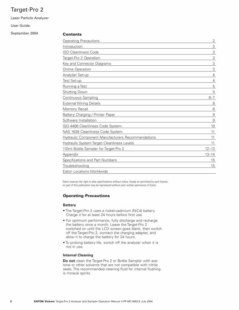
Target-Pro 2Laser Particle Analyzer
User Guide:
September 2004 Contents
Operating Precautions 2
Introduction 3
ISO Cleanliness Code 3
Target-Pro 2 Operation 3
Key and Connector Diagrams 3
Online Operation 3
Analyzer Set-up 4
Test Set-up 4
Running a Test 5
Shutting Down 5
Continuous Sampling 6–7
External Wiring Details 8
Memory Recall 8
Battery Charging / Printer Paper 9
Software Installation 9
ISO 4406 Cleanliness Code System 10
NAS 1638 Cleanliness Code System 11
Hydraulic Component Manufacturers Recommendations 11
Hydraulic System Target Cleanliness Levels 11
110ml Bottle Sampler for Target-Pro 2 12–13
Appendix 13–14
Specifications and Part Numbers 15
Troubleshooting 15
Eaton Locations Worldwide
Eaton reserves the right to alter specifications without notice. Except as permitted by such license,no part of this publication may be reproduced without prior written permission of Eaton.

3EATON Vickers Target-Pro 2 Analyzer and Sampler Operation Manual V-PP-MC-0002-E July 2004
IntroductionTarget-Pro 2 Analyzer
Operation—Online
1. Insert the waste fluid hose in the waste disposal bottleprovided.
Important: Do not connect the waste fluid hose to a pres-surized system; this will cause the analyzer to malfunctionand could cause internal leakage. Discharge the waste fluidhose into the bottle provided, or into a tank or vessel ventedto the atmosphere.
2. Connect the waste fluid hose to the waste connector porton the analyzer. Push back the quick-coupling outer ringbefore connecting or disconnecting the hose end.
3. Connect the fluid sampling hose to the HP connectoron the analyzer.
4. Connect the fluid sampling hose to the system using aminimess connector; the system to be monitored mustbe more than 2 bar and less than 400 bar.
5. Press the green button to switch on the analyzer; the‘Main/Test’ progress screen will be displayed.
Note: To improve LCD screen visibility, unlatch the twoextension feet on the case bottom and tilt the case. If LCDscreen remains blank, refer to battery charging instructions.
Next Test Reference
Next Text Number
Normal Test
ISO Code isStart Stop Print Paper Set Log Contrast
+ -
The Target-Pro 2 measures and quantifies solid contami-nants in hydraulic, lubrication and transmission applications.It is designed to provide laboratory accuracy in the field,using mineral oil as the operating fluid.
The analyzer uses the light extinction principle, in whichtwo lasers are projected through the fluid and toward photodiodes. Particles that interrupt the beams reduce the lightreceived by the diode; their sizes are measured by changesin condition.
Hydraulic and lubricating systems contain metal partsthat move continuously, with hydraulic fluid as the powermedium. The fluid also creates a lubrication film to keepprecision parts separated, and serves as a cooling medium.
By their nature, hydraulic systems produce solid particulatecontaminants. When contamination exceeds set levels,hydraulic systems can fail. A revised standard cleanlinesscode, ISO 4406, classifies the numbers of particles that canbe tolerated; the Target-Pro 2 measures the levels of thesecontaminants.
The international standard for reporting solid contaminantsis ISO 4406. This standard has been revised to incorporatethe change to ISO Medium Test Dust as the calibrationstandard.
Main/Test Progress Screen
Button1. Start—Starts sampling and emptying cycles
2. Stop—Stops test at any point (next test will start with emptying cycle before new sampling cycle begins)
3. Print—Prints a copy of test results
4. Paper—Advances printer paper by three lines
5. Set—Selects Operations Screen
6. Log—Selects software options
• Transfer Log Downloads memory to software package• Clear Log Clears memory• Clear Last Clears last result• Recall #0 Recalls results from memory• Print Prints recalled results
7. + Contrast—Increases backlight intensity
8. – Contrast—Reduces backlight intensity
Low Battery Indicator

5. Test Type—Press [5] one or more times toselect test type.
Test Types
Normal: Single test with 15ml sample volume.
Dynamic: Comprehensive triple test with results average;30ml sample volume comprising three 10ml sampling andemptying cycles. Results are displayed on completion ofthree tests, including emptying cycles.
Triple/Bottle Sampling: Triple test with results average;faster than Dynamic test; 24ml sample volume comprisingthree individual 8ml samples tested consecutively. For bottle sampling instructions, see pages 12–13.
Continuous Sampling: For instructions, see pages 6–7.
Short-Single Test: 8ml sample volume; faster than Normaltest; not recommended for oil samples cleaner than ISO17/15/12 (NAS6).
6. Test Options—Press 6 to display TestOperations screen.
Test Operations Screen (continuous test only)
These options only apply to the Continuous Test; ignore ifother test types are selected. For detailed continuous sam-pling instructions, see pages 6–7.
4 EATON Vickers Target-Pro 2 Analyzer and Sampler Operation Manual V-PP-MC-0002-E July 2004
Test Set-up
1) Minutes Between Tests:2) ISO Target Level:3) NAS Target Class:4) Do Not Log Every Test:5) Confirm Cleanliness Level
Press a Key to Choose or 0 to Exit
Press the Set button [5] to program the analyzer.The display will show the Operations Screen.
To change analyzer settings, follow this sequence:
1. Test Reference—Press [1], enter your referencedetails (up to 16 characters), and press [Return]
2. Test Number—Press [2], enter a number, and press [Return] (test numbers increase automatically)
3. Time and Date—Press [3], set time and date using key-pad, and press [Return]
A cumulative cycle count is displayed on the Time andDate screen; this value increases automatically by 1 eachtime a test is taken, and cannot be adjusted or reset.
4. Result Presentation Option—Press [4], thenpress keys to select options: Press the relevantkey to switch between option selections:
1) ISO format, Repeat 1) NAS format
2) Print detailed counts, Repeat 2) Do not print detailed counts
3) Print test reference, Repeat 3) Do not print test reference
4) Automatically print results, Repeat 4) Do not automatically print results
5) Print space for notes, Repeat 5) Do not print spacesfor notes
6. Language number (four options):
Language 0 (default) . . . . . .English
Language 1 . . . . . . . . . . . . .Italian
Language 2 . . . . . . . . . . . . .French
Language 3 . . . . . . . . . . . . .German
To select language, press 6, enter chosen value (such as1 for Italian), and press Return; to use a newly selectedlanguage, you must switch the analyzer off and on again.
1) Test Ref:2) Test Number:3) Time and Date:4) Result Presentation Options:5) Type Test:6) Test Options:
Press a Key to Choose or 0 to Exit
Operations Screen
Test Operations Screen
Analyzer Set-up

5EATON Vickers Target-Pro 2 Analyzer and Sampler Operation Manual V-PP-MC-0002-E July 2004
Analyzer UpperContamination Limit
The analyzer upper operatinglimit is set at 24/22/20.
Tests that result in particlecounts exceeding any scalenumber in the three-part ISOupper limit has the scalenumber replaced by anasterisk. Associated particlecounts on the printout arereplaced by X’s. See example.
Further Test—SameSampling Point
To repeat a test on the samesample point, press theStart button [1]. The testnumber will increase auto-matically.
Further Test—DifferentSampling Point/SameSystem
Repeat steps 7–12 above. Tochange test reference/testmode data, repeat steps1–12 on pages 4–5.
Further Test—NewSystem
Repeat steps 1 through 12on pages 4–5.
Online—NormalParticle count and ISO Code to 4406 standard (NAS Code 1638 displayed)
Online—DynamicISO and NAS codes, complete with aver-age analysis
Online—NormalParticle counts displayed; NAS Code 1638standard (ISO Code 4406 displayed)
Running a Test
Taking a Sample—Normal, Dynamic,Triple/Bottle, Short
7. Press the flush valve push-button to open the flushvalve; pushbutton lights upto indicate valve is open.
• Leave valve open for atleast one minute or 200mlof fluid; this removestrapped air and fluid fromthe previous test and elimi-nates cross-contaminationbetween samples.
8. Press the flush valve push-button to close the flushvalve; pushbutton lightgoes off.
• Alternate method: Proceedto step 9—pressing thestart button automaticallycloses the flush valvebefore sampling begins.
9. Press the startbutton [1]. Theanalyzer willbegin the sam-pling cycle.
10. Results will be automati-cally displayed on thescreen and, if Auto Printmode is on, will be auto-matically printed at theend of the sampling cycle.(If Auto Print is off, pressthe Print key for a copy ofthe printed results.)
11. After displaying theresults, the analyzer auto-matically discharges thesample fluid to waste.Test status is shown asEmptying.
12. When the Sampling andEmptying cycles are com-pleted, the test status isshown as Idle.
Results are automaticallystored to memory. Todownload, follow theinstructions on page 9.
Shutting Down
1. Press red button to switchoff analyzer.
2. Disconnect minimess con-nector on sampling hoseto isolate fluid supply.
3. Remove fluid samplinghose from analyzer.
4. Remove waste fluid hosefrom analyzer.
5. Replace end caps onsampling hose; wipeclean and store.
6. Connect waste fluid hosequick-coupling end fittingstogether; wipe clean andstore.
Interpreting Results
See page 11 for hydrauliccomponent manufacturers’recommendations on stan-dard cleanliness require-ments for various applica-tions.ISO 4406 and NAS 1638 are not directlycomparative. Please refer to page 11.

6 EATON Vickers Target-Pro 2 Analyzer and Sampler Operation Manual V-PP-MC-0002-E July 2004
Continuous Sampling—Set Intervals
The analyzer can run continuous tests at set time intervals.
Once continuous sampling has started, the flush valveopens and closes automatically before each test. This letsfluid reach the sensing arrangement before the 15ml sam-pling test begins.
The flush valve automatically opens at the end of the sam-pling cycle and remains open while the analyzer is emptyingthe sample fluid from the previous test.
Depending on the time set for minutes between tests, theflush valve operates as follows:
Time set to 0:
At the end of the emptying cycle, the flush valve automati-cally closes and the next sampling test begins immediately.
Time set between 1 and 5:
After the emptying cycle ends, the flush valve remains openfor the time set, then closes automatically before the nextsampling test.
Time set between 6 and 30000:
Flush valve automatically closes after the emptying cycleends, and remains closed until 5 minutes before the nextsample test is programmed to begin.
Notes:
When the flush valve pushbutton is lighted, the valve isopen; when the pushbutton light is off, the valve is closed.
The flush valve servo motor makes a slight ‘ticking’ noise,whether the valve is open or closed. This is normal.
Do not connect the waste fluid hose to a pressurized sys-tem; this will cause the analyzer to malfunction and couldcause internal leakage. Discharge the waste fluid hose intothe bottle provided, or into a tank or vessel vented to theatmosphere.
To conserve battery life, connect the analyzer to the poweradapter for continuous operation.
Continuous Sampling—Basic Operation
1. Follow instructions 1–5 on page 4 to selectanalyzer settings. On the Operations Screen,press [5] until Continuous is selected.
2. Test Options—Press [6], then press the rele-vant key to switch between option selections:
1. Set minutes between tests: Press [1], enter the time inminutes required between tests (value must be between 1and 30000), and press [Return].
2. Set ISO Target Level: Press [2], enter 0 (zero), and press[Return].
3. Set NAS Target Level: Press [3], enter 0 (zero), and press[Return].
4. Set logging: Press [4] once to log every test, repeat; press[4] again to deselect logging.
Note: If you deselect log every test, the analyzer will not storeany test results in its memory.
3. Press the flush valve pushbutton to open the valve; thepushbutton will light up. Leave the valve open for at least 1minute or 200ml of fluid—more if the HP sampling hose islonger than 1.5m.
4. Press the flush valve pushbutton to close the valve; thepushbutton light will go off.
Alternate method: Proceed to step 5—pressingthe start button [1] automatically closes the flushvalve before sampling begins.
5. Press the start button [1].The analyzer willbegin the sampling cycle.
6. The completion progress bar indicates test status:
Results will be displayed automatically on the screen; ifauto print mode is on, results will be automatically printedat the end of the sampling cycle; if auto print is off, pressthe print key for a copy of the printed results.
7. Between tests, status will show Waiting.
8. Press the stop button [2] at any point in the cycle to endcontinuous sampling. Test status will show Idle.
ContinuousSampling

7EATON Vickers Target-Pro 2 Analyzer and Sampler Operation Manual V-PP-MC-0002-E July 2004
Continuous Sampling—with Target Cleanliness Level
This mode is similar to basic operation, exceptthat when a specified target cleanliness level isachieved, the analyzer stops testing and the teststatus shows Completed.
9. Follow instructions 1–5 on page 4 to select analyzer set-tings. On the Operations screen, press [5] untilContinuous is selected.
10. Test Options—Press [6], then press the relevant key toswitch between option selections:
1) Set minutes between tests: Press [1], enter the timein minutes required between tests (value must bebetween 1 and 30000), and press [Return].
2) Set ISO Target Level: Press [2], enter the desiredTarget Cleanliness Level using the formatNumber/Number/Number with any code combinationfrom 5 to 24, such as 10/9/5); then press [Return].
• For continuous testing until the ISO Code is achieved,select ISO Format as described in Operating theAnalyzer, step 4. Testing will continue until all three num-bers in the code are reached.
3) Set NAS Target Level: Press [3], enter the desiredTarget Cleanliness Level as a single class number from 2 to 12, and press [Return].
For continuous testing until the NAS Class is achieved,select NAS Format as described in Operating theAnalyzer, step 4.
Testing will continue until the class number is reached ateach of the five micron size ranges covered by NAS1638.
4) Set logging: Press [4] once to log every test, repeat;press [4] again to deselect logging.
Note: If you deselect log every test, the analyzer will onlystore the test results when the Target Cleanliness Level isachieved; this reduces memory storage demands.
5) Confirm cleanliness: Press [5] once to confirm cleanliness level, repeat; press [5] again to deselect confirmation.
Note: If you select Confirm Cleanliness Level, the analyzerwill repeat the sampling cycle until the target cleanlinesslevel is reached in two consecutive samples, and will thendisplay Completed status. If you choose not to confirm thecleanliness level, the analyzer will stop, and the display willshow Completed status, after the target cleanliness level isreached only once.
Press the flush valve pushbutton to open the valve; thepushbutton will light up. Leave valve open for at least oneminute or 200ml of fluid; this removes trapped air and fluidfrom the previous test and eliminates cross-contaminationbetween samples.
11. Press the flush valve pushbutton to close the valve;the pushbutton light will go off.
Alternate method: Proceed to step 12—pressingthe start button [1] automatically closes the flushvalve before sampling begins.
12. Press the start button [1]. The analyzer willbegin the sampling cycles.
13. The completion progress bar indicates test status.
14. Results will be displayed automatically on the screen; ifauto print mode is on, results will be automatically print-ed at the end of the emptying cycle.
15. Status shows Waiting between tests.
16. Press the stop button [2] at any point in the cycle toend continuous sampling. Test status will show Idle.

8 EATON Vickers Target-Pro 2 Analyzer and Sampler Operation Manual V-PP-MC-0002-E July 2004
110ml Bottle Sampler is designedfor use with the Target-Pro 2Analyzer. The bottle samplerallows users to test fluids in situa-tions where the analyzer cannotbe connected directly to thehydraulic circuit. This helps over-come limits of time and distance,extending testing capabilities toall equipment and locations. Thisunit accepts both 100ml and110ml bottles.
The bottle sampler offers theoption of de-aerating fluid sam-ples before testing with the ana-lyzer by applying a vacuum to thechamber holding the sample bot-tle. The de-aeration feature is onlyneeded when it is suspected, orobvious, that air is present in thefluid sample.
Two cap types are supplied withthe bottle sampler: a blank vacu-um cap for use when de-aeratingfluid, and a pressure cap with ananti-vacuum valve for use whendelivering a fluid sample to theanalyzer.
Using the Bottle Sampling Unit
1. Clean the pump and hose provided with an appropriatesolvent, such as mineral spirits, before taking a sample.Do not use acetone. Clean sample bottles and associatedproducts following the instructions on page 13.
2. Draw at least 80ml of fluid from the system into the bot-tle provided. If necessary, use a hand pump.
3. Insert the waste fluid hose in the waste disposablebottle provided.
4. Connect the waste fluid hose to the waste connectoron the Target-Pro 2. If you are using a hand pump, dis-charge fluid from the hand pump into the sample bottle.
5. Place the sample bottle into the bottle sampling unit.
6. Connect the bottle sampling unit to the 12-volt DCpower supply.
If the collected fluid contains air, follow steps 7–10 to de-aerate the sample. Otherwise, skip to step 11.
Using the De-aeration Option
7. Fit the vacuum cap to the bottle sampling unit.
8. Switch off the bottle sampling unit, then turn the selector knob from Sample to Vacuum; the intermedi-ate position has no function.
9. Switch on the bottle sampling unit and leave it runningfor several minutes, until all air bubbles have beenremoved from the fluid sample.
10. Switch off the bottle sampling unit; this automaticallyvents the chamber to the atmosphere.
110ml Bottle Samplerfor Target-Pro 2

9EATON Vickers Target-Pro 2 Analyzer and Sampler Operation Manual V-PP-MC-0002-E July 2004
Operation with the Target-Pro 2
11. Fit a new disposable tube into the pressure cap, andfit the cap to the bottle sampling unit.
12. Connect the 0.5m fluid sampling hose to the bottlesampling connection.
13. Connect the fluid sampling hose to the HP connectionon the analyzer.
14. Switch on the analyzer.
15. Press the set button [5] on the Main/TestProgress Screen to select the Triple orBottle sampling option.
16. Enter test details as described on page 4.
17. Turn the selector knob to Sample.
18. Switch on the bottle sampling unit.
19. Press the flush valve pushbutton to open theflush valve for 10 seconds.
20. Press the start button [1] to begin testing.
The bottle sampling test is a three-test analysis; seepage 4 for details.
21. When the test is finished, switch off the bottle samplingunit; it will automatically vent the pressurized chamberto the atmosphere.
22. Switch off the analyzer.
Sample Bottle Cleaning Procedure
Use qualifying and controlling methods that conform to ISO3372 for sampling containers. If compliant procedures arenot possible, follow these guidelines at a minimum:
1. Half-fill the sampling bottle with the fluid to be analyzed.
2. Re-cap the bottle and shake it vigorously for 30 seconds.
3. Discard the fluid, following current COSHH legislation.
4. Repeat steps 1–3 twice, for a total of three cycles. Thefourth time the bottle is filled, analyze the sample.
Alarm/Indication Switchingduring Continuous Operation
The Target-Pro 2 can be wired to anexternal alarm to indicate testingstatus during continuous sampling.It incorporates two solid-state relays,shown in these diagrams.
Each relay is designed for a maximumcurrent of 1 amp at 24 volts nominalAC or DC (absolute maximum 60 voltpeak). Operation above these limitswill cause irreparable damage to therelays. Eaton strongly recommendsusing wire of at least 20 AWG, andinstalling a fuse between thecustomer circuit and the Target-Pro 2.
External Wiring Details
Example 2: Bulb switches on during sampling, and off when target cleanliness level isachieved (completed status). Relay 1 is also switched during Normal, Dynamic & Triplebottle test types. Relay will open at test end or when stop button is pressed.
Example 1: Bulb stays off during sampling, and switches on when target cleanlinesslevel is reached (completed status).
Note: An external signal, such as a monitoring light, buzzer or bell, is not necessary for continuous sampling.Use of this annunciator circuit is optional.

10 EATON Vickers Target-Pro 2 Analyzer and Sampler Operation Manual V-PP-MC-0002-E July 2004
Install software Pt. No. Target-Pro 2-W-30 on a suitable PCrunning Windows 95®/NT 4.0 or better. Follow instructionsfrom the Target-Pro 2-View User Manual.
Results Download
1. Connect RS232 cable to analyzer and serial port on PC.
2. Switch the analyzer on.
3. Switch PC on.
Launch Target-Pro 2-View software.From the File menu, select Upload.Data Transfer Screen will be displayed.Transfer Data.
4. Select log function from Analyzer Main/TestProgress Screen [6].
5. Press Transfer Log [1].
The analyzer will download all stored results frommemory to the software. After downloading, theanalyzer’s memory can be deleted. (select thisoption from the PC menu.)
6. When the transfer is complete, switch the analyzer off.
Software Installation
The internal battery can sustain 8 hours of continuous oper-ation (approximately 100 tests) after charging for 24 hours. Ifthe battery becomes completely discharged, charge it for atleast 15 minutes before starting a test. The analyzer mustremain connected to the power adapter until the battery hashad time to recharge.
To recharge the battery, connect the lead from the poweradapter to the DC power input socket on the analyzer. Makesure the battery charging indicator on the analyzer lights up.
Low Battery Level Indicator
When the low battery level indicator flasheson the LCD display, recharge the battery assoon as possible.
Important: Before recharging the battery, always press thered button to switch off the analyzer.
Conserving Battery Power
To help extend battery run time, use the power adapterwhenever possible. You can also save battery power byswitching the analyzer off between samples, and by turning off the Auto Print mode. The LCD screen backlightdims automatically when the external power supply is not connected.
Battery Charging
Press the log button [6] to retrieve results storedin the analyzer’s memory; the Log Screen will bedisplayed.
To view memory contents, follow these steps:
Select Recall #0 button [4] and enter the numberof the test to be retrieved.
If you do not know the test number,enter the last test number and scrollthrough the list using Next [+] orPrevious [–] to find the test you want toreview.
To print the result, press the quit button[0], then press button [5]. A copy of theresult will be printed.
Note: The result will be printed in theformat last selected through the Set function.
1) Transfer Log2) Clear Log3) Clear Last4) Recall #05) Print
Press a Key to Choose or 0 to Exit
Log Screen
Memory Recall

11EATON Vickers Target-Pro 2 Analyzer and Sampler Operation Manual V-PP-MC-0002-E July 2004
To change thermal printer paper, remove the four thumb-screws securing the cover and serrated paper cutter.Thermal printer paper is sensitized on one side only, andmust be fed into the printer mechanism as shown below.
Using a finger, press down on the print head spring at pointA; tilt the print head to the open position by pulling it back atpoint B.
Feed the paper under the roller and pull the paper end outof the mechanism. Return the print head back to its normalposition by pressing on the green lever at point C. Makesure the print head spring returns to the position shownabove.
Important: Do not operate the printer without paper; doingso will damage the printer. Replace the roll when the “endof roll” indication appears on the paper.
Warranty and Recalibration
The Target-Pro 2 is guaranteed for one year after delivery.Eaton recommends you return the analyzer once each yearfor recalibration.
Printer Paper
TroubleshootingSpecifications
Problem Check
1. LCD screen remains blank after switching on
• Make sure analyzer battery is charged, or hasbeen charging for at least 15 minutes
• See if LED illuminates when power adapter isconnected to DC power input socket on analyzer
2. Unexpected results obtained from sample
• Check the fluid sampling hose connections atboth the system and analyzer ends
• Confirm that there is a free flow of fluid to theanalyzer: press the flush valve and see if fluidpasses into the waste disposal bottle Body text:
Note: If you suspect high water/aeration levels, contactEaton for advice.
Warning: If excessive system contamination is suspected,flush the analyzer using the bottle sampling unit in conjunc-tion with a suitable solvent, such as mineral spirits.Do not use acetone.
Technology Automatic Optical Particle Analyzer Laser Package Twin Laser and Twin Optical Diode
Detectors LCD display (backlit) Sensitivity >4, 6, 14, 21, 25, 38, 50, 68 µm(c), Micron
range to revised ISO 4406 StandardAccuracy/Repeatability Better than 3% typical Calibration Each unit is individually calibrated with
ISO Medium Test Dust (MTD) based onISO 11171:1999 on equipment certified byI.F.T.S.
Analysis Range ISO 8 to ISO 24 to ISO 4406 (NAS 1638-2 to 12)
Report/Print Format ISO and NAS codes, with individual particle counts as a built-in optionPrinter Fixed head thermal printer (384 dots per line)
Target-Pro 15 ml. (normal), 30 ml. (dynamic)2 Sample Volume 24 ml. (bottle sampler)
15 ml. (continuous), 8ml. (short) Operation Max. system working pressure, 400 bar;
Min. working pressure, 2 bar Viscosity Range to 400 centistokes Operating Temperature +5 to +80°C Fluid Compatibility Mineral oil and petroleum based fluids
(consult Eaton for other fluids) Typical Test Time Result in <2.5 mins. (normal test) Power Internal rechargeable battery
(AC charger) or external 12/24 volt DCpower supply
Data Storage 600 tests Computer Interface RS 232 (serial) communication port Hose Connections minimess fittings
microbore hose, 1.5 mwaste fluid hose
Dimensions Height 210mm; Depth 260mm; Width 430mm; Weight 7.6 kg
Eaton reserves the right to alter these specifications without notice.

12 EATON Vickers Target-Pro 2 Analyzer and Sampler Operation Manual V-PP-MC-0002-E July 2004
ISO standard 4406 is the preferred method of countingsolid contaminant particles in a sample. The code is con-structed from the combination of three scale numbersselected from the following table.
The first scale number represents how many particles in a milliliter sample of the fluid are larger than 4 µm(c).
The second number represents how many particles arelarger than 6 µm(c).
The third number represents how many particles are larger than 14 µm(c).
Microscope counting examines the particles differentlyfrom APCs; the code is given with two scale numbers only.These are at 5 µm and 15 µm, equivalent to the 6 µm(c) and14 µm(c) of the APCs.
ISO 4406 Cleanliness Code System
NUMBER OF PARTICLES PER ML. SCALE NO.
More Up to andThan Including2.5M - > 281.3M 2.5M 28640k 1.3M 27320k 640k 26160k 320k 2580k 160k 2440k 80k 2320k 40k 2210k 20k 215000 10k 202500 5000 191300 2500 18640 1300 17320 640 16160 320 1580 160 1440 80 1320 40 1210 20 115 10 102.5 5.0 91.3 2.5 80.64 1.3 70.32 0.64 60.16 0.32 50.08 0.16 40.04 0.08 30.02 0.04 20.01 0.02 10.0 0.01 0
Table 5: ISO 4406 Allocation of Scale Numbers
ISO 4406 Cleanliness Code Chart (with 100ml sample volume)

13EATON Vickers Target-Pro 2 Analyzer and Sampler Operation Manual V-PP-MC-0002-E July 2004
Target Cleanliness Levels
You can use cleanliness levels to establish bench-marks. If you have no component failures over aprolonged testing period, the average level meas-ured during that time may be an acceptable goal. Ifyou need to reduce equipment failures, want toincrease component life, or expect conditions tochange considerably, you can establish a higherbenchmark and use testing to help reach it.
An acceptable level of cleanliness depends onthree features: 1. the contamination sensitivity ofcomponents; 2. the operational conditions of thesystem; 3. and the required reliability and lifeexpectancy.
NAS [National Aerospace Standard]1638 Cleanliness Code System
Maximum Contamination Limits (per 100 ml)
Size Range Classes (in microns)
00 0 1 2 3 4 5 6 7 8 9 10 11 12
5–15 125 250 500 1000 2000 4000 8000 16000 32000 64000 128000 256000 512000 102400015–25 22 44 89 178 356 712 1425 2850 5700 11400 22800 45600 91200 18240025–50 4 8 16 32 63 126 253 506 1012 2025 4050 8100 16200 3240050–100 1 2 3 6 11 22 45 90 180 360 720 1440 2880 5760Over 100 0 0 1 1 2 4 8 16 32 64 128 256 512 1024
Cleanliness Code Chart (with 100mL sample volume)
Hydraulic Component Manufacturers’Recommendations
Manufacturers know the effects of contamination. Theyissue maximum permissible contamination levels, andremind users that cleaner fluids will improve performanceand increase component life. But no one has established asingle standard for the cleanliness of hydraulic fluid, in partbecause working conditions are different for any two appli-cations. As a result, even trusted sources of information oncleanliness levels give varying recommendations.
The table below should help you get started. It gives aselection of maximum contamination levels that are typical-ly issued by component manufacturers. These relate to theuse of the correct viscosity mineral fluid. An even cleanerlevel may be needed if the operation is severe, such as highfrequency fluctuations in loading, high temperature or highfailure risk.
Note: The recommendations in this table should be viewedas starting levels; adjust them as needed to reflect opera-tional experiences or user requirements.
UNIT TYPE ISO 4406 CODE
Pump Piston (slow speed, in-line) 22/20/16Piston (high speed, variable) 17/15/13Gear 19/17/15Vane 18/16/14
Motor Axial piston 18/16/13Radial piston 19/17/13Gear 20/18/15Vane 19/17/14
Valve Directional (solenoid) 20/18/15Pressure control (modulating) 19/17/14Flow control 19/17/14Check valve 20/18/15Cartridge valve 20/18/15Proportional 18/16/13Servo valve 16/14/11
Actuator 20/18/15Typical Manufacturer Recommendations for Component Cleanliness (ISO 4406)
The NAS system was developed in 1964 to define classesof contamination in aircraft components. This standard wasextended to industrial hydraulic systems simply becausenothing else existed at the time.
The coding system defines the maximum numbers permit-ted of 100ml volume at various size intervals (differentialcounts) rather than using cumulative counts as in ISO 4406.
Although the standard provides no guidance for quoting lev-els, most industrial users quote the highest code recordedin all sizes; this convention is used on the Target-Pro 2.
Contamination Level Classes according to NAS 1638(January 1964)
Each contamination class is defined by a number from 00 to12 that indicates the maximum particles per 100 ml, countedon a differential basis, in a given size bracket.
Contamination Correspondent Recommended Typical Codes Codes Filtration ApplicationsISO 4406 NAS 1638 Degree4µm(c) 6µm(c) 14µm(c) B x ≥ 20014 12 9 3 3 High precision and
laboratory servo-systems17 15 11 6 3–6 Robotic and
servo-systems18 16 13 7 10–12 Very sensitive–high
reliability systems20 18 14 9 12–15 Sensitive–reliable systems21 19 16 10 15–25 General equipment
of limited reliability23 21 18 12 25–40 Low-pressure equipment
not in continuous service

14 EATON Vickers Target-Pro 2 Analyzer and Sampler Operation Manual V-PP-MC-0002-E July 2004
Other Standards
Although ISO 4406 is used extensively in the hydraulicsindustry, other standards are occasionally required. Directcomparison is not always possible, but this table providessome estimates.
Approximate Equivalents of Contamination ClassesISO 4406 DEF.STD 05/42 [7] NAS 1638[5] SAE 749[8]
Table A Table B ISO 11218[6] 13/11/08 — — 2 —14/12/09 — — 3 015/13/10 — — 4 116/14/09 — 400F — —16/14/11 — — 5 217/15/09 400 — — —17/15/10 — 800F — —17/15/12 — — 6 318/16/10 800 — — —18/16/11 — 1,300F — —18/16/13 — — 7 419/17/11 1,300 2,000F — —19/17/14 — — 8 520/18/12 2,000 — — —20/18/13 — 4,400F — —20/18/15 — — 9 621/19/13 4,400 6,300F — —21/19/16 — — 10 —22/20/13 6,300 — — —22/20/17 — — 11 —23/12/14 15,000 — — —23/21/18 — — 12 —24/22/15 21,000 — — —25/23/17 100,000 — — —
Correlation between Particle Sizes Obtained using ACFTD and NISTCalibration MethodsParticle Size Obtained Using ACFTD SIZE (ISO 4402:1991) ISOMTD NIST (ISO 11171) sizeµm µm(c)
1 4.22 4.63 5.14 5.85 6.46 7.17 7.78 8.49 9.110 9.811 10.612 11.313 12.114 12.915 13.616 14.417 15.218 15.919 16.720 17.521 18.222 19.023 19.724 20.525 21.226 22.027 22.728 23.529 24.230 24.931 25.732 26.433 27.134 27.935 28.536 29.237 29.938 30.539 31.140 31.7
The Target-Pro 2 is calibrated with ISO Medium Test Dust (to ISO 11171).The correlation between particle sizes and the ACFTD (old standard) tothe ISOMTD (new standard) is as follows :
ACFTD <1 5 15 25 30 50* 75* 100*
ISOMTD 4 6 14 21 25 38 50 68 * To be confirmed by NIST.
This table is only a guideline. The exact relationship between ACFTD sizes and the NISTsizes may vary from instrument to instrument, depending on the characteristics of the parti-cle counter and original ACFTD calibration.
Cleanliness Codes(continued)

15EATON Vickers Target-Pro 2 Analyzer and Sampler Operation Manual V-PP-MC-0002-E July 2004
Appendix
New ISO Standard Test Dust and its effect on ISO Contamination Control Standards
For more than 25 years, the measurement of solid particlesin hydraulic fluids has depended on AC Fine Test Dust(ACFTD), a product manufactured by General Motors.ACFTD was used for calibrating Automatic Particle Counters(APCs), testing components such as oil filters, and testingthe contaminant sensitivity of hydraulic components.
The particle size distribution of ACFTD, determined using anoptical microscope, formed the basis of ISO 4402—themethod for calibrating APCs. The limitations of optical micro-scopes meant that distribution was uncertain at particlesizes smaller than 5 microns. Consistency between batcheswas also a regular concern.
After General Motors decided to stop making ACFTD, theInternational Organization for Standardization (ISO) definedrequirements for a replacement, and asked the NationalInstitute of Standards and Technology (NIST) to produce astandard, traceable reference substance. The new dust’sparticle size distribution has been accurately determinedwith the aid of scanning electron microscopes and imageanalysis techniques.
New Test Dust Benefits
The new ISO Medium Test Dust (ISOMTD) uses similarmaterials to ACFTD, but in a slightly coarser grade to reduceparticle counting errors. ISOMTD is produced to a standarddistribution and stringent quality control procedures for reli-able consistency. In addition, production of ISOMTDincludes a revised ISO APC calibration method.
The result is a controlled reference test dust with uniformparticle size distribution. It provides the traceability requiredby ISO 9000, QS9000 and similar quality management sys-tems. A procedure for determining the performance ofAPCs means the user can set minimum acceptable levels.Benefits include improved calibration techniques and proce-dures, greater particle count reproducibility with differentequipment, and more accurate and consistent filter testresults.
Effect on IndustryTHE INTRODUCTION OF ISOMTD HAS REQUIRED CHANGES TOCERTAIN ISO STANDARDS. THESE INCLUDE:
ISO 4402 1991 Hydraulic fluid powerCalibration of liquid automatic
particle counters
ISO 4406 1987 Hydraulic fluid powerCode for defining the level of
contamination by solid particles
ISO 4572 1981 Hydraulic fluid powerFiltersMulti-pass method for evaluating
filtration performance of filter elements
To prevent confusion over which standards to use, ISO isupdating 4402 to ISO 11171, and 4572 to ISO 16889. ISOstandards written for the new test dust will use a new iden-tifier, ‘(c)’. Micron sizes according to ISO 11171 will beexpressed as ‘µm(c)’ and Beta ratios according to ISO16889 will be expressed as ‘Bx(c)’, e.g. ‘B5(c)’.
In the new ISO 4406, new calibration sizes are used to givethe same cleanliness codes as the ‘old’ calibration sizes of 5and 15 microns. This will prevent the need to change sys-tem cleanliness specifications.
The proposed cleanliness codes for APCs will be formedfrom three particle counts at 4, 6 and 14 microns, with 6and 14 microns corresponding closely to the previous 5 and15 micron measurements. Users may still quote just twocounts of 6 microns and 14 microns for APCs.
Counts derived by microscope counting methods are notaffected, so the particle sizes used for microscopy, at 5 and15 microns, will remain unchanged. The only real effectusers will experience is improved particle count accuracy;there will be no change in filter performance or ISO cleanli-ness levels.
© 2003 Eaton CorporationAll Rights ReservedPrinted in USADocument No. X-XXX-XXX-XXXSupersedes X-XXX-XXX-XXXJuly 2004
Eaton14615 Lone Oak RoadEden Prairie, MN 55344USATel: 952 937-9800Fax: 952 974-7722www.hydraulics.eaton.com
EatonDr.-Reckeweg-Str. 1D-76532 Baden-BadenGermanyTel: (49) 7221 682-0Fax: (49) 7221 682-788
Eaton20 Rosamond RoadFootscrayVictoria 3011AustraliaTel: (61) 3 9319 8222Fax: (61) 3 9318 5714