Synthesis of Asynchronous Control Circuits with Automatically Generated Relative Timing Assumptions...
51
Synthesis of Asynchronous Control Circuits with Automatically Generated Relative Timing Assumptions Jordi Cortadella, University Politècnica de Catalunya Mike Kishinevsky, Intel Corporation Steven M. Burns, Intel Corporation Ken Stevens, Intel Corporation Earlier contributions: Luciano Lavagno, Alex Kondratyev, Alex Yakovlev, Alexander Taubin
-
date post
21-Dec-2015 -
Category
Documents
-
view
224 -
download
0
Transcript of Synthesis of Asynchronous Control Circuits with Automatically Generated Relative Timing Assumptions...

Synthesis of Asynchronous Control Circuits with Automatically Generated
Relative Timing Assumptions
Jordi Cortadella, University Politècnica de Catalunya
Mike Kishinevsky, Intel Corporation
Steven M. Burns, Intel Corporation
Ken Stevens, Intel Corporation
Earlier contributions: Luciano Lavagno, Alex Kondratyev, Alex Yakovlev, Alexander Taubin

Outline
• Why asynchronous
• Relative timing
• Reminder: design flow for asynchronous circuits
• Lazy transition systems
• Timing assumptions and constraints
• Automatic generation of timing assumptions
• Results

Why asynchronous?
– All high-performance “synchronous” design styles are “asynchronous in small” (within one/few clocks). Example: [ISSCC2001 Intel paper on 4GHz IEU for 0.18um CMOS in Pentium 4(tm)]. Requires asynchronous style timing analysis.
– Relative sequential distance within a die for global wires is growing
– Can we deliver global clock N years from now?

Timing assumptions in design flow• Synchronous circuits (e.g., static CMOS):
– max delay: stabilize within a clock (- setup - clock2q - clock_skew)
– min delay: stabilize after hold time (+clock_skew - clock2q)
• Speed-independent = quasi-delay insensitive: wire delays after a fork smaller than fan-out gate delays [Muller59, Varshavsky et al. 80, Martin89,…]. Problem: fat circuits
• Burst-mode FSM: circuit stabilizes between two changes at the inputs [Nowick91, Yun94]. Problem: fundamental mode is similar to synchronous (external alignment by the worst case)
• Timed circuits: Absolute bounds on gate / environment delays are known a priori (before physical design) [Mayers95]. Problem: how do you know absolute delays before sizing/physical design?
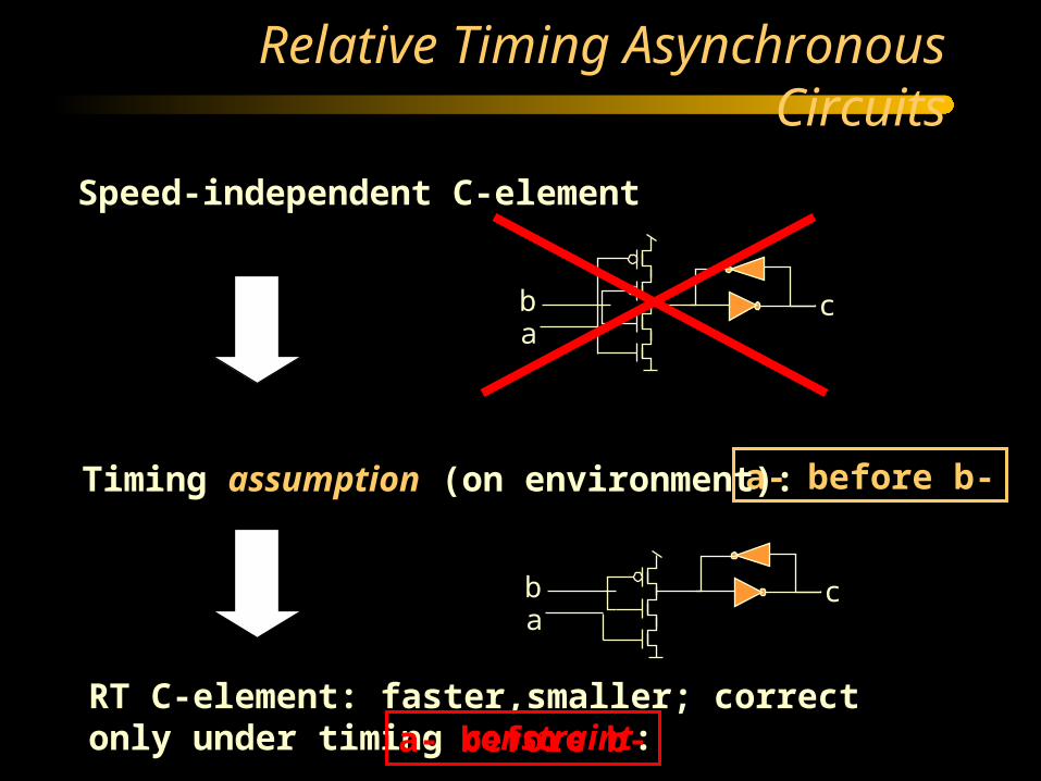
Speed-independent C-element
Relative Timing Asynchronous Circuits
a- before b-Timing assumption (on environment):
ab c
RT C-element: faster,smaller; correct only under timing constraint: a- before b-
ab c

Relative Timing Circuits
• Assumptions: “a before b” – for concurrent events: reduces reachable state space
– for ordered events: permits early enabling
– both increase don’t care space for logic synthesis => simplify logic (better area and timing)
• “Assume - if useful - guarantee” approach: assumptions are used by the tool to derive a circuit and required timing constraints that must be met in physical design flow
• Applied to design of the Rotating Asynchronous Pentium Processor(TM) Instruction Decoder (K.Stevens, S.Rotem et al. Intel Corporation)
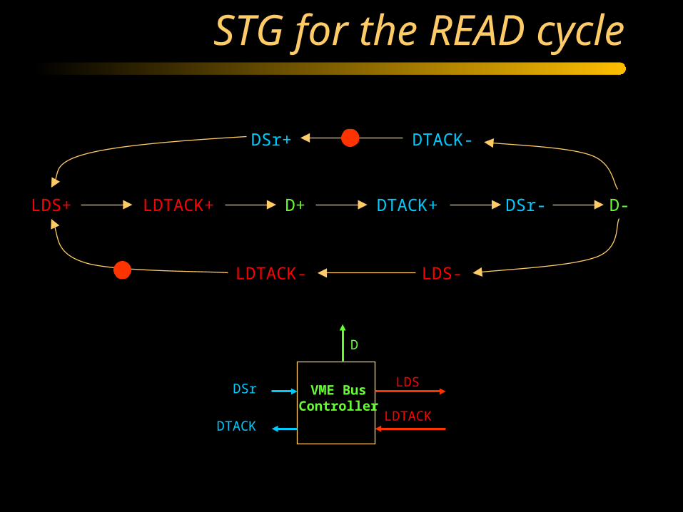
STG for the READ cycle
LDS+ LDTACK+ D+ DTACK+ DSr- D-
DTACK-
LDS-LDTACK-
DSr+
LDS
LDTACK
D
DSr
DTACK
VME BusController
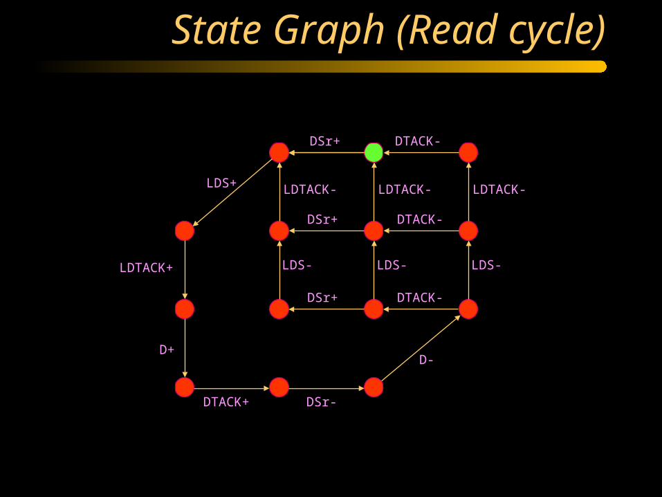
State Graph (Read cycle)
DSr+
DSr+
DSr+
DTACK-
DTACK-
DTACK-
LDS-LDS-LDS-
LDTACK- LDTACK- LDTACK-
D-
DSr-DTACK+
D+
LDTACK+
LDS+

Binary encoding of signals
DSr+
DSr+
DSr+
DTACK-
DTACK-
DTACK-
LDS-LDS-LDS-
LDTACK- LDTACK- LDTACK-
D-
DSr-DTACK+
D+
LDTACK+
LDS+
10000
10010
10110 01110
01100
0011010110
(DSr , DTACK , LDTACK , LDS , D)
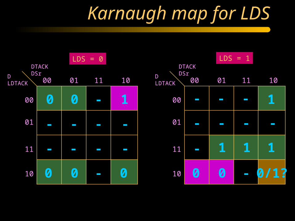
Karnaugh map for LDS
DTACKDSrD
LDTACK 00 01 11 10
00
01
11
10
DTACKDSrD
LDTACK 00 01 11 10
00
01
11
10
LDS = 0 LDS = 1
0 1-0
0 0 0 0 0 0/1?
1
111
-
-
-
---
- - - -
-
- ---
- - -

Speed-independent netlist
)(csccsc
csc
csc
LDTACKDSr
LDTACKD
DDTACK
DLDS
ER (LDS+)ER (LDS+)
ER (LDS-)ER (LDS-)
LDS-LDS-
LDS+
LDS-
1 0
0 1
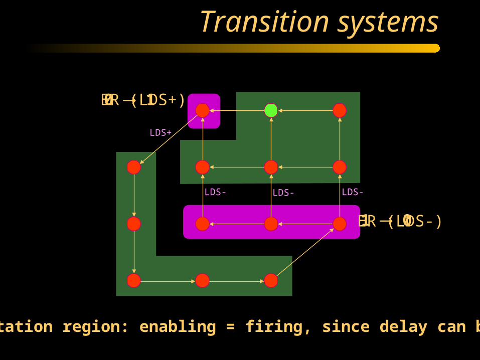
Transition systems
Excitation region: enabling = firing, since delay can be zero

Lazy Transition Systems
ER (LDS+)ER (LDS+)
ER (LDS-)ER (LDS-)
LDS-LDS-
LDS+
LDS-DTACK- FR (LDS-)FR (LDS-)
Event LDS- is lazy: firing = subset of enabling

Timing assumptions
• (a before b) for concurrent events: concurrency reduction for firing and enabling
• (a before b) for ordered events: early enabling
• (a simultaneous to b wrt c) for triples of events: combination of the above

Speed-independent Netlist
LDS+ LDTACK+ D+ DTACK+ DSr- D-
DTACK-
LDS-LDTACK-
DSr+
DTACKD
DSr
LDS
LDTACK
csc
map

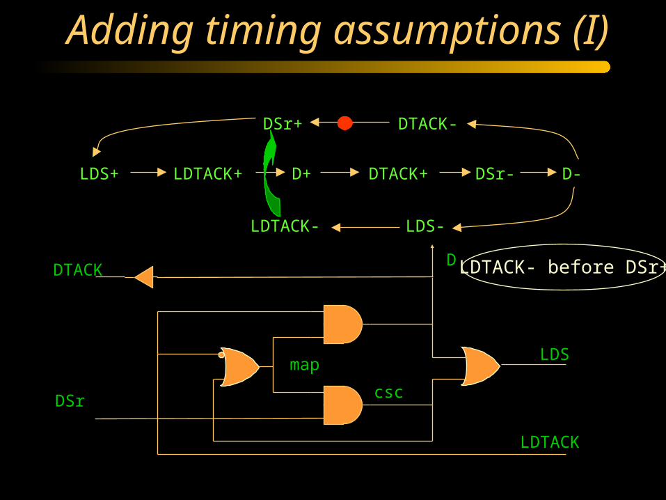
Adding timing assumptions (I)
LDS+ LDTACK+ D+ DTACK+ DSr- D-
DTACK-
LDS-LDTACK-
DSr+
DTACKD
DSr
LDS
LDTACK
csc
map
LDTACK- before DSr+
FAST
SLOW
Adding timing assumptions (I)
DTACKD
DSr
LDS
LDTACK
csc
map
LDS+ LDTACK+ D+ DTACK+ DSr- D-
DTACK-
LDS-LDTACK-
DSr+
LDTACK- before DSr+
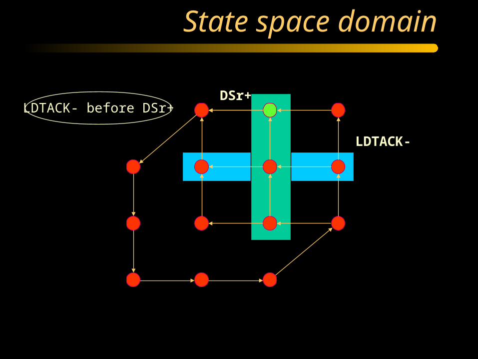
State space domain
LDTACK- before DSr+
LDTACK-
DSr+
State space domain
LDTACK- before DSr+
LDTACK-
DSr+

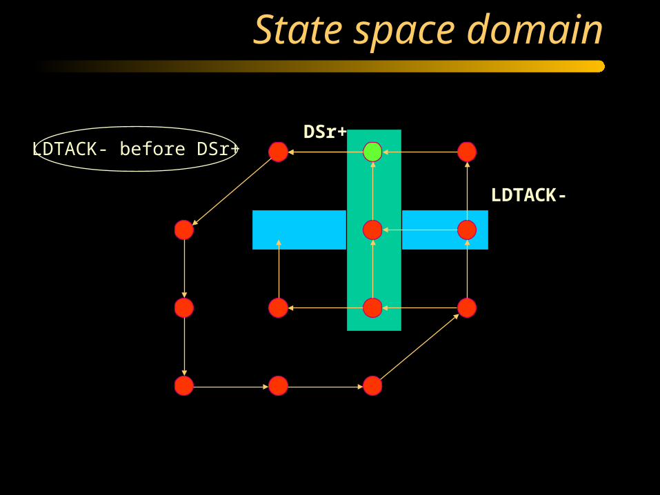
State space domain
LDTACK- before DSr+
LDTACK-
DSr+
Two more unreachable states

Boolean domain
DTACKDSrD
LDTACK 00 01 11 10
00
01
11
10
DTACKDSrD
LDTACK 00 01 11 10
00
01
11
10
LDS = 0 LDS = 1
0 1-0
0 0 0 0 0 0/1?
1
111
-
-
-
---
- - - -
-
- ---
- - -

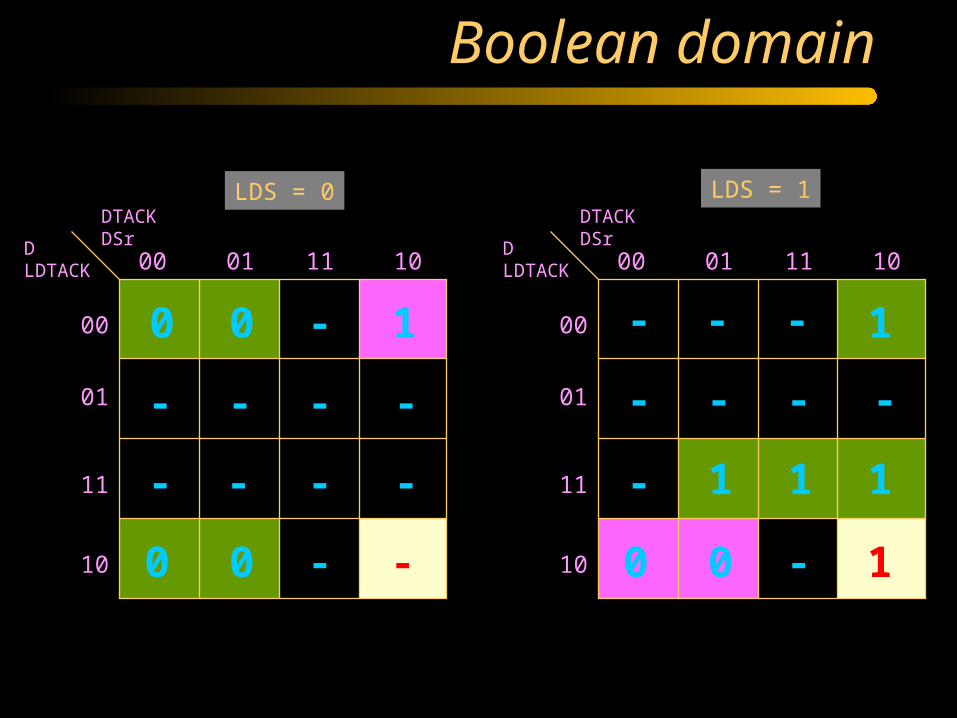
Boolean domain
DTACKDSrD
LDTACK 00 01 11 10
00
01
11
10
DTACKDSrD
LDTACK 00 01 11 10
00
01
11
10
LDS = 0 LDS = 1
0 1-0
0 0 - 0 0 1
1
111
-
-
-
---
- - - -
-
- ---
- - -
One more DC vector for all signals One state conflict is removed
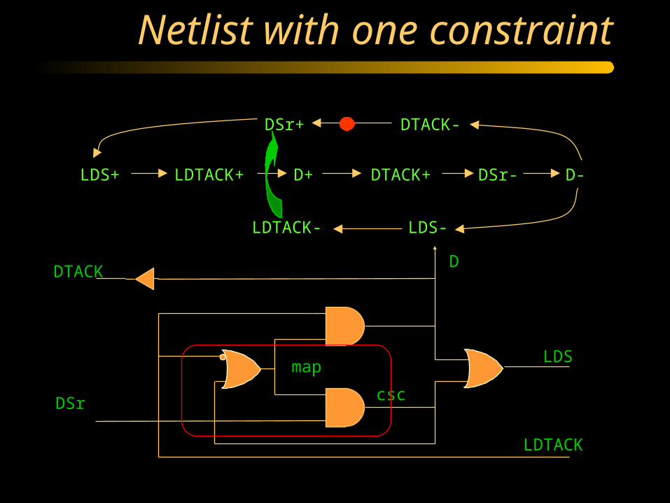
Netlist with one constraint
LDS+ LDTACK+ D+ DTACK+ DSr- D-
DTACK-
LDS-LDTACK-
DSr+
DTACKD
DSr
LDS
LDTACK
csc
map

Netlist with one constraint
LDS+ LDTACK+ D+ DTACK+ DSr- D-
DTACK-
LDS-LDTACK-
DSr+
DTACK D
DSr LDS
LDTACK
LDTACK- before DSr+
TIMING CONSTRAINT

Timing assumptions
• (a before b) for concurrent events: concurrency reduction for firing and enabling
• (a before b) for ordered events: early enabling
• (a simultaneous to b wrt c) for triples of events: combination of the above

Ordered events: early enabling
a
c
b
a
a
c
b
a
bb
c cF G
Logic for gate c may change

Adding timing assumptions (II)
LDS+ LDTACK+ D+ DTACK+ DSr- D-
DTACK-
LDS-LDTACK-
DSr+
DTACKD
DSr LDS
LDTACK
D- before LDS-

State space domain
LDS-
D-
Reachable space is unchanged
For LDS- enabling can be changed in one state
D- before LDS-
Potential enabling for LDS-
DSr-
Boolean domain
DTACKDSrD
LDTACK 00 01 11 10
00
01
11
10
DTACKDSrD
LDTACK 00 01 11 10
00
01
11
10
LDS = 0 LDS = 1
0 1-0
0 0 - 0 0 1
1
111
-
-
-
---
- - - -
-
- ---
- - -

Boolean domain
DTACKDSrD
LDTACK 00 01 11 10
00
01
11
10
DTACKDSrD
LDTACK 00 01 11 10
00
01
11
10
LDS = 0 LDS = 1
0 1-0
0 0 - 0 0 1
1
11-
-
-
-
---
- - - -
-
- ---
- - -
One more DC vector for one signal: LDSIf used: LDS = DSr, otherwise: LDS = DSr + D

Before early enabling
LDS+ LDTACK+ D+ DTACK+ DSr- D-
DTACK-
LDS-LDTACK-
DSr+
DTACKD
DSr LDS
LDTACK

Netlist with two constraints
LDS+ LDTACK+ D+ DTACK+ DSr- D-
DTACK-
LDS-LDTACK-
DSr+
LDTACK- before DSr+and D- before LDS-
TIMING CONSTRAINTSDTACKD
DSr LDS
LDTACK
Both timing assumptions are used for optimization and become constraints
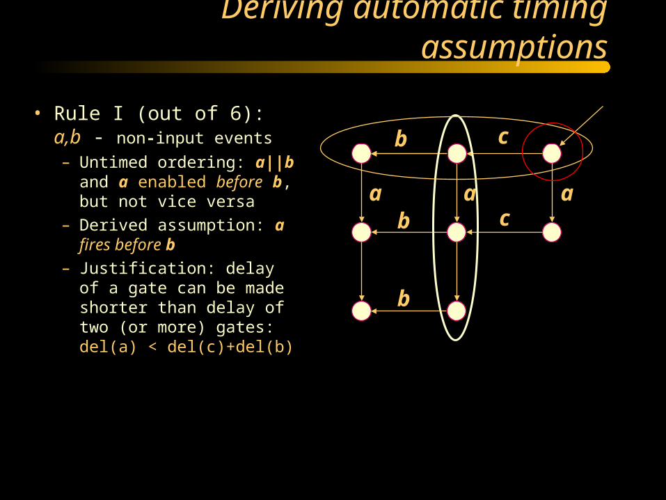
• Rule I (out of 6): a,b - non-input events
– Untimed ordering: a||b and a enabled before b, but not vice versa
– Derived assumption: a fires before b
– Justification: delay of a gate can be made shorter than delay of two (or more) gates: del(a) < del(c)+del(b)
Deriving automatic timing assumptions
aa a
b
b
b
c
c
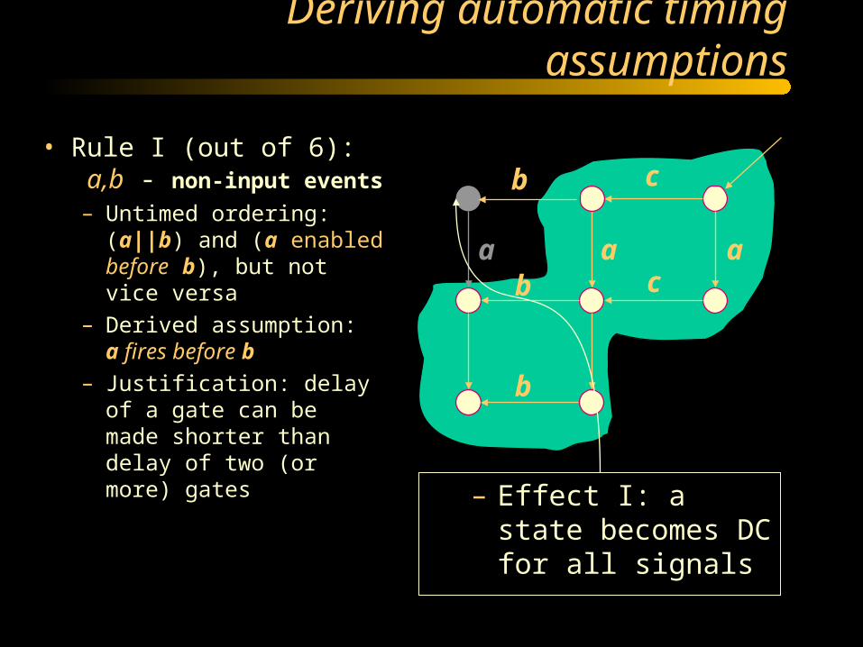
• Rule I (out of 6): a,b - non-input events
– Untimed ordering: (a||b) and (a enabled before b), but not vice versa
– Derived assumption: a fires before b
– Justification: delay of a gate can be made shorter than delay of two (or more) gates
Deriving automatic timing assumptions
aa a
b
b
b
c
c
– Effect I: a state becomes DC for all signals

• Rule I (out of 6): a,b - non-input events
– Untimed ordering: (a||b) and (a enabled before b), but not vice versa
– Derived assumption: a fires before b
– Justification: delay of a gate can be made shorter than delay of two (or more) gates
Deriving automatic timing assumptions
aa a
b
b
b
c
c
– Effect II: another state becomes local DC for signal of event b

Backannotation of Timing Constraints
• Timed circuits require post-verification
• Can synthesis tools help ?– Report the least stringent set of timing constraints
required for the correctness of the circuit
– Not all initial timing assumptions may be required
• Petrify reports a set of constraints for order of firing that guarantee the circuit correctness

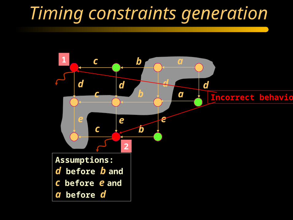
Timing constraints generation
abc
d
e
d d
e e
b
b
c
c
da
Assumptions:
d before b and
c before e and
a before d

Timing constraints generation
abc
d
e
Assumptions:
d before b and
c before e and
a before d
d d
e e
b
b
c
c
da

Timing constraints generation
abc
d
e
Assumptions:
d before b and
c before e and
a before d
d d
e e
b
b
c
cCorrect behavior
da
Timing constraints generation
abc
d
e
Assumptions:
d before b and
c before e and
a before d
d d
e e
b
b
c
c
1
2
Incorrect behavior
da

Covering incorrect behavior
abc
d
e
Assumptions:
d before b and
c before e and
a before d
d d
e e
b
b
c
c
1
2 4
3
{1, 3}
d before b
{1}
d before c
da
5
{2, 4}
c before e
Other possible constraints remove states from assumption domain => invalid

Covering incorrect behavior
abc
d
e
Assumptions:
d before b and
c before e and
a before d
d d
e e
b
b
c
c
1
2 4
3
{1}
d before c
da
5
{2, 4}
c before e
Constraints for the minimal cost solution:
d before c and
c before e
Timing aware state encoding
• Solve only state conflicts reachable in the RT assumptions domain
• Generate automatic timing assumptions for inserted state signals => state signals can be implemented as RT logic
• State variables inserted concurrently with I/O events => latency and cycle time reduction
Value of Relative Timing
• RT circuits provides up to 2-3x (1.3-2x) delay&area reduction with respect to SI circuits synthesized without (with) concurrency reduction
• Automatic generation of timing assumptions => foundation for automatic synthesis of RT circuits with area/performance comparable/better than manual
• Back-annotation of timing constraints => minimal required timing information for the back-end tools
• Timing-aware state encoding allows significant area/performance optimization
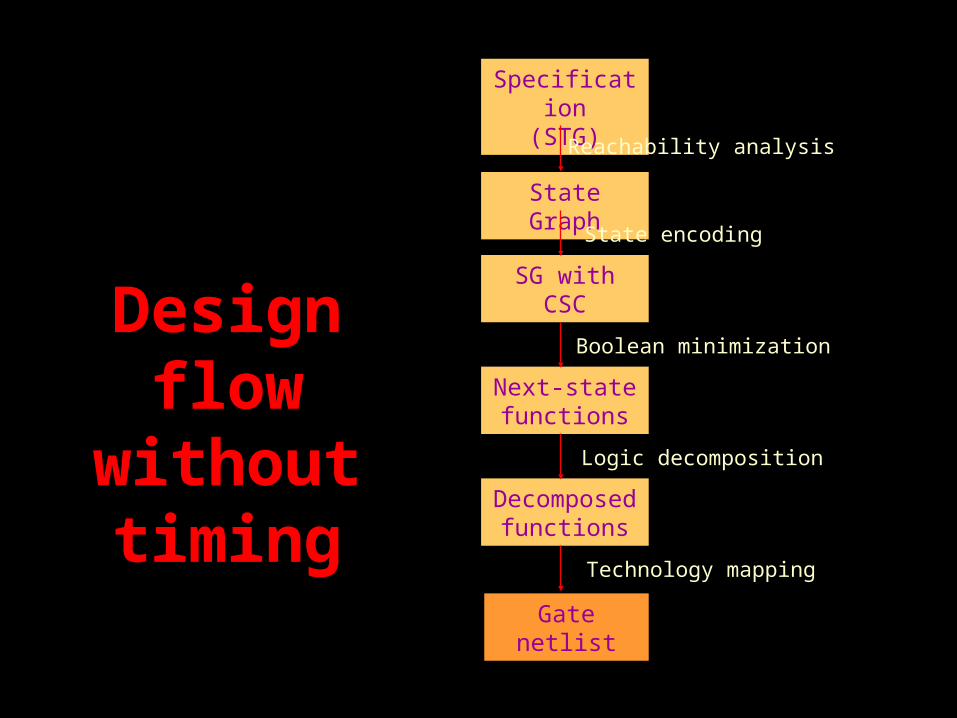
Specification(STG)
State Graph
SG withCSC
Next-state functions
Decomposed functions
Gate netlist
Reachability analysis
State encoding
Boolean minimization
Logic decomposition
Technology mapping
DesignDesignflowflow
withoutwithouttimingtiming

Specification(STG + user assumptions)
Lazy State Graph
Lazy SG withCSC
Next-state functions
Decomposed functions
Gate netlist
Reachability analysis
Timing-aware state encoding
Boolean minimization
Logic decomposition
Technology mapping
Design Flow with TimingDesign Flow with Timing
Required Timing Constraints
Automatic Timing Assumptions

FIFO example
FIFOli
lo
ro
ri
li-
li+
lo+
lo-
ro+
ro-
ri+
ri-

Speed-Independent Implementation
without concurrency reduction 3 state signals are required

SI implementation with concurrency reduction
li
lo ro
ri
xli-
li+
lo+
lo-
ro+
ro-
ri+
ri-
x+
x-
+gCgC +-
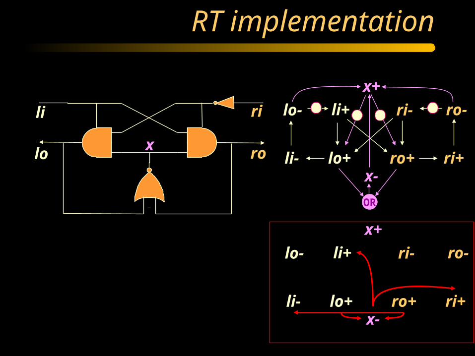
RT implementation
li
lo ro
ri
xli-
li+
lo+
lo-
ro+
ro-
ri+
ri-
x+
x-
OR
li-
li+
lo+
lo-
ro+
ro-
ri+
ri-
x+
x-

RT implementation
li
lo ro
ri
xli-
li+
lo+
lo-
ro+
ro-
ri+
ri-
x+
x-
OR
li-
li+
lo+
lo-
ro+
ro-
ri+
ri-
x+
x-
To satisfy the constraint: Delay(x- ) < Delay (ri+ ) andDelay(lo+) + Delay(x- ) < Delay(ro+ ) + Delay (ri+ ) All constraints are either satisfied by default oreasy to satisfy by sizing