Symposium Elektrisches Fliegen - 10.05.2016 Stuttgart … - Elektrisches... · Symposium...
26
The flyer of the Symposium already shows that distributed payload is one way to improve performance. The distribution of the payload along the wing span is interesting from a structural point of view but does not exploit the possibilities of electric power distribution. Therefore … 1 10.05.2016 Symposium Elektrisches Fliegen - Stuttgart 2016 - Martin Hepperle
-
Upload
nguyenngoc -
Category
Documents
-
view
219 -
download
0
Transcript of Symposium Elektrisches Fliegen - 10.05.2016 Stuttgart … - Elektrisches... · Symposium...

The flyer of the Symposium already shows that distributed payload is one way to improve performance.
The distribution of the payload along the wing span is interesting from a structural point of view but does not exploit the possibilities of electric power distribution. Therefore …
1
10.05.2016Symposium Elektrisches Fliegen -Stuttgart 2016 - Martin Hepperle

… we look at another option to distribute something over the wing span: the propulsion system.
This presentation shows some basic principles and some simple first order estimations to determine the order of magnitude of various effects. It does not present a optimized aircraft design – this may follow in a future presentation…
2
10.05.2016Symposium Elektrisches Fliegen -Stuttgart 2016 - Martin Hepperle

Before going into details we should keep in mind the world into which a propulsion system is born.Nobody wants to step back in terms of safety and costs or performance.Due to the high reliability of todays turbo-machinery, large aircraft usually have the minimum number of engines and can even fly on one engine over very long distances (e.g. ETOPS).
However, „electric propulsion“ or better „electric power distribution“ may enable to establish different system architectures which did not make too much sense in the past, when power was distributed by mechanical means.For example, the left hand / right hand side power distribution system of a tilt rotor aircraft comprises complex and heavy gearboxes and transmission shafts – but it is needed to provide adequate safety levels in case of engine failure.
3
10.05.2016Symposium Elektrisches Fliegen -Stuttgart 2016 - Martin Hepperle

What are the main effects we can expect from distributing the propulsion devices?1) we can increase the volume of air captured by the propulsion device (propeller) – this is
beneficial for efficiency.2) we can direct the stream of air being accelerated by the propellers over the wings to
increase the aerodynamic forces.3) we can interact with the boundary layer e.g. on a fuselage, where the low speed
boundary layer may pass through the propulsion system to be accelerated again.
4
10.05.2016Symposium Elektrisches Fliegen -Stuttgart 2016 - Martin Hepperle
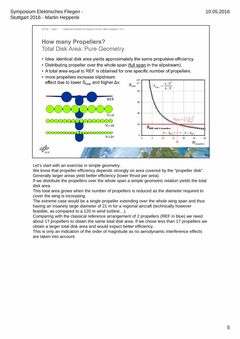
Let’s start with an exercise in simple geometry.We know that propeller efficiency depends strongly on area covered by the “propeller disk”. Generally larger areas yield better efficiency (lower thrust per area).If we distribute the propellers over the whole span a simple geometric relation yields the total disk area.This total area grows when the number of propellers is reduced as the diameter required to cover the wing is increasing.The extreme case would be a single propeller extending over the whole wing span and thus having an insanely large diameter of 21 m for a regional aircraft (technically however feasible, as compared to a 120 m wind turbine…).Comparing with the classical reference arrangement of 2 propellers (REF in blue) we need about 17 propellers to obtain the same total disk area. If we chose less than 17 propellers we obtain a larger total disk area and would expect better efficiency.This is only an indication of the order of magnitude as no aerodynamic interference effects are taken into account.
5
10.05.2016Symposium Elektrisches Fliegen -Stuttgart 2016 - Martin Hepperle

The effect of the total disk area is shown in this chart. As expected from the disk area graph we see that we can obtain the efficiency of the reference configuration when we use about 16 propellers covering the whole wing span.Using more propellers yields a smaller total disk area and reduces propulsive efficiency.
A Note on Reynolds-Number-Effects:Increasing the number of propellers and maintaining the tip Mach number for aerodynamic efficiency and noise levels also leads to a linear reduction of the Reynolds number on the propellers blades with the diameter. This can be partially avoided by adapting the number of blades (e.g. going from 5 blades of the reference aircraft down to 3 blades) to obtain wider blades. Additionally, these losses can be compensated by increasing the total disk area by reducing the number of propellers slightly (e.g. from 16 to 14).In-house studies at DLR have already shown that the Re-No-effect is present but not as large as it was feared.The effect is more pronounced on smaller vehicles (model aircraft type UAVs), where the Cfversus re curves are steeper.
6
10.05.2016Symposium Elektrisches Fliegen -Stuttgart 2016 - Martin Hepperle

Now disk area and efficiency are one thing but for the aircraft design the mass of the propellers is also of interest.Many smaller propellers are more lightweight than a few large propellers.The chart shows that we can expect approximately the same weight of the complete set of propellers if we use about 24 small propellers. If we use less than 24 propellers our propeller system would be more heavy than the reference system.It can be expected that by redesigning the propellers, e.g. with a reduced number of blades (from 5 to 3 or so) the mass of a 16 propeller system can be brought down to the mass of the system in the reference aircraft.
The weight of electric motors scales more directly with the power so that the total mass of the motors is not so strongly depending on the motor size. Here we can expect a smaller impact of the number of motors on total motor weight. Smaller higher RPM motors may even be more lightweight in power specific mass and preferable.These effects have to be taken into account when the aircraft is (re-)designed for distributed propulsion.
7
10.05.2016Symposium Elektrisches Fliegen -Stuttgart 2016 - Martin Hepperle

So far we have only thought about the propeller itself and the total number of propellers to obtain at least the same efficiency as in the reference case.As the propeller is not a disk but produces its thrust by rotating blades it creates a wake with axial acceleration and swirling motion behind the propeller.The energy contained in the swirling motion is lost for propulsion and one of the reasons that a propeller cannot have 100% efficiency (other losses are due to friction drag and due to the required axial acceleration).To get a feeling for the swirl the chart shows typical values for the swirl angles inside the wake and the link to efficiency as a function of RPM. We can see that driving a propeller with a given power at low RPM produces large swirl angles and large swirl losses. This due to the fact that the power is the product of torque and RPM and hence low RPM requires high torque and produces high swirl losses.In theory higher RPM would be preferred, but due to manufacturing and aerodynamic constraints larger propellers (with beneficial larger disk areas) would require extremely narrow blades at high RPM so that a compromise has to be made.In any case the accelerated, swirling flow “hits” the wing behind the propeller and we can expect some interaction effects.
8
10.05.2016Symposium Elektrisches Fliegen -Stuttgart 2016 - Martin Hepperle
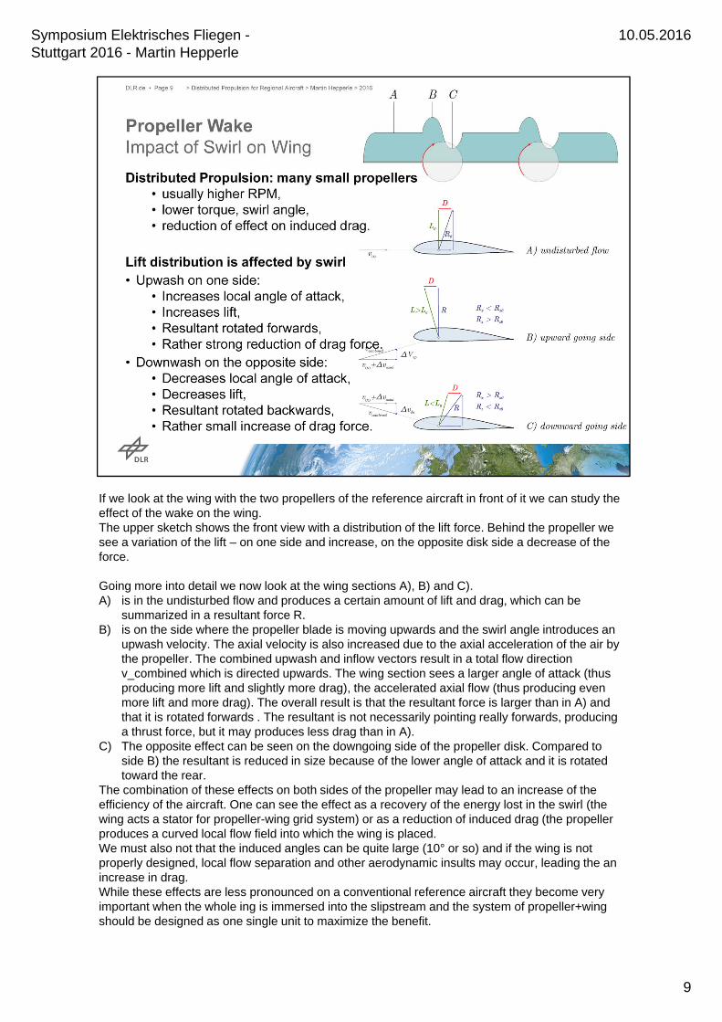
If we look at the wing with the two propellers of the reference aircraft in front of it we can study the effect of the wake on the wing.The upper sketch shows the front view with a distribution of the lift force. Behind the propeller we see a variation of the lift – on one side and increase, on the opposite disk side a decrease of the force.
Going more into detail we now look at the wing sections A), B) and C).A) is in the undisturbed flow and produces a certain amount of lift and drag, which can be
summarized in a resultant force R.B) is on the side where the propeller blade is moving upwards and the swirl angle introduces an
upwash velocity. The axial velocity is also increased due to the axial acceleration of the air by the propeller. The combined upwash and inflow vectors result in a total flow direction v_combined which is directed upwards. The wing section sees a larger angle of attack (thus producing more lift and slightly more drag), the accelerated axial flow (thus producing even more lift and more drag). The overall result is that the resultant force is larger than in A) and that it is rotated forwards . The resultant is not necessarily pointing really forwards, producing a thrust force, but it may produces less drag than in A).
C) The opposite effect can be seen on the downgoing side of the propeller disk. Compared to side B) the resultant is reduced in size because of the lower angle of attack and it is rotated toward the rear.
The combination of these effects on both sides of the propeller may lead to an increase of the efficiency of the aircraft. One can see the effect as a recovery of the energy lost in the swirl (the wing acts a stator for propeller-wing grid system) or as a reduction of induced drag (the propeller produces a curved local flow field into which the wing is placed.We must also not that the induced angles can be quite large (10° or so) and if the wing is not properly designed, local flow separation and other aerodynamic insults may occur, leading the an increase in drag.While these effects are less pronounced on a conventional reference aircraft they become very important when the whole ing is immersed into the slipstream and the system of propeller+wingshould be designed as one single unit to maximize the benefit.
9
10.05.2016Symposium Elektrisches Fliegen -Stuttgart 2016 - Martin Hepperle

Distributing the propulsion devices evenly over the wing span is simple but probably not the best arrangement.The local lift forces and the strength of the trailing vortices vary along the span and it is not clear what the best distribution of power and propeller size is. Patents exit that show other options to place the engines (maybe a bit difficult from a structural and mass point of view).The interaction of the wakes of propeller and wing is complicated by the fact the propeller wake is split by the wing into an upper and a lower half which the induce a spanwise flow vector into the wake. Besides bending the two “half-wakes” (upper and lower) into opposite directions (inboard resp. outboard) this produces an additional vortical shear layer which interacts with the shear layer of the wing.These physical effects are all understood in principle, but how to exploit them in the most beneficial manner for aircraft design is not yet fully clear.Again: one should carefully design the propeller system together with the wing in wing aerodynamics, propelelr aerodynamics and structures (weight).
10
10.05.2016Symposium Elektrisches Fliegen -Stuttgart 2016 - Martin Hepperle

On top of these effects which are related to distribution the propulsion system over the wing span there are two additional things to consider.One „overshadowing“ global effect is important for all propulsion systems but sometimes overlooked or forgotten when fancy new configurations are drawn up.
The second one is the possibility to interact with the boundary layer. when the dimensions of propulsion system and boundary layer approach each other.
11
10.05.2016Symposium Elektrisches Fliegen -Stuttgart 2016 - Martin Hepperle
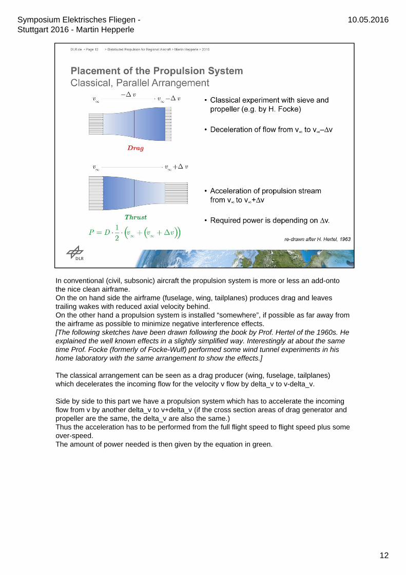
In conventional (civil, subsonic) aircraft the propulsion system is more or less an add-onto the nice clean airframe.On the on hand side the airframe (fuselage, wing, tailplanes) produces drag and leaves trailing wakes with reduced axial velocity behind.On the other hand a propulsion system is installed “somewhere”, if possible as far away from the airframe as possible to minimize negative interference effects.[The following sketches have been drawn following the book by Prof. Hertel of the 1960s. He explained the well known effects in a slightly simplified way. Interestingly at about the same time Prof. Focke (formerly of Focke-Wulf) performed some wind tunnel experiments in his home laboratory with the same arrangement to show the effects.]
The classical arrangement can be seen as a drag producer (wing, fuselage, tailplanes) which decelerates the incoming flow for the velocity v flow by delta_v to v-delta_v.
Side by side to this part we have a propulsion system which has to accelerate the incoming flow from v by another delta_v to v+delta_v (if the cross section areas of drag generator and propeller are the same, the delta_v are also the same.)Thus the acceleration has to be performed from the full flight speed to flight speed plus some over-speed.The amount of power needed is then given by the equation in green.
12
10.05.2016Symposium Elektrisches Fliegen -Stuttgart 2016 - Martin Hepperle
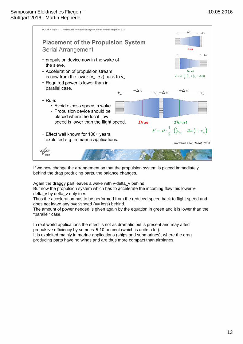
If we now change the arrangement so that the propulsion system is placed immediately behind the drag producing parts, the balance changes.
Again the draggy part leaves a wake with v-delta_v behind.But now the propulsion system which has to accelerate the incoming flow this lower v-delta_v by delta_v only to v.Thus the acceleration has to be performed from the reduced speed back to flight speed and does not leave any over-speed (== loss) behind.The amount of power needed is given again by the equation in green and it is lower than the “parallel” case.
In real world applications the effect is not as dramatic but is present and may affect propulsive efficiency by some +/-5-10 percent (which is quite a lot). It is exploited mainly in marine applications (ships and submarines), where the drag producing parts have no wings and are thus more compact than airplanes.
13
10.05.2016Symposium Elektrisches Fliegen -Stuttgart 2016 - Martin Hepperle
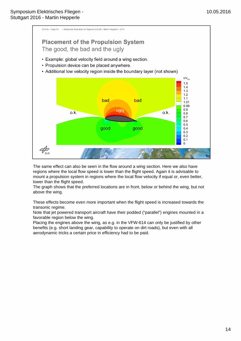
The same effect can also be seen in the flow around a wing section. Here we also have regions where the local flow speed is lower than the flight speed. Again it is advisable to mount a propulsion system in regions where the local flow velocity if equal or, even better, lower than the flight speed.The graph shows that the preferred locations are in front, below or behind the wing, but not above the wing.
These effects become even more important when the flight speed is increased towards the transonic regime.Note that jet powered transport aircraft have their podded (“parallel”) engines mounted in a favorable region below the wing.Placing the engines above the wing, as e.g. in the VFW-614 can only be justified by other benefits (e.g. short landing gear, capability to operate on dirt roads), but even with all aerodynamic tricks a certain price in efficiency had to be paid.
14
10.05.2016Symposium Elektrisches Fliegen -Stuttgart 2016 - Martin Hepperle
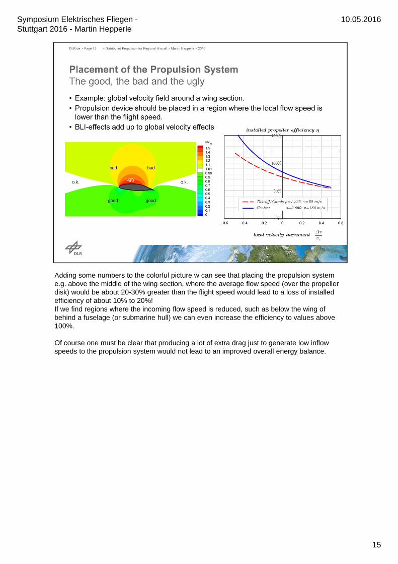
Adding some numbers to the colorful picture w can see that placing the propulsion system e.g. above the middle of the wing section, where the average flow speed (over the propeller disk) would be about 20-30% greater than the flight speed would lead to a loss of installed efficiency of about 10% to 20%!If we find regions where the incoming flow speed is reduced, such as below the wing of behind a fuselage (or submarine hull) we can even increase the efficiency to values above 100%.
Of course one must be clear that producing a lot of extra drag just to generate low inflow speeds to the propulsion system would not lead to an improved overall energy balance.
15
10.05.2016Symposium Elektrisches Fliegen -Stuttgart 2016 - Martin Hepperle
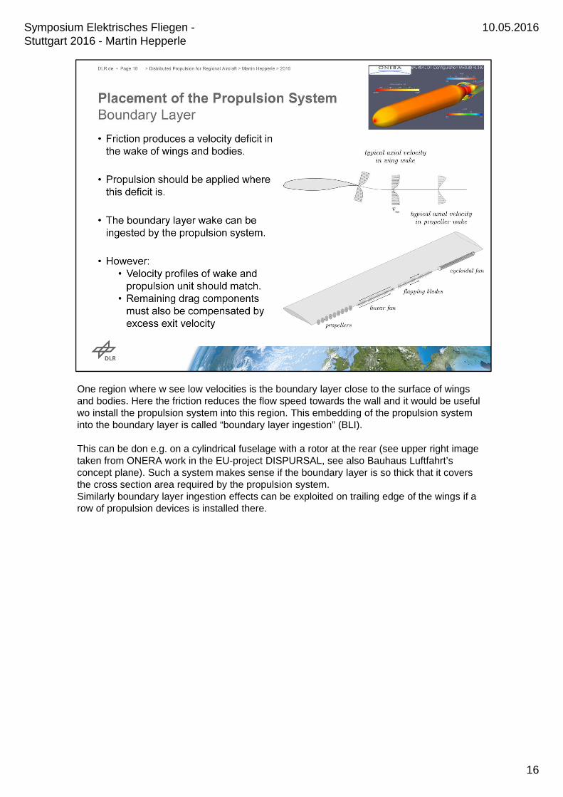
One region where w see low velocities is the boundary layer close to the surface of wings and bodies. Here the friction reduces the flow speed towards the wall and it would be useful wo install the propulsion system into this region. This embedding of the propulsion system into the boundary layer is called “boundary layer ingestion” (BLI).
This can be don e.g. on a cylindrical fuselage with a rotor at the rear (see upper right image taken from ONERA work in the EU-project DISPURSAL, see also Bauhaus Luftfahrt’sconcept plane). Such a system makes sense if the boundary layer is so thick that it covers the cross section area required by the propulsion system.Similarly boundary layer ingestion effects can be exploited on trailing edge of the wings if a row of propulsion devices is installed there.
16
10.05.2016Symposium Elektrisches Fliegen -Stuttgart 2016 - Martin Hepperle

In order to assess whether the BLI concept makes sense for a regional aircraft we can make a simple comparison of the cross sections of the air captured by the propulsion system.The reference aircraft with its two large propellers (3.6 m diameter each) captures already a quite large cross section (about 20m²) of air to obtain a rather good propeller efficiency.On the other hand the boundary layers on this relatively small aircraft are not very thick. On fuselage and wing the thicknesses are between 5 and 50 mm, depending on flight condition. These areas could benefit from BLI but they amount only to less than 1 m².Thus it can be said without further detailed analysis that BLI effects will be very small or negligible on this type of aircraft because it has already quite efficient (large) propulsion devices.
For faster and larger jet-powered aircraft the picture is a bit different as they have smaller (less efficient) engine diameters and thus lower capture areas and the boundary layers can be thicker due to the larger dimensions. Thus a certain benefit (in the order of 5% energy consumption) can be found for larger aircraft. This benefit will shrink in the future, when engines are replaced by larger engines (UHBR or even propellers).
17
10.05.2016Symposium Elektrisches Fliegen -Stuttgart 2016 - Martin Hepperle
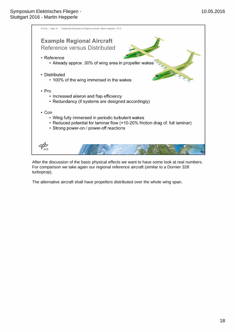
After the discussion of the basic physical effects we want to have some look at real numbers.For comparison we take again our regional reference aircraft (similar to a Dornier 328 turboprop).
The alternative aircraft shall have propellers distributed over the whole wing span.
18
10.05.2016Symposium Elektrisches Fliegen -Stuttgart 2016 - Martin Hepperle
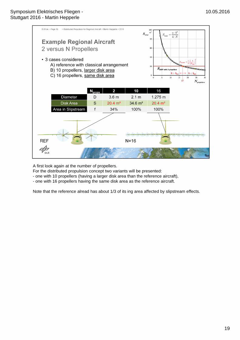
A first look again at the number of propellers.For the distributed propulsion concept two variants will be presented:- one with 10 propellers (having a larger disk area than the reference aircraft),- one with 16 propellers having the same disk area as the reference aircraft.
Note that the reference alread has about 1/3 of its ing area affected by slipstream effects.
19
10.05.2016Symposium Elektrisches Fliegen -Stuttgart 2016 - Martin Hepperle
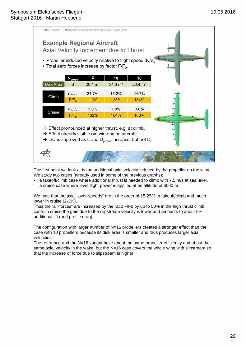
The first point we look at is the additional axial velocity induced by the propeller on the wing.We study two cases (already used in some of the previous graphs): - a takeoff/climb case where additional thrust is needed to climb with 7.5 m/s at sea level,- a cruise case where level flight power is applied at an altitude of 6000 m.
We note that the axial „over-speeds“ are in the order of 15-25% in takeoff/climb and much lower in cruise (2-3%).Thus the “air-forces” are increased by the ratio F/F0 by up to 50% in the high thrust climb case. In cruise the gain due to the slipstream velocity is lower and amounts to about 6% additional lift (and profile drag).
The configuration with larger number of N=16 propellers creates a stronger effect than the case with 10 propellers because its disk area is smaller and thus produces larger axial velocities. The reference and the N=16 variant have about the same propeller efficiency and about the same axial velocity in the wake, but the N=16 case covers the whole wing with slipstream so that the increase of force due to slipstream is higher.
20
10.05.2016Symposium Elektrisches Fliegen -Stuttgart 2016 - Martin Hepperle
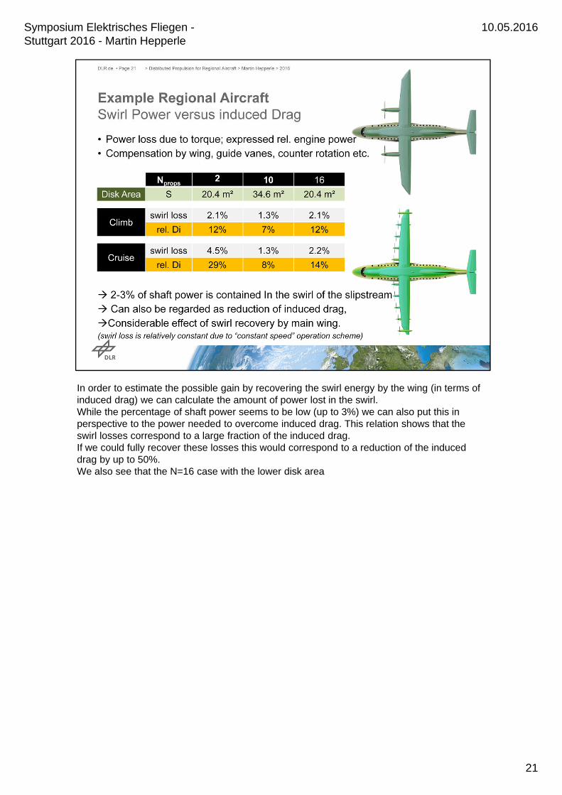
In order to estimate the possible gain by recovering the swirl energy by the wing (in terms of induced drag) we can calculate the amount of power lost in the swirl.While the percentage of shaft power seems to be low (up to 3%) we can also put this in perspective to the power needed to overcome induced drag. This relation shows that the swirl losses correspond to a large fraction of the induced drag. If we could fully recover these losses this would correspond to a reduction of the induced drag by up to 50%.We also see that the N=16 case with the lower disk area
21
10.05.2016Symposium Elektrisches Fliegen -Stuttgart 2016 - Martin Hepperle
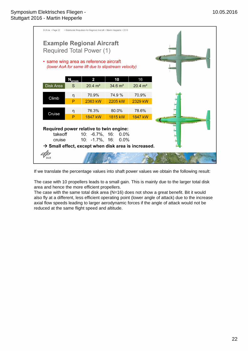
If we translate the percentage values into shaft power values we obtain the following result:
The case with 10 propellers leads to a small gain. This is mainly due to the larger total disk area and hence the more efficient propellers.The case with the same total disk area (N=16) does not show a great benefit. Bit it would also fly at a different, less efficient operating point (lower angle of attack) due to the increase axial flow speeds leading to larger aerodynamic forces if the angle of attack would not be reduced at the same flight speed and altitude.
22
10.05.2016Symposium Elektrisches Fliegen -Stuttgart 2016 - Martin Hepperle

Therefore we also look at a case where the wing area has been reduce to obtain a similar same angle of attack of the wing in climb. Based on the average increase of the aerodynamic forces due to the slip stream the wing chord has been reduced by 20%.Now the picture looks more promising:All distributed propulsion variants show a reduction of the required shaft power which varies between 10 and 20%.Of course further optimization and more detailed design and adaptation of the flight mission is required to sharpen these estimates.The smaller wing leads also to a higher wing loading (beneficial for passenger comfort at the relatively low cruise altitudes of propeller driven regional aircraft) but possibly also to ahigher wing mass (thinner wing, partially compensated by distributed mass of propulsion system). The cruising altitude and cruise lift coefficient would also have to be adapted to the wing loading and new aspect ratio.
The conclusions of this study are that a new wing layout is required to make use of the advantages of a distributed propulsion system.This new wing must be designed together with the propellers and their wakes.
23
10.05.2016Symposium Elektrisches Fliegen -Stuttgart 2016 - Martin Hepperle
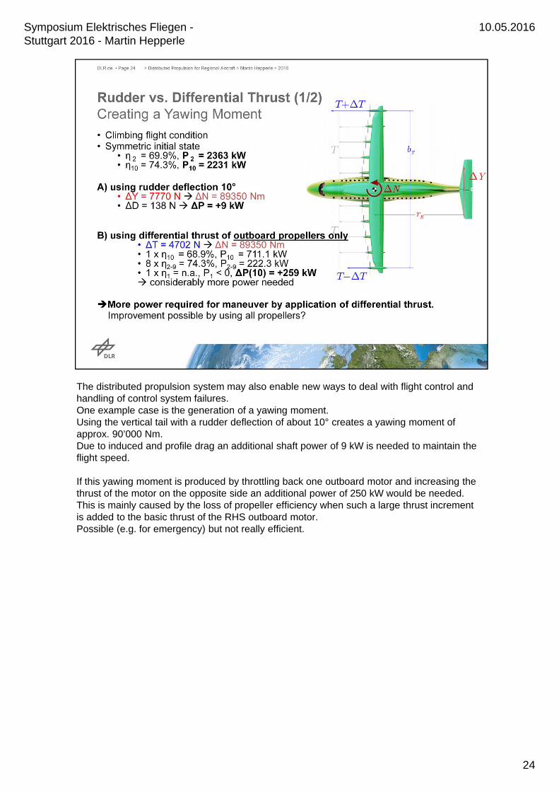
The distributed propulsion system may also enable new ways to deal with flight control and handling of control system failures.One example case is the generation of a yawing moment.Using the vertical tail with a rudder deflection of about 10° creates a yawing moment of approx. 90’000 Nm.Due to induced and profile drag an additional shaft power of 9 kW is needed to maintain the flight speed.
If this yawing moment is produced by throttling back one outboard motor and increasing the thrust of the motor on the opposite side an additional power of 250 kW would be needed. This is mainly caused by the loss of propeller efficiency when such a large thrust increment is added to the basic thrust of the RHS outboard motor.Possible (e.g. for emergency) but not really efficient.
24
10.05.2016Symposium Elektrisches Fliegen -Stuttgart 2016 - Martin Hepperle
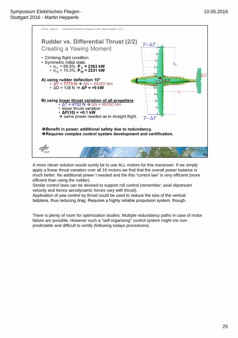
A more clever solution would surely be to use ALL motors for this maneuver. If we simply apply a linear thrust variation over all 16 motors we find that the overall power balance is much better. No additional power I needed and the this “control law” is very efficient (more efficient than using the rudder).Similar control laws can be devised to support roll control (remember: axial slipstream velocity and hence aerodynamic forces vary with thrust).Application of yaw control by thrust could be used to reduce the size of the vertical tailplane, thus reducing drag. Requires a highly reliable propulsion system, though.
There is plenty of room for optimization studies. Multiple redundancy paths in case of motor failure are possible. However such a “self-organizing” control system might me non-predictable and difficult to certify (following todays procedures).
25
10.05.2016Symposium Elektrisches Fliegen -Stuttgart 2016 - Martin Hepperle

Distributing the propulsion units over the airframe (here: wing span) can produce strong interaction effects.The well known physical phenomena have often lead to detrimental effects, so that we seen interference as a negative effects to avoid.But there are also ways to exploit such effects to obtain a better overall system. This requires more design work on the combined, tightly coupled system of propulsion devices and airframe.Using basic principles it is possible to estimate the order of magnitude of various effects and to focus on the most promising.
Performance predictions are difficult and require carful bookkeeping of energy flows and aerodynamic interactions. Here high fidelity tools must be used to optimize geometries and overall arrangement. Results can then be fed back into simpler and faster preliminary design tools to size and improve the overall aircraft design. Experience has shown that experiments with respect to the accurate determination of overall efficiency are extremely difficult.
Many new options become obvious in the areas of stability and control – some are interesting and useful, some all undesired.Optimization of “pre-canned” control laws as well as self-adapting systems come to mind. Small-scale experiments using clever flight control systems could be helpful to demonstratethe additional degrees of freedom and can be very motivating e.g. for students.
More ideas related to certification must be developed. Current rules should not be seen as rigid borders but the safety aspects behind these rules must be considered.
26
10.05.2016Symposium Elektrisches Fliegen -Stuttgart 2016 - Martin Hepperle