
SW CONFIGURATION OF THE CIB NETWORK - … · OBSAH 3 TXV 003 46.01 . SW configuration of the CIB...
51
. PROGRAMOVATELNÉ AUTOMATY SW CONFIGURATION OF THE CIB NETWORK TXV 003 46.01
Transcript of SW CONFIGURATION OF THE CIB NETWORK - … · OBSAH 3 TXV 003 46.01 . SW configuration of the CIB...

.
PROGRAMOVATELNÉ AUTOMATY
SW CONFIGURATION OF THE CIB NETWORK
TXV 003 46.01


OBSAH
3 TXV 003 46.01 .
SW configuration of the CIB network
1. edition – July 2008
CONTENT
1. INTRODUCTION.......................................................Chyba! Záložka není definována.
2. INELS MASTER DECLARATION........................... ....................................................4 2.1. Configuration ................................................... Chyba! Záložka není definována. 2.2. Transferred data structure ............................... Chyba! Záložka není definována. 2.3. Conversion tables............................................ Chyba! Záložka není definována.
3. INELS UNITS DECLARATION ........................ ........................................................12 3.1. 3101 - DA2-22M ..................................................................................................13 3.2. 3102 - DAC2-04B ................................................................................................15 3.3. 3104 - DAC2-04M................................................................................................16 3.4. 3107 - IART2-1....................................................................................................17 3.5. 3108 – IDRT2-1...................................................................................................18 3.6. 3109 - IM2-140M .................................................................................................19 3.7. 3110 - IM2-80B....................................................................................................20 3.8. 3111 - KEY2-01R ................................................................................................21 3.9. 3112 - KEY2-01...................................................................................................22 3.10. 3113 – LM2-11B ..............................................................................................23 3.11. 3114 – LBC2-02M............................................................................................24 3.12. 3115 - SA2-01B/Ni ...........................................................................................25 3.13. 3116 - SA2-01B/Sn ..........................................................................................26 3.14. 3117 - SA2-02B/Ni ...........................................................................................27 3.15. 3118 - SA2-02B/Sn ..........................................................................................28 3.16. 3119 - SA2-02M/Ni ..........................................................................................29 3.17. 3120 - SA2-02M/Sn .........................................................................................30 3.18. 3121 - SA2-04M/Ni ..........................................................................................31 3.19. 3122 - SA2-04M/Sn .........................................................................................32 3.20. 3123 - SOPHY2 ...............................................................................................33 3.21. 3124 – SOPHY2-L ...........................................................................................35 3.22. 3125 - WSB2-20 ..............................................................................................37 3.23. 3126 - WSB2-40 ..............................................................................................38 3.24. 3127 - WSB2-80 ..............................................................................................39 3.25. 3128 – MI2-02M...............................................................................................40 3.26. 3129 – FCC2-01 ..............................................................................................41 3.27. 3133 – WMR2-11.............................................................................................42 3.28. 3143 – WSB2-60..............................................................................................43 3.29. 3148– ADC2-40M ............................................................................................44 3.30. 3149 – IM2-20B ...............................................................................................46 3.31. 3150- IM2-40B .................................................................................................47 3.32. 3691- DIM6 ......................................................................................................48

SW KONFIGURACE CIB SÍTĚ
TXV 003 46.01 4
1. INTRODUCTION
The aim of the handbook is to introduce the SW configuration INELS of the CIB network in the Mosaic programmable environment to the PLC Tecomat Foxtrot user. It provides information on INELS master configuration, configuration of individual INELS units and transferred data structures of particular INELS units.
The configuration itself is undertaken on the basis of the Mosaic dialogs. Declarations mentioned in this handbook are, therefore, generated automatically by the Mosaic and should serve to the user as a model in case of „manual“ comfiguration of the INELS network and to understand the significance of transferred data structures of INELS units.
2. INELS MASTER DECLARATION
2.1. Configuration
The INELS master addition to the PLC Tecomat Foxtrot configuration is undertaken via the dialog HW configuration in the Project manager. CPU Tecomat Foxtrot allows the servicing of one CIB line via the internal INELS master MI2-01M and up to 8 external CIB lines via 4 external INELS masters MI2-02M (external master MI2-02M contains 2 CIB lines).
The control initization of the internal INELS master MI2-01M is done on the Central module panel.
Fig. 2.1 The control initization of the internal INELS master
Control addition and initization of external INELS masters MI2-02M is done on External
CIB dialog panel.

2. INELS MASTER DECLARATION
5 TXV 003 46.01 .
Fig. 2.2 Control addition and initization of external INELS master
SW INELS master configuration for control of INELS items to the CIB bus is done via
the dialog Items/devices manager. The dialog is accesible via the window HW configuration after clicking on icon on the INELS master line.
Fig. 2.3 SW configuration of INELS master

SW KONFIGURACE CIB SÍTĚ
TXV 003 46.01 6
Particular INELS units can be added to the list manually using the button Add unit , or automatically according to the CPU connected via the button Load configuration from the CPU. When choosing units manually, it is necessary to set the address to the field HW unit address. This address is set to the unit during the production and is marked on each unit. The address is a 4-numbered code in hexadecimal (sixteenth) format. It is not possible to operate more units with the similar HW address on one CIB line!!!
Using items Naming/alias the symbolic name can be set under which the structure of inputs/outputs of the set unit will be accesible.
Based on this dialog, the initialisation table of INELS master is generated. The part of
the initialisation table is a hyperlink to transferred data zone location (input and output), hyperlink to diagnostics zone (status and errors) and a list of operated INELS units.
The initialisation table of the INELS master is described using the bellow stated
structures:
#struct _TTS_INEHead ;The header of the initialisat ion table of the chanel in the INE mode word code, ;00 code 00C9 for data validity contr ol word mode_, ;02 data exchange modes = 0x0000 _TTS_SetSCH parSCH, ;04 basic parameters _TTS_Modem modem, ;0C modem parameters – not use d long iin, ;18 input data address long iout, ;1C output data address long istat, ;20 status data address long ierr, ;24 error data address word tabConvIN, ;28 conversion table of input da ta zone number word tabConvOUT,;2A conversion table of output d ata zone number byte nnt, ;2C real number of controlled uni ts byte nline ;2D number of following lines in unit description #struct _TTS_LINE ;Initialisation table line wi th the unit information byte mkom, ;00 communcation mode ; .7 = 0/1 – unit non-control led/controlled ; .6 = 1 – unit is part of th e master(internal periphery.) byte rez, ; not used (rezerve) word tabini, ;02 unit initialisation data table n umber word lein, ;04 input data lenght of the unit (bytes) word leout ;06 output data lenght of the unit (b ytes)
The initialisation table of INELS master itself (INE channel) is described by this structure:
#struct _TTS_INEINIT_CH ; The structure of INE chan nel initialisation table _TTS_INEHead Head, ;table header _TTS_LINE[33] Line ;INELS units initialisation lines

2. INELS MASTER DECLARATION
7 TXV 003 46.01 .
Example of the declaration of the INE channel initialisation table where the sample of INELS units is represented:
; ; INELS channel initialisation table (CIB lines) ; #table _TTS_INEINIT_CH _Table_INELS_MI_CIB = $00C9,$0000, ;code, mode (set)
9,63,$0C,0,0,0,0,0, ;basic parameters (set) 0,0,0,0, ;modem parameters(set) __offset32(MI_CIB_IN), ;iin – input data __offset32(MI_CIB_OUT), ;iout – output data
__offset32(INE_STAT_MI_CIB),;istat – status zon e __offset32(INE_ERR_MI_CIB), ;ierr –communication
erros __indx (Konvert_IN_MI_CIB), ;input conversion table __indx (Konvert_OUT_MI_CIB),;output conversion
table 31+1, ;real unit number 32+1, ;description lines number $C0,$00, __indx (INI_MI2_02) , 2,0,;3128,internal $80,$00, __indx (INI_DA2_22 M), 4,2, ;3101
$80,$00, __indx (INI_DAC2_04B), 2,4, ;3102 $80,$00, __indx (INI_DAC2_04M), 0,4, ;3104 $80,$00, __indx (INI_IART2_1), 5,1, ;3107 $80,$00, __indx (INI_IDRT2_1), 5,1, ;3108 $80,$00, __indx (INI_IM2_140M), 3,0, ;3109 $80,$00, __indx (INI_IM2_80B), 4,0, ;3110 $80,$00, __indx (INI_KEY2_01R_BL),6,16,;3111 $80,$00, __indx (INI_KEY2_01_BL), 1,16,;3112 $80,$00, __indx (INI_LM2_11B), 3,1, ;3113 $80,$00, __indx (INI_LBC2_02M), 1,2, ;3114 $80,$00, __indx (INI_SA2_01B_Ni), 2,1, ;3115 $80,$00, __indx (INI_SA2_01B_Sn), 2,1, ;3116 $80,$00, __indx (INI_SA2_02B_Ni), 2,1, ;3117 $80,$00, __indx (INI_SA2_02B_Sn), 2,1, ;3118 $80,$00, __indx (INI_SA2_02M_Ni), 1,1, ;3119 $80,$00, __indx (INI_SA2_02M_Sn), 1,1, ;3120 $80,$00, __indx (INI_SA2_04M_Ni), 1,1, ;3121 $80,$00, __indx (INI_SA2_04M_Sn), 1,1, ;3122 $80,$00, __indx (INI_SOPHY2), 9,6, ;3123 $80,$00, __indx (INI_SOPHY2_L), 7,4, ;3124 $80,$00, __indx (INI_WSB2_20), 3,1, ;3125 $80,$00, __indx (INI_WSB2_40), 3,1, ;3126 $80,$00, __indx (INI_WSB2_80), 3,1, ;3127 $80,$00, __indx (INI_FCC2_01), 4,2, ;3129 $80,$00, __indx (INI_WMR2_11), 8,1, ;3133 $80,$00, __indx (INI_ADC2_40M), 9,0, ;3135 $80,$00, __indx (INI_WSB2_60), 3,2, ;3143 $80,$00, __indx (INI_ADC2_40M), 9,0, ;3148 $80,$00, __indx (INI_IM2_20B), 4,0, ;3149 $80,$00, __indx (INI_IM2_40B), 4,0, ;3150 $80,$00, __indx (INI_DIM6), 3,1 ;3691

SW KONFIGURACE CIB SÍTĚ
TXV 003 46.01 8
Example of the declaration of the INE channel (internal INELS master):
#struct TmodulE1 ;module declaration structure USINT version, ;description version USINT rack, ;rack address USINT address, ;module address on the rack UINT LogAddress, ;logic address UINT LenInputs, ;input data zone lenght UINT LenOutputs, ;output data zone lenght DINT OffsetInputs, ; input data zone posi tion DINT OffsetOutputs, ; output data zone pos ition UINT InitTable ;initialisation table inde x #module TmodulE1 1, 0, 2, $0110, 10, 2, __offset( Statistic_CH_INELS), __offset(Control_CH_INELS), __indx (_Table_INELS_MI _CIB)
INELS master within the CPU Foxtrot (internal master) contains one INE channel and is always mapped into the rack 0 (variable rack=0) onto the address 2 (variable address=2 ).
INELS master connected to the CPU Foxtrot via the external TCL2 bus (external master) contains two INE channels and those are always mapped into the frame 3 (variable rack=3), address is optionable via the address switcher within the range 0 to 15 (variable address=0 to 15).
The signification of particular items of the initialisation table:
code - channel type identification code, set to $00C9 mode_ - data exchange mode, set to $0000 parSCH - channel basic parameters, set to 9,63,$0C,0,0,0,0,0 modem - modem parameters (not used), set to 0,0,0,0 iin - input data zone address iout - output data zone address istat - status zone address ierr - error zone address tabConvIN - input data zone conversion table number tabConvOUT - output data zone conversion table number nnt - real number of channel controlled units (can rise max by the value nline) nline - number of following lines of the channel units description, set to 33 (32+1)

2. INELS MASTER DECLARATION
9 TXV 003 46.01 .
Each unit is described by following items of the initialisation table: mkom - unit communication mode bit .7 = 0 - unit not controlled 1 - unit controlled bit .6 = 0 - CIB unit 1 - internal unit of the master rez - not used (rezerve), set to 0 tabini - unit initialisation data table number lein - total lenght of unit input data (bytes) leout - total lenght of unit input data (bytes)
2.2. Transferred data structure
INELS master reserves a data field in the CPU notepad, where transferred data from/to INELS units, status and error zone of INELS units, are available. The structure of the data field can be found on the Settings V/N panel in the Mosaic environment. The panel is accessible after the click on the icon on the tool bar.
Fig. 2.4 Transferred data structure

SW KONFIGURACE CIB SÍTĚ
TXV 003 46.01 10
MI_CIB_IN[ ], MI_CIB_OUT[ ] Output data zone MI_CIB_IN[] and input data zone MI_CIB_OUT[] is structured into
items ID_IN and ID_OUT sequenced so as INELS units are sequenced in the initialisation table of the INE channel. Data are accesible both under the automatically generated variable names (Full entry column) and also using the user name set during the configuration within the Units/devices manager (Alias column).
Some of input/output data are before the transfer from/to CIB bus automatically converted from/to more economic data formats for transfer via the CIB bus (for further refference see Convert_…).
INE_STAT_MI_CIB [ ] Status zone INE_STAT_MI_CIB[ ] contains communication statuses of individual
INELS units.
NET - - REI - ADR COM INI Bit 7 6 5 4 3 2 1 0
INI - unit initialisation status 1 – unit initialised 0 – unit not unitialised
COM - communication with the unit status 1 – unit communicates 0 – unit does not communicate
ADR - unit addressing status 1 – unit addressed succesfully 0 – unit not addressed REI - unit re-initialisation status (after the unit communication
failure) 1 – unit re-initialisation running 0 – unit operation
NET - unit operation status 1 – unit operated 0 – unit not operated
Error-less unit operation is represented by the value of the status 0x87. All other
statuses are represented by non-standard unit behaviour. INE_ ERR_MI_CIB [ ] Error zone INE_ERR_MI_CIB[] displays number of error communication with individual
INELS units. If there is, in the relevant variable, the zero value, the communication with the particular unit is ok (no communication failures). Variables INE_ERR_MI_CIB are of the byte type, the number of errors is, therefore, counted up to 255 value, then the counter is reseted and new count will start from the 0 value.

2. INELS MASTER DECLARATION
11 TXV 003 46.01 .
2.3. Conversion tables
KONVERT_IN_MI_CIB, KONVERT_OUT_MI_CIB Via CIB bus are some unit data transferred in more economic data format (e. g.
temperatures in word format, …). However, for the use of conversion by the application program, standardized formats are more suitable (e. g. temperatures in the float format). CPU thus can automatically undertake these data conversions straight within the transferred data zones MI_CIB_IN[] and MI_CIB_OUT[]. The conversion tables KONVERT_IN_MI_CIB and KONVERT_OUT_MI_CIB are used for defining of the conversion relations. Tables are of a byte type.
The signification of conversion tables´ items :
0x00 - end of conversion list 0x01 … 0x7F - number of bytes that will be transferred without conversion 0x81 - conversion signed byte onto float 0x82 - conversion unsigned byte onto float 0x83 - conversion signed word onto float 0x84 - conversion unsigned word onto float 0x93 - conversion signed word in centesimals onto float 0x94 - conversion unsigned word in centesimals onto float 0xC1 - conversion float onto signed byte 0xC2 - conversion float onto unsigned byte 0xC3 - conversion float onto signed word 0xC4 - conversion float onto unsigned word 0xD3 - conversion float onto signed word in centesimals 0xD4 - conversion float onto unsigned word in centesimals
If the conversion table contains only one item with the accumulating lenght of
receiving/broadcasting data (in bytes), the conversion is not undertaken. Data are then in the notepad accesible in the format in which they are transferred through the CIB bus during the communication with INELS units.
If the conversion table is filled in with conversion relations, there are in the notepad the variables within the transferred data zones accesible in standardized (converted) formats.
If during the INELS CIB network configuration the a utomatic configuration tool is
used of the Mosaic programming environment, the abo ve stated conversions are undertaken automatically. It means, e. g. input tem peratures are in the notepad presented in the float format, output analog values are in the notepad presented in the float format, ….
In the following description the INELS units data zones are described in default (more
economic) data format (i. e. in the format in which data are transferred via the CIB bus).

SW KONFIGURACE CIB SÍTĚ
TXV 003 46.01 12
3. INELS UNITS DECLARATION
Links to initialisation tables of individual controlled INELS units are defined from the main initialization table of the INELS master using tabini items. Each INELS item consists of several input/output devices for which their control can be activated/deactivated separately.
Initialization tables of INELS units are defined using the bellow stated structures:
#struct tdev ;initialization table line with the device description byte typdev, ;00 device type ; .1.0 = 00 – input device ; 01 – output device ; 11 – input/output d evice ; .7 = 0/1 – device not operated / operated byte rastr, ;01 reserve (not used) word leindev, ;02 lenght of device input data( in bits) word leoutdev ;04 lenght of device output data (in bits) #struct tiunit ;initialization table for INELS unit – general word code, ;01 item code word mode_, ;03 reserve (not used) word fadr, ;05 item physical address byte ladr, ;07 item logic address byte ndev, ;08 number of devices on the unit tdev dev[ ] ;09 lines with the device descripti on
The signification of individual items of device description :
typdev - device type bit .0 = 0 - input device 1 - output device bit .7 = 0 - device not operated
1 – device operated rastr - not used, firm 0 leindev - lenght of device input data (in bits) leoutdev - lenght of device output data (in bits)
The signification of individual items of the INELS unit initialization table: code - unit identification code mode_ - not used, firm 0 fadr - physical (HW) unit address, in the range 0x0000..0xFFFF Within the range of one INE_chanel (one CIB bus), this address must be
unique.

3. INELS UNITS DECLARATION
13 TXV 003 46.01 .
ladr - unit logic address, in the range 0..31 Within the range of one INE_chanel (one CIB bus), this address must be
unique. ndev - number of devices contained in the INELS unit dev[ ] - line with the device description (see structure tdev above). The number of
lines with the device description corresponds to the value of the variable ndev.
3.1. 3101 - DA2-22M
Unit initialization structure :
#struct tiunit_DA2_22M ;initialization table for un its DA2-22M word code, ;01 unit code word mode_, ;03 data transfer mode word fadr, ;05 unit physical address byte ladr, ;07 unit logic address byte ndev, ;08 number of devices on the u nit = 4 tdev dev[4], ;09 line with the device informa tion word tempOfs ; offset of the thermometer [0.0 1°C]
Unit initialization table example:
#table tiunit_DA2_22M INI_DA2_22M = ;initialization table DA2-22M 3101, ;code $0000, ;mode $0000, ;fadr $00, ;ladr 4, ;ndev $80, 0, 2, 0, ;device 1, input, 2*DI (inpu ts) $80, 0, 2, 0, ;device 2, input, 2*DI (butt ons) $81, 0, 0, 16, ;device 3, output, 2*AO $80, 0, 16, 0, ;device 4, input, 1*AI (therm ometer) 0 ;offset of the thermometer
Input data :
DI SW Temp
DI - inputs status (byte) DI.0 - input IN1 DI.1 - input IN2 SW - buttons status (byte) SW.0 - button SW1 SW.1 - button SW2
Temp - temperature (word) [0.01°C] Output data :
AO1 AO2 AO1 - analog output OUT1 value (byte) [0-100%]

SW KONFIGURACE CIB SÍTĚ
TXV 003 46.01 14
AO2 - analog output OUT2 value (byte) [0-100%]

3. INELS UNITS DECLARATION
15 TXV 003 46.01 .
3.2. 3102 - DAC2-04B
Unit initialization structure :
#struct tiunit_DAC2_04B ;Initialization table for units DAC2-04B word code, ;01 unit code word mode_, ;03 data transfer mode word fadr, ;05 unit physical address byte ladr, ;07 unit logic address byte ndev, ;08 number of devices on the u nit = 2 tdev dev[2], ;09 line with device information byte tao[4], ; analog output type 1-4 units ; 0 = 0-10V ; 1 = 1-10V word tempOfs ; offset of the thermometer [0.0 1°C]
Unit initialization table example :
#table tiunit_DAC2_04B INI_DAC2_04B = ;initializati on table DAC2-04B 3102, ;code $0000, ;mode $0000, ;fadr $00, ;ladr 2, ;ndev $81, 0, 0, 32, ;device 1,output, 4*AO $80, 0, 16, 0, ;device 2, input, 1*AI (therm ometer) 1,1,0,0, ;AO configured to 0/1 =0-10V/1-10 V 0 ;offset of the thermometer
Input data :
Temp Temp - temperature (word) [0.01°C]
Output data :
AO1 AO2 AO3 AO4 AO1 - analog output value OUT1 (byte) [0-100%] AO2 - analog output value OUT2 (byte) [0-100%] AO3 - analog output value OUT3 (byte) [0-100%] AO4 - analog output value OUT4 (byte) [0-100%]

SW KONFIGURACE CIB SÍTĚ
TXV 003 46.01 16
3.3. 3104 - DAC2-04M
Unit initialization structure :
#struct tiunit_DAC2_04M ;Initialization table for units DAC2-04M word code, ;01 unit code word mode_, ;03 data transfer code word fadr, ;05 unit physical address byte ladr, ;07 unit logic address byte ndev, ;08 number of devices on the u nit = 1 tdev dev[1], ;09 line with the device informa tion byte tao[4], ; analog output type 1-4 unit s ; 0 = 0-10V ; 1 = 1-10V
Unit initialization table example :
#table tiunit_DAC2_04M INI_DAC2_04M = ;initializati on table DAC2-04M 3104, ;code $0000, ;mode $0000, ;fadr $00, ;ladr 1, ;ndev $81, 0, 0, 32, ;device 1, output, 4*AO 1,1,0,0 ;AO configured to 0/1 =0-10V/1 -10V
Output data :
AO1 AO2 AO3 AO4 AO1 - analog output value OUT1 (byte) [0-100%] AO2 - analog output value OUT2 (byte) [0-100%] AO3 - analog output value OUT3 (byte) [0-100%] AO4 - analog output value OUT4 (byte) [0-100%]

3. INELS UNITS DECLARATION
17 TXV 003 46.01 .
3.4. 3107 - IART2-1
Unit initialization structure :
#struct tiunit_IART2_1 ;Initialization table for u nits IART2-1 word code, ;01 unit code word mode_, ;03 data transfer mode word fadr, ;05 unit physical address byte ladr, ;07 unit logic address byte ndev, ;08 number of devices on the unit = 4 tdev dev[4], ;09 line with the device informat ion word tempOfs ; offset of the thermometer [0. 01°C]
Unit initialization table example :
#table tiunit_IART2_1 INI_IART2_1 = ;initialization table IART2-1 3107, ;code $0000, ;mode $0000, ;fadr $00, ;ladr 4, ;ndev $80, 0, 2, 0, ;device 1, input, 2*DI (button s) $81, 0, 0, 4, ;device 2, output, 4*DO (LED) $80, 0, 16, 0, ;device 3, input, 1*AI (button ) $80, 0, 16, 0, ;device 4, input, 1*AI (thermo meter) 0 ;offset of the thermometer
Input data :
DI Turn Temp DI - buttons status (byte) DI.0 – circuit activation button DI.1 – circuit mode button Turn - temperature correction turn (word) [0.01°C]
Temp - temperature (word) [0.01°C] Output data :
DO DO - indication LED (byte) DO.0 - LED circuit activity green DO.1 - LED circuit activity red DO.2 - LED circuit mode green DO.3 - LED circuit mode red

SW KONFIGURACE CIB SÍTĚ
TXV 003 46.01 18
3.5. 3108 – IDRT2-1
Unit initialization structure :
#struct tiunit_IDRT2_1 ;Initialization table for u nits IDRT2-1 word code, ;01 unit code word mode_, ;03 data transfer mode word fadr, ;05 unit physical address byte ladr, ;07 unit logic address byte ndev, ;08 number of devices on the unit = 4 tdev dev[4], ;09 line with the device informat ion word tempOfs ; offset of the thermometer [0. 01°C]
Unit initialization table example :
#table tiunit_IDRT2_1 INI_IDRT2_1 = ;initialization table IDRT2-1 3108, ;code $0000, ;mode $0000, ;fadr $00, ;ladr 4, ;ndev $80, 0, 5, 0, ;device 1, input, 5*DI (button s) $81, 0, 0, 4, ;device 2, output, 4*DO (LED+sy mbols) $80, 0, 16, 0, ;device 3, input, 1*AI (digita l turn) $80, 0, 16, 0, ;device 4, input, 1*AI (thermo meter) 0 ;offset of the thermometer
Input data :
DI Turn Temp DI - buttons status (byte) DI.0 – circuit activation button DI.1 – circuit mode button DI.2 - button + DI.3 - button- DI.4 - button reset Turn - temperature correction turn (word) [0.01°C]
Temp - temperature (word) [0.01°C] Output data :
DO DO - indication LED and display symbols (byte) DO.0 – circuit activity symbol „On“ DO.1 - LED circuit activity red DO.2 - circuit mode symbol „“ DO.3 – circuit mode symbol „Man“

3. INELS UNITS DECLARATION
19 TXV 003 46.01 .
3.6. 3109 - IM2-140M
Unit initialization structure :
#struct tiunit_IM2_140M ;initialization structure for units IM2-140M word code, ;01 unit code word mode_, ;03 data transfer mode word fadr, ;05 unit physical address byte ladr, ;07 unit logic address byte ndev, ;08 number of devices on the unit = 1 tdev dev[1], ;09 line with the device informat ion byte enbEZS, ; configuration of binary inputs 0-6 units
; .x = 0/1 = input .x configured as DI/EZS byte typEZS, ; balance type of EZS input 0-6 unit
; .x = 0/1 = input .x is single/double ;ballanced
Unit initialization table example :
#table tiunit_IM_140M INI_IM_140M = ;initialization table IM2-140M 3109, ;code $0000, ;mode $0000, ;fadr $00, ;ladr 1, ;ndev $80, 0, 23, 0, ;device 1, input, 14*DI (7*DI /EZS + 7*DI) $7F, ;inputs 0-6 configured for EZS $7F ;inputs 0-6 are double ballanced
Input data :
DI TAMP DI - inputs status (word) DI.0 - input 0 DI.1 - input 1 : DI.13 - input 13 TAMP - „tamper“ indication of the status of ballanced EZS inputs (byte) TAMP.0 - tamper status of EZS input 0 TAMP.1 - tamper status of EZS input 1 : TAMP.6 - tamper status of EZS input 6

SW KONFIGURACE CIB SÍTĚ
TXV 003 46.01 20
3.7. 3110 - IM2-80B
Unit initialization structure :
#struct tiunit_IM2_80B ;Initialization table for un its IM2-80B word code, ;01 unit code word mode_, ;03 data transfer mode word fadr, ;05 unit physical address byte ladr, ;07 unit logic address byte ndev, ;08 number of devices on the unit = 2 tdev dev[2], ;09 line with the device informat ion byte enbEZS, ; binary inputs configuration of 0-4 unit ; .x = 0/1 = input .x configured as DI/EZS byte typEZS, ; ballance type of EZS input of 0-4 unit
; .x = 0/1 = input .x is single/double ;ballanced word tempOfs ; offset of the thermometer [0. 01°C]
Unit initialization table example :
#table tiunit_IM2_80B INI_IM2_80B = ; initializatio n table IM2-80B 3110, ;code $0000, ;mode $0000, ;fadr $00, ;ladr 2, ;ndev $80, 0, 13, 0, ;device 1, input, 8*DI (5*DI/E ZS + 3*DI) $80, 0, 16, 0, ;device 2, input, 1*AI (therm ometer) $1F, ;inputs 0-4 configured for EZS $1F, ;inputs 0-4 are double ballanced 0 ;offset of the thermometer
Input data :
DI TAMP Temp DI - input status (byte) DI.0 - input 0 DI.1 - input 1 : DI.7 - input 7 TAMP - „tamper“ indication of the status of the ballanced EZS inputs (byte) TAMP.0 - tamper status of EZS input 0 TAMP.1 - tamper status of EZS input 1 : TAMP.4 - tamper status of EZS input 4
Temp - temperature (word) [0.01°C]

3. INELS UNITS DECLARATION
21 TXV 003 46.01 .
3.8. 3111 - KEY2-01R
Unit initialization structure :
#struct tiunit_KEY2_01R ;Initialization table for u nits KEY2-01R word code, ;01 unit code word mode_, ;03 data transfer mode word fadr, ;05 unit physical address byte ladr, ;07 unit logic address byte ndev, ;08 number of devices on the unit = 2 tdev dev[4] ;09 line with the device informati on
Unit initialization table example :
#table tiunit_KEY2_01R KEY2_01R = ;initialization t able KEY2-01R 3111, ;code $0000, ;mode $0000, ;fadr $00, ;ladr 4, ;ndev $80, 0, 8, 0, ;device 1, input, KEY (1B k ey) $80, 0, 40, 0, ;device 2, input, CARD (5B c ard) $81, 0, 0, 8, ;device 3, output, LED (1B L ED)
$81, 0, 0,120 ;device 4, output, DISP (1B num ber disp. + 14B variables disp.)
Output data :
KEY CARD KEY - pressed key code (byte) CARD - card code (5*byte) Output data :
LED DISP VAR
LED - indication LED + buzzer (byte) LED.0 - LED 1 LED.1 - LED 2 LED.2 - buzzer
DISP - featured display number (byte) VAR - variables ASCII featured display signs (14*byte)

SW KONFIGURACE CIB SÍTĚ
TXV 003 46.01 22
3.9. 3112 - KEY2-01
Unit initialization structure :
#struct tiunit_KEY2_01 ;Initialization table for un its KEY2-01 word code, ;01 unit code word mode_, ;03 data transfer mode word fadr, ;05 unit physical address byte ladr, ;07 unit logic address byte ndev, ;08 number of devices on the unit = 2 tdev dev[3] ;09 line with the device informati on
Unit initialization table example :
#table tiunit_KEY2_01 KEY2_01 = ;initialization tab le KEY2-01 3112, ;code $0000, ;mode $0000, ;fadr $00, ;ladr 3, ;ndev $80, 0, 8, 0, ;device 1, input, KEY (1B k ey) $81, 0, 0, 8, ;device 2, output, LED (1B L ED)
$81, 0, 0,120 ;device 3, output, DISP (1B num ber disp. + 14B variables disp.)
Input data :
KEY KEY - pressed key mode (byte) Output data :
LED DISP VAR
LED - indication LED + buzzer (byte) LED.0 - LED 1 LED.1 - LED 2 LED.2 - buzzer
DISP - featured display number (byte) VAR - variable ASCII featured display signs (14*byte)

3. INELS UNITS DECLARATION
23 TXV 003 46.01 .
3.10. 3113 – LM2-11B
Unit initialization structure :
#struct tiunit_LM2_11B ;initialization table for un its LM2-11B word code, ;01 unit code word mode_, ;03 data transfer mode word fadr, ;05 unit physical address byte ladr, ;07 unit logic address byte ndev, ;08 number of devices on the unit = 3 tdev dev[3], ;09 line with the device informat ion word tempOfs ; offset of the thermometer [0. 01°C]
Unit initialization table example :
#table tiunit_LM2_11B INI_LM2_11B = ;initialization table LM2-11B 3113, ;code $0000, ;mode $0000, ;fadr $00, ;ladr 3, ;ndev $80, 0, 1, 0, ;device 1, input, 1*DI (button ) $81, 0, 0, 8, ;device 2, output, 1*AO (dimme r) $80, 0, 16, 0, ;device 3, input, 1*AI (therm ometer) 0 ;offset of the thermometer
Input data :
DI Temp DI - input status (bytes) DI.0 - button
Temp - temperature (word) [0.01°C] Output data :
AO
AO - value of the analog output of the dimmer (bytes) [0-100%]

SW KONFIGURACE CIB SÍTĚ
TXV 003 46.01 24
3.11. 3114 – LBC2-02M
Unit initialization structure :
#struct tiunit_LBC2_02M ; initialization table for units LBC2-02M word code, ;01 unit code word mode_, ;03 data transfer mode word fadr, ;05 unit physical address byte ladr, ;07 unit logic address byte ndev, ;08 number of devices on the unit = 2 tdev dev[2], ;09 line with device information byte tao[2], ; analog output type 1-2 of u nit ; 0 = 0-10V ; 1 = 1-10V
Unit initialization table example :
#table tiunit_LBC2_02M INI_LBC2_02M = ;initializati on table LBC2-02M 3114, ;code $0000, ;mode $0000, ;fadr $00, ;ladr 2, ;ndev $80, 0, 2, 0, ;device 1, input, 2*DI (tlacit ko) $81, 0, 0, 16, ;device 2, output, 2*AO 0,0 ;AO configured to 0/1 =0-10V/1-10 V
Input data :
DI DI - input status (bytes) DI.0 - button SW1 DI.1 - button SW2 Output data :
AO1 AO2 AO1 - analog output value OUT1 (bytes) [0-100%] AO2 - analog output value OUT2 (bytes) [0-100%]

3. INELS UNITS DECLARATION
25 TXV 003 46.01 .
3.12. 3115 - SA2-01B/Ni
Unit initialization structure :
#struct tiunit_SA2_01B ;Initialization table for un its SA2-01B word code, ;01 unit code word mode_, ;03 data transfer mode word fadr, ;05 unit physical address byte ladr, ;07 unit logic address byte ndev, ;08 number of devices on the unit = 2 tdev dev[2], ;09 line with device information word tempOfs ; offset of the thermometer [0.0 1°C]
Unit initialization table example :
#table tiunit_SA2_01B INI_SA2_01B_Ni = ;initializat ion table SA2-01B/Ni 3115, ;code $0000, ;mode $0000, ;fadr $00, ;ladr 2, ;ndev $81, 0, 0, 1, ;device 1, output, 1*DO (relay) $80, 0, 16, 0, ;device 2, input, 1*AI (therm ometer) 0 ;offset of the thermometer
Input data :
Temp
Temp - temperature (word) [0.01°C] Output data :
DO DO - output status (bytes) DO.0 – output relay RE1

SW KONFIGURACE CIB SÍTĚ
TXV 003 46.01 26
3.13. 3116 - SA2-01B/Sn
Unit initialization structure :
#struct tiunit_SA2_01B ;Initialization table for un its SA2-01B word code, ;01 unit code word mode_, ;03 data transfer mode word fadr, ;05 unit physical address byte ladr, ;07 unit logic address byte ndev, ;08 number of devices on the unit = 2 tdev dev[2], ;09 line with device information word tempOfs ; offset of the thermometer [0.0 1°C]
Unit initialization table example :
#table tiunit_SA2_01B INI_SA2_01B_Sn = ;initializat ion table SA2-01B/Sn 3116, ;code $0000, ;mode $0000, ;fadr $00, ;ladr 2, ;ndev $81, 0, 0, 1, ;device 1, output, 1*DO (relay) $80, 0, 16, 0, ;device 2, input, 1*AI (therm ometer) 0 ;offset of the thermometer
Input data:
Temp
Temp - temperature (word) [0.01°C] Output data :
DO DO - output state (byte) DO.0 – output relay RE1

3. INELS UNITS DECLARATION
27 TXV 003 46.01 .
3.14. 3117 - SA2-02B/Ni
Unit initialization structure :
#struct tiunit_SA2_02B ;Initialization table for un its SA2-02B word code, ;01 unit code word mode_, ;03 data transfer mode word fadr, ;05 unit physical address byte ladr, ;07 unit logic address byte ndev, ;08 number of devices on the unit = 2 tdev dev[2], ;09 line with device information word tempOfs ; offset of the thermometer [0.0 1°C]
Unit initialization table example :
#table tiunit_SA2_02B INI_SA2_02B_Ni = ;initializat ion table SA2-02B/Ni 3117, ;code $0000, ;mode $0000, ;fadr $00, ;ladr 2, ;ndev $81, 0, 0, 2, ;device 1, output, 2*DO (relay) $80, 0, 16, 0, ;device 2, input, 1*AI (therm ometer) 0 ;offset of the thermometer
Input data :
Temp
Temp - temperature (word) [0.01°C] Output data :
DO DO - output state (byte) DO.0 – output relay RE1 DO.1 – output relay RE2

SW KONFIGURACE CIB SÍTĚ
TXV 003 46.01 28
3.15. 3118 - SA2-02B/Sn
Unit initialization structure :
#struct tiunit_SA2_02B ;Initialization table for un its SA2-02B word code, ;01 unit code word mode_, ;03 data transfer mode word fadr, ;05 unit physical address byte ladr, ;07 unit logic address byte ndev, ;08 number of devices on the unit = 2 tdev dev[2], ;09 line with device information word tempOfs ; offset of the thermometer [0.0 1°C]
Unit initialization table example :
#table tiunit_SA2_02B INI_SA2_02B_Sn = ;initializat ion table SA2-02B/Sn 3118, ;code $0000, ;mode $0000, ;fadr $00, ;ladr 2, ;ndev $81, 0, 0, 2, ;device 1, output, 2*DO (relay) $80, 0, 16, 0, ;device 2, input, 1*AI (therm ometer) 0 ;offset of the thermometer
Input data :
Temp
Temp - temperature (word) [0.01°C] Output data :
DO DO - output state (byte) DO.0 – output relay RE1 DO.1 – output relay RE2

3. INELS UNITS DECLARATION
29 TXV 003 46.01 .
3.16. 3119 - SA2-02M/Ni
Unit initialization structure :
#struct tiunit_SA2_02M ;initialization table for un its SA2-02M word code, ;01 unit code word mode_, ;03 data transfer mode word fadr, ;05 unit physical address byte ladr, ;07 unit logic address byte ndev, ;08 number of devices on the unit = 2 tdev dev[2] ;09 line with device information
Unit initialization table example :
#table tiunit_SA2_02M INI_SA2_02M_Ni = ;initializat ion table SA2-02M/Ni 3119, ;code $0000, ;mode $0000, ;fadr $00, ;ladr 2, ;ndev $80, 0, 2, 0, ;device 1, input, 2*DI (button s) $81, 0, 0, 2 ;device 2, output, 2*DO (relay)
Input data :
DI DI - output state (byte) DI.0 - button SW1 DI.1 - button SW2 Output data :
DO DO - output state (byte) DO.0 – output relay RE1 DO.1 – output relay RE2
SW KONFIGURACE CIB SÍTĚ
TXV 003 46.01 30
3.17. 3120 - SA2-02M/Sn
Unit initialization structure :
#struct tiunit_SA2_02M ;Initialization table for un its SA2-02M word code, ;01 unit code word mode_, ;03 data transfer mode word fadr, ;05 unit physical address byte ladr, ;07 unit logic address byte ndev, ;08 number of devices on the unit = 2 tdev dev[2] ;09 line with device information
Unit initialization table example :
#table tiunit_SA2_02M INI_SA2_02M_Sn = ;initializat ion table SA2-02M/Sn 3120, ;code $0000, ;mode $0000, ;fadr $00, ;ladr 2, ;ndev $80, 0, 2, 0, ;device 1, input, 2*DI (button s) $81, 0, 0, 2 ;device 2, output, 2*DO (relay)
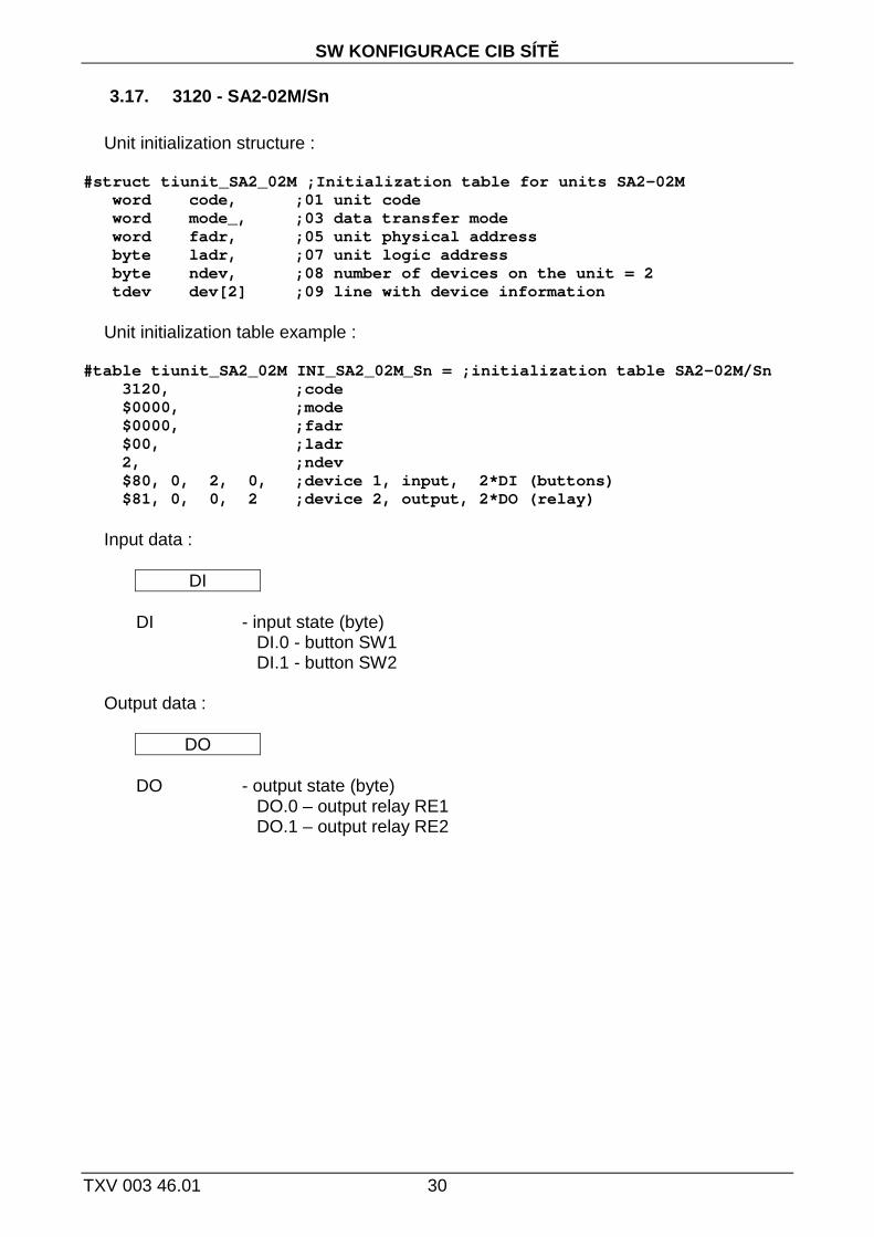
Input data :
DI DI - input state (byte) DI.0 - button SW1 DI.1 - button SW2 Output data :
DO DO - output state (byte) DO.0 – output relay RE1 DO.1 – output relay RE2

3. INELS UNITS DECLARATION
31 TXV 003 46.01 .
3.18. 3121 - SA2-04M/Ni
Unit initialization structure :
#struct tiunit_SA2_04M ;Initialization table for un its SA2-04M word code, ;01 unit code word mode_, ;03 data transfer mode word fadr, ;05 unit physical address byte ladr, ;07 unit logic address byte ndev, ;08 number of devices on the unit = 2 tdev dev[2] ;09 line with device information
Unit initialization table example :
#table tiunit_SA2_04M INI_SA2_04M_Ni = ;initializat ion table SA2-04M/Ni 3121, ;code $0000, ;mode $0000, ;fadr $00, ;ladr 2, ;ndev $80, 0, 4, 0, ;device 1, input, 4*DI (button s) $81, 0, 0, 4 ;device 2, output, 4*DO (relay)
Input data :
DI DI - input state (byte) DI.0 - button SW1 DI.1 - button SW2 DI.2 - button SW3 DI.3 - button SW4 Output data :
DO DO - output state (byte) DO.0 – output relay RE1 DO.1 - output relay RE2 DO.2 - output relay RE3 DO.3 - output relay RE4

SW KONFIGURACE CIB SÍTĚ
TXV 003 46.01 32
3.19. 3122 - SA2-04M/Sn
Unit initialization structure :
#struct tiunit_SA2_04M ;Initialization table for un its SA2-04M word code, ;01 unit code word mode_, ;03 data transfer mode word fadr, ;05 unit physical address byte ladr, ;07 unit logic address byte ndev, ;08 number of devices on the unit = 2 tdev dev[2] ;09 line with device information
Unit initialization table example :
#table tiunit_SA2_04M INI_SA2_04M_Sn = ;initializat ion table SA2-04M/Sn 3122, ;code $0000, ;mode $0000, ;fadr $00, ;ladr 2, ;ndev $80, 0, 4, 0, ;device 1, input, 4*DI (button s) $81, 0, 0, 4 ;device 2, output, 4*DO (relay)
Input data :
DI DI - input state (byte) DI.0 - button SW1 DI.1 - button SW2 DI.2 - button SW3 DI.3 - button SW4 Output data :
DO DO - output state (byte) DO.0 – output relay RE1 DO.1 - output relay RE2 DO.2 - output relay RE3 DO.3 - output relay RE4

3. INELS UNITS DECLARATION
33 TXV 003 46.01 .
3.20. 3123 - SOPHY2
Unit initialization structure :
#struct tiunit_SOPHY2 ;Initialization table for uni ts SOPHY2 word code, ;01 unit code word mode_, ;03 data transfer mode word fadr, ;05 unit physical address byte ladr, ;07 unit logic address byte ndev, ;08 number of devices on the unit = 5 tdev dev[5], ;09 line with device information word tempOfs, ; offset of the thermometer [0. 01°C] byte lang ; language mutation ; 0 - english ; 1 - czech ; 2 - german ; 3 - russian
Unit initialization table example :
#table tiunit_SOPHY2 INI_SOPHY2 = ;initialization t able SOPHY2 3123, ;code $0000, ;mode $0000, ;fadr $00, ;ladr 5, ;ndev $83, 0, 6, 2, ;device 1, in/out, 6*DI, 2*LED (2*button+4*DI) $80, 0, 16, 0, ;device 2, in, 1*AI (th ermometer) $80, 0, 8, 0, ;device 3, in, 1*LI (i lluminance) $83, 0, 24, 24, ;device 4, in/out, 1*IRin/out (infra)
$83, 0, 16, 16, ;device 5, in/out, 1*VOICEin/out (voice) 0, ;offset of the thermometer 1 ;czech language mutation
Input data :
DI Temp LI IRin VOICEin
DI - input state (byte) DI.0 - button UP DI.1 - button DOWN DI.2 - input IN1 DI.3 - input IN2 DI.4 - input IN3 DI.5 - input IN4
Temp - temperature (word) [0.01°C] LI - illuminance (byte) [0-255] (0 = low, 255 = high intensity) IRin - infra receiver (3*byte)
STAT (byte) – status byte STAT.5 - ACOut - alternating receiver bit (code sent) STAT.6 - TC1 – received infra code type STAT.7 - TC2 – received infra code type 0 0 - standard RC5

SW KONFIGURACE CIB SÍTĚ
TXV 003 46.01 34
0 1 - standard SIRCS 1 0 - standard NEC
CODE (word) – received infra code (Low, High) VOICEin - voice receiver (word) .0 - busy - SOPHY is busy .1 - listen - SOPHY is in monitoring status .5 - operationERROR - operation error .6 - operationOK - operation OK .7 - command - received voice command .8 - .15 - MsgCode - received voice command code
Output data :
DO IRout VOICEout DO - output state (byte) DO.0 - indication LED red DO.1 - indication LED green
IRout - infra transmitter (3*byte) CONT (byte) - control byte
CONT.5 - ACOut – alternating transmitter bit (send code) CONT.6 - TC1 – sent infra code type CONT.7 - TC2 – sent infra code type 0 0 - standard RC5 0 1 - standard SIRCS 1 0 - standard NEC
CODE (word) – aired infra code (Low, High) VOICEout - voice transmitter (word)
.0 - .7 - operationCODE - operation code = 0x00 – no operation = 0x01 – say standard message = 0x03 – delete all learnt commands = 0x04 - listening mode = 0x12 – learning command
.8 - .15 - MsgCode - code of sent/learnt command

3. INELS UNITS DECLARATION
35 TXV 003 46.01 .
3.21. 3124 – SOPHY2-L
Unit initialization structure :
#struct tiunit_SOPHY2_L ;Initialization table for u nits SOPHY2-L word code, ;01 unit code word mode_, ;03 data transfer mode word fadr, ;05 unit physical address byte ladr, ;07 unit logic address byte ndev, ;08 number of devices on the unit = 4 tdev dev[4], ;09 line with device information word tempOfs ; offset of the thermometer [0.0 1°C]
Unit initialization table example :
#table tiunit_SOPHY2_L INI_SOPHY2_L = ;initializati on table SOPHY2-L 3124, ;code $0000, ;mode $0000, ;fadr $00, ;ladr 4, ;ndev $83, 0, 6, 2, ;device 1, in/out, 6*DI, 2*LED (2*button+4*DI) $80, 0, 16, 0, ;device 2, in, 1*AI (th ermometer) $80, 0, 8, 0, ;device 3, in, 1*LI (i lluminance) $83, 0, 24, 24, ;device 4, in/out, 1*IRin/out (infra)
0 ;offset of the thermometer
Input data :
DI Temp LI IRin DI - input state (byte) DI.0 - button UP DI.1 - button DOWN DI.2 - input IN1 DI.3 - input IN2 DI.4 - input IN3 DI.5 - input IN4
Temp - temperature (word) [0.01°C] LI - illuminance (byte) [0-255] (0 = low, 255 = high intensity) IRin - infra receiver (3*byte)
STAT (byte) - status byte STAT.5 - ACOut – alternating transmitter bit (code sent) STAT.6 - TC1 – received infra code type STAT.7 - TC2 – received infra code type 0 0 - standard RC5 0 1 - standard SIRCS 1 0 - standard NEC
CODE (word) – received infra code (Low, High)

SW KONFIGURACE CIB SÍTĚ
TXV 003 46.01 36
Výstupní data :
DO IRout DO - output state (byte) DO.0 - indication LED red DO.1 - indication LED green
IRout - infra transmitter (3*byte) CONT (byte) - control byte
CONT.5 - ACOut – alternating transmitter bit (send code) CONT.6 - TC1 – sent infra code type CONT.7 - TC2 – sent infra code type 0 0 - standard RC5 0 1 - standard SIRCS 1 0 - standard NEC
CODE (word) – aired infra code (Low, High)

3. INELS UNITS DECLARATION
37 TXV 003 46.01 .
3.22. 3125 - WSB2-20
Unit initialization structure :
#struct tiunit_WSB2_20 ;Initialization table for un its WSB2-20 word code, ;01 unit code word mode_, ;03 data transfer mode word fadr, ;05 unit physical address byte ladr, ;07 unit logic address byte ndev, ;08 number of devices on the unit = 3 tdev dev[3], ;09 line with device information word tempOfs ; offset of the thermometer [0.0 1°C]
Unit initialization table example :
#table tiunit_WSB2_20 INI_WSB2_20 = ;initialization table WSB2-20 3125, ;code $0000, ;mode $0000, ;fadr $00, ;ladr 3, ;ndev $80, 0, 2, 0, ;device 1, input, 2*DI (button s) $81, 0, 0, 2, ;device 2, output, 2*DO (LED) $80, 0, 16, 0, ;device 3, input, 1*AI (therm ometer) 0 ;offset of the thermometer
Input data :
DI Temp DI - input state (byte) DI.0 - button 1 - UP DI.1 - button 2 - DOWN
Temp - temperature (word) [0.01°C] Output data :
DO DO - output state (byte) DO.0 - LED1 - green DO.1 - LED2 - red

SW KONFIGURACE CIB SÍTĚ
TXV 003 46.01 38
3.23. 3126 - WSB2-40
Unit initialization structure :
#struct tiunit_WSB2_40 ;Initialization table for un its WSB2-40 word code, ;01 unit code word mode_, ;03 data transfer mode word fadr, ;05 unit physical address byte ladr, ;07 unit logic address byte ndev, ;08 number of devices on the unit = 3 tdev dev[3], ;09 line with device information word tempOfs ; offset of the thermometer [0.0 1°C]
Unit initialization table example :
#table tiunit_WSB2_40 INI_WSB2_40 = ;initialization table WSB2-40 3126, ;code $0000, ;mode $0000, ;fadr $00, ;ladr 3, ;ndev $80, 0, 4, 0, ;device 1, input, 4*DI (button s) $81, 0, 0, 4, ;device 2, output, 4*DO (LED) $80, 0, 16, 0, ;device 3, input, 1*AI (therm ometer) 0 ;offset of the thermometer
Input data :
DI Temp DI - input state (byte) DI.0 - button 1 - UP DI.1 - button 2 - DOWN DI.2 - button 3 - UP DI.3 - button 4 - DOWN
Temp - temperature (word) [0.01°C] Output data :
DO DO - output state (byte) DO.0 - LED1 - green DO.1 - LED2 - red DO.2 - LED3 - green DO.3 - LED4 - red

3. INELS UNITS DECLARATION
39 TXV 003 46.01 .
3.24. 3127 - WSB2-80
Unit initialization structure :
#struct tiunit_WSB2_80 ;Initialization table for un its WSB2-80 word code, ;01 unit code word mode_, ;03 data transfer mode word fadr, ;05 unit physical address byte ladr, ;07 unit logic address byte ndev, ;08 number of devices on the unit = 3 tdev dev[3], ;09 line with device information word tempOfs ; offset of the thermometer [0.0 1°C]
Unit initialization table example :
#table tiunit_WSB2_80 INI_WSB2_80 = ;initialization table WSB2-80 3127, ;code $0000, ;mode $0000, ;fadr $00, ;ladr 3, ;ndev $80, 0, 8, 0, ;device 1, input, 8*DI (button s) $81, 0, 0, 8, ;device 2, output, 8*DO (LED) $80, 0, 16, 0, ;device 3, input, 1*AI (therm ometer) 0 ;offset of the thermometer
Input data :
DI Temp
DI - input state (byte) DI.0 - button 1 - UP DI.1 - button 2 - DOWN DI.2 - button 3 - UP DI.3 - button 4 - DOWN DI.4 - button 5 - UP DI.5 - button 6 - DOWN DI.6 - button 7 - UP DI.7 - button 8 - DOWN
Temp - temperature (word) [0.01°C]
Output data :
DO
DO - output state (byte) DO.0 - LED1 - green DO.1 - LED2 - red DO.2 - LED3 - green DO.3 - LED4 - red DO.4 - LED5 - green DO.5 - LED6 - red DO.6 - LED7 - green DO.7 - LED8 - red

SW KONFIGURACE CIB SÍTĚ
TXV 003 46.01 40
3.25. 3128 – MI2-02M
Unit initialization structure :
#struct tiunit_MI2_02M ;Initialization table for un its MI2-02M word code, ;01 unit code word mode_, ;03 data transfer mode word fadr, ;05 unit physical address byte ladr, ;07 unit logic address byte ndev, ;08 number of devices on the unit = 1 tdev dev[1] ;09 line with device information
Unit initialization table example :
#table tiunit_MI2_02M INI_MI2_02M = ;initialization table MI2-02M 3128, ;code $0000, ;mode $0000, ;fadr $00, ;ladr 1, ;ndev $C0, 0, 16, 0 ;device 1, input, 1*AI (voltag e)
Input data :
AI AI1) - Input voltage PSM (word) [0.01V] 1) Variable AI is relevant for internal master units only within the CPU CP-1004 and
CU2-01M. External master unit PSM does not contain input and in the variable AI the value 0 is transferred.

3. INELS UNITS DECLARATION
41 TXV 003 46.01 .
3.26. 3129 – FCC2-01
Unit initialization structure :
#struct tiunit_FCC2_01 ;Initialization table for un its FCC2-01 word code, ;01 unit code word mode_, ;03 data transfer mode word fadr, ;05 unit physical address byte ladr, ;07 unit logic address byte ndev, ;08 numbre of devices on the unit = 3 tdev dev[4], ;09 line with device information word tempOfs ; offset of the external therm ometer in 0.01°C
Unit initialization table example :
#table tiunit_FCC2_01 INI_FCC2_01 = ;initialization table FCC2-01 3129, ;code $0000, ;mode $0000, ;fadr $00, ;ladr 4, ;ndev $81, 0, 0, 8, ;device 1, output, 1*AO (fan turns) $81, 0, 0, 2, ;device 2, output, 2*DO (rela y) $80, 0, 16, 0, ;device 3, input, 1*AI (exte rnal thermometer) $80, 0, 16, 0, ;device 4, input, 1*AI (inte rnal thermometer) 0 ;offset of the external therm ometer
Input data :
Temp1 Temp2
Temp1 - external temperature (word) [0.01°C] Temp2 - internal temperature (word) [0.01°C]
Output data :
AO DO AO - fan turns (byte) [0-100%] DO - status of binary outputs (byte) DO.0 - output 1 DO.1 - output 2

SW KONFIGURACE CIB SÍTĚ
TXV 003 46.01 42
3.27. 3133 – WMR2-11
Unit initialization structure :
#struct tiunit_WMR2_11;Initialization table for uni ts WMR2-11 word code, ;01 unit code word mode_, ;03 data transfer mode word fadr, ;05 unit physical address byte ladr, ;07 unit logic address byte ndev, ;08 number of devices on the unit = 4 tdev dev[4], ;09 line with device information word tempOfs ; offset of the thermometer in 0.01°C
Unit initialization table example :
#table tiunit_WMR2_11 INI_WMR2_11 = ;initialization table WMR2-11 3133, ;code $0000, ;mode $0000, ;fadr $00, ;ladr 4, ;ndev $80, 0, 2, 0, ;device 1, input, 2*DI (bu ttons) $80, 0, 40, 0, ; device 2, vstupni, 1*CARD (5B karta) $81, 0, 0, 4, ; device 3, output, 4*DO (2 LED, 1DO, 1buzzer) $80, 0, 16, 0, ; device 4, input, 1*AI (the rmometer in centigrades°C) 0 ;offset of the thermometer
Input data :
DI CARD Temp
DI - output state (byte) DI.0 - button UP DI.1 - button DOWN CARD - card code (5*byte)
Temp - temperature (word) [0.01°C]
Output data :
DO
DO - output state (byte) DO.0 - LED1 - green DO.1 - LED2 - red DO.2 - relay DO.3 - buzzer

3. INELS UNITS DECLARATION
43 TXV 003 46.01 .
3.28. 3143 – WSB2-60
Unit initialization structure :
#struct tiunit_WSB2_60 ;Initialization table for un its WSB2-60 word code, ;01 unit code word mode_, ;03 data transfer mode word fadr, ;05 unit physical address byte ladr, ;07 unit logic address byte ndev, ;08 number of devices on the unit = 3 tdev dev[3], ;09 line with device information word tempOfs ; offset of the thermometer [0.0 1°C]
Unit initialization table example :
#table tiunit_WSB2_60 INI_WSB2_60 = ;initialization table WSB2-60 3143, ;code $0000, ;mode $0000, ;fadr $00, ;ladr 3, ;ndev $80, 0, 6, 0, ;device 1, output, 6*DI (butto ns) $81, 0, 0, 14, ;device 2, output,12*DO (LED) $80, 0, 16, 0, ;device 3, input, 1*AI (therm ometer) 0 ;offset of the thermometer
Input data :
DI Temp
DI - input state (byte) DI.0 - button 1 - UP DI.1 - button 2 - DOWN DI.2 - button 3 - UP DI.3 - button 4 - DOWN DI.4 - button 5 - UP DI.5 - button 6 - DOWN
Temp - temperature (word) [0.01°C]
Output data :
DO
DO - output state (byte) DO.0 - LED1 – green : DO.5 - LED6 – green DO.8 – LED1 – red : DO.13 – LED6 - red

SW KONFIGURACE CIB SÍTĚ
TXV 003 46.01 44
3.29. 3148– ADC2-40M
Unit initialization structure :
#struct tiunit_ADC2_40M ;Initialization table for u nits ADC2-40M word code, ;01 unit code word mode_, ;03 data transfer mode word fadr, ;05 unit physical address byte ladr, ;07 unit logic address byte ndev, ;08 number of devices on the unit = 5 tdev dev[5], ;09 line with device information byte aitype[4], ; input type AIx byte aitau[4] ; input filtration constant AIx
Items aitype can take following values:
0x20 - Pt100, W100 = 1,385, -90/+320°C 0x21 - Pt100, W100 = 1,391, -90/+320°C 0x22 - Pt1000 , W100 = 1,385, -90/+320°C 0x23 - Pt1000, W100 = 1,391, -90/+320°C 0x24 - Ni1000, W100 = 1,617, -60/+200°C 0x25 - Ni1000, W100 = 1,500, -60/+200°C 0x27 - OV1000 0x28 - NTC 12k (negative thermistor, 12kΩ at 25°C), -40/+125°C 0x40 - 0 ÷ 20 mA 0x41 - 4 ÷ 20 mA 0x80 - 0 ÷ 10 V 0x81 - 0 ÷ 5 V 0x82 - 0 ÷ 2 V 0x83 - 0 ÷ 1 V 0x84 - 0 ÷ 0,5 V
Unit initialization table example :
#table tiunit_ADC2_40M INI_ADC2_40M = ;initializati on table ADC2-40M 3148, ;code $0000, ;mode $0000, ;fadr $00, ;ladr 5, ;ndev $80, 0, 8, 0, ;device 1, input, STAT (state AIx) $80, 0, 16, 0, ;device 2, input, AI1 $80, 0, 16, 0, ;device 3, input, AI2 $80, 0, 16, 0, ;device 4, input, AI3 $80, 0, 16, 0, ;device 5, input, AI4 $24,$24,$24,$24, ;type AIx 0, 0, 0, 0 ;filtration AIx (0..255 = 0..25, 5s)
3. INELS UNITS DECLARATION
45 TXV 003 46.01 .
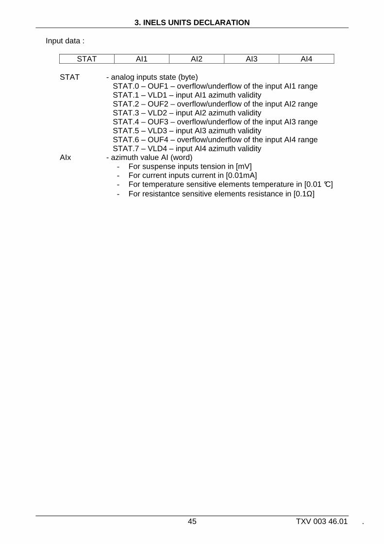
Input data :
STAT AI1 AI2 AI3 AI4 STAT - analog inputs state (byte) STAT.0 – OUF1 – overflow/underflow of the input AI1 range STAT.1 – VLD1 – input AI1 azimuth validity STAT.2 – OUF2 – overflow/underflow of the input AI2 range STAT.3 – VLD2 – input AI2 azimuth validity STAT.4 – OUF3 – overflow/underflow of the input AI3 range STAT.5 – VLD3 – input AI3 azimuth validity STAT.6 – OUF4 – overflow/underflow of the input AI4 range STAT.7 – VLD4 – input AI4 azimuth validity AIx - azimuth value AI (word)
- For suspense inputs tension in [mV] - For current inputs current in [0.01mA] - For temperature sensitive elements temperature in [0.01 °C] - For resistantce sensitive elements resistance in [0.1Ω]

SW KONFIGURACE CIB SÍTĚ
TXV 003 46.01 46
3.30. 3149 – IM2-20B
Unit initialization structure :
#struct tiunit_IM2_20B ;Initialization table for un its IM2-20B word code, ;01 unit code word mode_, ;03 data transfer mode word fadr, ;05 unit physical address byte ladr, ;07 unit logic address byte ndev, ;08 number of devices on the unit = 2 tdev dev[2], ;09 line with device information byte enbEZS, ; configuration of binary inputs 0-1 of the unit ; .x = 0/1 = input .x configured as DI/EZS byte typEZS, ; type of balancing EZS input 0- 1 of the unit
; .x = 0/1 = input .x is single/double ;balanced word tempOfs ; offset of the thermometer [0. 01°C]
Unit initialization table example :
#table tiunit_IM2_20B INI_IM2_20B = ;initialization table IM2-20B 3149, ;code $0000, ;mode $0000, ;fadr $00, ;ladr 2, ;ndev $80, 0, 10, 0, ;device 1, input, 2*DI (2*DI/E ZS) $80, 0, 16, 0, ;device 2, input, 1*AI (therm ometer) $03, ;inputs configured for EZS $03, ;EZS inputs double balanced 0 ;offset of the thermometer
Input data :
DI TAMP Temp DI - input state (byte) DI.0 - input 0 DI.1 - input 1 TAMP - signalization of the „tamper“ status of balanced EZS inputs (byte) TAMP.0 - tamper status of EZS input 0 TAMP.1 - tamper status of EZS input 1
Temp - temperature (word) [0.01°C]

3. INELS UNITS DECLARATION
47 TXV 003 46.01 .
3.31. 3150- IM2-40B
Unit initialization structure :
#struct tiunit_IM2_40B ;Initialization table for un its IM2-40B word code, ;01 unit code word mode_, ;03 data transfer mode word fadr, ;05 unit physical address byte ladr, ;07 unit logic address byte ndev, ;08 number of device on the unit = 2 tdev dev[2], ;09 line with device information byte enbEZS, ; configuration of binary inputs 0-3 of the unit ; .x = 0/1 = input .x configured as DI/EZS byte typEZS, ; type of balancing of EZS input 0-3 of the unit
; .x = 0/1 = input .x is single/double ;balanced word tempOfs ; offset of the thermometer [0. 01°C]
Unit initialization table example :
#table tiunit_IM2_40B INI_IM2_40B = ;initialization table IM2-40B 3150, ;code $0000, ;mode $0000, ;fadr $00, ;ladr 2, ;ndev $80, 0, 10, 0, ;device 1, input, 4*DI (2*DI/E ZS + 2DI) $80, 0, 16, 0, ;device 2, input, 1*AI (therm ometer) $03, ;inputs configured for EZS $03, ;EZS inputs double, balanced 0 ;offset of the thermometer
Input data :
DI TAMP Temp DI - inputs state (byte) DI.0 - input 0 DI.1 - input 1 DI.2 - input 2 DI.3 - input 3 TAMP - signalization of „tamper“ status of balanced EZS inputs (byte) TAMP.0 - tamper status of EZS input 0 TAMP.1 - tamper status of EZS input 1
Temp - temperature (word) [0.01°C]

SW KONFIGURACE CIB SÍTĚ
TXV 003 46.01 48
3.32. 3691- DIM6
Unit initialization structure :
#struct tiunit_DIM6 ;Initialization table for uni ts DIM6 word code, ;01 unit type word mode_, ;03 data transfer mode word fadr, ;05 unit physical address byte ladr, ;07 unit logic address byte ndev, ;08 number of devices on the unit = 3 tdev dev[3], ;09 line with device information word tempOfs ; offset of the thermometer in 0.01°C
Unit initialization table example :
#table tiunit_DIM6 INI_DIM6 = ;initialization table DIM6 3691, ;code $0000, ;mode $0000, ;fadr $00, ;ladr 3, ;ndev $80, 0, 8, 0, ;device 1, input, 1*Stat (st atus) $81, 0, 0, 8, ;device 2, output, 1*AO (0- 100%) $80, 0, 16, 0, ;device 3, input, 1*AI(therm ometer in centigrades °C)
0 ;offset of the thermometer
Input data :
Stat Temp
Stat - dimmer state (byte) .0 - overheating .1 - overloading .2 – unspecified overloade type .3 – fan run
Temp - temperature (word) [0.01°C]
Output data :
AO AO - analog output value (byte) [0-100%]

Poznámky
49 TXV 003 46.01 .
Notes :

Poznámky
TXV 003 46.01 50
Notes :

.
Objednávky a informace:Teco a. s. Havlíčkova 260, 280 58 Kolín 4, tel. 321 737 611, fax 321 737 633
TXV 003 46.01
Výrobce si vyhrazuje právo na změny dokumentace. Poslední aktuální vydání je k dispozici na internetu
www.tecomat.cz