SURVEY MANUAL - MRWAmrwa.com.au/Documents/Standards/Survey Manual.pdf · Survey Manual Third...
565
Survey Manual Third Edition No.
Transcript of SURVEY MANUAL - MRWAmrwa.com.au/Documents/Standards/Survey Manual.pdf · Survey Manual Third...

Survey Manual
Third Edition No.

Copyright Yarra Valley Water Ltd. © 1998 Copyright South East Water Ltd. © 1998 Copyright City West Water Ltd. © 1998 All rights reserved. This publication is protected by copyright and is provided under licence. Permission is granted for registered users to copy the “As-constructed Record – Water Supply” form (blank) and the “As-constructed Record – Sewer” field note (blank) for dealings with the three Water Companies. No other Part of this publication should be reproduced, distributed, transmitted, stored in a retrieval system or reduced to any electronic medium. The Water Companies assume no responsibility for any errors that may appear in this document or any damages arising out of the use or inability to use this document. Changes may be made periodically to the information herein. July 1998

Survey Manual Third Edition 01/07/98 iii
Table of Contents About this Manual v Intended audience v Related reference material vi Definitions vii Part 1 Survey Responsibilities Chapter 1 Survey Responsibilities 1 General 1-1 1.1 Water Company 1-1 1.2 Consultant 1-1 1.3 Surveyor 1-2 1.3.1 Prior to the commencement of Works 1-2 1.3.2 During construction of the Works 1-3 1.3.3 Upon completion of the Works 1-3 Part 2 Survey Requirements Chapter 2 Subdivisional Information 2 General 2-1 2.1 AMG control of subdivisional information 2-1 2.2 Supply of subdivisional information 2-2 2.2.1 Plan of subdivision 2-2 2.2.2 Subdivisional digital data 2-2 Chapter 3 Survey Control 3 General 3-1 3.1 Horizontal control 3-1 3.2 Vertical control 3-1 3.3 AMG and AHD marks 3-2 Chapter 4 Recording and Supply of As-constructed information 4 General 4-1 4.1 Recording of as-constructed information 4-1 4.2 Supply of as-constructed information 4-2
iv Third Edition 01/07/09 Survey Manual
Part 3 As-constructed Information Chapter 5 Water Supply 5 General 5-1 5.1 Vertical position 5-1 5.2 Horizontal position 5-1 5.3 Details to be recorded for water supply 5-2 5.3.1 Other details to be recorded 5-2 5.3.2 Horizontal and vertical position checks 5-3
Chapter 6 Sewerage 6 General 6-1 6.1 Access Chambers (manholes) 6-1 6.1.1 Details to be recorded for manholes 6-2 6.2 Inspection Shafts and Maintenance Shafts 6-3 6.3 Pipe Junctions 6-3 6.4 Ends of Pipe and Reducers 6-4 6.5 Pipe Sections 6-4 6.5.1 Grade checks 6-5 6.5.2 Details to be recorded for pipe sections 6-5 6.6 Curved Sewers 6-6 6.6.1 Vertically curved sewers 6-6 6.6.2 Horizontally curved sewers 6-7 6.7 Property Branch Sewers (connections) 6-7 6.7.1 Other details to be recorded for connections 6-9 6.8 Other sewerage details to be recorded 6-10
Chapter 7 Pumping Stations and Rising Mains 7 General 7-1 7.1 Pumping stations 7-1 7.2 Rising mains 7-2 Part 4 Appendices Appendix A Sewer A-1 Appendix B Access Chambers B-1 Appendix C Access Chambers C-1 Appendix D Gas Check Chambers D-1 Appendix E Property Branch Sewers E-1 Appendix F Property Branch Sewers F-1 Appendix G Inspection Shafts (and Maintenance Shafts) G-1 Appendix H As-constructed Record - Sewer field note (blank) H-1 Appendix I As-constructed Record - Water Supply form (blank) I-1 Survey Verification Forms
Survey Manual Third Edition 01/07/98 v
About this Manual
This Manual describes the responsibilities and requirements for the survey of water supply and sewerage Works and the supply of related information to the Water Company.
Part 1
Describes the survey responsibilities of the Water Company, the Consultant and the Surveyor.
Part 2
Describes the survey requirements for the supply of as-constructed information and the supply of related subdivisional and survey control information to the Water Company.
Part 3
Describes the as-constructed information to be recorded and supplied to the Water Company.
Part 4
Indicates with diagrams the as-constructed information to be recorded.
Intended audience This Manual has been written for engineering and survey consultants and the Water Company staff.

vi Third Edition 01/07/98 Survey Manual
Related reference material
The following documents should be referred to in conjunction with this document:
• Water Company Policy and Pricing Manual
• National Sewerage Code
• National Water Supply Code
• Local safety requirements for work in sewers and confined spaces
• Water Company Quality Assurance Requirements
The following documents are also referred to or are relevant to this Manual:
• Occupational Health and Safety Act 1985
• Subdivision Act 1988
• Subdivision (Procedures) Regulations 1989
• Survey Co-ordination Act 1958
• Survey Co-ordination (Surveys) Regulations 1992
• Surveyors Act 1978
• Surveyors (Cadastral Surveys) Regulations 1995
• Survey Practice Handbook, Volume 2
Survey Manual Third Edition 01/07/98 vii
Definitions
The Water Company The Authority or Agency to whom the water supply,
sewerage and associated Works are to be vested or officers appointed to act on behalf of the Water Company.
Consultant A person or Agency engaged to undertake the design, construction and or survey of water supply and sewerage Works.
Surveyor Either a Licensed Surveyor or a person whose qualifications and experience are appropriate for the survey requirements of the Works.
Nominated The Consultants representative whose Representative qualifications and experience are appropriate for them to act as the responsible agent for the Works.
Contractor The Agency engaged to undertake the Works.
Works The construction of water supply and or sewerage infrastructure to be vested in the Water Company.
Design Plans Drawings of the Works prepared in accordance with the Water Supply Design Manual, Sewerage Design Manual and Survey Manual.
Licensed Surveyor A Surveyor registered and endorsed under the Surveyors Act 1978.
OSG Office of the Surveyor General.
Verification Form Applicable to Consultants with accreditation to ISO
9001 or accreditation acceptable to the Water Company.


Part 1 Survey Responsibilities

Survey Manual Third Edition 01/07/98 1-1
Chapter 1 Survey Responsibilities
1 General This Part of the Survey Manual describes the survey responsibilities of the Water Company, the Consultant and the Surveyor for the provision of water supply and sewerage Works by Agreement.
1.1. Water Company The Water Company is responsible for:
I. Determining the standards for survey.
II. Determining the acceptance requirements.
III. The quality management of the asset records.
IV. Undertaking quality audits.
V. Establishing the tolerances and requirements for the survey and supply of as-constructed information and other related information to the Water Company.
1.2 Consultant The Consultant shall:
I. Appoint a Surveyor (or Surveyor’s) to provide the survey requirements for the Works.
II. Ensure that the required subdivisional information is forwarded to the Water Company with the appropriate Verification Form at least five (5) working days prior to the commencement of Works.
III. Continued on next page …
1-2 Third Edition 01/07/98 Survey Manual
Consultant’s Responsibilities continued …
IV. Ensure that, if applicable, the Design Plans note the information relating to the Australian Map Grid (AMG) and Australian Height Datum (AHD) permanent marks obtained from the OSG and adopted as datum.
V. Ensure that, if applicable, the Design Plans note the survey control (marks) established for use during the construction, recording and auditing of Works and a copy of the Plans are forwarded to the Water Company at least five (5) working days prior to the commencement of construction.
VI. Ensure that the marks established for use during construction, recording and auditing purposes are maintained during construction.
VII. Ensure that sufficient title pegs are maintained during construction to enable auditing of the Works, i.e. pegs of close proximity to the Works.
VIII. Ensure that the as-constructed details of the Works are recorded and forwarded to the Water Company with the appropriate Verification Form.
1.3. Surveyor
1.3.1. Prior to the commencement of Works, the Surveyor shall:
i Connect the Works and related subdivision to permanent marks obtained from the Office of Surveyor General. A minimum of two (2) marks connected to AMG and two (2) marks connected to AHD are to be adopted as datum.
Exceptions may apply when a subdivision is of nine (9) lots or less and the Design Plans do not specify AMG co-ordinates or AHD levels (ref. Part 2 Requirements).
ii Provide the Consultant with all information relating to the permanent mark information adopted as datum (if applicable).
Continued on next page …

Survey Manual Third Edition 01/07/98 1-3
Surveyors Responsibilities continued …
iii Provide the required subdivision information to the Consultant.
iv Ensure that, if applicable, a minimum of three (3) AMG and or three (3) AHD marks are established in the Works area and or per stage of a subdivision and the information is forwarded to the Consultant.
Exceptions may apply when the Design Plans do not specify AMG co-ordinates or AHD levels (ref. Part 2 Requirements).
1.3.2 During construction of the Works, the Surveyor shall:
i Provide assistance in survey matters to the Nominated Representative.
ii Assume responsibility for the recording of the constructed Works within the tolerances and to the requirements established by the Water Company.
iii Liaise with the Contractor to ensure that:
• The as-constructed detail is recorded as the Works proceed.
• All recording of the as-constructed detail is completed before the commencement of backfilling.
iv Notify the Nominated Representative as soon as unsatisfactory variance is detected between the as-constructed detail and the Design Plans.
v Retain copies of all notices (related to the survey of the Works) for audit purposes.
1.3.3 Upon completion of the Works:
The Surveyor shall forward the as-constructed information to the Consultant.

Survey Manual Third Edition 01/07/98 1-4

Part 2 Survey Requirements

Survey Manual Third Edition 01/07/98 2-1
Chapter 2 Subdivisional Information
2 General The Licensed Surveyor is responsible for connecting the subdivision to the Australian Map Grid (AMG) in accordance with the requirements of the relevant legislation and the appropriate Authorities.
2.1 AMG control of subdivisional information For subdivisions of ten (10) lots or more the Surveyor shall supply the Consultant with the AMG co-ordinates of four (4) designated points on the title boundaries within the subdivision. Two of the four points are to be at opposite extremes of the subdivision and the other two points shall be evenly distributed.
Exceptions to this requirement include:
i Body corporate subdivisions
ii Subdivision of buildings
iii Subdivisions not requiring new Water Company services
iv Subdivisions of nine (9) lots or less that are not part of a staged development and are situated completely within established areas. Contact the Water Company for confirmation of whether the subdivision is within an established area.
2-2 Third Edition 01/07/98 Survey Manual
2.2 Supply of subdivisional information
2.2.1 Plan of subdivision
A hardcopy Plan of Subdivision is required for all developments and is to be forwarded to the Water Company. The Plan of Subdivision is to be certified by a Licensed Surveyor.
The Plan shall show:
i Details of the OSG marks adopted for AMG control of the subdivision.
ii AMG co-ordinates of four (4) designated points within the subdivision (ref. AMG control of subdivisional information).
2.2.2 Subdivisional digital data
If the development is of ten (10) lots or more the Plan of Subdivision shall also be submitted in digital format. The digital format shall be in accordance with the Subdivision Digital Input Manual.
The disk containing the digital data shall be:
i Labelled with the Suppliers name and the Plan of Subdivision number.
iii In either .DXF or MicroStation .DGN format.
Survey Manual Amended 1/3/2000 3-1
Chapter 3 Survey Control
3 General The Surveyor shall establish marks for the horizontal and vertical control of the Works. The marks are for use during the construction, recording and auditing of the Works.
Exceptions to this requirement may apply when:
i A development is of nine (9) lots or less, and
ii The Design Plans do not specify AMG co-ordinates or AHD levels.
3.1 Horizontal control The Surveyor shall establish three (3) marks connected to the Australian Map Grid (AMG) when the Design Plans specify AMG co-ordinates and or the development is of ten (10) lots or more.
The survey procedures adopted in determining the AMG co-ordinates of the marks shall ensure that the co-ordinates noted on the Design Plans will enable the Works to be constructed within the required tolerances (ref. Construction Specifications).
3.2 Vertical control The Surveyor shall establish three (3) marks connected to AHD when the Design Plans specify AHD levels and or the development is of ten (10) lots or more.
The surveyor shall establish a minimum of three (3) marks connected to AHD when the Design Plans specify AHD levels and the development is of ten (10) lots or more.
The surveyor shall establish a minimum of two (2) marks connected to AHD when the Design Plans specify AHD levels and the development is of nine lots or less.
3-2 Amended 1/3/2000 Survey Manual
The survey procedures adopted in determining the AHD levels of the marks shall ensure that the levels noted on the Design Plans will enable the Works to be constructed within the required tolerances (ref. Construction Specifications).
Exceptions may apply to the supply of vertical control and marks are not required for water supply works where AHD levels are specified or for sewer works when:
i A development is of nine (9) lots or less, and
ii The functional requirements of the works can be met without
reference to vertical control marks, and
iii The works consist of two (2) pipe sections or less (ie sewer access
point to access point or water main node to node), and
iv The total length of the works is less than 80 metres, and
v The works are unlikely to have effect apon future extensions.
3.3 AMG and AHD marks Marks established for AMG control can be the same as those marks established for AHD control.
The marks shall be:
i Spaced evenly over each stage of a subdivision or the Works area.
ii Of a stable nature, e.g. star picket or galvanised iron pipe driven flush with the ground, nail in concrete, etc,
iii Clearly marked in the field with a unique identifier.
iv Noted on the Design Plans with the unique identifier, the co-ordinates and or level (quoted to the nearest 0.01 metre) and sufficient information to enable the marks to easily located in the field, i.e. ties, description, etc,
Survey Manual Third Edition 01/07/98 4-1
Chapter 4 Recording and Supply of As-constructed Information
4 General The Surveyor is responsible for the recording of the constructed water supply and sewerage Works and the supply of as-constructed information to the Consultant.
4.1 Recording of as-constructed information
The Surveyor is responsible for the recording of:
i The horizontal and vertical position of the constructed water supply and sewerage pipes and associated Works.
ii Materials and other construction characteristics.
iii Information to enable the constructed Works to be compared to the Design Plans.
Refer to Part 3 “As-constructed Information” and Part 4 “Appendices” for details of information to be recorded.
The as-constructed position shall be related to:
i Pegged title boundaries and or AMG co-ordinates for horizontal (plan) position.
ii AHD for levels and or depth below finished surface if applicable.
The accuracy of surveys for the recording of as-constructed detail shall be sufficient to determine whether the constructed Works are within construction tolerances.
4-2 Third Edition 01/07/98 Survey Manual
4.2 Supply of as-constructed information
4.2.1 As-constructed details of the water supply and sewerage Works for subdivisions of ten (10) lots or more shall be supplied:
i In either .DXF or MicroStation .DGN digital format and in accordance with the Water Supply Digital Input Manual and Sewerage Digital Input Manual, and shall be
ii Accompanied by a hardcopy plan of the graphical information at a scale of 1:1000 for water supply and 1:500 for sewerage Works.
The disk containing the digital data and the accompanying plans shall be:labelled with the Supplier’s name and the Water Company reference number of the Works.
4.2.2 As-constructed details of the water supply Works for subdivisions of nine (9) lots or less shall be supplied:
i In either the formats as per (all of) 4.2.1, or
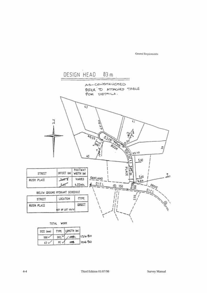
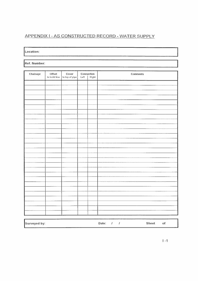
ii In the hardcopy formats of an “As-constructed Record - Water Supply” form and accompanying amended Design Plan (ref. pages 4-3 & 4-4).
4.2.3 As-constructed details of the sewerage Works for subdivisions of nine (9) lots or less shall be supplied:
i In either the formats as per (all of) 4.2.1, or
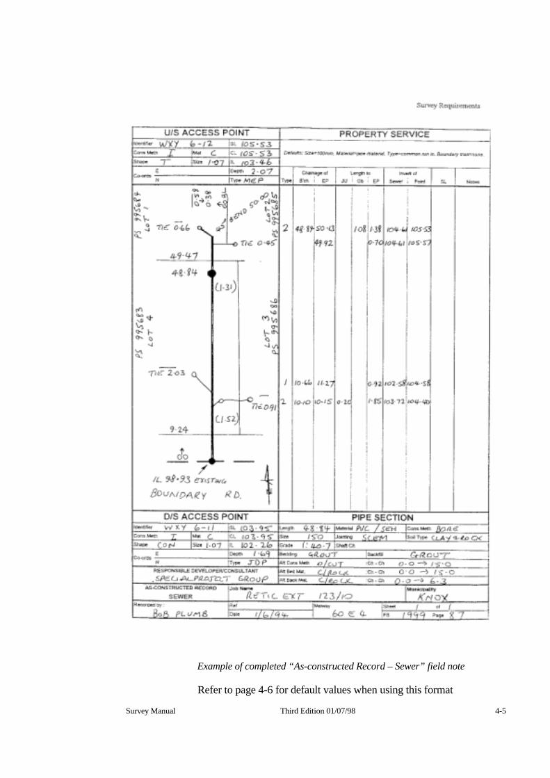
ii In the hardcopy format of an “As-constructed Record - Sewer” field note (ref. page 4-5).
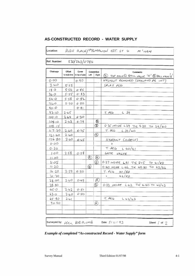
Survey Manual Third Edition 01/07/98 4-1
AS-CONSTRUCTED RECORD - WATER SUPPLY
Example of completed “As-constructed Record - Water Supply” form
4-4 Third Edition 01/07/98 Survey Manual
Survey Manual Third Edition 01/07/98 4-5
Example of completed “As-constructed Record – Sewer” field note
Refer to page 4-6 for default values when using this format
4-6 Third Edition 01/07/98 Survey Manual
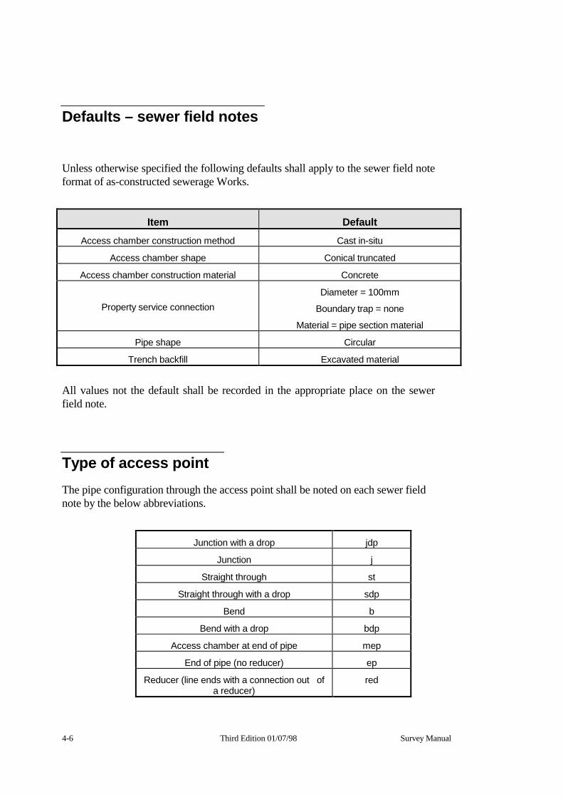
Defaults – sewer field notes
Unless otherwise specified the following defaults shall apply to the sewer field note format of as-constructed sewerage Works.
Item Default Access chamber construction method Cast in-situ
Access chamber shape Conical truncated
Access chamber construction material Concrete
Property service connection Diameter = 100mm
Boundary trap = none
Material = pipe section material
Pipe shape Circular
Trench backfill Excavated material
All values not the default shall be recorded in the appropriate place on the sewer field note.
Type of access point The pipe configuration through the access point shall be noted on each sewer field note by the below abbreviations.
Junction with a drop jdp
Junction j
Straight through st
Straight through with a drop sdp
Bend b
Bend with a drop bdp
Access chamber at end of pipe mep
End of pipe (no reducer) ep
Reducer (line ends with a connection out of a reducer)
red

Part 3 As-constructed Information

Survey Manual Third Edition 01/07/98 5.1
Chapter 5 Water Supply
5 General The Surveyor shall be responsible for the recording of the horizontal and vertical position of the water supply pipes and fittings and forwarding the information to the Consultant.
The following as-constructed details are required.
5.3 Vertical position Depths to top of pipe and or AHD invert levels shall be recorded at:
• Intersection of pipes
• Mid-points of curves
• Vertical bends
• Changes of grade
• Where the depth varies by more than 0.20 metre due to significant changes in surface level, e.g. road crossing, drain crossing, etc,
5.4 Horizontal position
AMG co-ordinates, running chainages and or offsets to title shall be recorded at:
• Horizontal bends
• Changes of grade
• Vertical bends
• Changes in direction
• Fittings
• Changes in pipe characteristics
• Property connections
5.2 Third Edition 01/07/98 Survey Manual
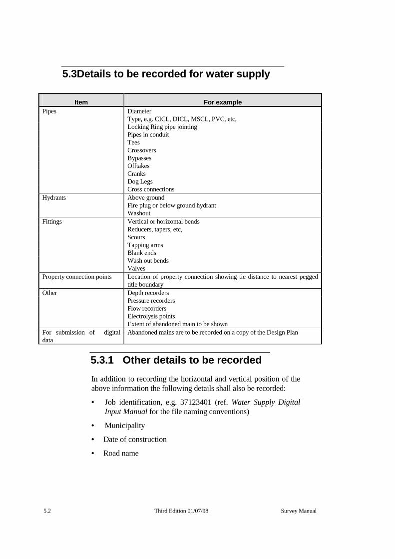
5.3Details to be recorded for water supply
Item For example Pipes Diameter Type, e.g. CICL, DICL, MSCL, PVC, etc, Locking Ring pipe jointing Pipes in conduit Tees Crossovers Bypasses Offtakes Cranks Dog Legs Cross connections Hydrants Above ground Fire plug or below ground hydrant Washout Fittings Vertical or horizontal bends Reducers, tapers, etc, Scours Tapping arms Blank ends Wash out bends Valves Property connection points Location of property connection showing tie distance to nearest pegged
title boundary Other Depth recorders Pressure recorders Flow recorders Electrolysis points Extent of abandoned main to be shown For submission of digital data
Abandoned mains are to be recorded on a copy of the Design Plan
5.3.1 Other details to be recorded In addition to recording the horizontal and vertical position of the above information the following details shall also be recorded:
• Job identification, e.g. 37123401 (ref. Water Supply Digital Input Manual for the file naming conventions)
• Municipality
• Date of construction
• Road name
As-constructed Information - Water Supply
Survey Manual Third edition 01/07/98 5-3
5.3.2 Horizontal and vertical position checks
It is recommended that the position and depth (or AHD level if applicable) of the water main pipes be checked at maximum intervals of 30 metres to ensure that construction meets the required tolerances. These checks are not required to be submitted to the Water Company.

5-4 Third Edition 01/07/98 Survey Manual
Survey Manual Third Edition 01/07/98 6-1
Chapter 6 Sewerage
6 General The Surveyor shall be responsible for the recording of the horizontal and vertical position of the sewer pipes and fittings and forwarding the information to the Consultant.
The following as-constructed details are required.
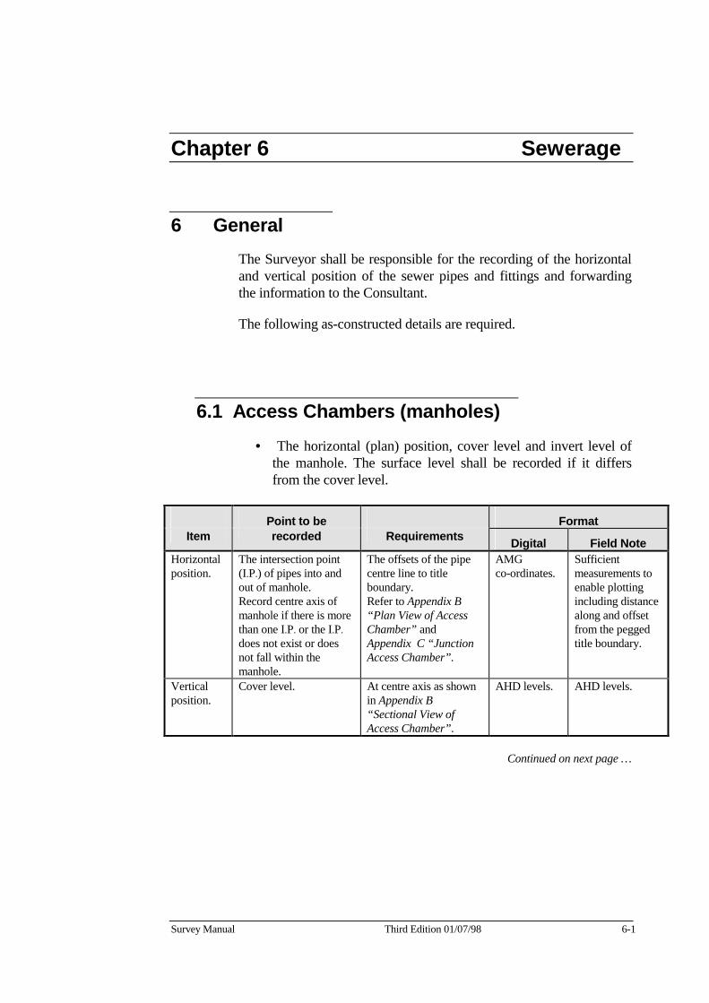
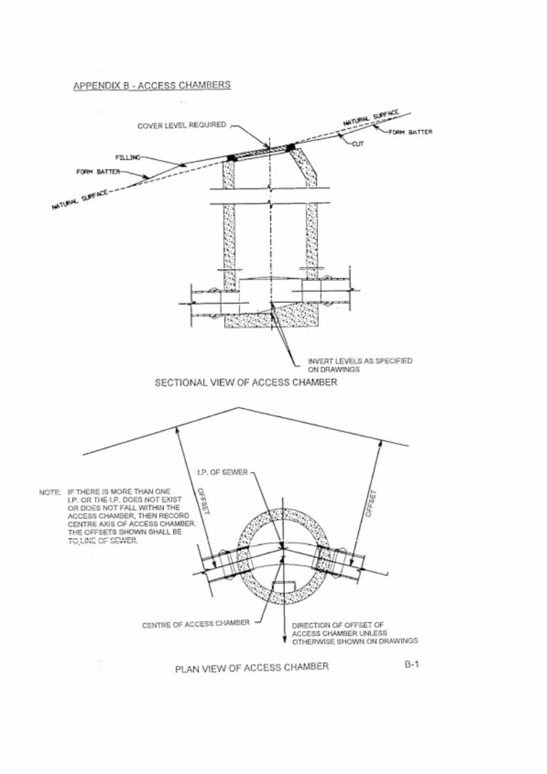
6.1 Access Chambers (manholes) • The horizontal (plan) position, cover level and invert level of
the manhole. The surface level shall be recorded if it differs from the cover level.
Point to be Format Item recorded Requirements Digital Field Note
Horizontal position.
The intersection point (I.P.) of pipes into and out of manhole. Record centre axis of manhole if there is more than one I.P. or the I.P. does not exist or does not fall within the manhole.
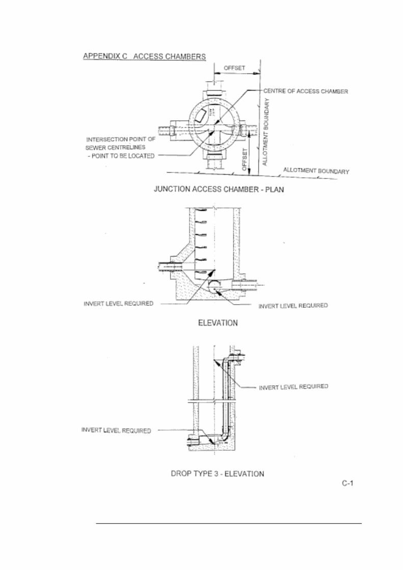
The offsets of the pipe centre line to title boundary. Refer to Appendix B “Plan View of Access Chamber” and Appendix C “Junction Access Chamber”.
AMG co-ordinates.
Sufficient measurements to enable plotting including distance along and offset from the pegged title boundary.
Vertical position.
Cover level. At centre axis as shown in Appendix B “Sectional View of Access Chamber”.
AHD levels. AHD levels.
Continued on next page …

6-2 Third Edition 01/07/98 Survey Manual
Manholes continued …
Point to be Format
Item recorded Requirements Digital Field Note
Vertical position (continued).
Invert levels.
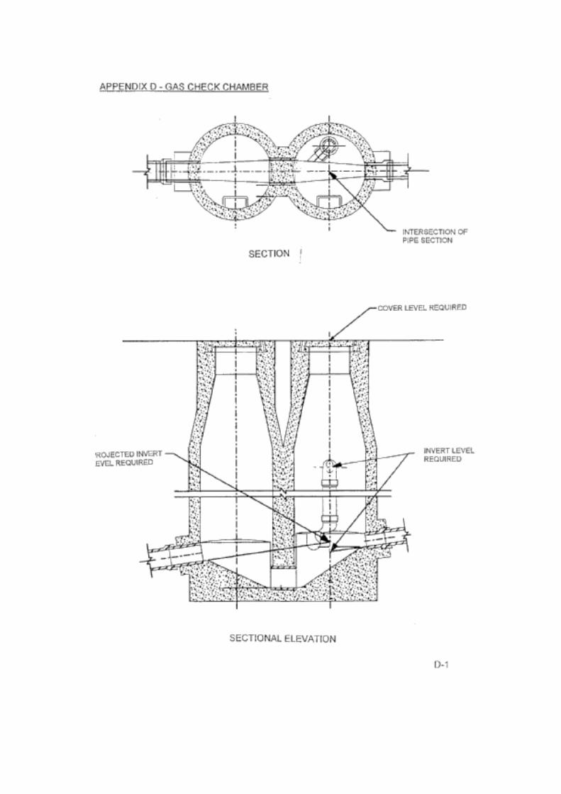
The invert level of all pipes (into and out of manhole) projected on grade to centre of manhole. Refer to Appendix B “Sectional View of Access Chamber”, Appendix C “Sectional Elevation” and Appendix D “Sectional Elevation”.
AHD levels.
AHD levels.
Future extension (stub pipe).
The invert level (and diameter) of the stub pipe.
AHD levels. AHD levels.
6.1.1Details to be recorded for manholes
Item For example
Size Internal diameter, e.g. 1070 mm, 1200 mm, etc,
Type Straight through, junction, drop, etc,
Internal shape Conical, truncated or circular
Material Construction material, e.g. concrete, polyethylene, etc,
Construction method Cast-in-situ or precast
Data of construction Date of installation
Unique identifier Obtained from the Water Company at the design stage, e.g. SNK26-20
As-constructed Information - Sewerage
Survey Manual Third Edition 01/07/98 6-3
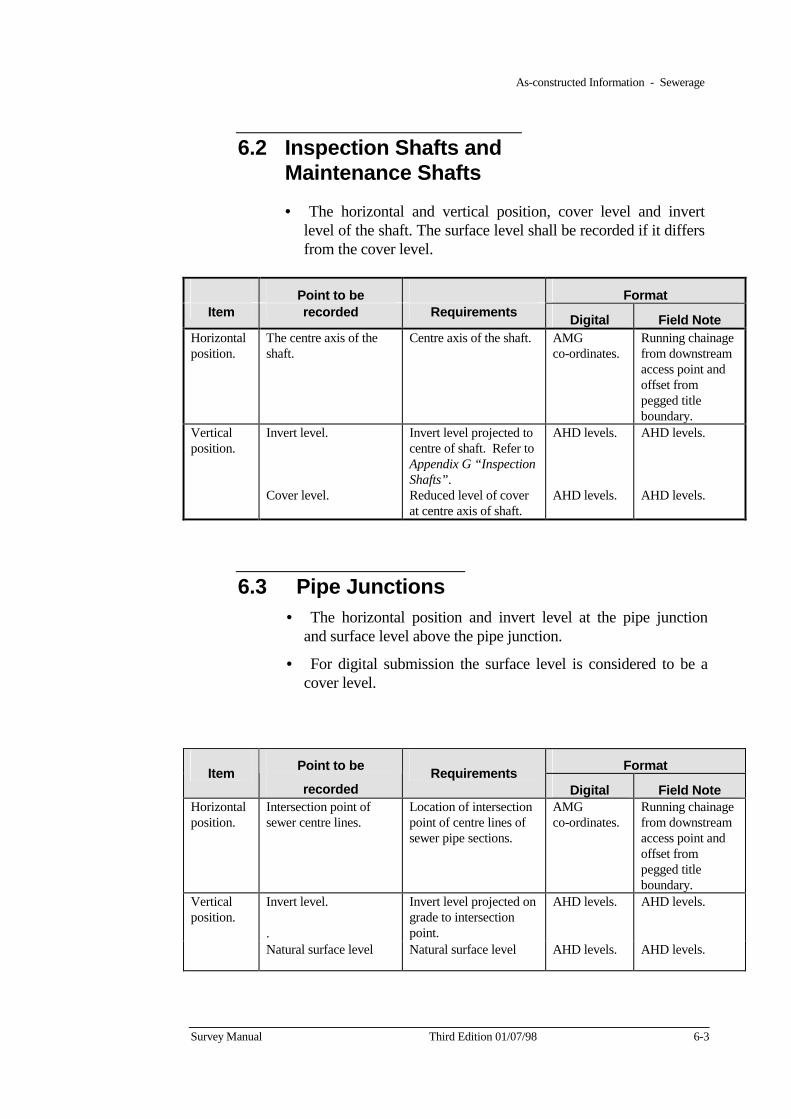
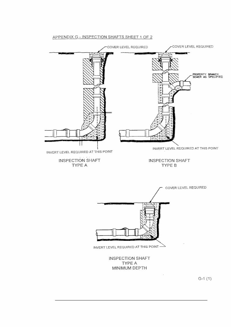
6.2 Inspection Shafts and Maintenance Shafts
• The horizontal and vertical position, cover level and invert level of the shaft. The surface level shall be recorded if it differs from the cover level.
Point to be Format Item recorded Requirements Digital Field Note
Horizontal position.
The centre axis of the shaft.
Centre axis of the shaft. AMG co-ordinates.
Running chainage from downstream access point and offset from pegged title boundary.
Vertical position.
Invert level. Invert level projected to centre of shaft. Refer to Appendix G “Inspection Shafts”.
AHD levels. AHD levels.
Cover level. Reduced level of cover at centre axis of shaft.
AHD levels. AHD levels.
6.3 Pipe Junctions • The horizontal position and invert level at the pipe junction
and surface level above the pipe junction.
• For digital submission the surface level is considered to be a cover level.
Format Item Point to be
recorded Requirements
Digital Field Note Horizontal position.
Intersection point of sewer centre lines.
Location of intersection point of centre lines of sewer pipe sections.
AMG co-ordinates.
Running chainage from downstream access point and offset from pegged title boundary.
Invert level.
.
Invert level projected on grade to intersection point.
AHD levels. AHD levels. Vertical position.
Natural surface level Natural surface level AHD levels. AHD levels.
6-4 Third Edition 01/07/98 Survey Manual
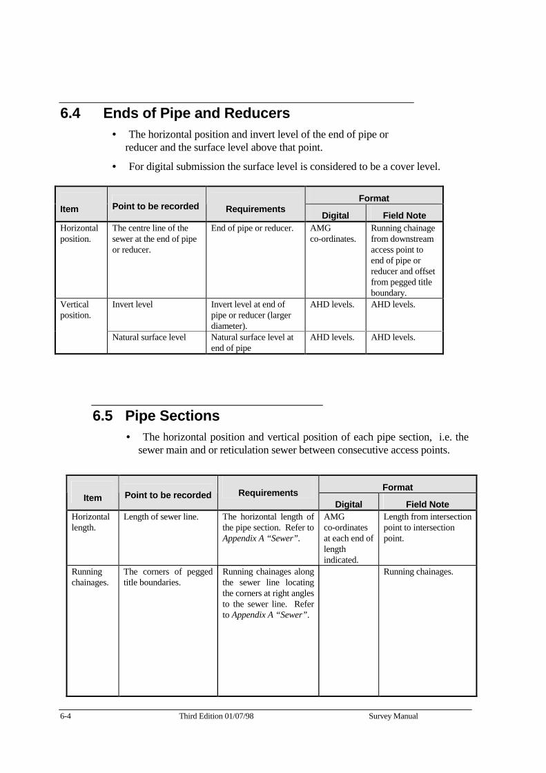
6.4 Ends of Pipe and Reducers • The horizontal position and invert level of the end of pipe or
reducer and the surface level above that point.
• For digital submission the surface level is considered to be a cover level.
Format Item Point to be recorded Requirements Digital Field Note Horizontal position.
The centre line of the sewer at the end of pipe or reducer.
End of pipe or reducer. AMG co-ordinates.
Running chainage from downstream access point to end of pipe or reducer and offset from pegged title boundary.
Invert level
Invert level at end of pipe or reducer (larger diameter).
AHD levels. AHD levels. Vertical position.
Natural surface level Natural surface level at end of pipe
AHD levels. AHD levels.
6.5 Pipe Sections • The horizontal position and vertical position of each pipe section, i.e. the
sewer main and or reticulation sewer between consecutive access points.
Format Item Point to be recorded Requirements
Digital Field Note Horizontal length.
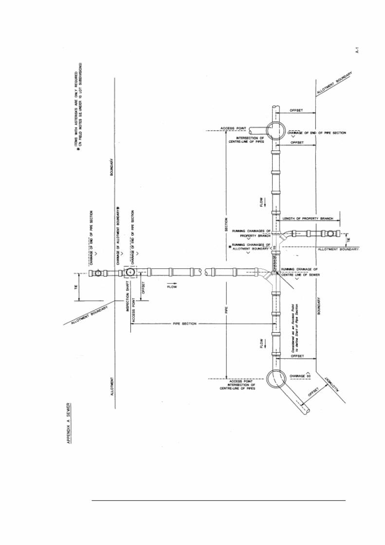
Length of sewer line. The horizontal length of the pipe section. Refer to Appendix A “Sewer”.
AMG co-ordinates at each end of length indicated.
Length from intersection point to intersection point.
Running chainages.
The corners of pegged title boundaries.
Running chainages along the sewer line locating the corners at right angles to the sewer line. Refer to Appendix A “Sewer”.
Running chainages.
As-constructed Information - Sewerage
Survey Manual Third Edition 01/07/98 6-5
Point to be Format Item recorded Requirements
Digital Field Note Horizontal position.
Downstream and upstream ends of the pipe and at changes in direction.
Horizontal position of the centre of the pipe at access points and tangent points. Refer to Appendix A “Sewer”.
AMG co-ordinates offsets indicated.
Distance along and offset from the pegged title boundary.
Vertical position.
Invert level. Refer to “Invert levels” at pages 6-2, 6-3, 6-4, 6-6 & 6-7.
AHD levels. AHD levels.
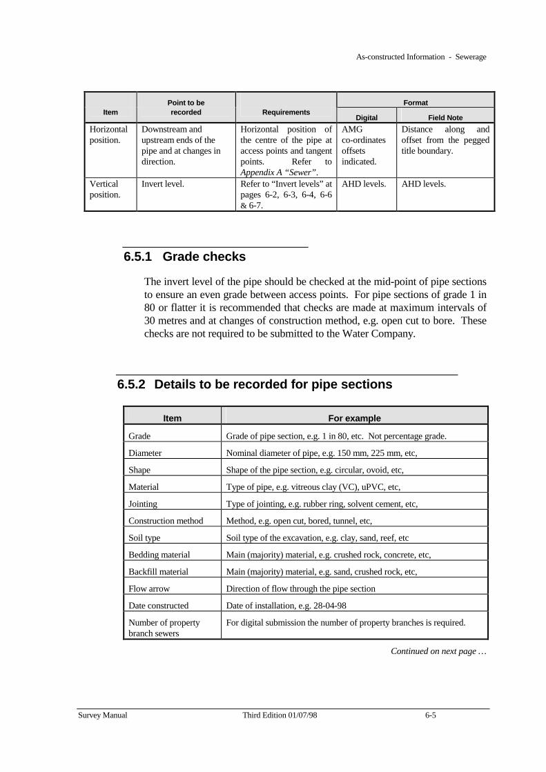
6.5.1 Grade checks
The invert level of the pipe should be checked at the mid-point of pipe sections to ensure an even grade between access points. For pipe sections of grade 1 in 80 or flatter it is recommended that checks are made at maximum intervals of 30 metres and at changes of construction method, e.g. open cut to bore. These checks are not required to be submitted to the Water Company.
6.5.2 Details to be recorded for pipe sections
Item For example
Grade Grade of pipe section, e.g. 1 in 80, etc. Not percentage grade.
Diameter Nominal diameter of pipe, e.g. 150 mm, 225 mm, etc,
Shape Shape of the pipe section, e.g. circular, ovoid, etc,
Material Type of pipe, e.g. vitreous clay (VC), uPVC, etc,
Jointing Type of jointing, e.g. rubber ring, solvent cement, etc,
Construction method Method, e.g. open cut, bored, tunnel, etc,
Soil type Soil type of the excavation, e.g. clay, sand, reef, etc
Bedding material Main (majority) material, e.g. crushed rock, concrete, etc,
Backfill material Main (majority) material, e.g. sand, crushed rock, etc,
Flow arrow Direction of flow through the pipe section
Date constructed Date of installation, e.g. 28-04-98
Number of property branch sewers
For digital submission the number of property branches is required.
Continued on next page …
6-6 Third Edition 01/07/98 Survey Manual
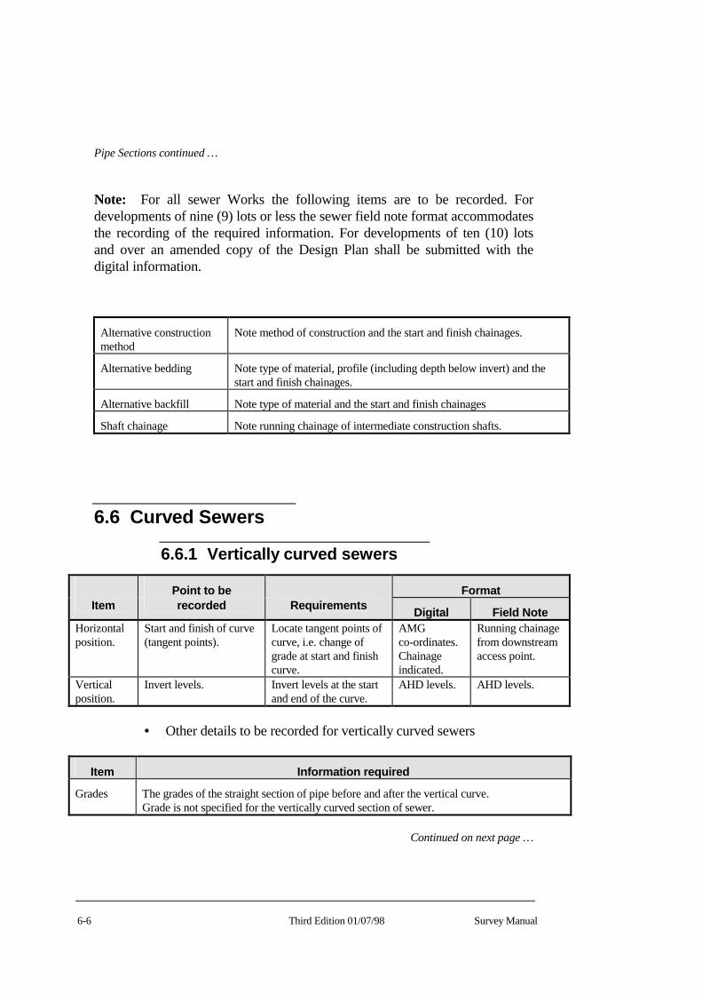
Pipe Sections continued …
Note: For all sewer Works the following items are to be recorded. For developments of nine (9) lots or less the sewer field note format accommodates the recording of the required information. For developments of ten (10) lots and over an amended copy of the Design Plan shall be submitted with the digital information.
Alternative construction method
Note method of construction and the start and finish chainages.
Alternative bedding Note type of material, profile (including depth below invert) and the start and finish chainages.
Alternative backfill Note type of material and the start and finish chainages
Shaft chainage Note running chainage of intermediate construction shafts.
6.6 Curved Sewers
6.6.1 Vertically curved sewers
Point to be Format Item recorded Requirements Digital Field Note
Horizontal position.
Start and finish of curve (tangent points).
Locate tangent points of curve, i.e. change of grade at start and finish curve.
AMG co-ordinates. Chainage indicated.
Running chainage from downstream access point.
Vertical position.
Invert levels. Invert levels at the start and end of the curve.
AHD levels. AHD levels.
• Other details to be recorded for vertically curved sewers
Item Information required
Grades The grades of the straight section of pipe before and after the vertical curve. Grade is not specified for the vertically curved section of sewer.
Continued on next page …
As-constructed Information - Sewerage
Survey Manual Third Edition 01/07/98 6-7
Curved Sewers continued …
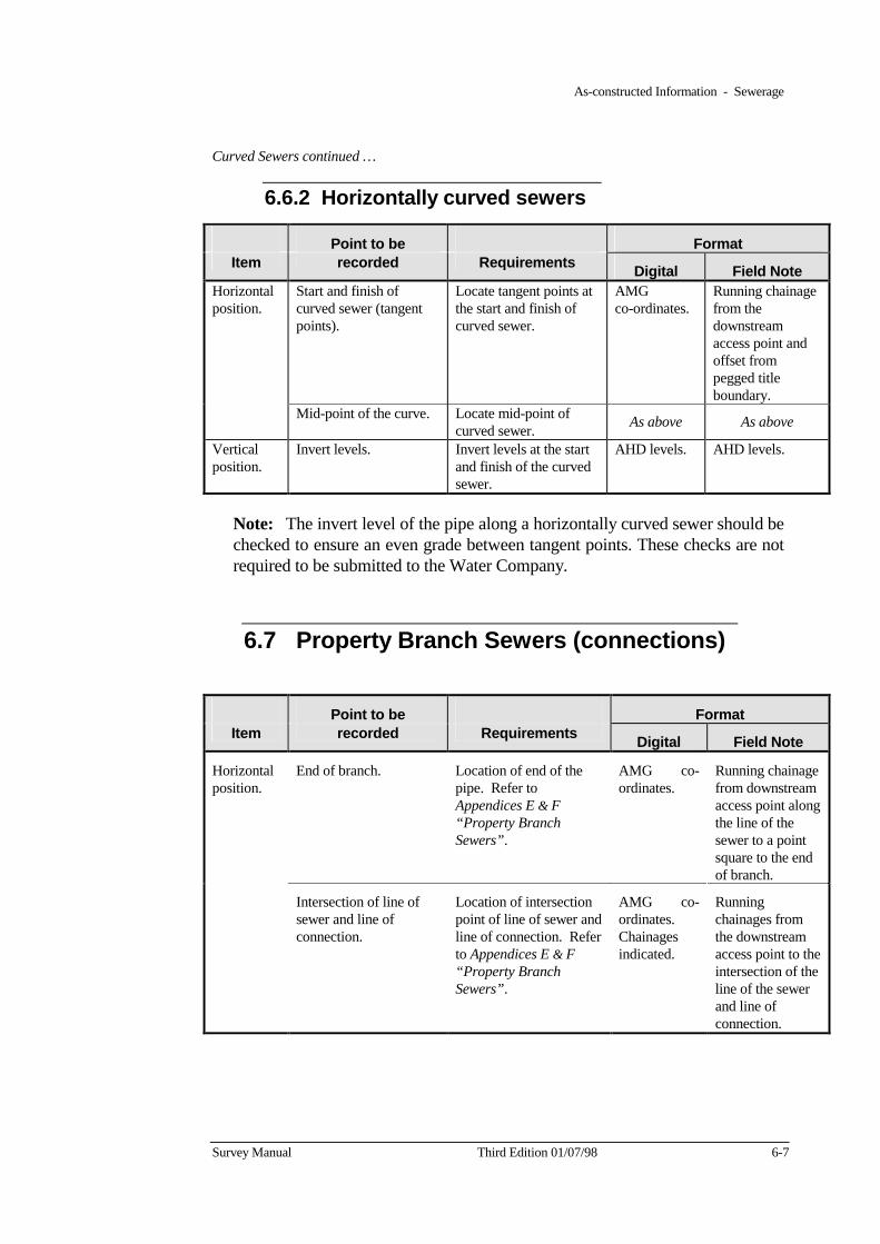
6.6.2 Horizontally curved sewers
Point to be Format Item recorded Requirements Digital Field Note
Start and finish of curved sewer (tangent points).
Locate tangent points at the start and finish of curved sewer.
AMG co-ordinates.
Running chainage from the downstream access point and offset from pegged title boundary.
Horizontal position.
Mid-point of the curve. Locate mid-point of curved sewer. As above As above
Vertical position.
Invert levels. Invert levels at the start and finish of the curved sewer.
AHD levels. AHD levels.
Note: The invert level of the pipe along a horizontally curved sewer should be checked to ensure an even grade between tangent points. These checks are not required to be submitted to the Water Company.
6.7 Property Branch Sewers (connections)
Point to be Format Item recorded Requirements Digital Field Note
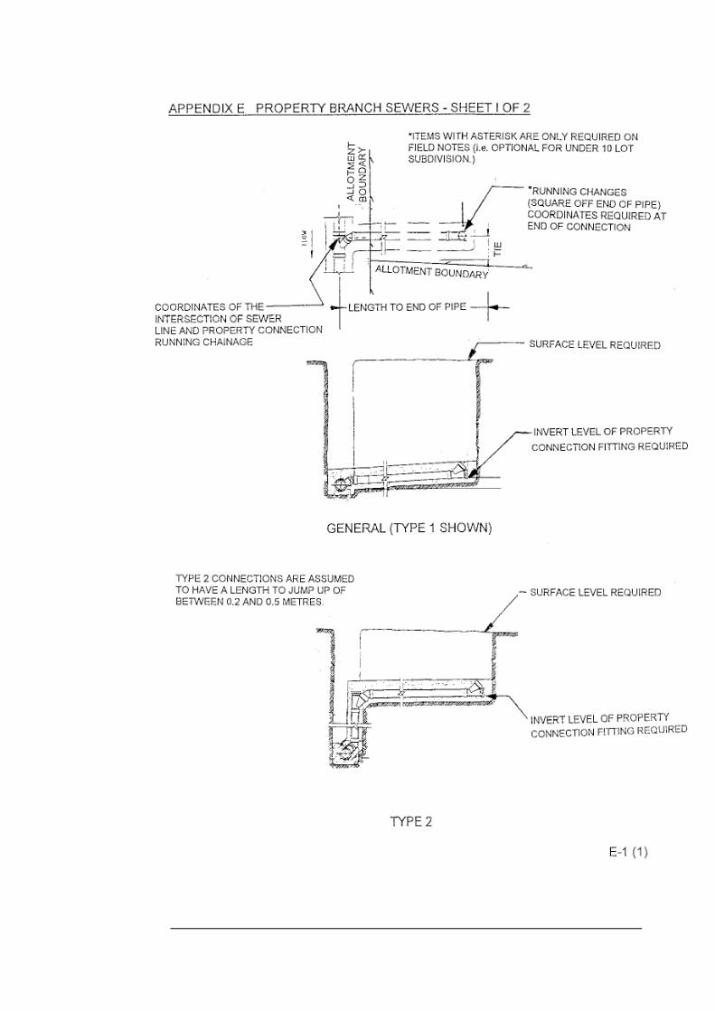
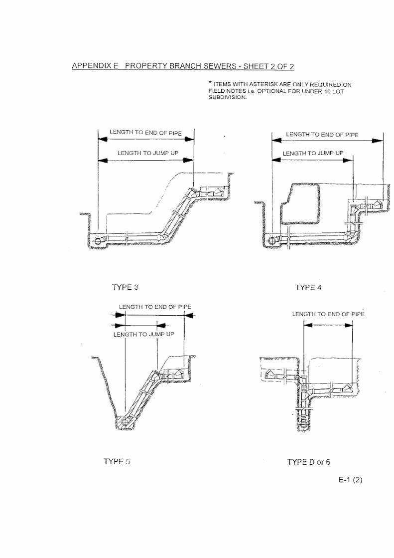
End of branch. Location of end of the pipe. Refer to Appendices E & F “Property Branch Sewers”.
AMG co-ordinates.
Running chainage from downstream access point along the line of the sewer to a point square to the end of branch.
Horizontal position.
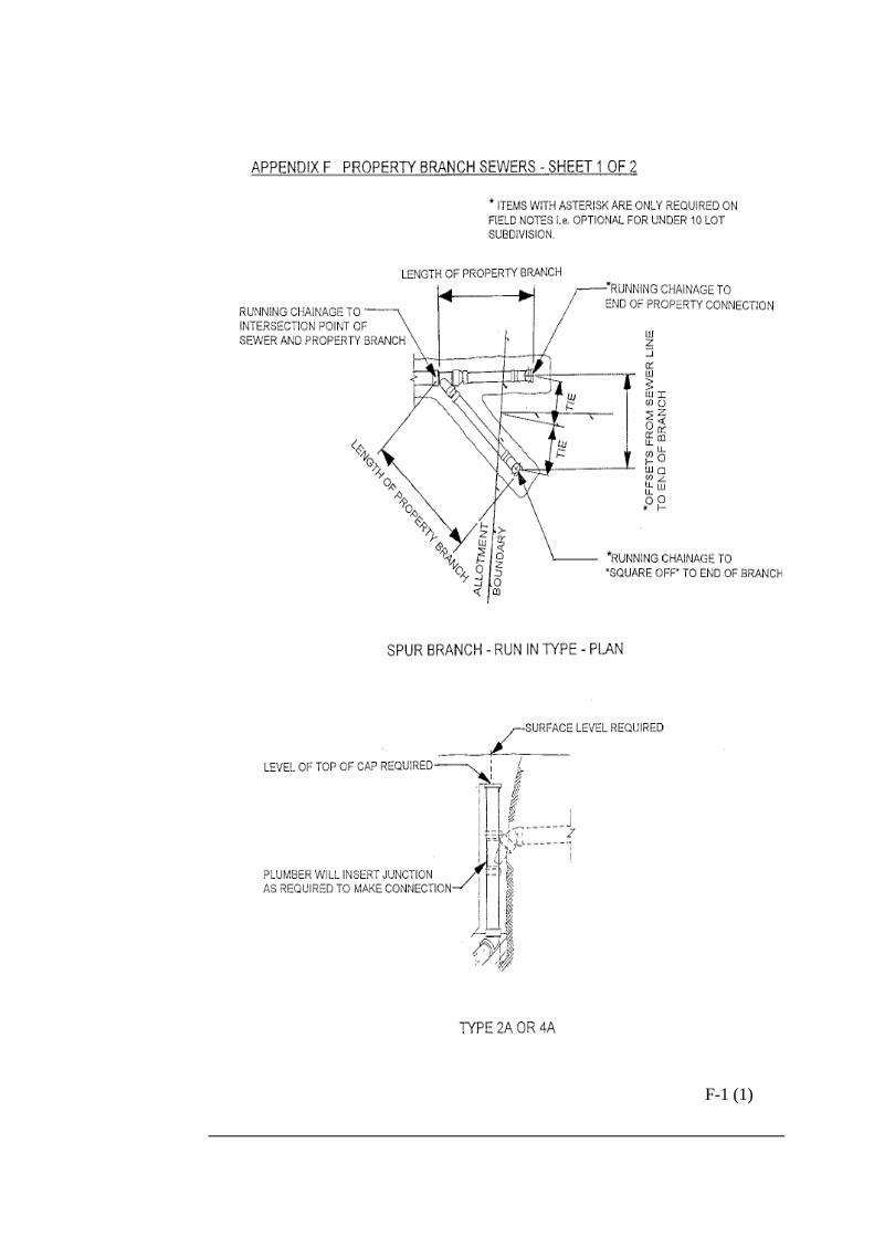
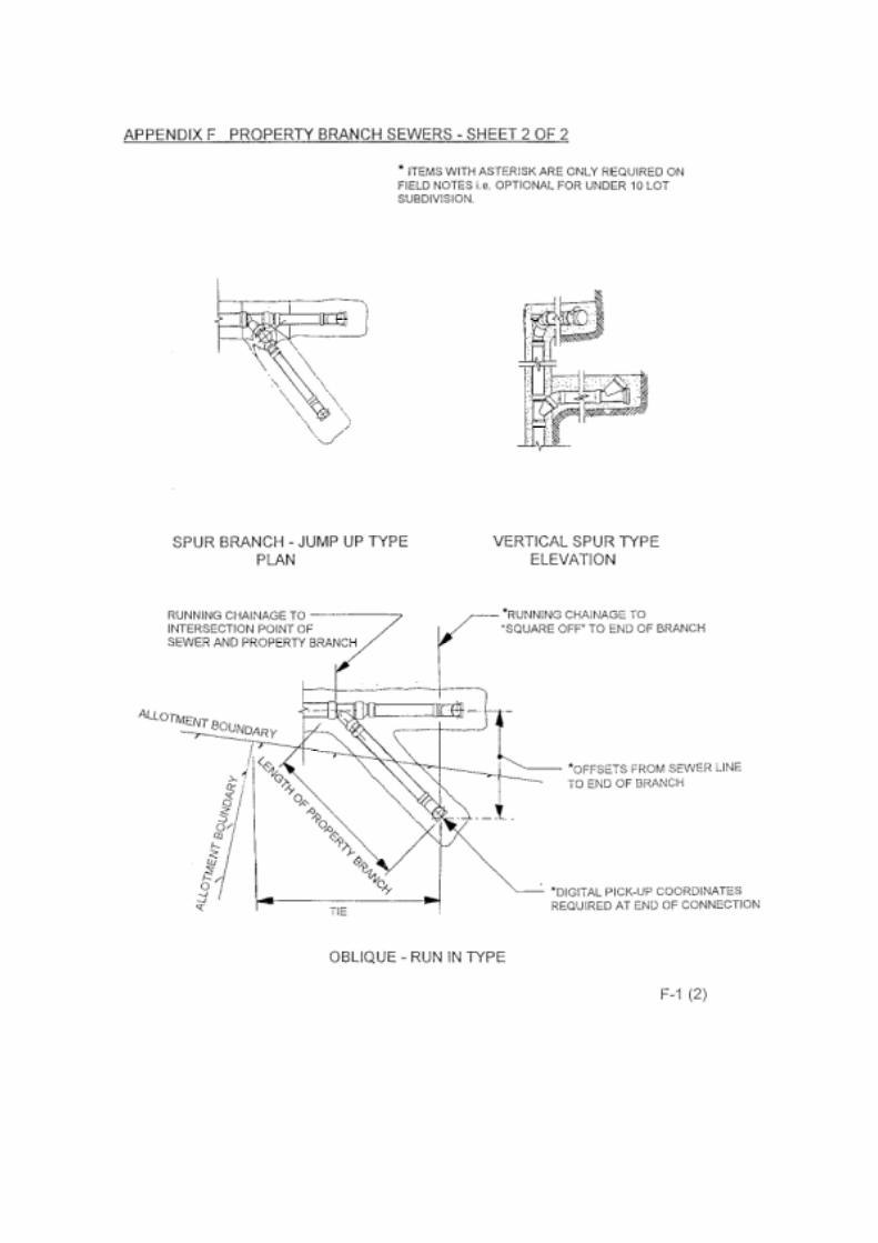
Intersection of line of sewer and line of connection.
Location of intersection point of line of sewer and line of connection. Refer to Appendices E & F “Property Branch Sewers”.
AMG co-ordinates. Chainages indicated.
Running chainages from the downstream access point to the intersection of the line of the sewer and line of connection.

6-8 Third Edition 01/07/98 Survey Manual
Point to be Format
Item recorded Requirements Digital Field Note
Length of branch. Distance along the branch from the intersection of sewer line and the property branch to the end of branch. Refer to Appendices E & F “Property Branch Sewers” and page 4-5 (Example sewer field note).
AMG co-ordinates.
Distance along the branch.
Horizontal distance.
Distance along branch to jump up.
Distance along the branch from the intersection of the sewer line and the property branch to the jump up. Refer to Appendices E & F “Property Branch Sewers” and page 4-5 (Example sewer field note).
AMG co-ordinates. Distance indicated if more than 1.00m.
Distance along the branch to jump up.
Distance from the nearest title corner of the property serviced to the end of the branch. The distance is parallel to the title boundary.
Tie distance indicated.
Tie distance. Tie distance.
End of branch.
Alternatively two (2) ties can be used from title corners directly to end of branch (for unusual situations such as curved boundary). Refer to Appendices E & F “Property Branch Sewers”.
Direct ties. Direct ties.
Horizontal position.
Oblique branch (Ob) constructed for future connection.
Location of oblique branch.
AMG co-ordinates of point of entry. Chainage indicated.
Running chainage from downstream access point along the line of the sewer to the point of entry.
Connections continued …
Survey Manual Third Edition 01/07/98 6-9
Point to be Format
Item recorded Requirements Digital Field Note
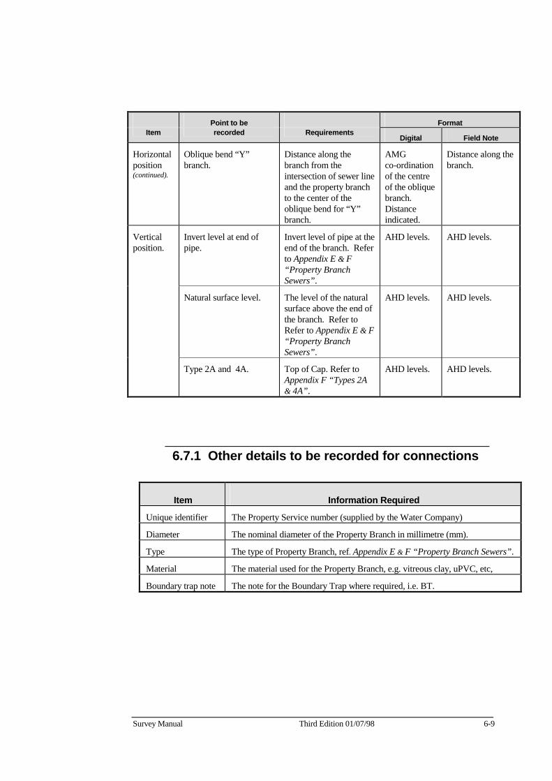
Horizontal position (continued).
Oblique bend “Y” branch.
Distance along the branch from the intersection of sewer line and the property branch to the center of the oblique bend for “Y” branch.
AMG co-ordination of the centre of the oblique branch. Distance indicated.
Distance along the branch.
Invert level at end of pipe.
Invert level of pipe at the end of the branch. Refer to Appendix E & F “Property Branch Sewers”.
AHD levels. AHD levels.
Natural surface level. The level of the natural surface above the end of the branch. Refer to Refer to Appendix E & F “Property Branch Sewers”.
AHD levels. AHD levels.
Vertical position.
Type 2A and 4A. Top of Cap. Refer to Appendix F “Types 2A & 4A”.
AHD levels. AHD levels.
6.7.1 Other details to be recorded for connections
Item Information Required
Unique identifier The Property Service number (supplied by the Water Company)
Diameter The nominal diameter of the Property Branch in millimetre (mm).
Type The type of Property Branch, ref. Appendix E & F “Property Branch Sewers”.
Material The material used for the Property Branch, e.g. vitreous clay, uPVC, etc,
Boundary trap note The note for the Boundary Trap where required, i.e. BT.
6-10 Third Edition 01/07/98 Survey Manual
6.8 Other sewerage details to be recorded In addition to the horizontal and vertical position, the following details shall also be recorded:
• Job identification (obtained from the Water Company).
• Municipality.
• Field book and page number (obtained from the Water Company) for information supplied in sewer field note format.

Survey Manual Third Edition 01/07/98 7-1
Chapter 7 Pumping Stations and Rising Mains
7 General The Surveyor shall be responsible for the recording of as-constructed information detailing sewerage pumping stations and rising mains and the forwarding of the as-constructed information to the Consultant.
Position shall be recorded relative to the Australian Map Grid and the Australian Height Datum when the Design Plans specify AMG co-ordinates and AHD levels.
The as-constructed information shall be supplied in either .DXF or MicroStation .DGN digital format and shall be accompanied by an amended copy of the Design Plan showing as-constructed details.
7.1 Pumping stations Refer to Sewerage Digital Input Manual for items to be recorded.
7.2 Rising mains Refer to Sewerage Digital Input Manual for items to be recorded.
Vertical position shall be recorded at:
• Vertical bends
• Changes of grade
• Start and finish of rising main (at Pumping Station and
outlet access point)
Vertical position may be recorded as depth from surface to top of pipe when Design Plans do not specify AHD levels.
Continued on next page …

7-2 Third Edition 01/07/98 Survey Manual
Rising Mains continued …
Horizontal (plan) position shall be recorded at:
• Horizontal bends (change in direction)
• Changes of grade
• Fittings
• Changes in pipe characteristics, e.g. material, diameter, etc,
• Changes in construction method
Horizontal (plan) position may be recorded relative to pegged title boundaries and running chainage when Design Plans do not specify AMG co-ordinates.

Part 4 Appendices

F-1 (1)


Issue No 5, July 1998 1 of 2
Verification Form Acceptance of Non-digital As-constructed Information for Water Supply Works
Job description : ___________________________________ Municipality : ___________________________________ Consultant : ___________________________________ Nominated Rep. : ___________________________________ Consultant Ref. No. : ___________________________________ Water Company Ref. : ___________________________________
Documentation to be submitted
1. Evidence of third party verification to ISO 9001 quality system standard or evidence of accreditation acceptable to the Water Company.
2. A hardcopy of the asset information.
3. All information supplied is labelled with the Supplier’s name and the Water Company reference number for the Works.
4. The name of the Survey Company used to supply the information.
5. Verification Form Attachment Sheet, if any of the items on this form are not applicable.

Acceptance of Survey Verification Forms Non-digital As-constructed Information for Water Supply Works
2 of 2 Issue No 5, May 1998
Consultant's Verification
As the Consultant's nominated representative responsible for the Works detailed in Water Company Reference No. _________/_________/_____________,
I certify that:
• the survey is in accordance with the Offer,
• the survey has been completed in accordance with our company’s quality system,
• the survey is in accordance with the Water Company Survey Manual,
• the survey is in accordance with all relevant Water Company specifications and relevant Australian Standards,
• the source documents have been filed in a manner that can be readily accessed for audit purposes.
Nominated Representative __________________________________
________________________________
Name Company Position __________________________________ ________________________________
Signature Date

Issue No 5, July 1998 1 of 2
Verification Form Acceptance of Digital As-constructed Information for Sewerage Works
Job description : ___________________________________ Municipality : ___________________________________ Consultant : ___________________________________ Nominated Rep. : ___________________________________ Consultant Ref. No. : ___________________________________ Water Company Ref. : ___________________________________
Documentation to be submitted
1. Evidence of third party verification to ISO 9001 quality system standard or evidence of accreditation acceptable to the Water Company.
2. A hardcopy of the asset information.
3. All information supplied is labelled with the Supplier’s name and the Water Company reference number for the Works.
4. Specific identification of file is required, i.e. .DGN, .DXF, linked or unlinked in accordance with the Sewerage Digital Input Manual.
5. The name of the Survey Company used to supply the information.
6. Verification Form Attachment Sheet, if any of the items on this form are not applicable.

Acceptance of Survey Verification Forms Digital As-constructed Information for Sewerage Works
2 of 2 Issue No 5, May 1998
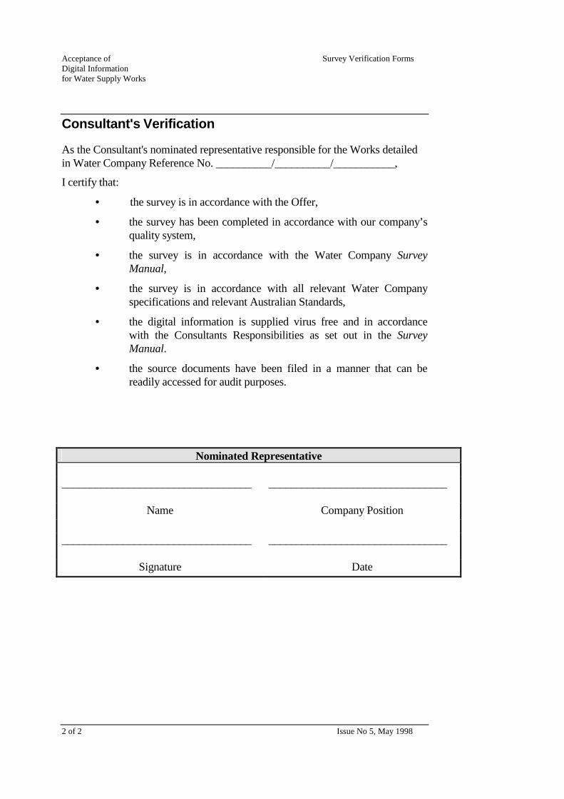
Consultant's Verification
As the Consultant's nominated representative responsible for the Works detailed in Water Company Reference No. __________/__________/___________,
I certify that:
• the survey is in accordance with the Offer,
• the survey has been completed in accordance with our company’s quality system,
• the survey is in accordance with the Water Company Survey Manual,
• the survey is in accordance with all relevant Water Company specifications and relevant Australian Standards,
• the digital information is supplied virus free and in accordance with the Consultants Responsibilities as set out in the Survey Manual,
• the source documents have been filed in a manner that can be readily accessed for audit purposes.
Nominated Representative __________________________________
________________________________
Name Company Position __________________________________ ________________________________
Signature Date

Issue No 4, July 1998 1 of 2
Verification Form Acceptance of Digital As-constructed Information for Water Supply Works
Job description : ___________________________________ Municipality : ___________________________________ Consultant : ___________________________________ Nominated Rep. : ___________________________________ Consultant Ref. No. : ___________________________________ Water Company Ref. : ___________________________________
Documentation to be submitted
1. Evidence of third party verification to ISO 9001 quality system standard or evidence of accreditation that is acceptable to the Water Company.
2. A hardcopy of the asset information.
3. All information supplied is labelled with the Supplier’s name and the Water Company reference number for the Works.
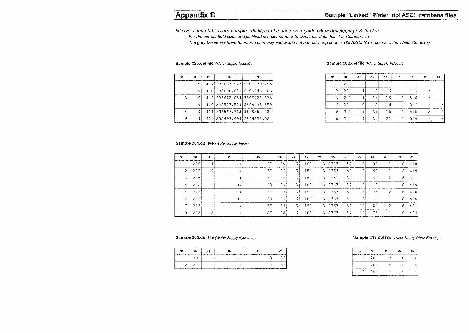
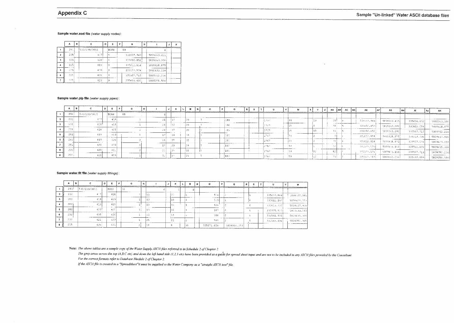
4. Specific identification of file is required, i.e. .DGN, .DXF, linked or unlinked in accordance with the Water Supply Digital Input Manual.
5. The name of the Survey Company used to supply the information.
6. Verification Form Attachment Sheet, if any of the items on this form are not applicable.
Acceptance of Survey Verification Forms Digital Information for Water Supply Works
2 of 2 Issue No 5, May 1998
Consultant's Verification
As the Consultant's nominated representative responsible for the Works detailed in Water Company Reference No. __________/__________/___________,
I certify that:
• the survey is in accordance with the Offer,
• the survey has been completed in accordance with our company’s quality system,
• the survey is in accordance with the Water Company Survey Manual,
• the survey is in accordance with all relevant Water Company specifications and relevant Australian Standards,
• the digital information is supplied virus free and in accordance with the Consultants Responsibilities as set out in the Survey Manual.
• the source documents have been filed in a manner that can be readily accessed for audit purposes.
Nominated Representative __________________________________
________________________________
Name Company Position __________________________________ ________________________________
Signature Date

Issue No 5, July 1998 1 of 2
Verification Form Acceptance of Digital Subdivision Information Job description : ___________________________________ Municipality : ___________________________________ Consultant : ___________________________________ Nominated Rep. : ___________________________________ Consultant Ref. No. : ___________________________________ Water Company Ref. : ___________________________________
Documentation to be submitted
1. Evidence of third party verification to ISO 9001 quality system standard or evidence of accreditation acceptable to the Water Company.
2. A hardcopy of the Plan of Subdivision.
3. All information supplied is labelled with the Supplier’s name and the Titles Office Plan of Subdivision number.
4. A .DGN level or .DXF layer specifications form.
5. The name of the Survey Company used to supply the information.
6. Verification Form Attachment Sheet, if any of the items on this form are not applicable
Acceptance of Survey Verification Forms Digital Subdivision Information
2 of 2 Issue No 5, May 1998
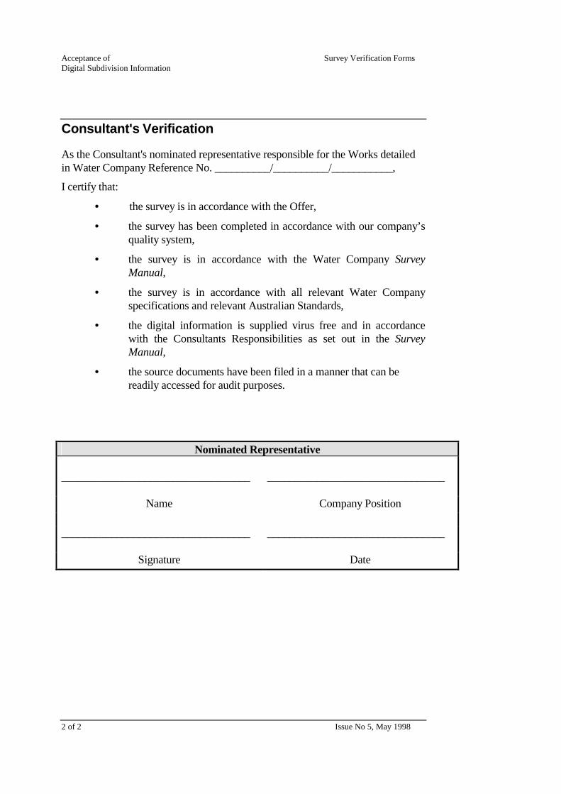
Consultant's Verification
As the Consultant's nominated representative responsible for the Works detailed in Water Company Reference No. __________/__________/___________,
I certify that:
• the survey is in accordance with the Offer,
• the survey has been completed in accordance with our company’s quality system,
• the survey is in accordance with the Water Company Survey Manual,
• the survey is in accordance with all relevant Water Company specifications and relevant Australian Standards,
• the digital information is supplied virus free and in accordance with the Consultants Responsibilities as set out in the Survey Manual,
• the source documents have been filed in a manner that can be readily accessed for audit purposes.
Nominated Representative __________________________________
________________________________
Name Company Position __________________________________ ________________________________
Signature Date

Issue No 5, July 1998 1 of 2
Verification Form Acceptance of Non-digital As-constructed Information for Sewerage Works
Job description : ___________________________________ Municipality : ___________________________________ Consultant : ___________________________________ Nominated Rep. : ___________________________________ Consultant Ref. No. : ___________________________________ Water Company Ref. : ___________________________________
Documentation to be submitted
1. Evidence of third party verification to ISO 9001 quality system standard or evidence of accreditation acceptable to the Water Company.
2. A hardcopy of the asset information.
3. All information supplied is labelled with the Supplier’s name and the Water Company reference number for the Works.
4. The name of the Survey Company used to supply the information.
5. Verification Form Attachment Sheet, if any of the items on this form are not applicable.

Acceptance of Survey Verification Forms Non-digital As-constructed Information for Sewerage Works
2 of 2 Issue No 5, February 1998
Consultant's Verification
As the Consultant's nominated representative responsible for the Works detailed in Water Company Reference No. __________/__________/___________,
I certify that:
• the survey is in accordance with the Offer,
• the survey has been completed in accordance with our company’s quality system,
• the survey is in accordance with the Water Company Survey Manual,
• the survey is in accordance with all relevant Water Company specifications and relevant Australian Standards,
• the source documents have been filed in a manner that can be readily accessed for audit purposes.
Nominated Representative __________________________________
________________________________
Name Company Position __________________________________ ________________________________
Signature Date

Issue No 5, July 1998 1 of 2
Verification Form Acceptance of
Non-digital Subdivision Information Job description : ___________________________________ Municipality : ___________________________________ Consultant : ___________________________________ Nominated Rep. : ___________________________________ Consultant Ref. No. : ___________________________________ Water Company Ref. : ___________________________________
Documentation to be submitted
1. Evidence of third party verification to ISO 9001 quality system standard or evidence of accreditation acceptable to the Water Company.
2. A hardcopy of the Plan of Subdivision.
3. All information supplied is labelled with the Supplier’s name and the Titles Office Plan of Subdivision number.
4. The name of the Survey Company used to supply the information.
5. Verification Form Attachment Sheet, if any of the items on this form are not applicable
Acceptance of Survey Verification Forms Non-digital Subdivision Information
2 of 2 Issue No 5, May 1998
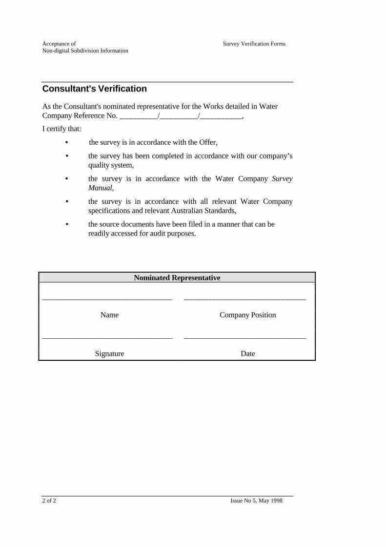
Consultant's Verification
As the Consultant's nominated representative for the Works detailed in Water Company Reference No. __________/__________/___________,
I certify that:
• the survey is in accordance with the Offer,
• the survey has been completed in accordance with our company’s quality system,
• the survey is in accordance with the Water Company Survey Manual,
• the survey is in accordance with all relevant Water Company specifications and relevant Australian Standards,
• the source documents have been filed in a manner that can be readily accessed for audit purposes.
Nominated Representative __________________________________
________________________________
Name Company Position __________________________________ ________________________________
Signature Date

Survey Verification Forms
Third Edition No

Copyright Yarra Valley Water Ltd. © 1998 Copyright South East Water Ltd. © 1998 Copyright City West Water Ltd. © 1998 All rights reserved. This publication is protected by copyright and is provided under licence. Permission is granted for registered users to copy the Survey Verification Forms for dealings with the three Water Companies. No other Part of this publication may be reproduced, distributed, transmitted, stored in a retrieval system or reduced to any electronic medium. The Water Companies assume no responsibility for any errors that may appear in this document or any damages arising out of the use or inability to use this document. Changes may be made periodically to the information herein. May 1998

Survey Verification Forms 17/07/2002 iii
About the Verification Forms
This Section describes the Survey Verification Forms to be completed at each of the following stages of a project:
• the acceptance of non-digital subdivision information,
• the acceptance of digital subdivision information,
• the acceptance of non-digital as-constructed information for water supply and sewerage Works,
• the acceptance of digital as-constructed information for water supply and sewerage Works.
Separate Verification Forms are required for water supply and sewerage Works.
The total number of pages for each form is shown at the bottom right of each page. Each form also has a Verification Form Attachment Sheet.
Be careful to photocopy and include all pages when completing a Verification Form.
The forms are included in this Section in the following order. Page counts include the Verification Form Attachment Sheet.
No of Pages
Acceptance of Non-digital Subdivision Information 2
Acceptance of Digital Subdivision Information 2
Acceptance of Non-digital As-constructed Information for Water Supply Works 2
Acceptance of Digital As-constructed Information for Water Supply Works 2
Acceptance of Non-digital As-constructed Information for Sewerage Works 2
Acceptance of Digital As-constructed Information for Sewerage Works 2
Verification Form Attachment Sheet 1
Issue No 5, July 1998 Page ___ of ___
Verification Form Attachment Sheet Job description : _____________________________________________ Municipality : _____________________________________________ Consultant : _____________________________________________ Water Company Ref. No. : _____________________________________________ Verification Form : _____________________________________________
Note: Please attach a copy of this sheet to the Verification Form, if needed.
Item No. Comments
Nominated Representative : ____________________________________________
Signature : ____________________________________________
Issue No 5, July 1998 1 of 2
Verification Form Acceptance of Non-digital As-constructed Information for Water Supply Works
Job description : ___________________________________ Municipality : ___________________________________ Consultant : ___________________________________ Nominated Rep. : ___________________________________ Consultant Ref. No. : ___________________________________ Water Company Ref. : ___________________________________
Documentation to be submitted
1. Evidence of third party verification to ISO 9001 quality system standard or evidence of accreditation acceptable to the Water Company.
2. A hardcopy of the asset information.
3. All information supplied is labelled with the Supplier’s name and the Water Company reference number for the Works.
4. The name of the Survey Company used to supply the information.
5. Verification Form Attachment Sheet, if any of the items on this form are not applicable.

Acceptance of Survey Verification Forms Non-digital As-constructed Information for Water Supply Works
2 of 2 Issue No 5, May 1998
Consultant's Verification
As the Consultant's nominated representative responsible for the Works detailed in Water Company Reference No. _________/_________/_____________,
I certify that:
• the survey is in accordance with the Offer,
• the survey has been completed in accordance with our company’s quality system,
• the survey is in accordance with the Water Company Survey Manual,
• the survey is in accordance with all relevant Water Company specifications and relevant Australian Standards,
• the source documents have been filed in a manner that can be readily accessed for audit purposes.
Nominated Representative __________________________________
________________________________
Name Company Position __________________________________ ________________________________
Signature Date

Issue No 5, July 1998 1 of 2
Verification Form Acceptance of Digital As-constructed Information for Sewerage Works
Job description : ___________________________________ Municipality : ___________________________________ Consultant : ___________________________________ Nominated Rep. : ___________________________________ Consultant Ref. No. : ___________________________________ Water Company Ref. : ___________________________________
Documentation to be submitted
1. Evidence of third party verification to ISO 9001 quality system standard or evidence of accreditation acceptable to the Water Company.
2. A hardcopy of the asset information.
3. All information supplied is labelled with the Supplier’s name and the Water Company reference number for the Works.
4. Specific identification of file is required, i.e. .DGN, .DXF, linked or unlinked in accordance with the Sewerage Digital Input Manual.
5. The name of the Survey Company used to supply the information.
6. Verification Form Attachment Sheet, if any of the items on this form are not applicable.
Acceptance of Survey Verification Forms Digital As-constructed Information for Sewerage Works
2 of 2 Issue No 5, May 1998
Consultant's Verification
As the Consultant's nominated representative responsible for the Works detailed in Water Company Reference No. __________/__________/___________,
I certify that:
• the survey is in accordance with the Offer,
• the survey has been completed in accordance with our company’s quality system,
• the survey is in accordance with the Water Company Survey Manual,
• the survey is in accordance with all relevant Water Company specifications and relevant Australian Standards,
• the digital information is supplied virus free and in accordance with the Consultants Responsibilities as set out in the Survey Manual,
• the source documents have been filed in a manner that can be readily accessed for audit purposes.
Nominated Representative __________________________________
________________________________
Name Company Position __________________________________ ________________________________
Signature Date

Issue No 4, July 1998 1 of 2
Verification Form Acceptance of Digital As-constructed Information for Water Supply Works
Job description : ___________________________________ Municipality : ___________________________________ Consultant : ___________________________________ Nominated Rep. : ___________________________________ Consultant Ref. No. : ___________________________________ Water Company Ref. : ___________________________________
Documentation to be submitted
1. Evidence of third party verification to ISO 9001 quality system standard or evidence of accreditation that is acceptable to the Water Company.
2. A hardcopy of the asset information.
3. All information supplied is labelled with the Supplier’s name and the Water Company reference number for the Works.
4. Specific identification of file is required, i.e. .DGN, .DXF, linked or unlinked in accordance with the Water Supply Digital Input Manual.
5. The name of the Survey Company used to supply the information.
6. Verification Form Attachment Sheet, if any of the items on this form are not applicable.

Acceptance of Survey Verification Forms Digital Information for Water Supply Works
2 of 2 Issue No 5, May 1998
Consultant's Verification
As the Consultant's nominated representative responsible for the Works detailed in Water Company Reference No. __________/__________/___________,
I certify that:
• the survey is in accordance with the Offer,
• the survey has been completed in accordance with our company’s quality system,
• the survey is in accordance with the Water Company Survey Manual,
• the survey is in accordance with all relevant Water Company specifications and relevant Australian Standards,
• the digital information is supplied virus free and in accordance with the Consultants Responsibilities as set out in the Survey Manual.
• the source documents have been filed in a manner that can be readily accessed for audit purposes.
Nominated Representative __________________________________
________________________________
Name Company Position __________________________________ ________________________________
Signature Date

Issue No 5, July 1998 1 of 2
Verification Form Acceptance of Digital Subdivision Information Job description : ___________________________________ Municipality : ___________________________________ Consultant : ___________________________________ Nominated Rep. : ___________________________________ Consultant Ref. No. : ___________________________________ Water Company Ref. : ___________________________________
Documentation to be submitted
1. Evidence of third party verification to ISO 9001 quality system standard or evidence of accreditation acceptable to the Water Company.
2. A hardcopy of the Plan of Subdivision.
3. All information supplied is labelled with the Supplier’s name and the Titles Office Plan of Subdivision number.
4. A .DGN level or .DXF layer specifications form.
5. The name of the Survey Company used to supply the information.
6. Verification Form Attachment Sheet, if any of the items on this form are not applicable

Acceptance of Survey Verification Forms Digital Subdivision Information
2 of 2 Issue No 5, May 1998
Consultant's Verification
As the Consultant's nominated representative responsible for the Works detailed in Water Company Reference No. __________/__________/___________,
I certify that:
• the survey is in accordance with the Offer,
• the survey has been completed in accordance with our company’s quality system,
• the survey is in accordance with the Water Company Survey Manual,
• the survey is in accordance with all relevant Water Company specifications and relevant Australian Standards,
• the digital information is supplied virus free and in accordance with the Consultants Responsibilities as set out in the Survey Manual,
• the source documents have been filed in a manner that can be readily accessed for audit purposes.
Nominated Representative __________________________________
________________________________
Name Company Position __________________________________ ________________________________
Signature Date

Issue No 5, July 1998 1 of 2
Verification Form Acceptance of Non-digital As-constructed Information for Sewerage Works
Job description : ___________________________________ Municipality : ___________________________________ Consultant : ___________________________________ Nominated Rep. : ___________________________________ Consultant Ref. No. : ___________________________________ Water Company Ref. : ___________________________________
Documentation to be submitted
1. Evidence of third party verification to ISO 9001 quality system standard or evidence of accreditation acceptable to the Water Company.
2. A hardcopy of the asset information.
3. All information supplied is labelled with the Supplier’s name and the Water Company reference number for the Works.
4. The name of the Survey Company used to supply the information.
5. Verification Form Attachment Sheet, if any of the items on this form are not applicable.

Acceptance of Survey Verification Forms Non-digital As-constructed Information for Sewerage Works
2 of 2 Issue No 5, February 1998
Consultant's Verification
As the Consultant's nominated representative responsible for the Works detailed in Water Company Reference No. __________/__________/___________,
I certify that:
• the survey is in accordance with the Offer,
• the survey has been completed in accordance with our company’s quality system,
• the survey is in accordance with the Water Company Survey Manual,
• the survey is in accordance with all relevant Water Company specifications and relevant Australian Standards,
• the source documents have been filed in a manner that can be readily accessed for audit purposes.
Nominated Representative __________________________________
________________________________
Name Company Position __________________________________ ________________________________
Signature Date

Issue No 5, July 1998 1 of 2
Verification Form Acceptance of
Non-digital Subdivision Information Job description : ___________________________________ Municipality : ___________________________________ Consultant : ___________________________________ Nominated Rep. : ___________________________________ Consultant Ref. No. : ___________________________________ Water Company Ref. : ___________________________________
Documentation to be submitted
1. Evidence of third party verification to ISO 9001 quality system standard or evidence of accreditation acceptable to the Water Company.
2. A hardcopy of the Plan of Subdivision.
3. All information supplied is labelled with the Supplier’s name and the Titles Office Plan of Subdivision number.
4. The name of the Survey Company used to supply the information.
5. Verification Form Attachment Sheet, if any of the items on this form are not applicable

Acceptance of Survey Verification Forms Non-digital Subdivision Information
2 of 2 Issue No 5, May 1998
Consultant's Verification
As the Consultant's nominated representative for the Works detailed in Water Company Reference No. __________/__________/___________,
I certify that:
• the survey is in accordance with the Offer,
• the survey has been completed in accordance with our company’s quality system,
• the survey is in accordance with the Water Company Survey Manual,
• the survey is in accordance with all relevant Water Company specifications and relevant Australian Standards,
• the source documents have been filed in a manner that can be readily accessed for audit purposes.
Nominated Representative __________________________________
________________________________
Name Company Position __________________________________ ________________________________
Signature Date

Sewerage Digital Input Manual
Second Edition No.
ii 17/07/2002 Sewerage Digital Input Manual
Copyright Melbourne Water Ltd. 1995 Copyright Yarra Valley Water Ltd. 1995 Copyright South East Water Ltd. 1995 Copyright City West Water Ltd. 1995 All rights reserved. This publication is protected by copyright and is provided under licence. No part of this publication may be reproduced, distributed, transmitted, stored in a retrieval system, or reduced to any electronic medium without the written authority of the Managing Director of the Water Company. The Water Company assumes no responsibility for any errors in or omissions from this document or any damages arising out of the use or inability to use this document. Changes may be made periodically to the information herein. “Intergraph” and “IGDS” are registered trademarks of the Intergraph Corporation. “MicroStation” is a trademark of Bentley Systems Incorporated and an affiliate of Intergraph Corporation. “VAX” is a trademark of Digital Equipment. “UNIX” is a trademark of AT & T Bell Laboratories. “dBASE” is a registered trademark of Ashton-Tate. “PC-DOS” is a registered trademark of International Business Machines Corporation. “INFORMIX” is a registered trademark of Informix Software Incorporated. March 1995
Sewerage Digital Input Manual 17/07/2002 iii
Table of Contents
About This Manual xi Intended audience xi How to use this manual xi
Part 1 - Specifications xi Part 2 - Guidelines xii Glossary of Terms xii Appendices xii Index xii
Conventions used in this manual xiii Related reference material xiii
Part 1 Specifications
Chapter 1 Supply and Format of Data 1–1 The Water Company’s responsibilities 1–1
Data supplied by the Water Company 1–1 Documentation supplied by the Water Company 1–1
Consultant responsibilities 1–3 Reduced Levels 1–3 Spatial Correctness 1–3 Database files 1–4
Database files - MicroStation .DGN with linkages 1–4 Database files for graphics files (.DGN & .DXF) with
no linkages 1–5 Graphical files 1–6
Graphics files containing linked database information - MicroStation .DGN 1–6
Graphical files containing no database linkage information 1–8
File naming conventions 1–9 Database files 1–9
Database files - Linked .DGN 1–9 Database files (associated with graphical files not
having a database linkage) 1–9 Property Service List files 1–9
Graphics files 1–9 FIS Graphic files - (Background Information) 1–10
Data transfer 1–11 Formats and media 1–11 Batches 1–11
Table of Contents
iv 17/07/2002 Sewerage Digital Input Manual
Chapter 2 Database Specifications 2–1 Sewerage database structure 2–1 Database schedule 1 - MicroStation DGN with Linkages 2–3
Attribute formats 2–3 Default values 2–4
Mandatory defaults 2–4 Convention dependent defaults 2–4
FIS Reference 2–4 FIS Unique criteria 2–4 Usage notes 2–5 Database Entity Tables - Linked .DGN format 2–5
Database schedule 2 (associated with graphical files not having a database linkage) 2–12 Access chambers, Pipes and Branch Connections 2–13
Database verification requirements 2–21 Required verification checks 2–21
Code lists 2–26
Chapter 3 Graphical Specifications 3–1
Graphics Schedule 1 - For MicroStation in Linked .DGN format 3–2 Intergraph element specifications 3–2 Graphic file verification requirements 3–4 Level structure - DGN 3–5 Element symbology 3–9
Graphics Schedule 2 - For MicroStation in Unlinked .DGN format 3–16
Graphics Schedule 3 - For .DXF format 3–17 The Water Company’s Sewerage Assets 3–17
Associated graphical specifications 3–25 Text 3–25
Justification of text 3–25 Scaling of text 3–25
Displayable number of decimal places 3–26 Conduit grade 3–26 Other items 3–26
Symbology of access chambers 3–26 Symbology of non-circular conduits 3–27 Flow arrows 3–27
Arrow shaft 3–27 Text justification 3–27 Direction of arrow head cell 3–28 Limit of displayable characters 3–29 Display of notation derived form code lists 3–29
Table of Contents
Sewerage Digital Input Manual 31/01/95 v
Calculation of conduit grade 3–29 Standard offsets of selected sewerage notation 3–29 Access chambers 3–30 Scaling of access chambers and treatment plant symbol 3–31 Scaling and placement of access chamber capsules 3–31 Variation of text string requirements for TIE text 3–31 Sewer offset cells 3–32 Difference between property service branches and oblique branches 3–33 Property Service Branch end of pipe data information 3–33
Sewerage cells 3–34
Part 2 Guidelines
Chapter 4 Placement of Data in Graphics Files 4–1 Placement of data with regard to file boundaries 4–1
Edgematching to existing data 4–1 Inaccuracies in edge matching 4–2
Placement of additional branches on existing sewers 4–2 Placement of text and flow data 4–3
Text placement priorities 4–3 Placement of text in areas of limited space 4–4 Placement of text arrows 4–5
Chapter 5 Sewerage Treatment Plants 5–1 Database 5–1 Graphics 5–1
Name, number and type 5–1 Symbol 5–2 Text and symbol placement 5–2 Structures 5–2 Internal pipework and access chambers 5–3 Labels, notation and pipeline text 5–3 Numbering of access chambers at point of entry to treatment plants 5–3
Chapter 6 Sewer Projects 6–1 Database 6–1
Ownership of sewer projects 6–1 Ownership of sewer projects divided by treatment plant catchment boundaries 6–2 Named sewers 6–2 Reticulation sewers 6–2 Mixed sewer projects 6–3 Named sewers and section number 6–3 Reticulation sewers 6–3
Table of Contents
vi 17/07/2002 Sewerage Digital Input Manual
Graphics 6–4 Placement of named sewer notation 6–4 Abbreviation of named sewer notation 6–6
Chapter 7 Access chambers 7–1 Orientation of access chambers 7–1 Database 7–2
Default values for non-precast access chambers 7–2 Pipe junctions and end of pipes 7–2 Inspection shafts 7–3
Vents as Access chambers 7–4 Gas check chambers 7–5
Double chambered - circular 7–5 Double chambered - rectangular or square 7–6 Single chambered - circular, rectangular or square 7–7 End of pipe access chambers 7–7
Walk-in access chambers 7–9 Access chamber chainages 7–10
Graphical input of running chainages 7–11 Placement of access chamber chainages 7–11
Access chamber numbering 7–13 Access chamber descriptions 7–14 Numbering of access chambers along named sewers 7–14 Numbering of access chambers along reticulation sewers 7–15 Numbering of access chambers at the point of entry to treatment plans 7–16 Numbering of access chambers upstream of treatment plants 7–17 Numbering of pumping station access chambers 7–17 Numbering of access chambers upstream of pumping stations 7–18 Numbering of emergency relief structure (ERS) access chambers 7–19 Access chamber capsules 7–20 Trunk sewer access shaft name 7–21
Sewerage pumping station access chambers 7–22 Database 7–22 Pump station name 7–22
Pumping station associated details 7–23 Electrical control cabinet 7–23 Valve pit 7–23 Pipework and buildings 7–23 Additional pumps 7–23 Multiple outlet rising main pipework 7–23

Table of Contents
Sewerage Digital Input Manual 31/01/95 vii
Emergency relief structure access chambers 7–24 Database 7–24 Graphical placement 7–25
Chapter 8 Sewer Pipes and Flow Data 8–1 Sewer pipe sections 8–1
Intersection of sewer pipes 8–3 Curved sewers 8–5
Horizontal curves and bends 8–5 Horizontal curves 8–5 Horizontal bends 8–6
Vertical curves and changes of grade 8–7 Vertical curves 8–7 Changes of grade 8–8
Independent sewer pipe sections 8–8 Independent sewers of constant characteristics 8–9 Independent sewers of varying characteristics 8–9 Multiple pipes between access chambers 8–10
Rising mains 8–11 Change of rising main size, material, status or number
of conduits 8–11 Emergency relief structure conduits 8–14 Siphons 8–15
Graphical representation 8–15 Database requirements 8–15
Future sewer connections 8–16 Stub pipes 8–16 Table constructions 8–17
Flow arrows 8–18 Placement of flow arrows 8–18
Conduit data 8–22 Conduit size 8–22
Circular conduits 8–22 Non circular conduits 8–22
Conduit grade 8–22 Variations in grade 8–22 Reverse grade 8–22 Text placement in lieu of grade 8–23
Conduit material and joint packing material 8–23 Pipeline trade names 8–23 Conduit material abbreviations 8–24 Conduit joint packing 8–25
Table of Contents
viii 17/07/2002 Sewerage Digital Input Manual
Invert levels 8–27 Placement of invert levels 8–27 Database and graphical entry of invert levels 8–28
Graphics and database invert levels 8–28 Graphics only invert levels 8–28
Chapter 9 Sewer Pipe Features and Notation 9–1 Sewer offsets 9–1
Placement 9–1 Constant offsets 9–1 Variable offsets 9–2 Offsets from features other than property boundary 9–3
Sewer sheds 9–4 Sewer sheds on pipe sections 9–4 Sewer sheds at access chambers 9–5
Abandoned sewers 9–5 Demolished sewers 9–5 Sewer renewals 9–5
Relining 9–6 Replacement 9–6
Sanitary disposal plants 9–7 Detention tanks 9–7 Graphical flags 9–7
Edgematching graphical flags 9–7 Problem graphical flags 9–8 Documentation to be supplied 9–8
Chapter 10 Property Service Branches and Associated Features 10–1 General 10–1 Database 10–2
Branch count 10–2 Property service numbers 10–2
Dummy property service numbers 10–2 Property service branch size 10–3 Property service branch material 10–3 Property service branch length 10–3 Property service branch type 10–4 Property service branch chainage 10–4 Property Service branch surface level 10–4 Property Service branch invert level 10–4
Graphics 10–5 Property service branch ties 10–5
Placement of property service branch ties 10–5 Projection lines 10–8
For standard ties 10–8 For direct ties 10–9
Table of Contents
Sewerage Digital Input Manual 31/01/95 ix
Property service branch features and notation 10–10 Property service branch chainage 10–10 Spur branches and OB on branch chainage 10–10 Surface level and invert level of branch 10–11 Jump-up symbol 10–12
Long property service branches 10–12 Long property service branches of constant size 10–12 Long property service branches of varying size 10–13 Reducers on branches 10–14 Bends in branches 10–14 Property service number placement 10–15 Boundary trap and combined drain notation 10–15 Properties without a property service branch 10–17
New PS branches on existing sewers 10–17 For Linked .DGN format 10–17 For Unlinked MicroStation .DGN and .DXF formats 10–19
Chapter 11 Private and Other Authority Sewers 11–1 Numbering of access chambers 11–1 Graphics 11–2
Chapter 12 Glossary of Terms 12-1
Appendices

Table of Contents
x 17/07/2002 Sewerage Digital Input Manual
Sewerage Digital Input Manual 17/07/2002 xi
About This Manual This manual details the graphics and non-graphics data specifications required by the Water Company for the digital recording of “as constructed” sewerage service information.
Intended audience This manual defines the requirements and specifications for the supply of digital sewerage data to the Water Company by any person or company, hereafter known as the Consultant.
How to use this manual This manual is divided into two parts.
Part 1 - Specifications
Part 1 consists of three chapters which describe the requirements of graphics and non-graphic data.
Chapter 1 Supply and Format of Data
This chapter describes the responsibilities of the Water Company and the Consultants with regard to the supply of “as constructed” data and associated documentation. It includes details about the supply and format of all digital data, file naming conventions and database linkage formats.
Chapter 2 Database Specifications
This chapter describes the non-graphics requirements associated with the graphical elements of the sewerage facility. The sewerage database structure is described and a schedule of the entities and attributes detailing default values, uniqueness criteria and attribute format is included. It also contains details of attribute relationships and expected values, which can be used as a basis for database verification checks.
Chapter 3 Graphical Specifications
This chapter describes the graphics data requirements. It includes the level structure, symbology specifications, associated graphics specifications and a graphics library of the cells required in sewerage data capture.
About This Manual
xii 17/07/2002 Sewerage Digital Input Manual
Part 2 - Guidelines
Part 2 consists of eight chapters which detail the presentation standards associated with the graphics input of sewerage assets and associated database entry.
Chapters 4 - 11
Chapters 4-11 contain the requirements for the input of the sewerage assets listed in Chapter 3. These chapters cover:
✦ data placement,
✦ sewer projects,
✦ sewer pipes and flow data,
✦ sewer features and notation,
✦ property service branches,
✦ access chambers.
Glossary of Terms
This chapter contains a glossary of terms used in this manual
Appendices
The Appendices contain:
✦ Supply of Digital Information Request Form,
✦ sample print outs of non-graphics (database) files,
✦ additional symbology specifications,
✦ sample sewer plot with subdivisional backdrop.
Index
A cross referenced index is included at the back of the manual.
About This Manual
Sewerage Digital Input Manual 17/07/2002 xiii
Conventions used in this manual Italics are used when reference is made to information in other chapters of this manual. For example,
This is shown in the Database schedule in Chapter 2.
Italics are also used to emphasize words or phrases.
✦ Diamond bullets are used for lists of items or topics.
Related reference material Survey Manual

About This Manual
xiv 17/07/2002 Sewerage Digital Input Manual

Part 1 Specifications

Sewerage Digital Input Manual 17/07/2002 1–1
Chapter 1 Supply and Format of Data This chapter describes the formats in which externally captured sewerage data must be supplied to the Water Company. It describes the responsibilities of the Water Company and associated consultant companies.
The Water Company’s responsibilities
Data supplied by the Water Company
On request the Water Company will provide the appropriate digital data files:
✦ code lists - filename codelist.dat (ASCII format),
✦ font library - filename fontlib.rsc (MicroStation format),
✦ cell library - filename fiscell.cel (MicroStation format),
- filename sewblock.dxf (.DXF format of FIS Cells),
✦ color table - filename fiscolour.tbl (MicroStation users),
✦ seed graphics file - filename basemap.DGN (MicroStation users),
- filename basemap.DXF (.DXF format users),
✦ graphics files containing cadastral map base and existing sewerage data that are specifically related to the area of development (supplied per development).
Documentation supplied by the Water Company
The Water Company will provide documentation specific to the development area including:
✦ the name of the treatment plant to which each project flows,
✦ the sewer project numbers and names, including:
− sewer name and section number for named sewers,
− reticulation project numbers for reticulation sewers,
✦ sewer project numbers where PS branches are constructed on existing sewers,
✦ property service numbers, as applicable,

1 Supply and Format of Data
1–2 27/02/95 Sewerage Digital Input Manual
✦ access chamber numbering requirements, including:
− the existing numbers of access chambers along named sewers,
− access chamber prefixes,
− the range of access chamber suffixes,
− existing access chamber numbers for reticulation sewers, if applicable.
The above information will be supplied when a request is received from consultant on a “Supply of Digital Information Form”. Refer to Appendix A for original.
1 Supply and Format of Data
Sewerage Digital Input Manual Amended 01/07/98 ① 1–3
Consultant responsibilities It is the responsibility of the consultant to supply the Water Company with data in the required format. This can be either in MicroStation .DGN or .DXF formats.
The Water Company uses MicroStation .DGN format graphics files.
.DGN formatted graphics with database linkages are the preferred format that the Water Company would like to receive any graphical information.
The order of preference the Water Company would like digital information supplied is:
1. MicroStation .DGN format with linked database information as per Database Schedule 1 in Chapter 2 and Graphics Schedule 1 in Chapter 3.
2. MicroStation .DGN format without linked database information as per Database Schedule 2 in Chapter 2 and Graphics Schedule 3 in Chapter 3.
3. .DXF format without linked database information as per Database Schedule 2 in Chapter 2 and Graphics Schedule 3 in Chapter 3.
.DXF format graphics files have to be converted to MicroStation .DGN format and linked to an ASCII database file by the Water Company to enable them to be merged into the FIS.
It is the responsibility of the consultant to supply the Water Company with data using either of the required formats.
Submissions that are not in accordance with all relevant Water Company specifications and relevant Australian Standards will be returned to the Consultant for review. The Consultant must ensure that non-conforming submissions (digital and non-digital) are resolved and the Works resubmitted to the Water Company within 10 (ten) working days. ①
Reduced Levels
All reduced levels must be to Australian Height Datum (AHD).
Spatial Correctness
All graphical elements are to be orientated to the correct Australian Map Grid (AMG) Zone 55 location.
1 Supply and Format of Data
1–4 27/02/95 Sewerage Digital Input Manual
Database files
Database files - MicroStation .DGN with linkages
All database files supplied to the Water Company must conform to the following specifications:
✦ Data must be supplied as ASCII files,
✦ All files must have fixed record lengths,
✦ All files must have carriage return, line feed record terminators,
✦ Each file must contain all data relating to one specified entity and have that entity number embedded in its filename. This is described in File naming conventions later in this chapter,
✦ Each record must contain all specified attribute values in the order set out in Database schedule 1 in Chapter 2,
✦ All integer, Code list and real values must be right justified, all alphanumeric values must be left justified,
✦ Attribute values must be supplied in the correct format as set out in Database schedule 1 in Chapter 2,
✦ The first attribute of each record must begin in the first character position on a new line,
✦ Attribute fields must be separated by a single blank space,
✦ Records failing to satisfy the attribute and ownership uniqueness criteria will be rejected and may result in a non-conformance being issued,
✦ If the attribute owner unique identifier is followed by the keyword “required”, the value corresponding to the relevant unique identifier in the owner entity field must be supplied.
Property service list files
Each time a dummy property service number is assigned, both the dummy property service number and the related existing property service number must be supplied to the Water Company in a property service list file. Refer to Dummy property numbers in Chapter 2 for further information on assigning dummy property service numbers.
The information must be supplied in an ASCII file. There must be one dummy number per record and each record must have the format
A8, space, A8
1 Supply and Format of Data
Sewerage Digital Input Manual Amended 01/07/98 ① 1–5
where A8 is a left justified eight character field. The two fields must be separated by a single character space (ASCII value 32) and each record must be terminated with a carriage return, line feed. If there is no existing property service number corresponding to a dummy property service number, the existing field must be blank-filled.
Refer to Appendix B for examples of database files.
Database files for graphics files (.DGN & .DXF) with no linkages
All database files supplied to the Water Company must conform to the following specifications:
✦ Data files must be supplied in ASCII format (These files can be created by a text editor, word processor or by the use of a spreadsheet),
✦ The ASCII files must not contain special characters or tab settings,
✦ Database information on Access chambers, Pipes and Branches are to be provided in one ASCII file, for each graphical area as defined in the municipal index graphics files and have the file extension of .asc,
✦ Provision of Treatment Plant information is to be provided in a separate ASCII file and have the file extension of .301 Refer to table 2.1 in chapter 2,
✦ The file names must be in accordance with File naming conventions as described later in this chapter,
✦ Each record must contain all specified attribute values as stated in Database schedule 2 in Chapter 2,
✦ The order of each record must be in accordance with Database schedule 2 in Chapter 2,
✦ All integer and real values must be right justified and end in the character position as defined in Database schedule 2 in Chapter 2,
✦ All alphanumeric and derived codes from code list must be left justified and commence in the character position as defined in Database schedule 2 in Chapter 2.
✦ Attribute values must be supplied in the correct format as set out in Database schedule 2 in Chapter 2,
✦ AMG co-ordinates must match the graphical occurrences.
Refer to Appendix C for examples of database files.
1 Supply and Format of Data
1–6 27/02/95 Sewerage Digital Input Manual
Graphical files
Graphics files containing linked database information - MicroStation .DGN
Graphics data must be supplied to the Water Company in one of the following ISFF formats:
✦ MicroStation PC Design Software two dimensional design files (2D), version 3.x or 4.x,
✦ Intergraph Interactive Graphic Design Software (IGDS) two dimensional design files (2D), version 8.8 or later.
The Water Company will supply, upon request, a seed graphics file (basemap.dgn) which must be used as the basis to create subsequent graphics files.
Graphics files must be supplied to the Water Company:
✦ in accordance with the MicroStation .DGN Graphical Schedule 1 in Chapter 3,
✦ with the digital information orientated to the Australian Map Grid (AMG) Zone 55 as defined by the field survey (refer to the Survey Manual),
✦ with file names in accordance with File naming conventions as described later in this Chapter,
✦ with all deleted elements eliminated. A graphic compress must be performed,
✦ with no shared cells,
✦ with all locks set to “off”, for example, the graphic group, snap, and grid locks,
✦ with graphic group = 0 (dropped),
✦ with view attributes set to “off” for enter data fields and text nodes,
✦ with no reference files attached,
✦ with no named views in file,
✦ containing no cells other than the ones supplied in the cell library except graphical error flags,
✦ with all type 66 elements deleted,
✦ with data supplied in 2D design files having the review specifications shown in Table 1-1.
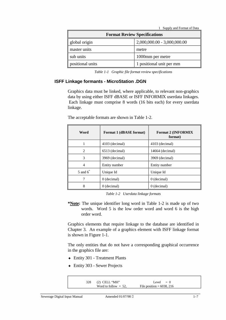
1 Supply and Format of Data
Sewerage Digital Input Manual Amended 01/07/98 ① 1–7
Format Review Specifications
global origin 2,000,000.00 - 3,000,000.00 master units metre sub units 1000mm per metre positional units 1 positional unit per mm
Table 1-1 Graphic file format review specifications
ISFF Linkage formants - MicroStation .DGN
Graphics data must be linked, where applicable, to relevant non-graphics data by using either ISFF dBASE or ISFF INFORMIX userdata linkages. Each linkage must comprise 8 words (16 bits each) for every userdata linkage.
The acceptable formats are shown in Table 1-2.
Word Format 1 (dBASE format) Format 2 (INFORMIX format)
1 4103 (decimal) 4103 (decimal)
2 6513 (decimal) 14664 (decimal)
3 3969 (decimal) 3969 (decimal)
4 Entity number Entity number
5 and 6* Unique Id Unique Id
7 0 (decimal) 0 (decimal)
8 0 (decimal) 0 (decimal)
Table 1-2 Userdata linkage formats
*Note: The unique identifier long word in Table 1-2 is made up of two words. Word 5 is the low order word and word 6 is the high order word.
Graphics elements that require linkage to the database are identified in Chapter 3. An example of a graphics element with ISFF linkage format is shown in Figure 1-1.
The only entities that do not have a corresponding graphical occurrence in the graphics file are:
✦ Entity 301 - Treatment Plants
✦ Entity 303 - Sewer Projects
328 (2) CELL “MH” Level = 0 Word to follow = 52, File position = 6038, 216
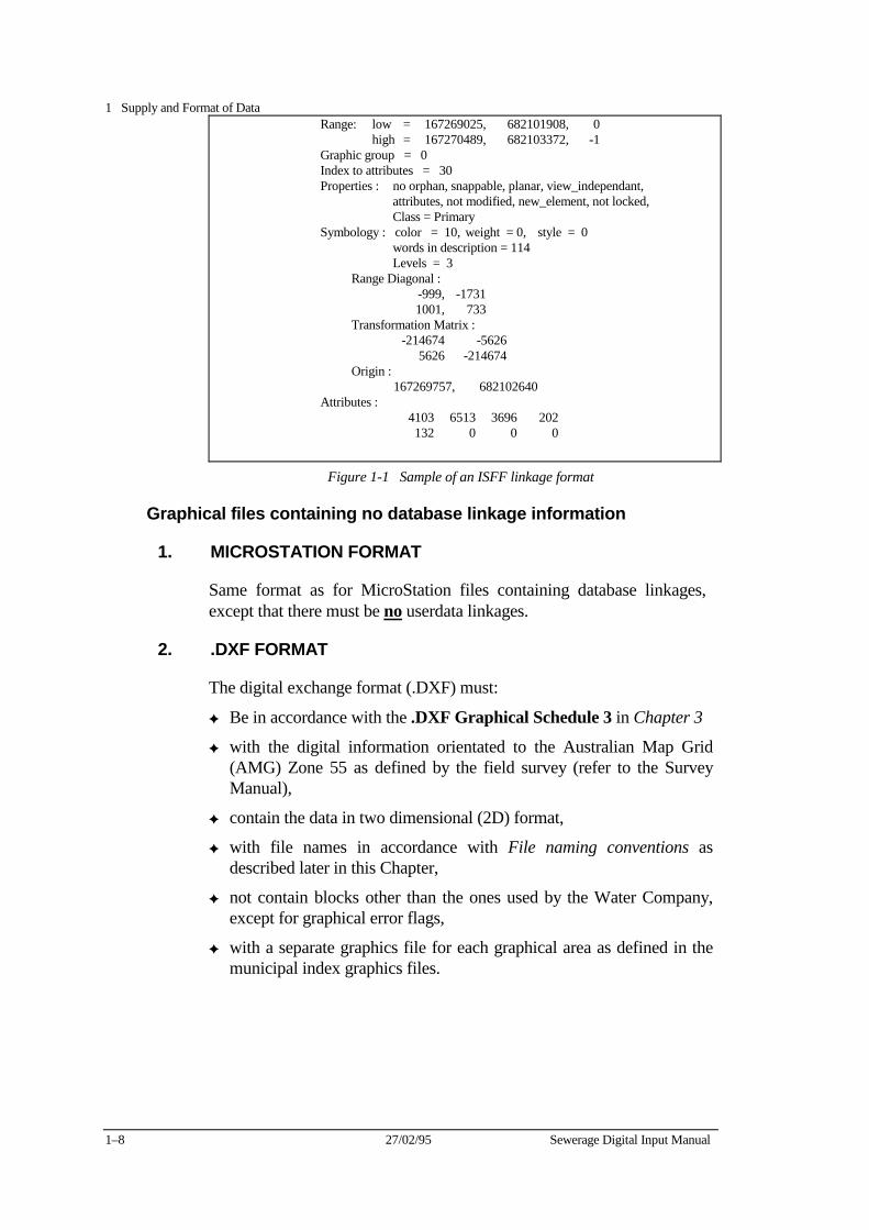
1 Supply and Format of Data
1–8 27/02/95 Sewerage Digital Input Manual
Range: low = 167269025, 682101908, 0 high = 167270489, 682103372, -1 Graphic group = 0 Index to attributes = 30 Properties : no orphan, snappable, planar, view_independant, attributes, not modified, new_element, not locked, Class = Primary Symbology : color = 10, weight = 0, style = 0 words in description = 114 Levels = 3 Range Diagonal : -999, -1731 1001, 733 Transformation Matrix : -214674 -5626 5626 -214674 Origin : 167269757, 682102640 Attributes : 4103 6513 3696 202 132 0 0 0
Figure 1-1 Sample of an ISFF linkage format
Graphical files containing no database linkage information
1. MICROSTATION FORMAT
Same format as for MicroStation files containing database linkages, except that there must be no userdata linkages.
2. .DXF FORMAT
The digital exchange format (.DXF) must:
✦ Be in accordance with the .DXF Graphical Schedule 3 in Chapter 3
✦ with the digital information orientated to the Australian Map Grid (AMG) Zone 55 as defined by the field survey (refer to the Survey Manual),
✦ contain the data in two dimensional (2D) format,
✦ with file names in accordance with File naming conventions as described later in this Chapter,
✦ not contain blocks other than the ones used by the Water Company, except for graphical error flags,
✦ with a separate graphics file for each graphical area as defined in the municipal index graphics files.
1 Supply and Format of Data
Sewerage Digital Input Manual Amended 01/07/98 ① 1–9
File naming conventions Each job has a ten digit file reference number which is the Water Company’s File Management System (FMS) number. For example : 8012371084 (used for subdivisions).
The file naming convention is to drop the first four digits from the file reference number (eg 8012) and add a two digit number (01, 02, etc) to the end to indicate the stage number of the paricular subdivision, For example: 37108401.
Database files
Database files - Linked .DGN
For database files, the filename must have an extension that relates to the relevant entity number. For example, 37108401.305 (for sewerage pipe sections), 37108401.308 (for sewerage access chamber), etc.
Database files (associated with graphical files not having a database linkage)
The database file for Access chambers, Pipes and Branches must have an extension of .asc. The ASCII file for the associated treatment plant must have the extension of .301. For example: 37108401.asc and 37108401.301
Property Service List files
Property Service List files are named in the same manner as other database files except the suffix has a .PSL extension.
For example: 37108401.PSL.
Graphics files
MicroStation graphics files must have a .SW1 extension, For example: 37108401.SW1
.DXF files must have a .DXF extension, For example: 37108401.DXF.
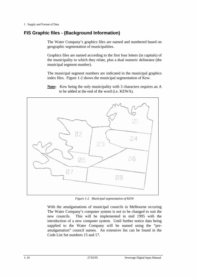
1 Supply and Format of Data
1–10 27/02/95 Sewerage Digital Input Manual
FIS Graphic files - (Background Information)
The Water Company’s graphics files are named and numbered based on geographic segmentation of municipalities.
Graphics files are named according to the first four letters (in capitals) of the municipality to which they relate, plus a dual numeric delineator (the municipal segment number).
The municipal segment numbers are indicated in the municipal graphics index files. Figure 1-2 shows the municipal segmentation of Kew.
Note: Kew being the only municipality with 3 characters requires an A to be added at the end of the word (i.e. KEWA).
Figure 1-2 Municipal segmentation of KEW
With the amalgamations of municipal councils in Melbourne occuring The Water Company’s computer system is not to be changed to suit the new councils. This will be implemented in mid 1995 with the introduction of a new computer system. Until further notice data being supplied to the Water Company will be named using the “pre-amalgamation” council names. An extensive list can be found in the Code List Set numbers 15 and 17.
1 Supply and Format of Data
Sewerage Digital Input Manual Amended 01/07/98 ① 1–11
Data transfer
Formats and media
Data must be delivered in a virus free, non-compressed or non-zipped format, to the Water Company on the following medium.
✦ PC DOS dataset, where:
− the media is a 3.5″ double sided high density diskette
The information must not be supplied in a compressed or zipped format.
Other formats will not be accepted unless previously arranged with the Water Company.
Batches
All data relating to one job must appear where practicable on a single diskette. However when a job crosses municipal boundaries, the data for each municipality must be supplied on a separate media.
Only one job and one discipline (ie sewer, not water) is to be supplied on one media (eg diskette). Additional jobs and/or disciplines are to be supplied on separate media.
A batch of data must contain at least one graphics file and all applicable database files. Database files containing no records are not required.
Mapbase graphics are not to be included.
Documentation which indicates the following, must accompany each batch of data:
✦ a listing of files contained on the media,
✦ the manner in which data was written to the media,
✦ how the data should be retrieved,
✦ the municipality and FIS file number(s),
✦ a plot at scale 1:500 of the graphical file including mapbase,
✦ the total length of sewer pipes in the project,
✦ the total number of property service branches in the project.

1 Supply and Format of Data
1–12 27/02/95 Sewerage Digital Input Manual
Sewerage Digital Input Manual 17/07/2002 2–1
Chapter 2 Database Specifications The Water Company’s sewerage database is made up of a number of entities. An entity is a database table consisting of a number of attributes. These attributes describe different aspects of the entity.
For example, a pipe is an entity (number 305) The pipes material type, size, date of construction etc are some of it’s attributes.
Each entity in the sewerage database has a unique number and each attribute of that entity is identified by a fiend name.
For example, entity 303 - Sewerage Project has seven attribute field names:
✦ a unique identifier,
✦ owner entity number,
✦ owner unique identifier,
✦ sewer name,
✦ section number,
✦ reticulation area number,
✦ reticulation extension number.
A database table can be seen as a set of rows and columns. The attributes are the columns of the table. The rows are the actual occurrences that are stored in the table.
Sewerage database structure The Water Company’s sewerage database is structured hierarchically so that each entity is linked to entities higher up in the database structure using a unique identifier.
For example:
✦ The Treatment Plant entity 301 is at the top of the hierarchy and therefore is not owned by any other entity
✦ The Sewer Project entity 303 owns the Access chamber entity 308 which in turn owns the Pumping Station entity 315 and the Emergency Relief Structure 318.
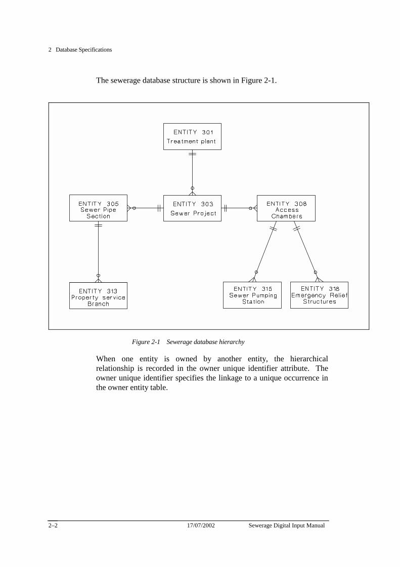
2 Database Specifications
17/07/2002 Sewerage Digital Input Manual 2–2
The sewerage database structure is shown in Figure 2-1.
Figure 2-1 Sewerage database hierarchy
When one entity is owned by another entity, the hierarchical relationship is recorded in the owner unique identifier attribute. The owner unique identifier specifies the linkage to a unique occurrence in the owner entity table.
2 Database Specifications
Sewerage Digital Input Manual 17/07/2002 2–3
Database schedule 1 - MicroStation DGN with Linkages
The following schedule describes the specifications of the database entities and attributes that are required by the Water Company.
Each of the tables in this schedule are set out to indicate information required, they have seven columns: ✦ attribute number, ✦ attribute name, ✦ attribute format, ✦ attribute default value, ✦ attribute FIS references, ✦ whether the attribute must be unique, ✦ usage notes.
Attribute formats
The format of the attributes in the database schedule are as follows:
✦ the first character of the format string is the attribute type:
− I = integer (right justified)
− C = integer derived from to the FIS code list (right justified)
− F = floating point (real) number (right justified)
− A = alphanumeric character (left justified)
✦ the remainder of the format string refers to the field width and the number of decimal places for real numbers.
For example:
• I10 indicates that the attribute value must be an integer of up to ten characters. The field must be 10 characters wide.
• F8.3 indicates that the attribute value must be a floating point number with up to four numbers before the decimal point and up to three numbers following the decimal point. The field must be eight characters wide including the decimal point.
• A3 indicates that the attribute value must be alphanumeric and up to three characters wide. The field must be 3 characters wide.
Attribute format values that are not applicable must be filled with blank spaces i.e. the fields must contain the correct number of characters.
2 Database Specifications
17/07/2002 Sewerage Digital Input Manual 2–4
Default values
There are two types of default values listed in the database schedule:
Mandatory defaults
Mandatory defaults are attribute values that are required by the database and link entities.
The omission of mandatory defaults can cause the Water Company software procedures to fail and may result in non-conformance’s being issued.
Convention dependent defaults
Convention dependent defaults must be used to maintain the consistency of database records.
FIS Reference
The FIS reference column in the database schedule provides four types of reference, which are defined as follows:
✦ AN(nn) indicates that the attribute:
− is an alphanumeric field nn characters wide, where nn equals the number specified in the format field.
− has an alphanumeric reference designated by the Water Company Facilities Information System (FIS).
✦ C(nnn) or C(nnn)/C(mmm) indicates that the attribute is derived from code list (nnn) and/or code list (mmm). Refer to Code lists later in this section.
✦ I(nnnn) indicates the internal storage space allocated for integer values in the FIS database.
✦ F indicates that the attribute value is a floating point number.
FIS Unique criteria
The unique criteria indicates whether a unique value is required by the Water Company in this field.
Attributes requiring a unique value are indicated by an asterisk(❋❋❋❋ ).
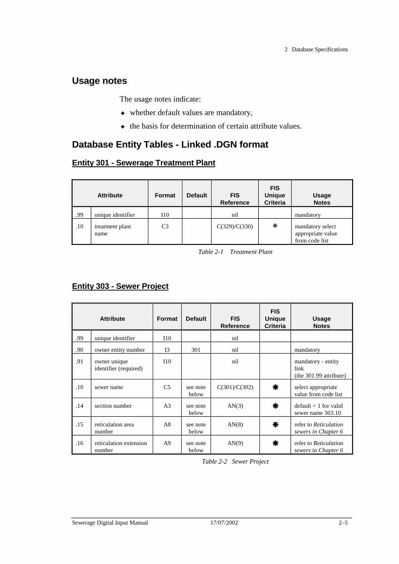
2 Database Specifications
Sewerage Digital Input Manual 17/07/2002 2–5
Usage notes
The usage notes indicate:
✦ whether default values are mandatory,
✦ the basis for determination of certain attribute values.
Database Entity Tables - Linked .DGN format
Entity 301 - Sewerage Treatment Plant
Attribute
Format
Default
FIS
Reference
FIS Unique Criteria
Usage Notes
.99 unique identifier I10 nil mandatory
.10 treatment plant name
C3 C(329)/C(330) ❋ mandatory select appropriate value from code list
Table 2-1 Treatment Plant
Entity 303 - Sewer Project
Attribute
Format
Default
FIS
Reference
FIS Unique Criteria
Usage Notes
.99 unique identifier I10 nil
.90 owner entity number I3 301 nil mandatory
.91 owner unique identifier (required)
I10 nil mandatory - entity link (the 301.99 attribute)
.10 sewer name C5 see note below
C(301)/C(302) ❋❋❋❋ select appropriate value from code list
.14 section number A3 see note below
AN(3) ❋❋❋❋ default = 1 for valid sewer name 303.10
.15 reticulation area number
A8 see note below
AN(8) ❋❋❋❋ refer to Reticulation sewers in Chapter 6
.16 reticulation extension number
A9 see note below
AN(9) ❋❋❋❋ refer to Reticulation sewers in Chapter 6
Table 2-2 Sewer Project

2 Database Specifications
17/07/2002 Sewerage Digital Input Manual 2–6
Note: if the following criteria are not met, the occurrence will be rejected. The database format only allows a sewer project to be input as one of the following.
✦ a sewer name and section number (303.10 and 303.14), or
✦ a reticulation area number (303.15), or
✦ a reticulation extension number (303.16)
Sewer projects must not be entered as a combination of these projects.
Attribute format values that are not applicable must be filled with blank spaces and the values must contain the correct number of characters.

2 Database Specifications
Sewerage Digital Input Manual 17/07/2002 2–7
Entity 305 - Sewer Pipe Section
Attribute
Format
Default
FIS
Reference
FIS Unique Criteria
Usage Notes
.99 unique identifier I10 nil mandatory
.90 owner entity number I3 303 nil mandatory
.91 owner unique identifier (required)
I10 nil mandatory - entity link (the 303.99 attribute)
.10 downstream structure number
A13 AN(13) ❋❋❋❋ refer to Numbering access chambers in Chapter 7
.11 downstream invert level F8.3 F refer to Invert levels in Chapter 8
.12 upstream structure number
A13 AN(13) ❋❋❋❋ refer to Numbering access chambers in Chapter 7
.13 upstream invert level F8.3 F refer to Invert levels in Chapter 8
.14 conduit shape C3 C(39)/C(40) select appropriate value from code list
.16 nominal size of conduit C5 C(41) select appropriate value from code list
.18 conduit length F8.3 F
.20 conduit material C3 C(43)/C(44) select appropriate value from code list
.21 conduit lining C3 6 C(45)/C(46) select appropriate value from code list
.23 conduit coating C3 6 C(45)/C(46) select appropriate value from code list
.28 conduit joint packing C3 C(51)/C(52) select appropriate value from code list
.33 excavation method C3 C(63)/C(64) select method from code list that relates to majority of pipe section
Table 2-3-1 Sewer pipe sections
Continued on the next page
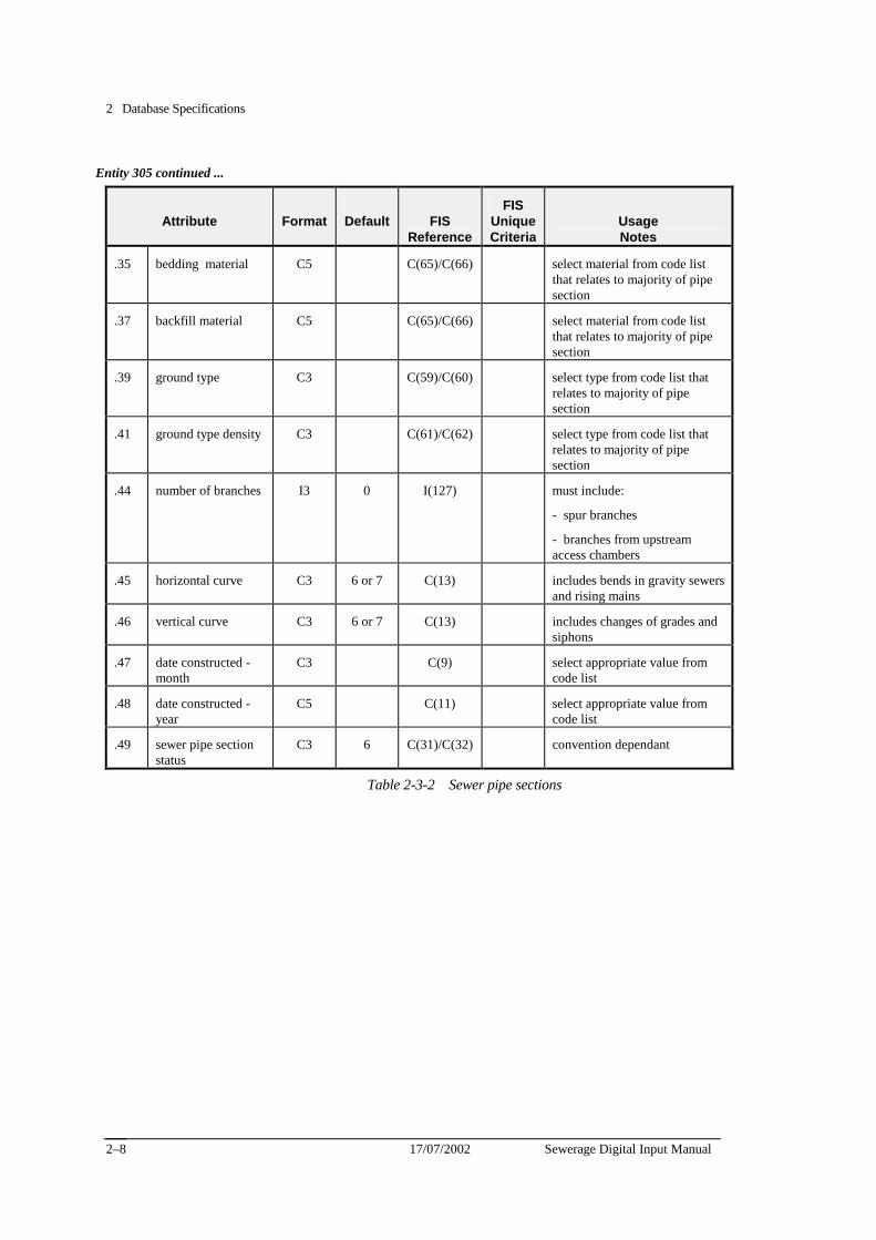
2 Database Specifications
17/07/2002 Sewerage Digital Input Manual 2–8
Entity 305 continued ...
Attribute
Format
Default
FIS
Reference
FIS UniqueCriteria
Usage Notes
.35 bedding material C5 C(65)/C(66) select material from code list that relates to majority of pipe section
.37 backfill material C5 C(65)/C(66) select material from code list that relates to majority of pipe section
.39 ground type C3 C(59)/C(60) select type from code list that relates to majority of pipe section
.41 ground type density C3 C(61)/C(62) select type from code list that relates to majority of pipe section
.44 number of branches I3 0 I(127) must include:
- spur branches
- branches from upstream access chambers
.45 horizontal curve C3 6 or 7 C(13) includes bends in gravity sewers and rising mains
.46 vertical curve C3 6 or 7 C(13) includes changes of grades and siphons
.47 date constructed - month
C3 C(9) select appropriate value from code list
.48 date constructed -year
C5 C(11) select appropriate value from code list
.49 sewer pipe section status
C3 6 C(31)/C(32) convention dependant
Table 2-3-2 Sewer pipe sections
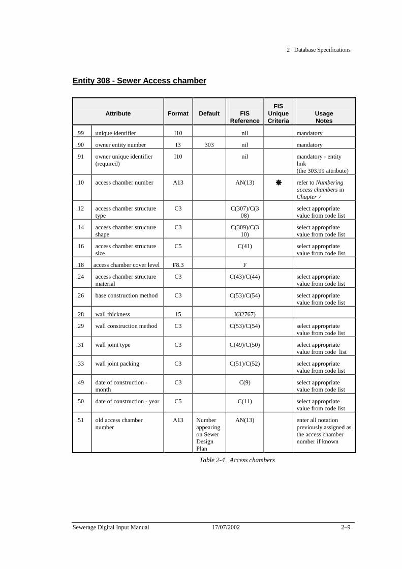
2 Database Specifications
Sewerage Digital Input Manual 17/07/2002 2–9
Entity 308 - Sewer Access chamber
Attribute
Format
Default
FIS
Reference
FIS Unique Criteria
Usage Notes
.99 unique identifier I10 nil mandatory
.90 owner entity number I3 303 nil mandatory
.91 owner unique identifier (required)
I10 nil mandatory - entity link (the 303.99 attribute)
.10 access chamber number A13 AN(13) ❋❋❋❋ refer to Numbering access chambers in Chapter 7
.12 access chamber structure type
C3 C(307)/C(308)
select appropriate value from code list
.14 access chamber structure shape
C3 C(309)/C(310)
select appropriate value from code list
.16 access chamber structure size
C5 C(41) select appropriate value from code list
.18 access chamber cover level F8.3 F
.24 access chamber structure material
C3 C(43)/C(44) select appropriate value from code list
.26 base construction method C3 C(53)/C(54) select appropriate value from code list
.28 wall thickness 15 I(32767)
.29 wall construction method C3 C(53)/C(54) select appropriate value from code list
.31 wall joint type C3 C(49)/C(50) select appropriate value from code list
.33 wall joint packing C3 C(51)/C(52) select appropriate value from code list
.49 date of construction - month
C3 C(9) select appropriate value from code list
.50 date of construction - year C5 C(11) select appropriate value from code list
.51 old access chamber number
A13 Number appearing on Sewer Design Plan
AN(13) enter all notation previously assigned as the access chamber number if known
Table 2-4 Access chambers
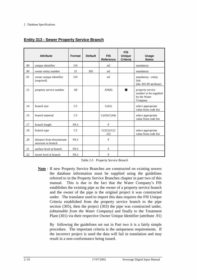
2 Database Specifications
17/07/2002 Sewerage Digital Input Manual 2–10
Entity 313 - Sewer Property Service Branch
Attribute
Format
Default
FIS
Reference
FIS Unique Criteria
Usage Notes
.99 unique identifier I10 nil mandatory
.90 owner entity number I3 305 nil mandatory
.91 owner unique identifier (required)
I10 nil mandatory - entity link (the 305.99 attribute)
.11 property service number A8 AN(8) ❋❋❋❋ property service number to be supplied by the Water Company
.14 branch size C5 C(41) select appropriate value from code list
.15 branch material C3 C(43)/C(44) select appropriate value from code list
.17 branch length F8.3 F
.18 branch type C3 C(321)/C(322)
select appropriate value from code list
.20 distance from downstream structure to branch
F8.3 F
.21 surface level at branch F8.3 F
.22 invert level at branch F8.3 F
Table 2-5 Property Service Branch
Note : If new Property Service Branches are constructed on existing sewers the database information must be supplied using the guidelines referred to in the Property Service Branches chapter in part two of this manual. This is due to the fact that the Water Company’s FIS establishes the existing pipe as the owner of a property service branch and the owner of the pipe is the original project it was constructed under. The translator used to import this data requires the FIS Unique Criteria established from the property service branch to the pipe section (305), then the project (303) the pipe was constructed under, (obtainable from the Water Company) and finally to the Treatment Plant (301) via their respective Owner Unique Identifier (attribute .91)
By following the guidelines set out in Part two it is a fairly simple procedure. The important criteria is the uniqueness requirements. If the incorrect project is used the data will fail in translation and may result in a non-conformance being issued.
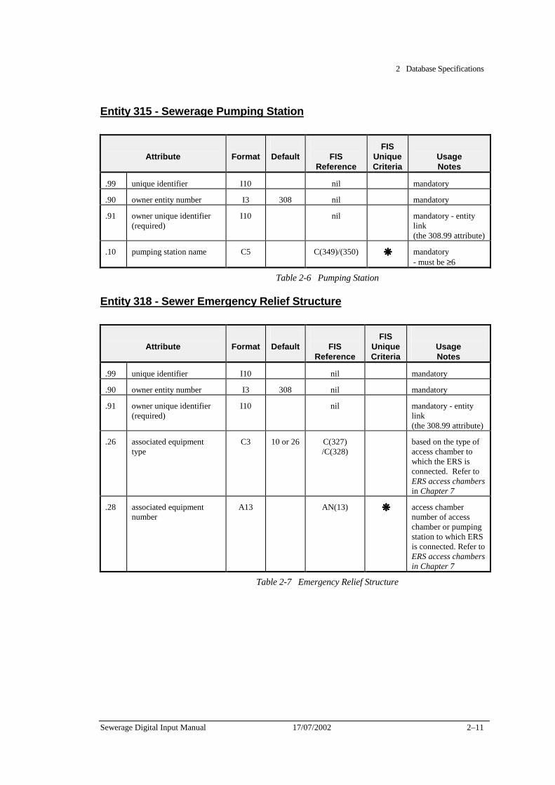
2 Database Specifications
Sewerage Digital Input Manual 17/07/2002 2–11
Entity 315 - Sewerage Pumping Station
Attribute
Format
Default
FIS
Reference
FIS Unique Criteria
Usage Notes
.99 unique identifier I10 nil mandatory
.90 owner entity number I3 308 nil mandatory
.91 owner unique identifier (required)
I10 nil mandatory - entity link (the 308.99 attribute)
.10 pumping station name C5 C(349)/(350) ❋❋❋❋ mandatory - must be ≥6
Table 2-6 Pumping Station
Entity 318 - Sewer Emergency Relief Structure
Attribute
Format
Default
FIS
Reference
FIS Unique Criteria
Usage Notes
.99 unique identifier I10 nil mandatory
.90 owner entity number I3 308 nil mandatory
.91 owner unique identifier (required)
I10 nil mandatory - entity link (the 308.99 attribute)
.26 associated equipment type
C3 10 or 26 C(327) /C(328)
based on the type of access chamber to which the ERS is connected. Refer to ERS access chambers in Chapter 7
.28 associated equipment number
A13 AN(13) ❋❋❋❋ access chamber number of access chamber or pumping station to which ERS is connected. Refer to ERS access chambers in Chapter 7
Table 2-7 Emergency Relief Structure
2 Database Specifications
17/07/2002 Sewerage Digital Input Manual 2–12
Database schedule 2 (associated with graphical files not having a database linkage)
This section describes the specifications of the database entities and attributes that must be supplied by the Consultant to the Water Company, when the graphical files are not linked to the database information.
The following tables define the required attribute information, format of each attribute and format of each record.
The conventions used in the tables are:
✦ The letters in the tables (A,B,C etc) describe the columns that are used if the input is performed through a spreadsheet,
✦ The Col. and Width are the start and width of each of each column,
✦ The Used Col. shows a number in brackets which is the number of digits actually used by the Water Company (not necessarily the same as the column width in the data file). When the type is a floating point decimal, the number before the decimal defines the number of columns to be used including the decimal point and the number after the decimal point defines the position of the decimal point (i.e. 10.3 is a real number of up to 6 digits before the decimal point, followed by the decimal point and three more digits),
✦ The valid types are known as:
A alphanumeric left justified e.g. |ABC123 | I integer right justified | 1234| F floating point decimal right justified | 234.567| C code derived from left justified |12 | the FIS code list
✦ Attr. relates to the Water Company’s FIS database attribute number,
✦ Attribute Name specifies the attribute information required,
✦ Default specifies the value that must be used for the data file record type identifier, contained within the first three columns of any record and code values that should be used from the FIS code list, if there is nothing more appropriate,
✦ Code List identifies the code set that must be used,
✦ Spacing has been inserted between each attribute required, to assist readability. This inserted space is one character wide and any character can be used for spacing (commas or semi-colons are recommended).
2 Database Specifications
Sewerage Digital Input Manual 17/07/2002 2–13
Access chambers, Pipes and Branch Connections
The ASCII file must be set out with the Sewer Project details in the first row.
The second row contains the first Downstream access chamber details followed by the Upstream access chamber details for the first pipe section in the third row.
The fourth row contains the first Pipe section details which runs between the preceding access chambers. If the pipe section contains a horizontal/vertical curve the details will be recorded on the next row (row five)
If no horizontal/vertical curves are present then the fifth row contains the Property Service branch details for the preceding Pipe section. This is the first branch upstream from the pipes Downstream access chamber.
The sixth, seventh etc contains the rest of the Property Service branches for the preceding Pipe section. Once all PS branches for this respective pipe section have been recorded the next row will contain the next Pipe section’s Downstream access chamber details, then the Upstream access chambers, Pipe section, Property Service branches etc until all of the project has been included in the ASCII file.
For an example of an ASCII file refer to Appendix C.
If the ASCII file is supplied with all Entities grouped together and not as indicated above the batch of data will be rejected and may result in a non- conformance being placed on the particular job.
Note: If an existing the project connects into an existing access chamber the database record is still required, describing only the AMG position, access chamber name and cover level. The existing access chamber is not to be shown in the graphics file.
If new Property Service Branches are constructed on existing sewers the database information must be supplied in field note form and not included in the ASCII files. This is due to the fact that the Water Company’s FIS establishes the existing pipe as the owner of a property service branch and the owner of the pipe is the original project it was constructed under. The translator used to transform the unlinked data as set out in this section does not allow for multiple projects. For further information

2 Database Specifications
17/07/2002 Sewerage Digital Input Manual 2–14
refer to the Property Service Branches chapter in part two (Guidelines) of this manual.
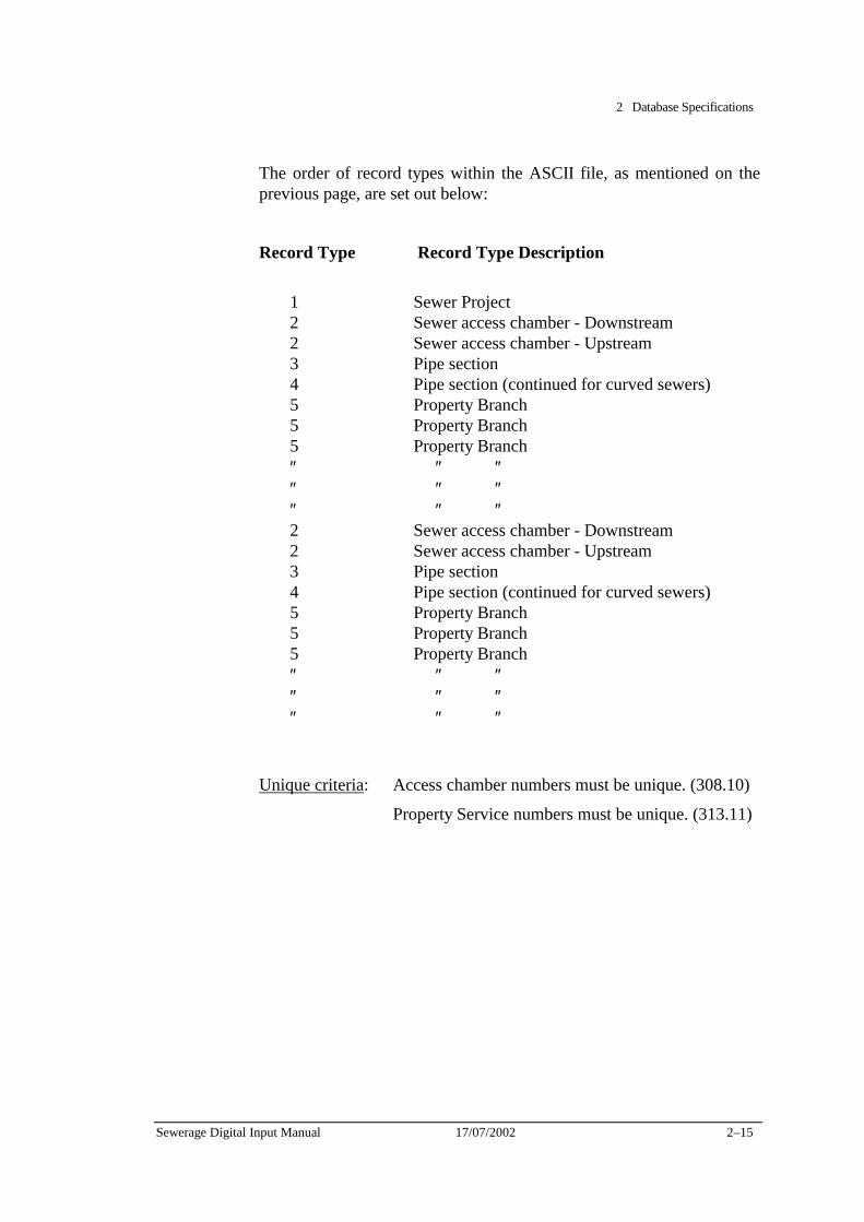
2 Database Specifications
Sewerage Digital Input Manual 17/07/2002 2–15
The order of record types within the ASCII file, as mentioned on the previous page, are set out below:
Record Type Record Type Description
1 Sewer Project 2 Sewer access chamber - Downstream 2 Sewer access chamber - Upstream 3 Pipe section 4 Pipe section (continued for curved sewers) 5 Property Branch 5 Property Branch 5 Property Branch ″ ″ ″ ″ ″ ″ ″ ″ ″ 2 Sewer access chamber - Downstream 2 Sewer access chamber - Upstream 3 Pipe section 4 Pipe section (continued for curved sewers) 5 Property Branch 5 Property Branch 5 Property Branch ″ ″ ″ ″ ″ ″ ″ ″ ″
Unique criteria: Access chamber numbers must be unique. (308.10)
Property Service numbers must be unique. (313.11)
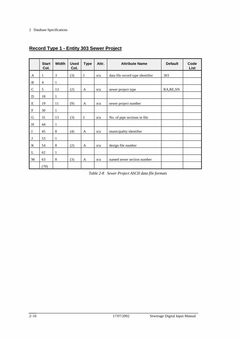
2 Database Specifications
17/07/2002 Sewerage Digital Input Manual 2–16
Record Type 1 - Entity 303 Sewer Project
Start Col.
Width Used Col.
Type Attr. Attribute Name Default Code List
A 1 3 (3) I n/a data file record type identifier 303
B 4 1
C 5 13 (2) A n/a sewer project type RA,RE,SN
D 18 1
E 19 11 (9) A n/a sewer project number
F 30 1
G 31 13 (3) I n/a No. of pipe sections in file
H 44 1
I 45 8 (4) A n/a municipality identifier
J 53 1
K 54 8 (2) A n/a design file number
L 62 1
M 63 8 (3) A n/a named sewer section number
(70)
Table 2-8 Sewer Project ASCII data file formats
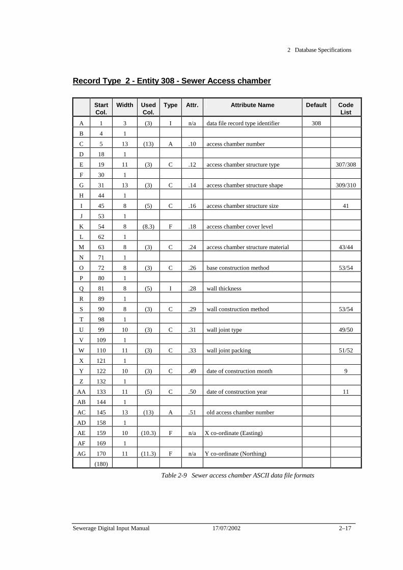
2 Database Specifications
Sewerage Digital Input Manual 17/07/2002 2–17
Record Type 2 - Entity 308 - Sewer Access chamber
Start Col.
Width Used Col.
Type Attr. Attribute Name Default Code List
A 1 3 (3) I n/a data file record type identifier 308
B 4 1
C 5 13 (13) A .10 access chamber number
D 18 1
E 19 11 (3) C .12 access chamber structure type 307/308
F 30 1
G 31 13 (3) C .14 access chamber structure shape 309/310
H 44 1
I 45 8 (5) C .16 access chamber structure size 41
J 53 1
K 54 8 (8.3) F .18 access chamber cover level
L 62 1
M 63 8 (3) C .24 access chamber structure material 43/44
N 71 1
O 72 8 (3) C .26 base construction method 53/54
P 80 1
Q 81 8 (5) I .28 wall thickness
R 89 1
S 90 8 (3) C .29 wall construction method 53/54
T 98 1
U 99 10 (3) C .31 wall joint type 49/50
V 109 1
W 110 11 (3) C .33 wall joint packing 51/52
X 121 1
Y 122 10 (3) C .49 date of construction month 9
Z 132 1
AA 133 11 (5) C .50 date of construction year 11
AB 144 1
AC 145 13 (13) A .51 old access chamber number
AD 158 1
AE 159 10 (10.3) F n/a X co-ordinate (Easting)
AF 169 1
AG 170 11 (11.3) F n/a Y co-ordinate (Northing)
(180)
Table 2-9 Sewer access chamber ASCII data file formats

2 Database Specifications
17/07/2002 Sewerage Digital Input Manual 2–18
Record Type 3 - Entity 305 - Sewer Pipe Section
Start Col.
Width Used Col.
Type Attr. Attribute Name Default Code List
A 1 3 (3) I n/a data file record type identifier 305
B 4 1
C 5 13 (13) A .10 downstream structure number
D 18 1
E 19 11 (8.3) F .11 downstream invert level
F 30 1
G 31 13 (13) A. .12 upstream structure number
H 44 1
I 45 8 (8.3) F .13 upstream invert level
J 53 1
K 54 8 (3) C .14 conduit shape 39/40
L 62 1
M 63 8 (5) C .16 nominal size of conduit 41
N 71 1
O 72 8 (8.3) F .18 conduit length
P 80 1
Q 81 8 (3) C .20 conduit material 43/44
R 89 1
S 90 8 (3) C .21 conduit lining 6 45/46
T 98 1
U 99 10 (3) C .23 conduit coating 6 45/46
V 109 1
W 110 11 (3) C .28 conduit joint packing 51/52
X 121 1
Y 122 10 (3) C .33 excavation method 63/64
Z 132 1
AA 133 11 (5) C .35 bedding material 65/66
AB 144 1
AC 145 13 (5) C .37 backfill material 65/66
Table 2-10-1 Sewer pipe section ASCII data file formats Continued on the next page
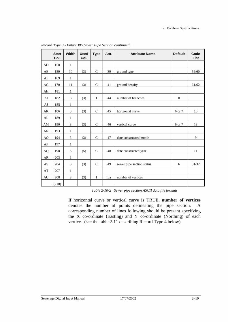
2 Database Specifications
Sewerage Digital Input Manual 17/07/2002 2–19
Record Type 3 - Entity 305 Sewer Pipe Section continued...
Start Col.
Width Used Col.
Type Attr. Attribute Name Default Code List
AD 158 1
AE 159 10 (3) C .39 ground type 59/60
AF 169 1
AG 170 11 (3) C .41 ground density 61/62
AH 181 1
AI 182 3 (3) I .44 number of branches 0
AJ 185 1
AK 186 3 (3) C .45 horizontal curve 6 or 7 13
AL 189 1
AM 190 3 (3) C .46 vertical curve 6 or 7 13
AN 193 1
AO 194 3 (3) C .47 date constructed month 9
AP 197 1
AQ 198 5 (5) C .48 date constructed year 11
AR 203 1
AS 204 3 (3) C .49 sewer pipe section status 6 31/32
AT 207 1
AU 208 3 (3) I n/a number of vertices
(210)
Table 2-10-2 Sewer pipe section ASCII data file formats
If horizontal curve or vertical curve is TRUE, number of vertices denotes the number of points delineating the pipe section. A corresponding number of lines following should be present specifying the X co-ordinate (Easting) and Y co-ordinate (Northing) of each vertice. (see the table 2-11 describing Record Type 4 below).
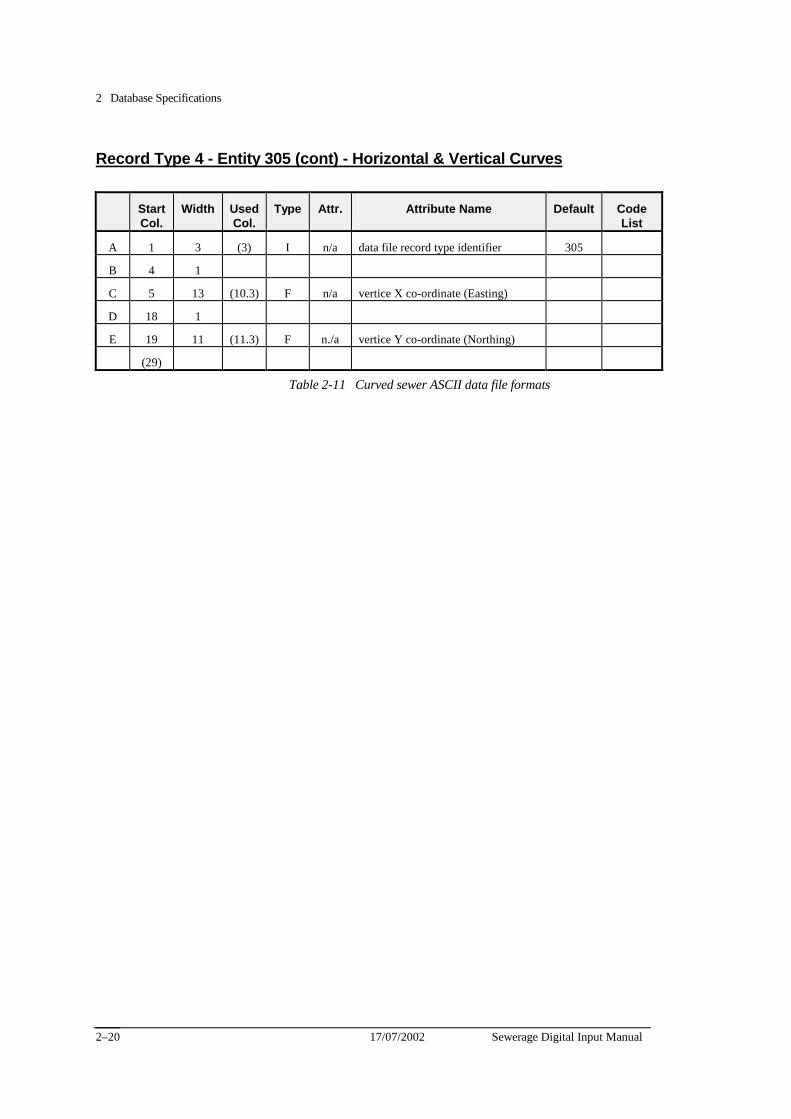
2 Database Specifications
17/07/2002 Sewerage Digital Input Manual 2–20
Record Type 4 - Entity 305 (cont) - Horizontal & Vertical Curves
Start Col.
Width Used Col.
Type Attr. Attribute Name Default Code List
A 1 3 (3) I n/a data file record type identifier 305
B 4 1
C 5 13 (10.3) F n/a vertice X co-ordinate (Easting)
D 18 1
E 19 11 (11.3) F n./a vertice Y co-ordinate (Northing)
(29)
Table 2-11 Curved sewer ASCII data file formats
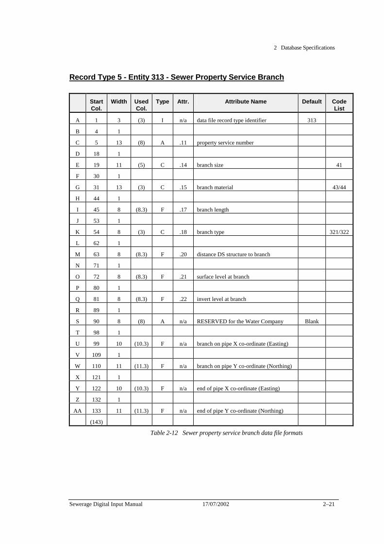
2 Database Specifications
Sewerage Digital Input Manual 17/07/2002 2–21
Record Type 5 - Entity 313 - Sewer Property Service Branch
Start Col.
Width Used Col.
Type Attr. Attribute Name Default Code List
A 1 3 (3) I n/a data file record type identifier 313
B 4 1
C 5 13 (8) A .11 property service number
D 18 1
E 19 11 (5) C .14 branch size 41
F 30 1
G 31 13 (3) C .15 branch material 43/44
H 44 1
I 45 8 (8.3) F .17 branch length
J 53 1
K 54 8 (3) C .18 branch type 321/322
L 62 1
M 63 8 (8.3) F .20 distance DS structure to branch
N 71 1
O 72 8 (8.3) F .21 surface level at branch
P 80 1
Q 81 8 (8.3) F .22 invert level at branch
R 89 1
S 90 8 (8) A n/a RESERVED for the Water Company Blank
T 98 1
U 99 10 (10.3) F n/a branch on pipe X co-ordinate (Easting)
V 109 1
W 110 11 (11.3) F n/a branch on pipe Y co-ordinate (Northing)
X 121 1
Y 122 10 (10.3) F n/a end of pipe X co-ordinate (Easting)
Z 132 1
AA 133 11 (11.3) F n/a end of pipe Y co-ordinate (Northing)
(143)
Table 2-12 Sewer property service branch data file formats
2 Database Specifications
17/07/2002 Sewerage Digital Input Manual 2–22
Database verification requirements
Required verification checks
Database attributes must be verified to ensure data accuracy
These checks may be carried out at the point of entry or at the output stage.
The following suggestions are offered as a means of checking a number of attributes.
Uniqueness criteria checks
These checks will ensure that the following numbers are unique:
✦ Sewer Project
✦ Access chamber number
✦ Property Service number
✦ Pumping Station name
✦ ERS number
Sewer pipe section invert levels, size and length
Table 2-13 lists expected grade values to aid the verification of sewer pipe section invert levels (305.11 & .13), conduit size (305.16) and conduit length (305.18).
This verification check functions as a warning that one or several items may have been incorrectly entered. It is based upon a general relationship between pipe size and grade, the expected ranges for which are specified in Table 2-13. Note that an allowance for grades outside these ranges has been included.
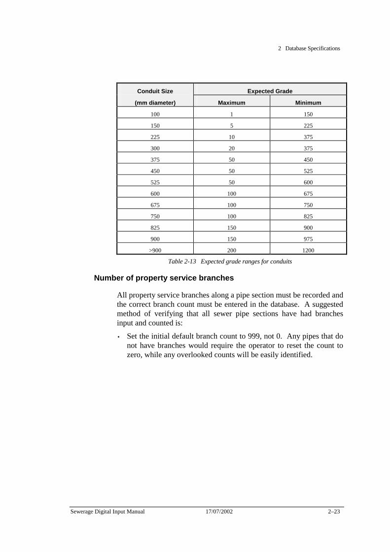
2 Database Specifications
Sewerage Digital Input Manual 17/07/2002 2–23
Conduit Size Expected Grade
(mm diameter) Maximum Minimum
100 1 150
150 5 225
225 10 375
300 20 375
375 50 450
450 50 525
525 50 600
600 100 675
675 100 750
750 100 825
825 150 900
900 150 975
>900 200 1200
Table 2-13 Expected grade ranges for conduits
Number of property service branches
All property service branches along a pipe section must be recorded and the correct branch count must be entered in the database. A suggested method of verifying that all sewer pipe sections have had branches input and counted is:
• Set the initial default branch count to 999, not 0. Any pipes that do not have branches would require the operator to reset the count to zero, while any overlooked counts will be easily identified.
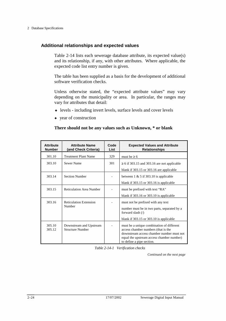
2 Database Specifications
17/07/2002 Sewerage Digital Input Manual 2–24
Additional relationships and expected values
Table 2-14 lists each sewerage database attribute, its expected value(s) and its relationship, if any, with other attributes. Where applicable, the expected code list entry number is given.
The table has been supplied as a basis for the development of additional software verification checks.
Unless otherwise stated, the “expected attribute values” may vary depending on the municipality or area. In particular, the ranges may vary for attributes that detail:
✦ levels - including invert levels, surface levels and cover levels
✦ year of construction
There should not be any values such as Unknown, * or blank
Attribute Number
Attribute Name (and Check Criteria)
Code List
Expected Values and Attribute Relationships
301.10 Treatment Plant Name 329 must be ≥ 6
303.10 Sewer Name 301 ≥ 6 if 303.15 and 303.16 are not applicable
blank if 303.15 or 303.16 are applicable
303.14 Section Number - between 1 & 5 if 303.10 is applicable
blank if 303.15 or 303.16 is applicable
303.15 Reticulation Area Number - must be prefixed with text “RA”
blank if 303.16 or 303.10 is applicable
303.16 Reticulation Extension Number
- must not be prefixed with any text
number must be in two parts, separated by a forward slash (/)
blank if 303.15 or 303.10 is applicable
305.10 305.12
Downstream and Upstream Structure Number
- must be a unique combination of different access chamber numbers (that is the downstream access chamber number must not equal the upstream access chamber number) to define a pipe section.
Table 2-14-1 Verification checks
Continued on the next page
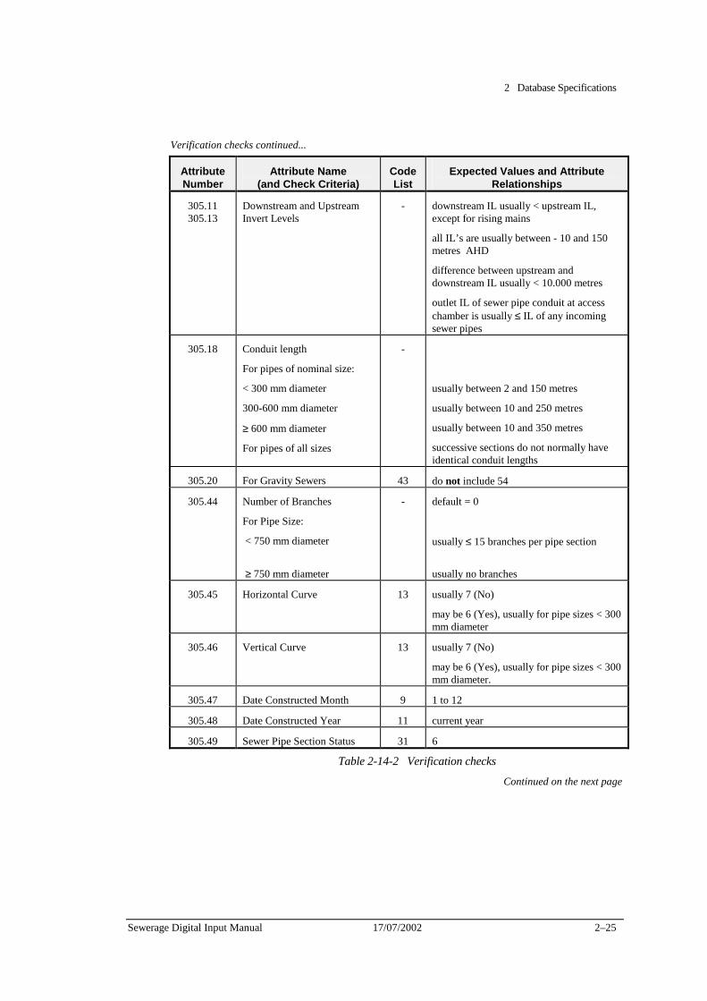
2 Database Specifications
Sewerage Digital Input Manual 17/07/2002 2–25
Verification checks continued...
Attribute Number
Attribute Name (and Check Criteria)
Code List
Expected Values and Attribute Relationships
305.11 305.13
Downstream and Upstream Invert Levels
- downstream IL usually < upstream IL, except for rising mains
all IL’s are usually between - 10 and 150 metres AHD
difference between upstream and downstream IL usually < 10.000 metres
outlet IL of sewer pipe conduit at access chamber is usually ≤ IL of any incoming sewer pipes
305.18 Conduit length
For pipes of nominal size:
< 300 mm diameter
300-600 mm diameter
≥ 600 mm diameter
For pipes of all sizes
-
usually between 2 and 150 metres
usually between 10 and 250 metres
usually between 10 and 350 metres
successive sections do not normally have identical conduit lengths
305.20 For Gravity Sewers 43 do not include 54
305.44 Number of Branches
For Pipe Size:
< 750 mm diameter
≥ 750 mm diameter
- default = 0
usually ≤ 15 branches per pipe section
usually no branches
305.45 Horizontal Curve 13 usually 7 (No)
may be 6 (Yes), usually for pipe sizes < 300 mm diameter
305.46 Vertical Curve 13 usually 7 (No)
may be 6 (Yes), usually for pipe sizes < 300 mm diameter.
305.47 Date Constructed Month 9 1 to 12
305.48 Date Constructed Year 11 current year
305.49 Sewer Pipe Section Status 31 6
Table 2-14-2 Verification checks
Continued on the next page
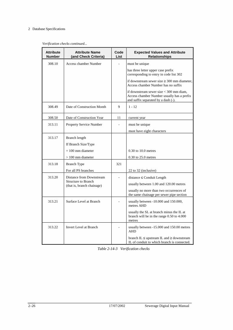
2 Database Specifications
17/07/2002 Sewerage Digital Input Manual 2–26
Verification checks continued...
Attribute Number
Attribute Name (and Check Criteria)
Code List
Expected Values and Attribute Relationships
308.10 Access chamber Number - must be unique
has three letter upper case prefix corresponding to entry in code list 302
if downstream sewer size ≥ 300 mm diameter, Access chamber Number has no suffix
if downstream sewer size < 300 mm diam, Access chamber Number usually has a prefix and suffix separated by a dash (-).
308.49 Date of Construction Month 9 1 - 12
308.50 Date of Construction Year 11 current year
313.11 Property Service Number - must be unique
must have eight characters
313.17 Branch length
If Branch Size/Type
= 100 mm diameter
> 100 mm diameter
0.30 to 10.0 metres
0.30 to 25.0 metres
313.18 Branch Type
For all PS branches
321
22 to 32 (inclusive)
313.20 Distance from Downstream Structure to Branch (that is, branch chainage)
- distance ≤ Conduit Length
usually between 1.00 and 120.00 metres
usually no more than two occurrences of the same chainage per sewer pipe section
313.21 Surface Level at Branch - usually between -10.000 and 150.000, metres AHD
usually the SL at branch minus the IL at branch will be in the range 0.50 to 4.000 metres
313.22 Invert Level at Branch - usually between -15.000 and 150.00 metres AHD
branch IL ≤ upstream IL and ≥ downstream IL of conduit to which branch is connected.
Table 2-14-3 Verification checks
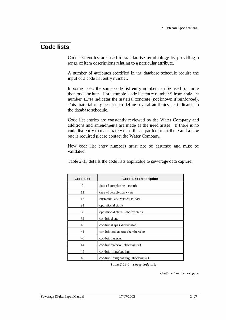
2 Database Specifications
Sewerage Digital Input Manual 17/07/2002 2–27
Code lists Code list entries are used to standardise terminology by providing a range of item descriptions relating to a particular attribute.
A number of attributes specified in the database schedule require the input of a code list entry number.
In some cases the same code list entry number can be used for more than one attribute. For example, code list entry number 9 from code list number 43/44 indicates the material concrete (not known if reinforced). This material may be used to define several attributes, as indicated in the database schedule.
Code list entries are constantly reviewed by the Water Company and additions and amendments are made as the need arises. If there is no code list entry that accurately describes a particular attribute and a new one is required please contact the Water Company.
New code list entry numbers must not be assumed and must be validated.
Table 2-15 details the code lists applicable to sewerage data capture.
Code List Code List Description
9 date of completion - month
11 date of completion - year
13 horizontal and vertical curves
31 operational status
32 operational status (abbreviated)
39 conduit shape
40 conduit shape (abbreviated)
41 conduit and access chamber size
43 conduit material
44 conduit material (abbreviated)
45 conduit lining/coating
46 conduit lining/coating (abbreviated)
Table 2-15-1 Sewer code lists
Continued on the next page

2 Database Specifications
17/07/2002 Sewerage Digital Input Manual 2–28
Code Lists continued... Code List Code List Description
49 access chamber and conduit joint type
50 access chamber joint type (abbreviated)
51 conduit joint packing
52 conduit joint packing (abbreviated)
53 access chamber wall construction method
54 access chamber wall construction method (abbreviated)
59 soil type
60 soil type (abbreviated)
61 soil density
62 soil density (abbreviated)
63 construction method
64 construction method (abbreviated)
65 bedding and backfill material
66 bedding and backfill material (abbreviated)
301 named sewer names
302 named sewer names (abbreviated)
307 sewerage access chamber types
308 sewerage access chamber types (abbreviated)
309 sewerage access chamber shapes
310 sewerage access chamber shapes (abbreviated)
321 sewerage property service branch type
322 sewerage property service branch type (abbreviated)
327 associated equipment type (ERS etc)
328 associated equipment number
329 sewerage treatment plant name
330 sewerage treatment plant number
349 sewer pumping station names
350 sewer pumping station number
Table 2-15-2 Sewer code lists

2 Database Specifications
Sewerage Digital Input Manual 17/07/2002 2–29
Sewerage Digital Input Manual 17/07/2002 3–1
Chapter 3 Graphical Specifications This Chapter contains the specifications for the graphical representation of elements in sewer files. It includes:
✦ verification requirements for graphics files,
✦ a level and layer structure for sewer elements
✦ symbology for sewer elements
✦ associated software specifications
✦ a graphical library of cells used in sewer data capture
The Water Company uses Intergraph .DGN format graphics files. The information is stored in each graphics file in levels, or layers, enabling different types of information to be displayed at any one time.
Certain graphical elements have a link to the FIS database.
Each graphics file has 63 levels.
.DGN formatted graphics as set out in the tables in this chapter are the preferred format that the Water Company would like to receive any graphical information.
The order of preference the Water Company would like digital information supplied is:
1. MicroStation .DGN format with linked database information as per Database Schedule 1 in Chapter 2.
2. MicroStation .DGN format without linked database information as per Database Schedule 2 in Chapter 2.
3. .DXF format without linked database information as per Database Schedule 2 in Chapter 2.
.DXF format graphics files have to be converted to MicroStation .DGN format by the Water Company to enable them to be merged into the FIS.
This chapter contains the specifications for the graphical representation of elements in sewerage files. It is split into three schedules:
Graphics Schedule 1 - For MicroStation linked .DGN format Graphics Schedule 2 - For MicroStation unlinked .DGN format Graphics Schedule 3 - For unlinked .DXF format
3 Graphical Specifications
3–2 17/07/2002 Sewerage Digital Input Manual
Graphics Schedule 1 - For MicroStation in Linked .DGN format
This Schedule contains the specifications for the graphical representation of elements with database linked in sewerage file. It includes:
✦ Intergraph element type details,
✦ verification requirements for graphic files,
✦ a listing of level structures,
✦ a listing of symbologies,
✦ related software specifications,
✦ a graphic library of cells used in sewer data capture.
Intergraph element specifications
All sewerage elements must be assigned the Intergraph Element Class “Primary”.
Acceptable Intergraph Element Types are specified in Table 3-1
Version 5.x of MicroStation has new element types which are unknown in earlier versions. The Water Company recommends that the compatibility switch be set to version 3 or version 4 to avoid possible problems.
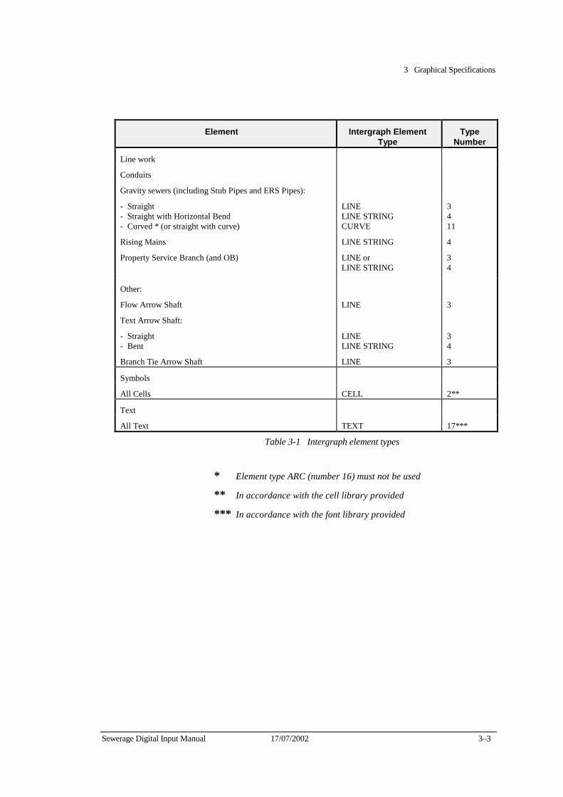
3 Graphical Specifications
Sewerage Digital Input Manual 17/07/2002 3–3
Element Intergraph Element
Type Type
Number
Line work
Conduits
Gravity sewers (including Stub Pipes and ERS Pipes):
- Straight - Straight with Horizontal Bend - Curved * (or straight with curve)
Rising Mains
Property Service Branch (and OB)
LINE LINE STRING CURVE
LINE STRING
LINE or LINE STRING
3 4 11
4
3 4
Other:
Flow Arrow Shaft
Text Arrow Shaft:
- Straight - Bent
Branch Tie Arrow Shaft
LINE
LINE LINE STRING
LINE
3
3 4
3
Symbols
All Cells CELL 2**
Text
All Text TEXT 17***
Table 3-1 Intergraph element types
* Element type ARC (number 16) must not be used
** In accordance with the cell library provided
*** In accordance with the font library provided

3 Graphical Specifications
3–4 17/07/2002 Sewerage Digital Input Manual
Graphic file verification requirements
Consultants must verify the basic file structure of all graphics design files submitted to the Water Company. Verification checks must be carried out by consultants in the following manner.
The Edit Graphics (EDG) verification command sequence required in the VAX environment is:
$ EDG/READ filename
edg> SET SEARCH/ALL
edg> SET VERIFY/LENGTH
edg> EOF
If the output from this command sequence is <End of Design>, the basic file structure is acceptable.
Output other than the above indicates file structure problems. File structure problems are displayed in the form of diagnostic messages related to the first element not satisfying the verification procedure. These are major errors and prevent the file from being graphically displayable. Minor errors however may not affect graphical display but can cause subsequent plotting problems.
The equivalent verification in the version 3.x MicroStation PC environment is achieved with the following EDG command sequence:
edg> SET SEARCH/ALL
edg> SET MODE/VERIFY
edg> FIND END
Output from this command sequence should be <End of Design>.
In the version 4.x MicroStation PC environment, the command sequence must be expanded as follows:
edg> SET SEARCH/ALL
edg> SET MODE/VERIFY
edg> SET VERIFY/LENGTH
edg> FIND END
Output from this command sequence should be <End of Design>.
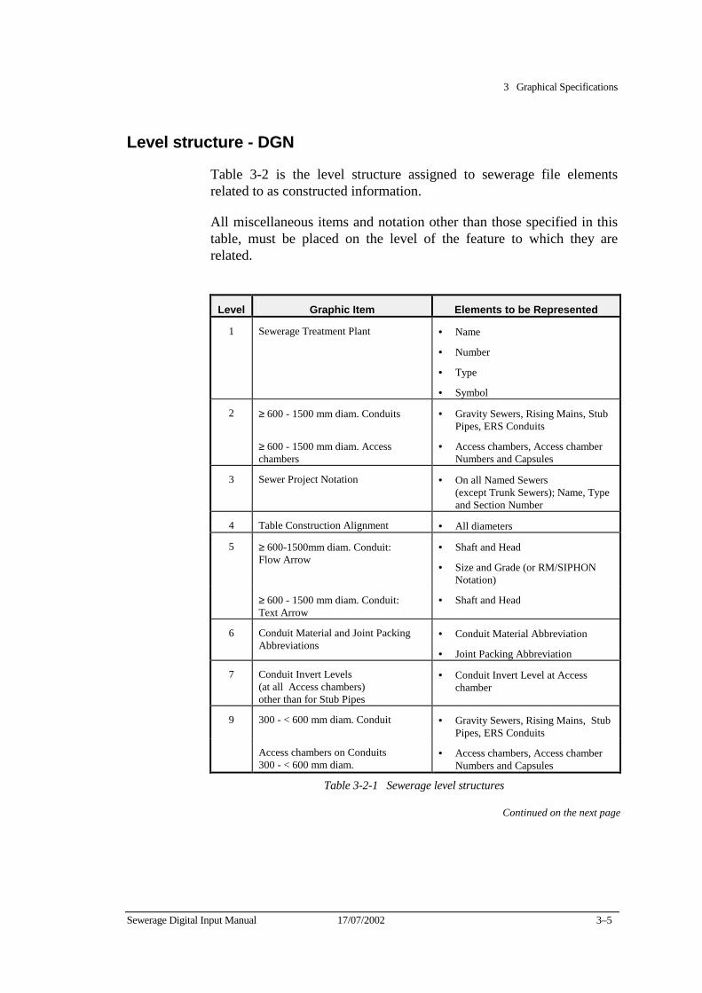
3 Graphical Specifications
Sewerage Digital Input Manual 17/07/2002 3–5
Level structure - DGN
Table 3-2 is the level structure assigned to sewerage file elements related to as constructed information.
All miscellaneous items and notation other than those specified in this table, must be placed on the level of the feature to which they are related.
Level Graphic Item Elements to be Represented
1 Sewerage Treatment Plant • Name
• Number
• Type
• Symbol
2 ≥ 600 - 1500 mm diam. Conduits • Gravity Sewers, Rising Mains, Stub Pipes, ERS Conduits
≥ 600 - 1500 mm diam. Access chambers
• Access chambers, Access chamber Numbers and Capsules
3 Sewer Project Notation • On all Named Sewers (except Trunk Sewers); Name, Type and Section Number
4 Table Construction Alignment • All diameters
5 ≥ 600-1500mm diam. Conduit: Flow Arrow
• Shaft and Head
• Size and Grade (or RM/SIPHON Notation)
≥ 600 - 1500 mm diam. Conduit: Text Arrow
• Shaft and Head
6 Conduit Material and Joint Packing Abbreviations
• Conduit Material Abbreviation
• Joint Packing Abbreviation
7 Conduit Invert Levels (at all Access chambers) other than for Stub Pipes
• Conduit Invert Level at Access chamber
9 300 - < 600 mm diam. Conduit • Gravity Sewers, Rising Mains, Stub Pipes, ERS Conduits
Access chambers on Conduits 300 - < 600 mm diam.
• Access chambers, Access chamber Numbers and Capsules
Table 3-2-1 Sewerage level structures
Continued on the next page

3 Graphical Specifications
3–6 17/07/2002 Sewerage Digital Input Manual
Sewer Level structures continued...
Level Graphic Item Elements to be Represented
10 300 - < 600 mm diam. Conduit: Flow Arrow
• Shaft and Head
• Size and Grade (or RM/SIPHON Notation)
300 - < 600mm diam. Conduit: Text Arrow
• Shaft and Head
12 < 300mm diam. Conduit • Gravity Sewers, Rising Mains, Stub Pipes, ERS Conduits
Access chambers on Conduit < 300 mm diam
• Access chambers, Access chamber Numbers and Capsules
13 < 300 mm diam. Conduit: Flow Arrow
• Shaft and Head
• Size and Grade (or RM/SIPHON Notation)
<300mm diam. Conduit: Text Arrow
• Shaft and Head
14 Sewer Conduit Offset • Sewer Offset Dimensions and Pointers
Combined Drain Notation • CD Text
15 Rising Main Notation (all sizes) • Rising Main Notation
16 Property Service Number • The PS number supplied by the Water Company
Boundary Trap Notation • BT Text
17 Access chamber Chainage & Miscellaneous Notation
• Pipe Section or Access chamber Features
18 Combined CD & BT Text • BTCD Text
21 Features on Conduit: •
Change of Grade • Text, Chainage and Symbol
Horizontal Curve or bend • Tangent Point (Text, Chainage & Symbol)
Miscellaneous Invert Level • Invert Levels other than those on Level 7 (Stub Pipe, Table Construction, etc.)
Miscellaneous Chainage • Along Conduits (for example, running chainage or Rising Mains and Independent Sewers)
Table 3-2-2 Sewerage level structures
Continued on the next page
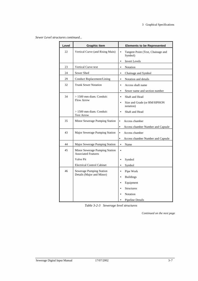
3 Graphical Specifications
Sewerage Digital Input Manual 17/07/2002 3–7
Sewer Level structures continued...
Level Graphic Item Elements to be Represented
22 Vertical Curve (and Rising Main) • Tangent Point (Text, Chainage and Symbol)
• Invert Levels
23 Vertical Curve text • Notation
24 Sewer Shed • Chainage and Symbol
29 Conduct Replacement/Lining • Notation and details
32 Trunk Sewer Notation • Access shaft name
• Sewer name and section number
34 > 1500 mm diam. Conduit: Flow Arrow
• Shaft and Head
• Size and Grade (or RM/SIPHON notation)
> 1500 mm diam. Conduit: Text Arrow
• Shaft and Head
35 Minor Sewerage Pumping Station • Access chamber
• Access chamber Number and Capsule
43 Major Sewerage Pumping Station • Access chamber
• Access chamber Number and Capsule
44 Major Sewerage Pumping Station • Name
45 Minor Sewerage Pumping Station Associated Features
•
Valve Pit • Symbol
Electrical Control Cabinet • Symbol
46 Sewerage Pumping Station Details (Major and Minor)
• Pipe Work
• Buildings
• Equipment
• Structures
• Notation
• Pipeline Details
Table 3-2-3 Sewerage level structures
Continued on the next page

3 Graphical Specifications
3–8 17/07/2002 Sewerage Digital Input Manual
Sewer Level structures continued...
Level Graphic Item Elements to be Represented 47 Sewerage Treatment Plant Details • Pipe Work
• Buildings
• Equipment
• Structure
• Labels and Notation
48 Sewer Detention Tank • Structure, Pipe Work, Name
49 Property Service Branches, Oblique Branches (OB’s), Associated Features and Notation
• Branch/OB Pipe
• Inspection Opening at End of Branch
• Branch Tie (Dimension and Notation)
• Branch Projection Line
• Branch Tie Arrow (Shaft and Head)
• Chainage of Branch or OB from downstream Access chamber
• Branch Details - NSL, - IL, - EP Length
50 Features on Branch: Jump-Up (JU) • Text, and Symbol Oblique Branch (OB) • Text and Chainage Bend • Text and Chainage
57 Other Authority Sewers • All details (Line work, Symbols, Text) Excluding: - “Abandoned Sewer”
Notation and Symbols - File Reference
Numbers
58 Private Sewers • All details (Line work, Symbols, Text) Excluding: - “Abandoned Sewer”
Notation and Symbols - File Reference
Numbers
59 Private Rising Mains • All details (Line work, Symbols, Text) Excluding: - “Abandoned Sewer”
Notation and Symbols - File Reference
Numbers
63 Graphical Flags • “Problem”, and “Edge Matching” Symbols
Table 3-2-4 Sewerage level structures
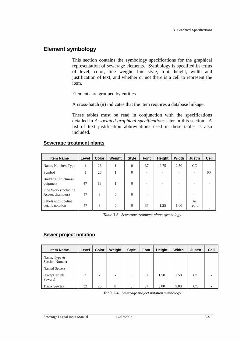
3 Graphical Specifications
Sewerage Digital Input Manual 17/07/2002 3–9
Element symbology
This section contains the symbology specifications for the graphical representation of sewerage elements. Symbology is specified in terms of level, color, line weight, line style, font, height, width and justification of text, and whether or not there is a cell to represent the item.
Elements are grouped by entities.
A cross-hatch (#) indicates that the item requires a database linkage.
These tables must be read in conjunction with the specifications detailed in Associated graphical specifications later in this section. A list of text justification abbreviations used in these tables is also included.
Sewerage treatment plants
Item Name Level Color Weight Style Font Height Width Just’n Cell
Name, Number, Type 1 26 1 0 37 2.75 2.50 CC -
Symbol 1 26 1 0 - - - - PP
Building/Structures/Equipment
47
13
1
0
-
-
-
-
-
Pipe Work (including Access chambers)
47
3
0
0
-
-
-
-
-
Labels and Pipeline details notation
47
3
0
0
37
1.25
1.00
As req’d
-
Table 3-3 Sewerage treatment plants symbology
Sewer project notation
Item Name Level Color Weight Style Font Height Width Just’n Cell
Name, Type & Section Number
Named Sewers
(except Trunk Sewers)
3
-
-
0
37
1.50
1.50
CC
-
Trunk Sewers 32 26 0 0 37 5.00 5.00 CC -
Table 3-4 Sewerage project notation symbology
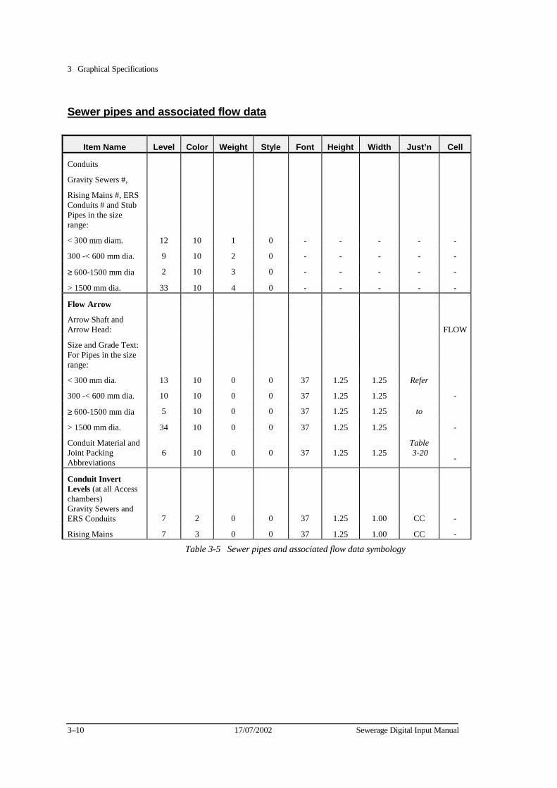
3 Graphical Specifications
3–10 17/07/2002 Sewerage Digital Input Manual
Sewer pipes and associated flow data
Item Name Level Color Weight Style Font Height Width Just’n Cell
Conduits
Gravity Sewers #,
Rising Mains #, ERS Conduits # and Stub Pipes in the size range:
< 300 mm diam. 12 10 1 0 - - - - -
300 -< 600 mm dia. 9 10 2 0 - - - - -
≥ 600-1500 mm dia 2 10 3 0 - - - - -
> 1500 mm dia. 33 10 4 0 - - - - -
Flow Arrow
Arrow Shaft and Arrow Head:
FLOW
Size and Grade Text: For Pipes in the size range:
< 300 mm dia. 13 10 0 0 37 1.25 1.25 Refer
300 -< 600 mm dia. 10 10 0 0 37 1.25 1.25 -
≥ 600-1500 mm dia 5 10 0 0 37 1.25 1.25 to
> 1500 mm dia. 34 10 0 0 37 1.25 1.25 -
Conduit Material and Joint Packing Abbreviations
6
10
0
0
37
1.25
1.25
Table 3-20
-
Conduit Invert Levels (at all Access chambers) Gravity Sewers and ERS Conduits
7
2
0
0
37
1.25
1.00
CC
-
Rising Mains 7 3 0 0 37 1.25 1.00 CC -
Table 3-5 Sewer pipes and associated flow data symbology
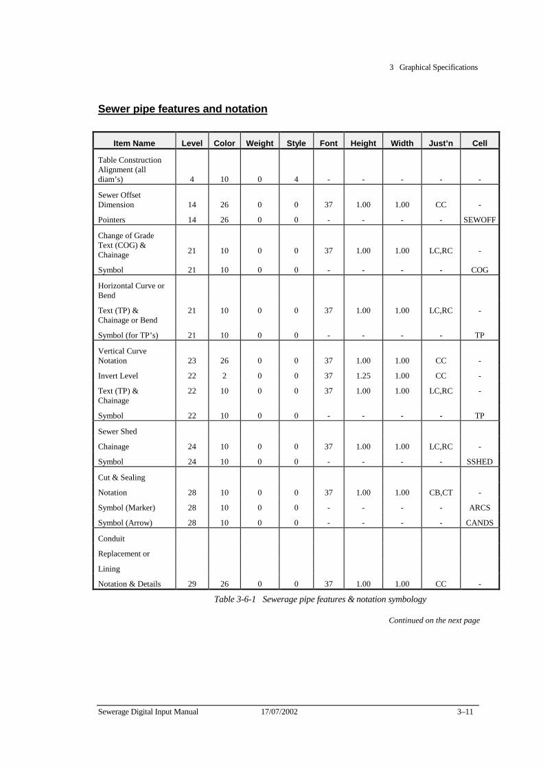
3 Graphical Specifications
Sewerage Digital Input Manual 17/07/2002 3–11
Sewer pipe features and notation
Item Name Level Color Weight Style Font Height Width Just’n Cell
Table Construction Alignment (all diam’s)
4
10
0
4
-
-
-
-
-
Sewer Offset Dimension
14
26
0
0
37
1.00
1.00
CC
-
Pointers 14 26 0 0 - - - - SEWOFF
Change of Grade Text (COG) & Chainage
21
10
0
0
37
1.00
1.00
LC,RC
-
Symbol 21 10 0 0 - - - - COG
Horizontal Curve or Bend
Text (TP) & Chainage or Bend
21 10 0 0 37 1.00 1.00 LC,RC -
Symbol (for TP’s) 21 10 0 0 - - - - TP
Vertical Curve Notation
23
26
0
0
37
1.00
1.00
CC
-
Invert Level 22 2 0 0 37 1.25 1.00 CC -
Text (TP) & Chainage
22 10 0 0 37 1.00 1.00 LC,RC -
Symbol 22 10 0 0 - - - - TP
Sewer Shed
Chainage 24 10 0 0 37 1.00 1.00 LC,RC -
Symbol 24 10 0 0 - - - - SSHED
Cut & Sealing
Notation 28 10 0 0 37 1.00 1.00 CB,CT -
Symbol (Marker) 28 10 0 0 - - - - ARCS
Symbol (Arrow) 28 10 0 0 - - - - CANDS
Conduit
Replacement or
Lining
Notation & Details 29 26 0 0 37 1.00 1.00 CC -
Table 3-6-1 Sewerage pipe features & notation symbology
Continued on the next page

3 Graphical Specifications
3–12 17/07/2002 Sewerage Digital Input Manual
Sewer pipe features & notation continued...
Item Name Level Color Weight Style Font Height Width Just’n Cell
Detention Tank
Name 48 26 0 0 37 2.00 2.00 As Req’d
-
Structure/Pipe Work 48 3 0 0 - - - - -
Text Arrow
Arrow Shaft for pipe in size range:
< 300 mm dia. 13 10 1 1 - - - - -
300 -< 600 mm dia. 10 10 1 1 - - - - -
≥ 600-1500 mm dia 5 10 1 1 - - - - -
> 1500 mm dia. 34 10 1 1 - - - - -
Arrow Head for pipe in size range:
< 300 mm dia. 13 10 0 0 - - - - FLOW
300 -< 600 mm dia. 10 10 0 0 - - - - FLOW
≥ 600-1500 mm dia 5 10 0 0 - - - - FLOW
> 1500 mm dia. 34 10 0 0 - - - - FLOW
Miscellaneous Notation
Sewer &/or Access chamber Feature
17 10 0 0 37 1.20 1.20 As Req’d
-
Misc. Invert Level 21 2 0 0 37 1.00 1.00 CC -
Miscellaneous Chainage
21
10
0
0
37
1.00
1.00
LC,RC -
Other Miscellaneous Notation
(Symbology as specified for individual item notation)
Graphical Flags
Edgematching, Problem, Data Symbols
63
23
Unspecified, but must contain the letter E, or P in a circle of Rad. 4m
4.00
4.00
CC
-
Table 3-6-2 Sewerage pipe features & notation symbology
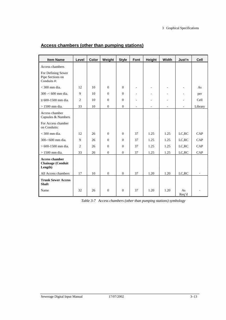
3 Graphical Specifications
Sewerage Digital Input Manual 17/07/2002 3–13
Access chambers (other than pumping stations)
Item Name Level Color Weight Style Font Height Width Just’n Cell
Access chambers
For Defining Sewer Pipe Sections on Conduits #:
< 300 mm dia. 12 10 0 0 - - - - As
300 -< 600 mm dia. 9 10 0 0 - - - - per
≥ 600-1500 mm dia. 2 10 0 0 - - - - Cell
> 1500 mm dia. 33 10 0 0 - - - - Library
Access chamber Capsules & Numbers
For Access chamber on Conduits:
< 300 mm dia. 12 26 0 0 37 1.25 1.25 LC,RC CAP
300-<600 mm dia. 9 26 0 0 37 1.25 1.25 LC,RC CAP
> 600-1500 mm dia. 2 26 0 0 37 1.25 1.25 LC,RC CAP
> 1500 mm dia. 33 26 0 0 37 1.25 1.25 LC,RC CAP
Access chamber Chainage (Conduit Length)
All Access chambers 17 10 0 0 37 1.20 1.20 LC,RC -
Trunk Sewer Access Shaft
Name 32 26 0 0 37 1.20 1.20 As Req’d
-
Table 3-7 Access chambers (other than pumping stations) symbology
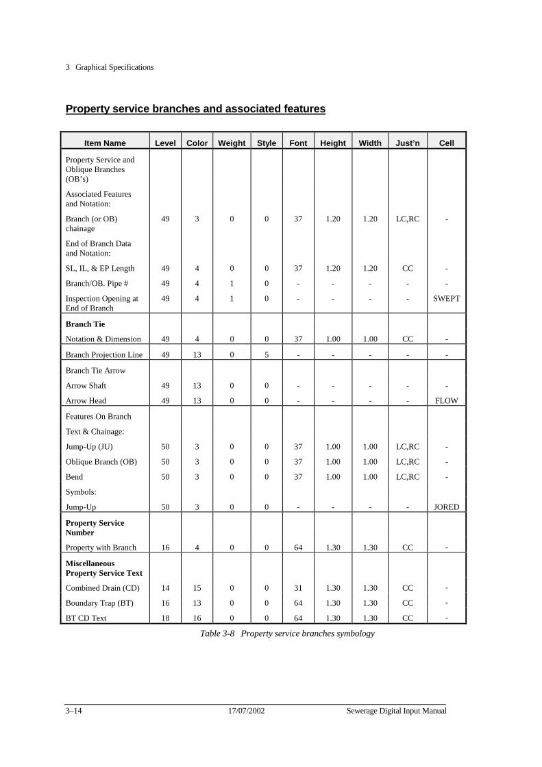
3 Graphical Specifications
3–14 17/07/2002 Sewerage Digital Input Manual
Property service branches and associated features
Item Name Level Color Weight Style Font Height Width Just’n Cell
Property Service and Oblique Branches (OB’s)
Associated Features and Notation:
Branch (or OB) chainage
49 3 0 0 37 1.20 1.20 LC,RC -
End of Branch Data and Notation:
SL, IL, & EP Length 49 4 0 0 37 1.20 1.20 CC -
Branch/OB. Pipe # 49 4 1 0 - - - - -
Inspection Opening at End of Branch
49 4 1 0 - - - - SWEPT
Branch Tie
Notation & Dimension 49 4 0 0 37 1.00 1.00 CC -
Branch Projection Line 49 13 0 5 - - - - -
Branch Tie Arrow
Arrow Shaft 49 13 0 0 - - - - -
Arrow Head 49 13 0 0 - - - - FLOW
Features On Branch
Text & Chainage:
Jump-Up (JU) 50 3 0 0 37 1.00 1.00 LC,RC -
Oblique Branch (OB) 50 3 0 0 37 1.00 1.00 LC,RC -
Bend 50 3 0 0 37 1.00 1.00 LC,RC -
Symbols:
Jump-Up 50 3 0 0 - - - - JORED
Property Service Number
Property with Branch 16 4 0 0 64 1.30 1.30 CC -
Miscellaneous Property Service Text
Combined Drain (CD) 14 15 0 0 31 1.30 1.30 CC -
Boundary Trap (BT) 16 13 0 0 64 1.30 1.30 CC -
BT CD Text 18 16 0 0 64 1.30 1.30 CC -
Table 3-8 Property service branches symbology
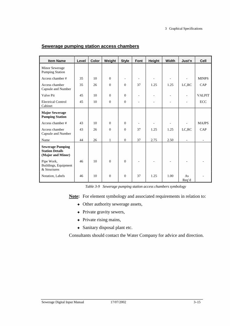
3 Graphical Specifications
Sewerage Digital Input Manual 17/07/2002 3–15
Sewerage pumping station access chambers
Item Name Level Color Weight Style Font Height Width Just’n Cell
Minor Sewerage Pumping Station
Access chamber # 35 10 0 - - - - - MINPS
Access chamber Capsule and Number
35 26 0 0 37 1.25 1.25 LC,RC CAP
Valve Pit 45 10 0 0 - - - - VALPIT
Electrical Control Cabinet
45 10 0 0 - - - - ECC
Major Sewerage Pumping Station
Access chamber # 43 10 0 0 - - - - MAJPS
Access chamber Capsule and Number
43 26 0 0 37 1.25 1.25 LC,RC CAP
Name 44 26 1 0 37 2.75 2.50 - -
Sewerage Pumping Station Details (Major and Minor)
Pipe Work, Buildings, Equipment & Structures
46 10 0 0 - - - - -
Notation, Labels 46 10 0 0 37 1.25 1.00 As Req’d
-
Table 3-9 Sewerage pumping station access chambers symbology
Note: For element symbology and associated requirements in relation to:
✦ Other authority sewerage assets,
✦ Private gravity sewers,
✦ Private rising mains,
✦ Sanitary disposal plant etc.
Consultants should contact the Water Company for advice and direction.
3 Graphical Specifications
3–16 17/07/2002 Sewerage Digital Input Manual
Graphics Schedule 2 - For MicroStation in Unlinked .DGN format
This Schedule is the same as Schedule 1 with the exception the graphical elements must not have any elements with database links in sewerage file.
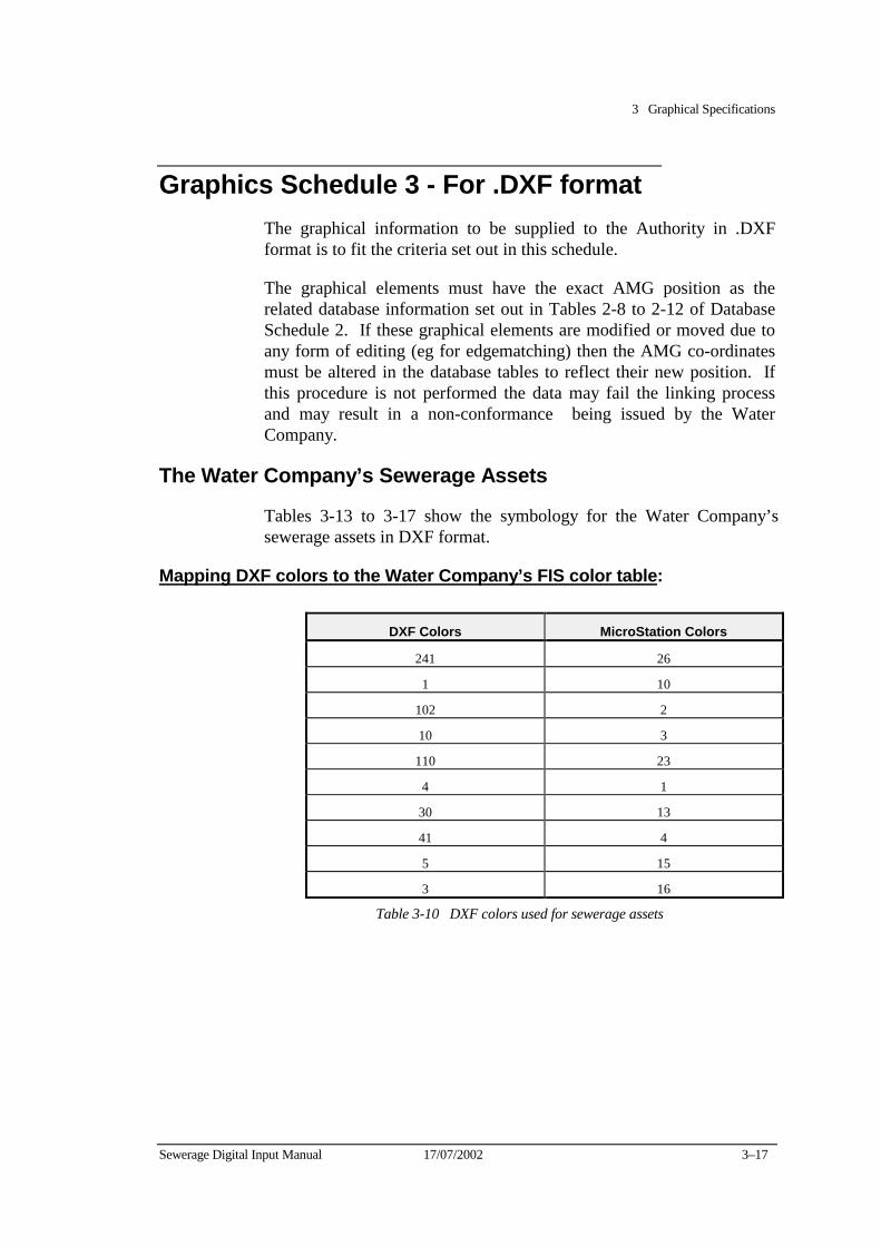
3 Graphical Specifications
Sewerage Digital Input Manual 17/07/2002 3–17
Graphics Schedule 3 - For .DXF format The graphical information to be supplied to the Authority in .DXF format is to fit the criteria set out in this schedule.
The graphical elements must have the exact AMG position as the related database information set out in Tables 2-8 to 2-12 of Database Schedule 2. If these graphical elements are modified or moved due to any form of editing (eg for edgematching) then the AMG co-ordinates must be altered in the database tables to reflect their new position. If this procedure is not performed the data may fail the linking process and may result in a non-conformance being issued by the Water Company.
The Water Company’s Sewerage Assets
Tables 3-13 to 3-17 show the symbology for the Water Company’s sewerage assets in DXF format.
Mapping DXF colors to the Water Company’s FIS color table:
DXF Colors MicroStation Colors
241 26
1 10
102 2
10 3
110 23
4 1
30 13
41 4
5 15
3 16
Table 3-10 DXF colors used for sewerage assets
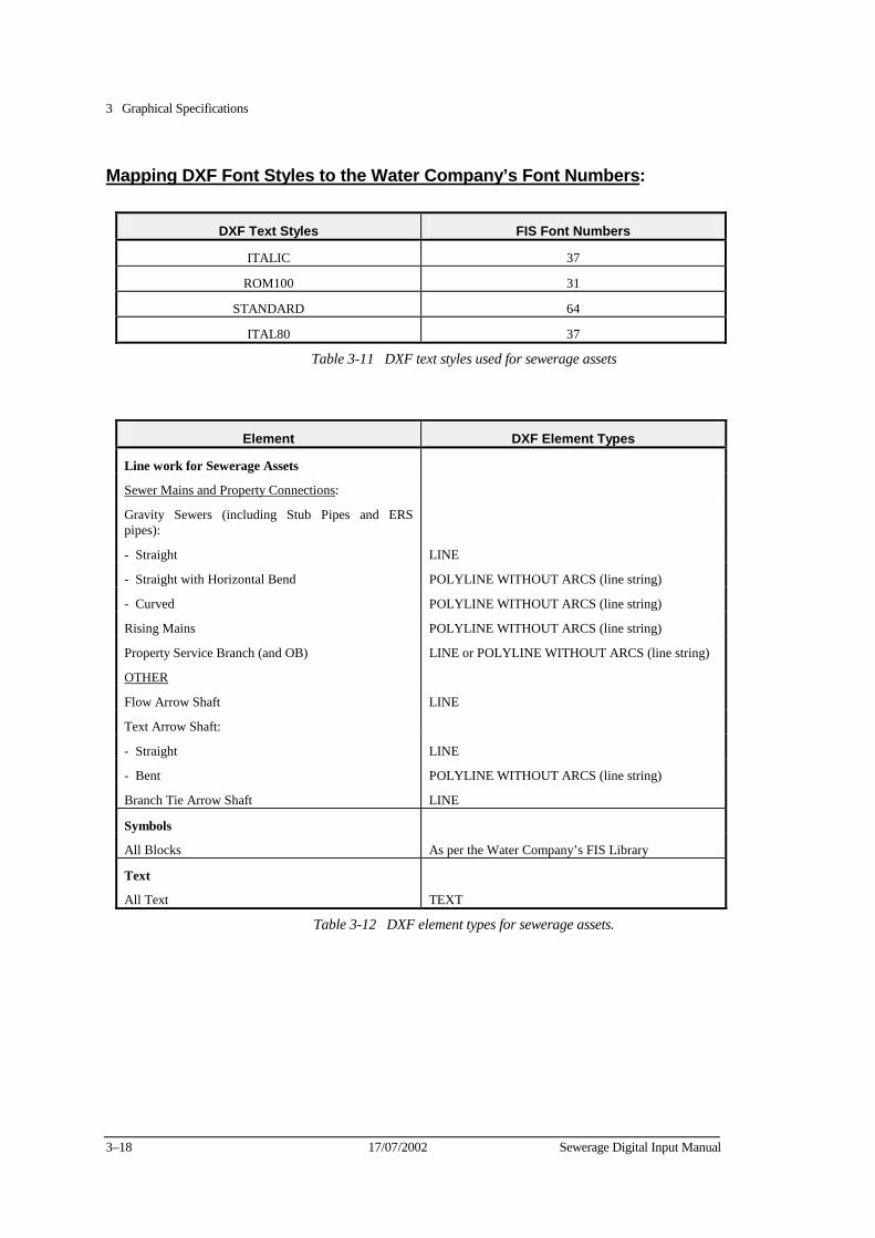
3 Graphical Specifications
3–18 17/07/2002 Sewerage Digital Input Manual
Mapping DXF Font Styles to the Water Company’s Font Numbers:
DXF Text Styles FIS Font Numbers
ITALIC 37
ROM100 31
STANDARD 64
ITAL80 37
Table 3-11 DXF text styles used for sewerage assets
Element DXF Element Types
Line work for Sewerage Assets
Sewer Mains and Property Connections:
Gravity Sewers (including Stub Pipes and ERS pipes):
- Straight LINE
- Straight with Horizontal Bend POLYLINE WITHOUT ARCS (line string)
- Curved POLYLINE WITHOUT ARCS (line string)
Rising Mains POLYLINE WITHOUT ARCS (line string)
Property Service Branch (and OB) LINE or POLYLINE WITHOUT ARCS (line string)
OTHER
Flow Arrow Shaft LINE
Text Arrow Shaft:
- Straight LINE
- Bent POLYLINE WITHOUT ARCS (line string)
Branch Tie Arrow Shaft LINE
Symbols
All Blocks As per the Water Company’s FIS Library
Text
All Text TEXT
Table 3-12 DXF element types for sewerage assets.
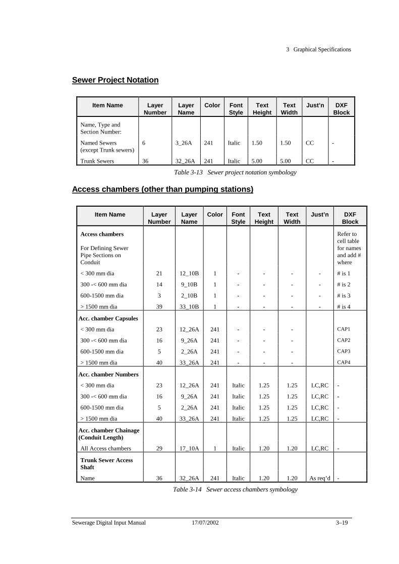
3 Graphical Specifications
Sewerage Digital Input Manual 17/07/2002 3–19
Sewer Project Notation
Item Name Layer Number
Layer Name
Color FontStyle
Text Height
Text Width
Just’n DXF Block
Name, Type and Section Number:
Named Sewers (except Trunk sewers)
6 3_26A 241 Italic 1.50 1.50 CC -
Trunk Sewers 36 32_26A 241 Italic 5.00 5.00 CC -
Table 3-13 Sewer project notation symbology
Access chambers (other than pumping stations)
Item Name Layer Number
LayerName
Color FontStyle
Text Height
Text Width
Just’n DXF Block
Access chambers For Defining Sewer Pipe Sections on Conduit
Refer to cell table for names and add # where
< 300 mm dia 21 12_10B 1 - - - - # is 1
300 -< 600 mm dia 14 9_10B 1 - - - - # is 2
600-1500 mm dia 3 2_10B 1 - - - - # is 3
> 1500 mm dia 39 33_10B 1 - - - - # is 4
Acc. chamber Capsules
< 300 mm dia 23 12_26A 241 - - - CAP1
300 -< 600 mm dia 16 9_26A 241 - - - CAP2
600-1500 mm dia 5 2_26A 241 - - - CAP3
> 1500 mm dia 40 33_26A 241 - - - CAP4
Acc. chamber Numbers
< 300 mm dia 23 12_26A 241 Italic 1.25 1.25 LC,RC -
300 -< 600 mm dia 16 9_26A 241 Italic 1.25 1.25 LC,RC -
600-1500 mm dia 5 2_26A 241 Italic 1.25 1.25 LC,RC -
> 1500 mm dia 40 33_26A 241 Italic 1.25 1.25 LC,RC -
Acc. chamber Chainage (Conduit Length)
All Access chambers 29 17_10A 1 Italic 1.20 1.20 LC,RC -
Trunk Sewer Access Shaft
Name 36 32_26A 241 Italic 1.20 1.20 As req’d -
Table 3-14 Sewer access chambers symbology
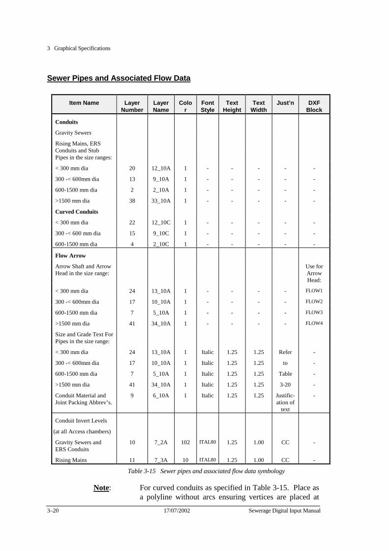
3 Graphical Specifications
3–20 17/07/2002 Sewerage Digital Input Manual
Sewer Pipes and Associated Flow Data
Item Name Layer Number
LayerName
Color
FontStyle
Text Height
Text Width
Just’n DXF Block
Conduits
Gravity Sewers
Rising Mains, ERS Conduits and Stub Pipes in the size ranges:
< 300 mm dia 20 12_10A 1 - - - - -
300 -< 600mm dia 13 9_10A 1 - - - - -
600-1500 mm dia 2 2_10A 1 - - - - -
>1500 mm dia 38 33_10A 1 - - - - -
Curved Conduits
< 300 mm dia 22 12_10C 1 - - - - -
300 -< 600 mm dia 15 9_10C 1 - - - - -
600-1500 mm dia 4 2_10C 1 - - - - -
Flow Arrow
Arrow Shaft and Arrow Head in the size range:
Use for Arrow Head:
< 300 mm dia 24 13_10A 1 - - - - FLOW1
300 -< 600mm dia 17 10_10A 1 - - - - FLOW2
600-1500 mm dia 7 5_10A 1 - - - - FLOW3
>1500 mm dia 41 34_10A 1 - - - - FLOW4
Size and Grade Text For Pipes in the size range:
< 300 mm dia 24 13_10A 1 Italic 1.25 1.25 Refer -
300 -< 600mm dia 17 10_10A 1 Italic 1.25 1.25 to -
600-1500 mm dia 7 5_10A 1 Italic 1.25 1.25 Table -
>1500 mm dia 41 34_10A 1 Italic 1.25 1.25 3-20 -
Conduit Material and Joint Packing Abbrev’s.
9 6_10A 1 Italic 1.25 1.25 Justific-ation of
text
-
Conduit Invert Levels
(at all Access chambers)
Gravity Sewers and ERS Conduits
10 7_2A 102 ITAL80 1.25 1.00 CC -
Rising Mains 11 7_3A 10 ITAL80 1.25 1.00 CC -
Table 3-15 Sewer pipes and associated flow data symbology
Note: For curved conduits as specified in Table 3-15. Place as a polyline without arcs ensuring vertices are placed at
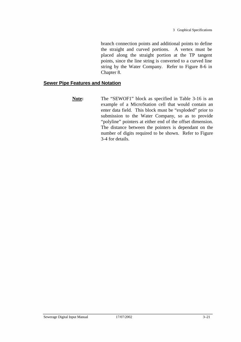
3 Graphical Specifications
Sewerage Digital Input Manual 17/07/2002 3–21
branch connection points and additional points to define the straight and curved portions. A vertex must be placed along the straight portion at the TP tangent points, since the line string is converted to a curved line string by the Water Company. Refer to Figure 8-6 in Chapter 8.
Sewer Pipe Features and Notation
Note: The “SEWOF1” block as specified in Table 3-16 is an example of a MicroStation cell that would contain an enter data field. This block must be “exploded” prior to submission to the Water Company, so as to provide “polyline” pointers at either end of the offset dimension. The distance between the pointers is dependant on the number of digits required to be shown. Refer to Figure 3-4 for details.
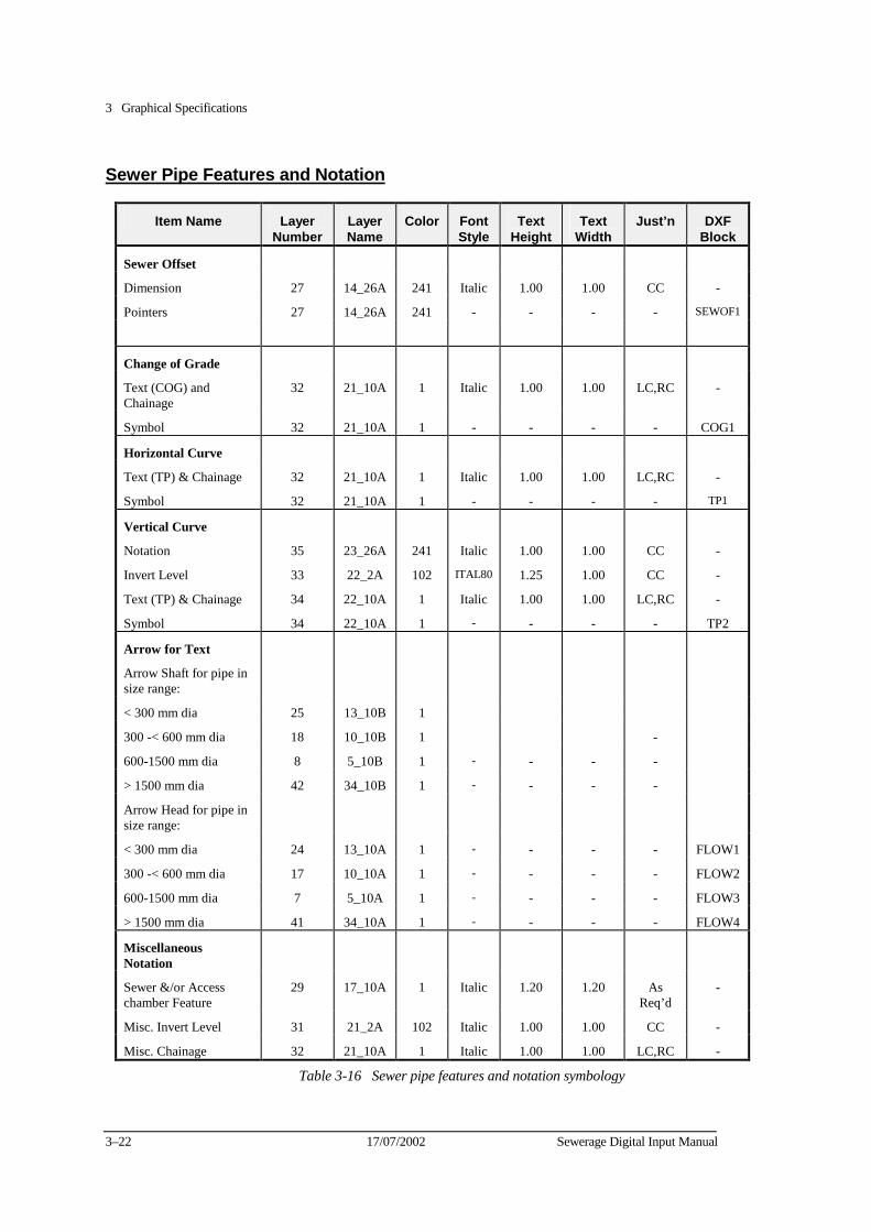
3 Graphical Specifications
3–22 17/07/2002 Sewerage Digital Input Manual
Sewer Pipe Features and Notation
Item Name Layer Number
Layer Name
Color FontStyle
Text Height
Text Width
Just’n DXF Block
Sewer Offset
Dimension 27 14_26A 241 Italic 1.00 1.00 CC -
Pointers 27 14_26A 241 - - - - SEWOF1
Change of Grade
Text (COG) and Chainage
32 21_10A 1 Italic 1.00 1.00 LC,RC -
Symbol 32 21_10A 1 - - - - COG1
Horizontal Curve
Text (TP) & Chainage 32 21_10A 1 Italic 1.00 1.00 LC,RC -
Symbol 32 21_10A 1 - - - - TP1
Vertical Curve
Notation 35 23_26A 241 Italic 1.00 1.00 CC -
Invert Level 33 22_2A 102 ITAL80 1.25 1.00 CC -
Text (TP) & Chainage 34 22_10A 1 Italic 1.00 1.00 LC,RC -
Symbol 34 22_10A 1 - - - - TP2
Arrow for Text
Arrow Shaft for pipe in size range:
< 300 mm dia 25 13_10B 1
300 -< 600 mm dia 18 10_10B 1 -
600-1500 mm dia 8 5_10B 1 - - - -
> 1500 mm dia 42 34_10B 1 - - - -
Arrow Head for pipe in size range:
< 300 mm dia 24 13_10A 1 - - - - FLOW1
300 -< 600 mm dia 17 10_10A 1 - - - - FLOW2
600-1500 mm dia 7 5_10A 1 - - - - FLOW3
> 1500 mm dia 41 34_10A 1 - - - - FLOW4
Miscellaneous Notation
Sewer &/or Access chamber Feature
29 17_10A 1 Italic 1.20 1.20 As Req’d
-
Misc. Invert Level 31 21_2A 102 Italic 1.00 1.00 CC -
Misc. Chainage 32 21_10A 1 Italic 1.00 1.00 LC,RC -
Table 3-16 Sewer pipe features and notation symbology
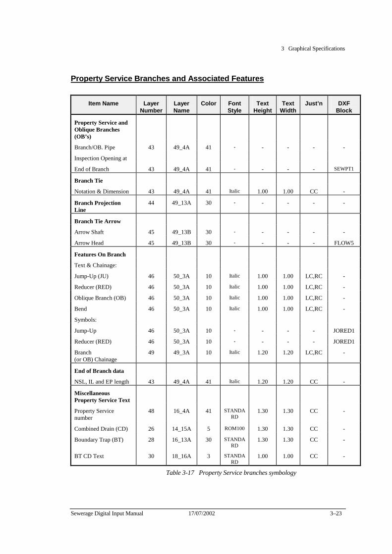
3 Graphical Specifications
Sewerage Digital Input Manual 17/07/2002 3–23
Property Service Branches and Associated Features
Item Name Layer Number
Layer Name
Color Font Style
Text Height
Text Width
Just’n DXF Block
Property Service and Oblique Branches (OB’s)
Branch/OB. Pipe 43 49_4A 41 - - - - -
Inspection Opening at
End of Branch 43 49_4A 41 - - - - SEWPT1
Branch Tie
Notation & Dimension 43 49_4A 41 Italic 1.00 1.00 CC -
Branch Projection Line
44 49_13A 30 - - - - -
Branch Tie Arrow
Arrow Shaft 45 49_13B 30 - - - - -
Arrow Head 45 49_13B 30 - - - - FLOW5
Features On Branch
Text & Chainage:
Jump-Up (JU) 46 50_3A 10 Italic 1.00 1.00 LC,RC -
Reducer (RED) 46 50_3A 10 Italic 1.00 1.00 LC,RC -
Oblique Branch (OB) 46 50_3A 10 Italic 1.00 1.00 LC,RC -
Bend 46 50_3A 10 Italic 1.00 1.00 LC,RC -
Symbols:
Jump-Up 46 50_3A 10 - - - - JORED1
Reducer (RED) 46 50_3A 10 - - - - JORED1
Branch (or OB) Chainage
49 49_3A 10 Italic 1.20 1.20 LC,RC -
End of Branch data
NSL, IL and EP length 43 49_4A 41 Italic 1.20 1.20 CC -
Miscellaneous Property Service Text
Property Service number
48 16_4A 41 STANDARD
1.30 1.30 CC -
Combined Drain (CD) 26 14_15A 5 ROM100 1.30 1.30 CC -
Boundary Trap (BT) 28 16_13A 30 STANDARD
1.30 1.30 CC -
BT CD Text 30 18_16A 3 STANDARD
1.00 1.00 CC -
Table 3-17 Property Service branches symbology
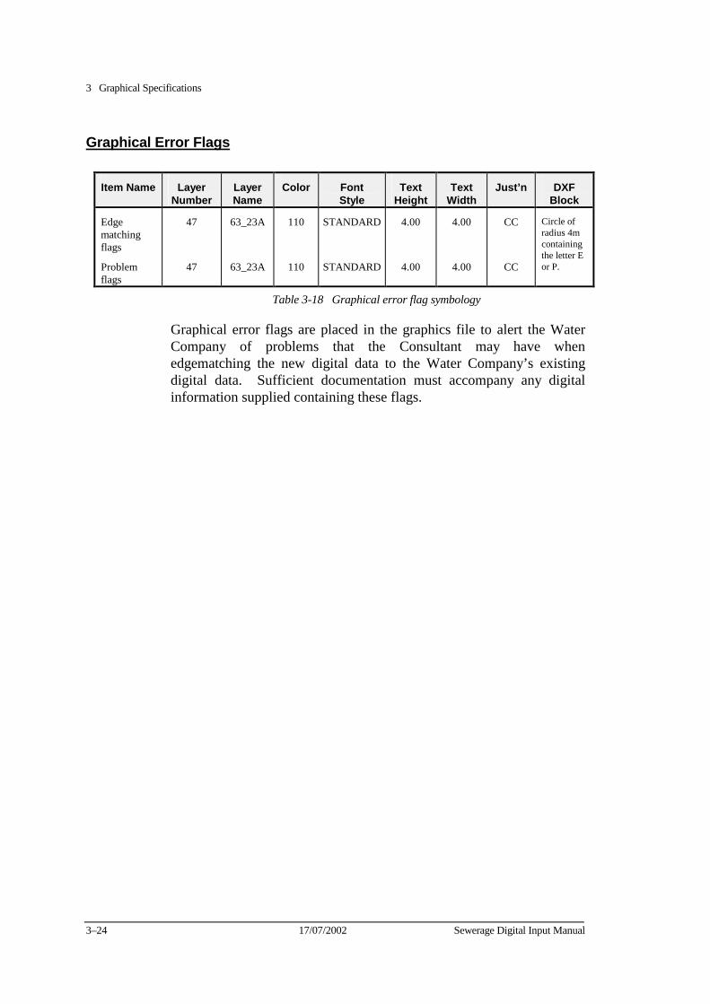
3 Graphical Specifications
3–24 17/07/2002 Sewerage Digital Input Manual
Graphical Error Flags
Item Name Layer Number
Layer Name
Color Font Style
Text Height
Text Width
Just’n DXF Block
Edge matching flags
Problem flags
47
47
63_23A
63_23A
110
110
STANDARD
STANDARD
4.00
4.00
4.00
4.00
CC
CC
Circle of radius 4m containing the letter E or P.
Table 3-18 Graphical error flag symbology
Graphical error flags are placed in the graphics file to alert the Water Company of problems that the Consultant may have when edgematching the new digital data to the Water Company’s existing digital data. Sufficient documentation must accompany any digital information supplied containing these flags.
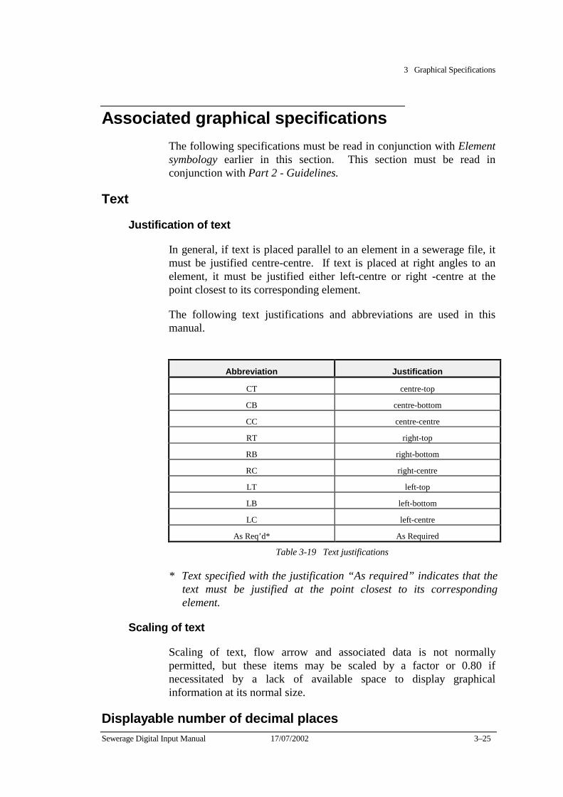
3 Graphical Specifications
Sewerage Digital Input Manual 17/07/2002 3–25
Associated graphical specifications The following specifications must be read in conjunction with Element symbology earlier in this section. This section must be read in conjunction with Part 2 - Guidelines.
Text
Justification of text
In general, if text is placed parallel to an element in a sewerage file, it must be justified centre-centre. If text is placed at right angles to an element, it must be justified either left-centre or right -centre at the point closest to its corresponding element.
The following text justifications and abbreviations are used in this manual.
Abbreviation Justification
CT centre-top
CB centre-bottom
CC centre-centre
RT right-top
RB right-bottom
RC right-centre
LT left-top
LB left-bottom
LC left-centre
As Req’d* As Required
Table 3-19 Text justifications
* Text specified with the justification “As required” indicates that the text must be justified at the point closest to its corresponding element.
Scaling of text
Scaling of text, flow arrow and associated data is not normally permitted, but these items may be scaled by a factor or 0.80 if necessitated by a lack of available space to display graphical information at its normal size.
Displayable number of decimal places
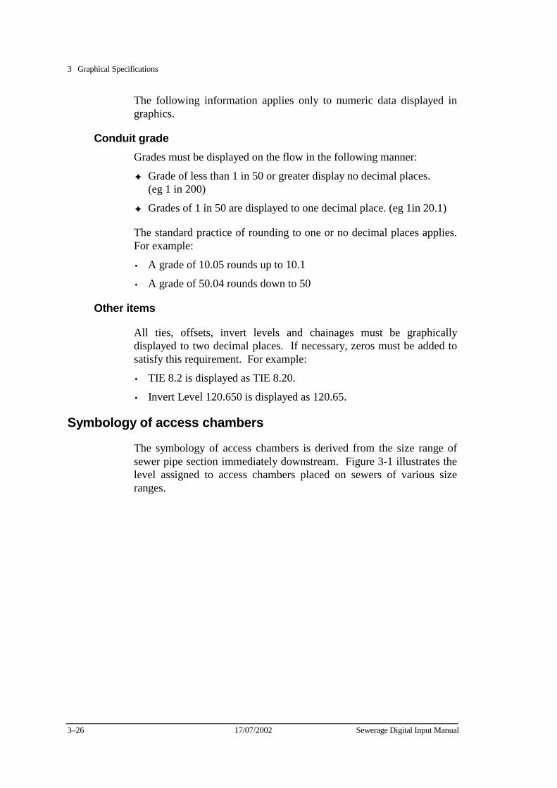
3 Graphical Specifications
3–26 17/07/2002 Sewerage Digital Input Manual
The following information applies only to numeric data displayed in graphics.
Conduit grade Grades must be displayed on the flow in the following manner:
✦ Grade of less than 1 in 50 or greater display no decimal places. (eg 1 in 200)
✦ Grades of 1 in 50 are displayed to one decimal place. (eg 1in 20.1)
The standard practice of rounding to one or no decimal places applies. For example:
• A grade of 10.05 rounds up to 10.1
• A grade of 50.04 rounds down to 50
Other items
All ties, offsets, invert levels and chainages must be graphically displayed to two decimal places. If necessary, zeros must be added to satisfy this requirement. For example:
• TIE 8.2 is displayed as TIE 8.20.
• Invert Level 120.650 is displayed as 120.65.
Symbology of access chambers
The symbology of access chambers is derived from the size range of sewer pipe section immediately downstream. Figure 3-1 illustrates the level assigned to access chambers placed on sewers of various size ranges.
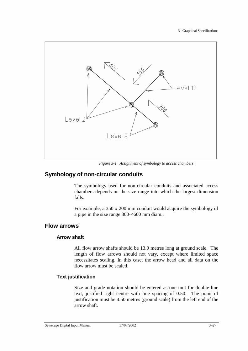
3 Graphical Specifications
Sewerage Digital Input Manual 17/07/2002 3–27
Figure 3-1 Assignment of symbology to access chambers
Symbology of non-circular conduits
The symbology used for non-circular conduits and associated access chambers depends on the size range into which the largest dimension falls.
For example, a 350 x 200 mm conduit would acquire the symbology of a pipe in the size range 300-<600 mm diam..
Flow arrows
Arrow shaft
All flow arrow shafts should be 13.0 metres long at ground scale. The length of flow arrows should not vary, except where limited space necessitates scaling. In this case, the arrow head and all data on the flow arrow must be scaled.
Text justification
Size and grade notation should be entered as one unit for double-line text, justified right centre with line spacing of 0.50. The point of justification must be 4.50 metres (ground scale) from the left end of the arrow shaft.
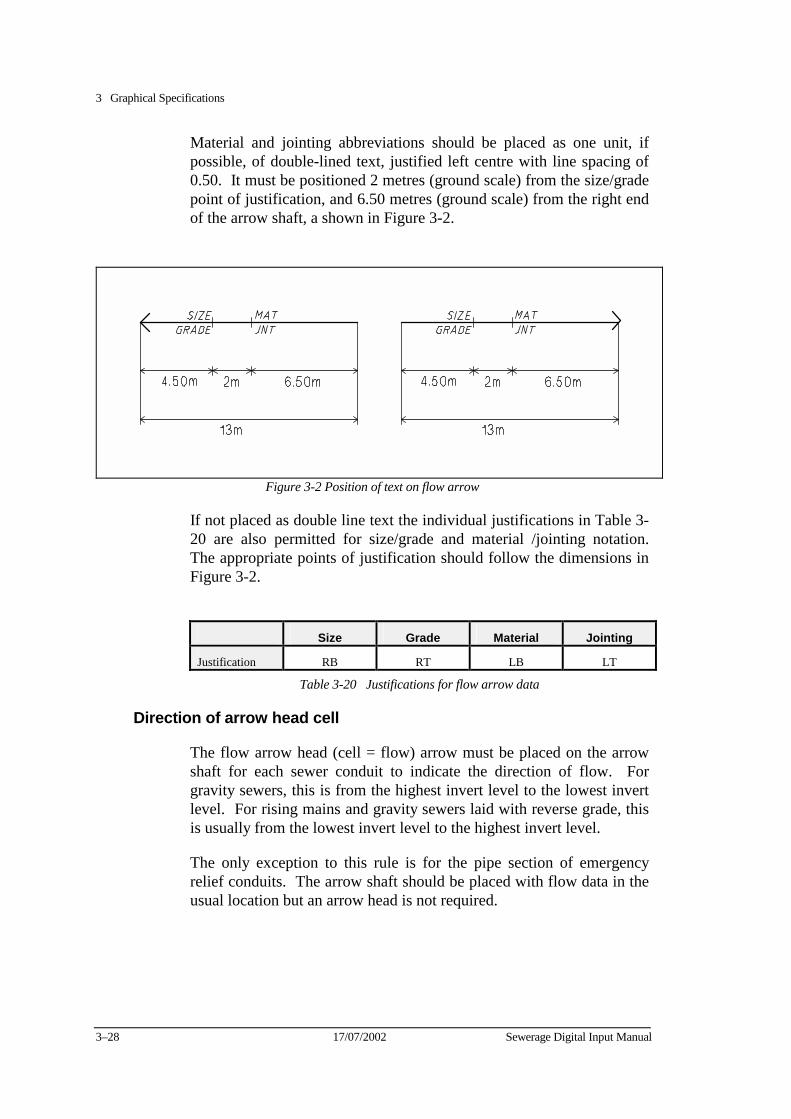
3 Graphical Specifications
3–28 17/07/2002 Sewerage Digital Input Manual
Material and jointing abbreviations should be placed as one unit, if possible, of double-lined text, justified left centre with line spacing of 0.50. It must be positioned 2 metres (ground scale) from the size/grade point of justification, and 6.50 metres (ground scale) from the right end of the arrow shaft, a shown in Figure 3-2.
Figure 3-2 Position of text on flow arrow
If not placed as double line text the individual justifications in Table 3-20 are also permitted for size/grade and material /jointing notation. The appropriate points of justification should follow the dimensions in Figure 3-2.
Size Grade Material Jointing
Justification RB RT LB LT
Table 3-20 Justifications for flow arrow data
Direction of arrow head cell
The flow arrow head (cell = flow) arrow must be placed on the arrow shaft for each sewer conduit to indicate the direction of flow. For gravity sewers, this is from the highest invert level to the lowest invert level. For rising mains and gravity sewers laid with reverse grade, this is usually from the lowest invert level to the highest invert level.
The only exception to this rule is for the pipe section of emergency relief conduits. The arrow shaft should be placed with flow data in the usual location but an arrow head is not required.

3 Graphical Specifications
Sewerage Digital Input Manual 17/07/2002 3–29
Limit of displayable characters
Table 3-21 shows the maximum number of characters to be displayed in each category.
Flow Arrow Notation Maximum Number of Displayed
Characters
Size 4
Grade 4
Material 6
Jointing 6
Table 3-21 Limit of displayable characters
Display of notation derived form code lists
Flow arrow notation must be displayed in graphics on the flow arrow in exactly the manner shown in the respective abbreviated code lists. Variations in abbreviation of flow arrow notation are not acceptable.
For example, the conduit material abbreviation UPVC must displayed on the flow arrow in lieu of the sometimes used abbreviation of PVC.
Calculation of conduit grade
Conduit gradients are usually referred to as grades. They must be calculated using the difference between upstream and downstream invert levels and the conduit length. The following formula is used to calculate grades:
Conduit length (Upstream IL - Downstream IL)
The grade must be displayed as an integer. Grades must not be displayed as percentages or fractions.
Standard offsets of selected sewerage notation
Table 3-22 lists the offsets that should be used as guide to the desired manual placement of data. All offsets are measured, at ground scale, to the point of justification. Refer to the relevant sections of Part 2 - Guidelines for further details on the placement of these items.
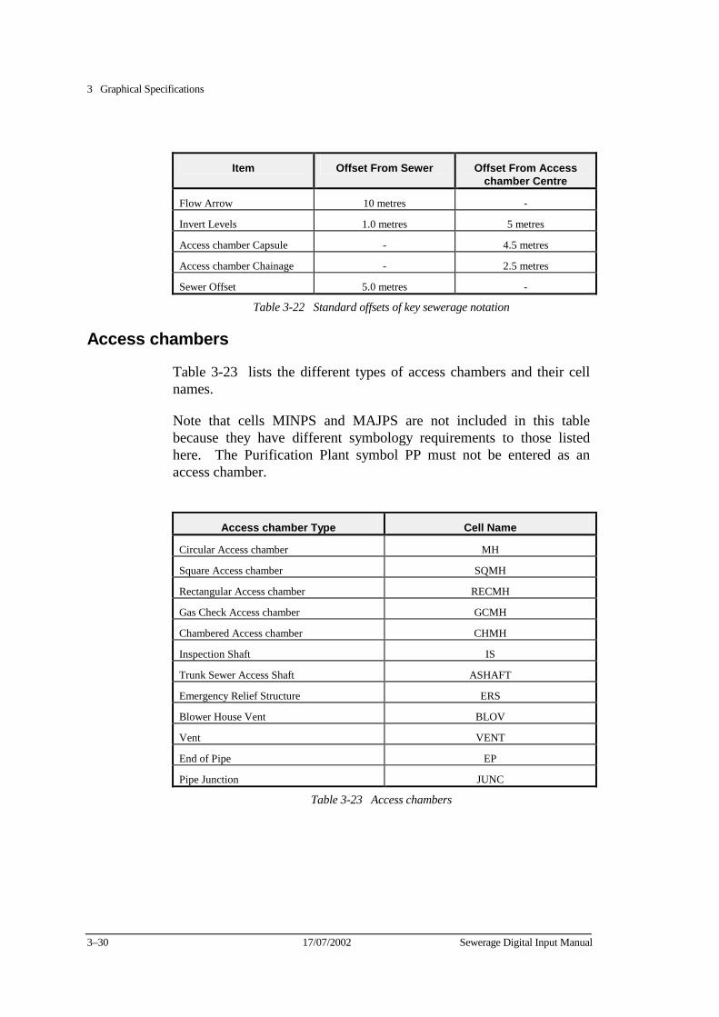
3 Graphical Specifications
3–30 17/07/2002 Sewerage Digital Input Manual
Item Offset From Sewer Offset From Access
chamber Centre
Flow Arrow 10 metres -
Invert Levels 1.0 metres 5 metres
Access chamber Capsule - 4.5 metres
Access chamber Chainage - 2.5 metres
Sewer Offset 5.0 metres -
Table 3-22 Standard offsets of key sewerage notation
Access chambers
Table 3-23 lists the different types of access chambers and their cell names.
Note that cells MINPS and MAJPS are not included in this table because they have different symbology requirements to those listed here. The Purification Plant symbol PP must not be entered as an access chamber.
Access chamber Type Cell Name
Circular Access chamber MH
Square Access chamber� SQMH
Rectangular Access chamber RECMH
Gas Check Access chamber GCMH
Chambered Access chamber CHMH
Inspection Shaft IS
Trunk Sewer Access Shaft ASHAFT
Emergency Relief Structure ERS
Blower House Vent BLOV
Vent VENT
End of Pipe EP
Pipe Junction JUNC
Table 3-23 Access chambers
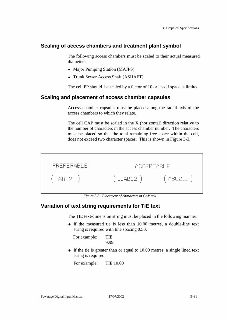
3 Graphical Specifications
Sewerage Digital Input Manual 17/07/2002 3–31
Scaling of access chambers and treatment plant symbol
The following access chambers must be scaled to their actual measured diameters:
✦ Major Pumping Station (MAJPS)
✦ Trunk Sewer Access Shaft (ASHAFT)
The cell PP should be scaled by a factor of 10 or less if space is limited.
Scaling and placement of access chamber capsules
Access chamber capsules must be placed along the radial axis of the access chambers to which they relate.
The cell CAP must be scaled in the X (horizontal) direction relative to the number of characters in the access chamber number. The characters must be placed so that the total remaining free space within the cell, does not exceed two character spaces. This is shown in Figure 3-3.
Figure 3-3 Placement of characters in CAP cell
Variation of text string requirements for TIE text
The TIE text/dimension string must be placed in the following manner:
✦ If the measured tie is less than 10.00 metres, a double-line text string is required with line spacing 0.50.
For example: TIE 9.99
✦ If the tie is greater than or equal to 10.00 metres, a single lined text string is required.
For example: TIE 10.00
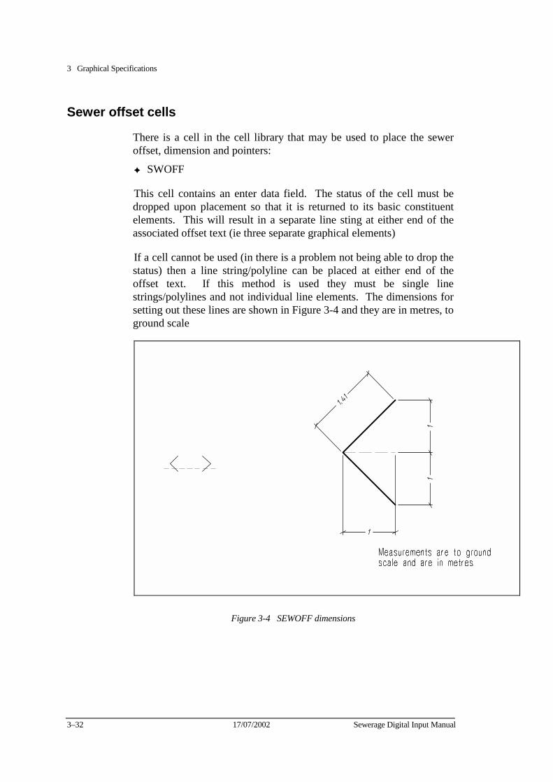
3 Graphical Specifications
3–32 17/07/2002 Sewerage Digital Input Manual
Sewer offset cells
There is a cell in the cell library that may be used to place the sewer offset, dimension and pointers:
✦ SWOFF
This cell contains an enter data field. The status of the cell must be dropped upon placement so that it is returned to its basic constituent elements. This will result in a separate line sting at either end of the associated offset text (ie three separate graphical elements)
If a cell cannot be used (in there is a problem not being able to drop the status) then a line string/polyline can be placed at either end of the offset text. If this method is used they must be single line strings/polylines and not individual line elements. The dimensions for setting out these lines are shown in Figure 3-4 and they are in metres, to ground scale
Figure 3-4 SEWOFF dimensions
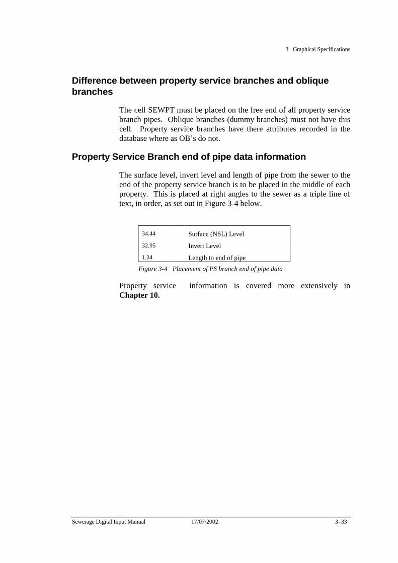
3 Graphical Specifications
Sewerage Digital Input Manual 17/07/2002 3–33
Difference between property service branches and oblique branches
The cell SEWPT must be placed on the free end of all property service branch pipes. Oblique branches (dummy branches) must not have this cell. Property service branches have there attributes recorded in the database where as OB’s do not.
Property Service Branch end of pipe data information
The surface level, invert level and length of pipe from the sewer to the end of the property service branch is to be placed in the middle of each property. This is placed at right angles to the sewer as a triple line of text, in order, as set out in Figure 3-4 below.
34.44 Surface (NSL) Level
32.95 Invert Level
1.34 Length to end of pipe
Figure 3-4 Placement of PS branch end of pipe data
Property service information is covered more extensively in Chapter 10.
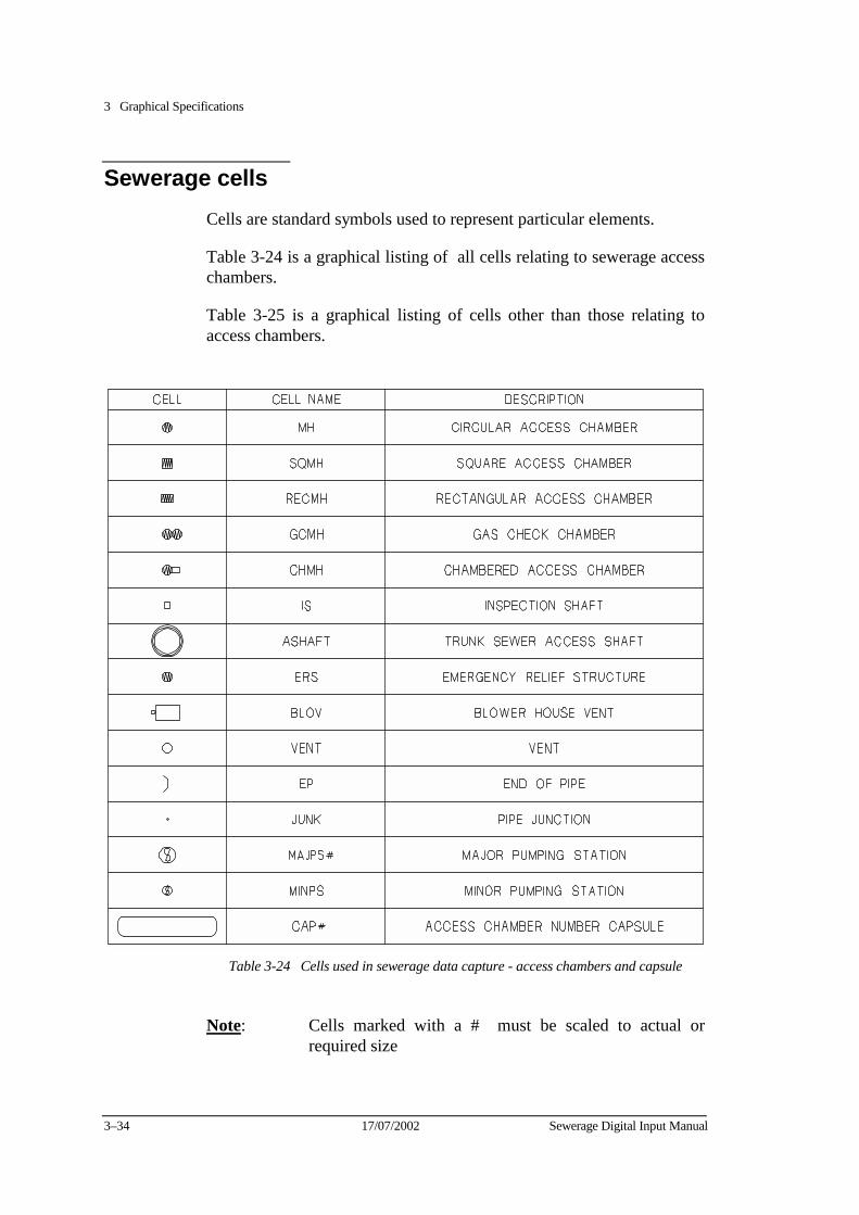
3 Graphical Specifications
3–34 17/07/2002 Sewerage Digital Input Manual
Sewerage cells Cells are standard symbols used to represent particular elements.
Table 3-24 is a graphical listing of all cells relating to sewerage access chambers.
Table 3-25 is a graphical listing of cells other than those relating to access chambers.
Table 3-24 Cells used in sewerage data capture - access chambers and capsule
Note: Cells marked with a # must be scaled to actual or required size
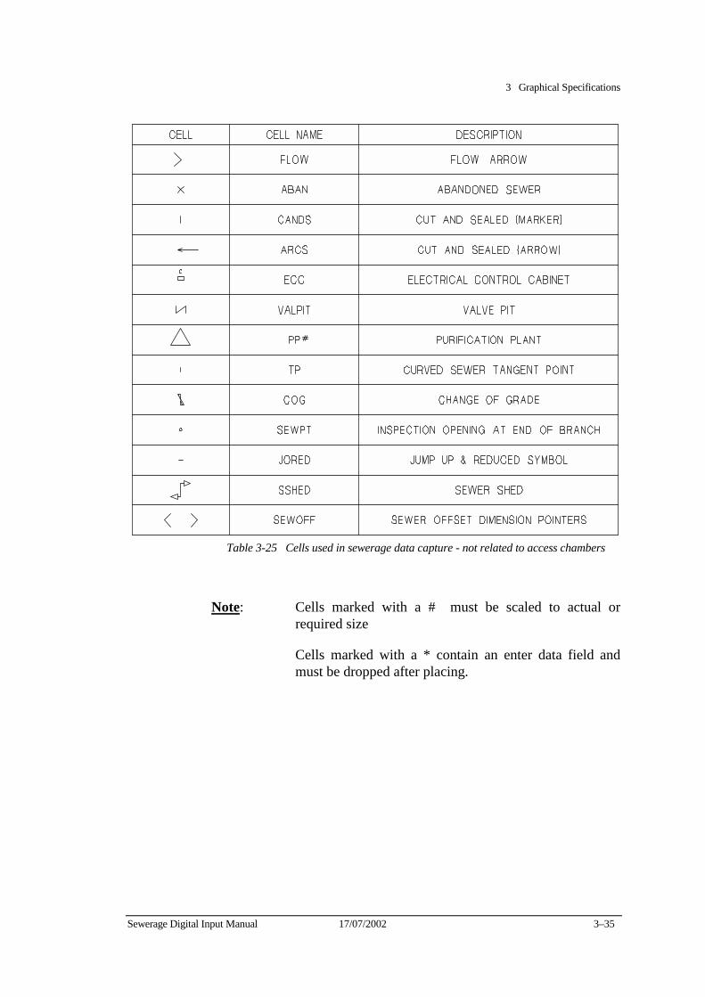
3 Graphical Specifications
Sewerage Digital Input Manual 17/07/2002 3–35
Table 3-25 Cells used in sewerage data capture - not related to access chambers
Note: Cells marked with a # must be scaled to actual or required size
Cells marked with a * contain an enter data field and must be dropped after placing.

3 Graphical Specifications
3–36 17/07/2002 Sewerage Digital Input Manual
Chapter 4 Placement of Data in Graphics Files
This chapter provides guidelines for the placement of pipework, access chambers and associated features and notation in sewerage graphics files.
Placement of data with regard to file boundaries
The geographical file boundaries of the Water Company are defined in the municipal index files. Sewer pipes, access chambers and associated data and notation must be placed with regard to the file boundaries, as shown in Figure 4-1.
Sewers which cross file boundaries: • must not be broken at the file boundary. They must be placed as continuous
lines, from access chamber to access chamber across the boundary. • must be stored in the graphics file in which the majority of the sewer pipe
section resides.
Access chambers on sewers which cross file boundaries must be stored in the graphics file in which they are geographically located, except when they terminate the upstream end of a sewer line. These access chambers must be stored in the same graphics file as the sewer pipe section.
Property service branches, invert levels, notation, chainages, flow arrows, etc. must be stored in the same graphics file as the sewer pipe section to which they refer.
Ote: No elements or text must be duplicated when placing data across file
boundaries. Edgematching to existing data
Edgematching is the process of joining new sewer pipe sections to existing graphics data. Edgematching is required when digitising across file boundaries, or when joining to existing data within a file supplied by the Water Company. When edgematching, ensure that: + no elements or text are duplicated, • sewer lines intersect exactly at the centre of access chambers,
sere nwtal input Manual 27/02/95 4-i

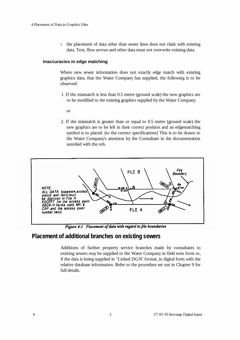
4. 2 27/02/95 Sevvasge Digital kaput
4 Placement of Data in Graphics Files
t the placement of data other than sewer lines does not clash with existing data. Text, flow arrows and other data must not overwrite existing data.
Inaccuracies in edge matching
Where new sewer information does not exactly edge match with existing graphics data, that the Water Company has supplied, the following is to be observed:
1. If the mismatch is less than 0.5 metre (ground scale) the new graphics are
to be modified to the existing graphics supplied by the Water Company.
or
2. If the mismatch is greater than or equal to 0.5 metre (ground scale) the new graphics are to be left in their correct position and an edgematching symbol is to placed. (to the correct specifications) This is to be drawn to the Water Company's attention by the Consultant in the documentation sunnlied with the rob.
Placement of additional branches on existing sewers
Additions of further property service branches made by consultants to existing sewers may be supplied to the Water Company in field note form or, if the data is being supplied in "Linked DGN' format, in digital form with the relative database information. Refer to the procedure set out in Chapter 9 for full details.

4 Placement of Data in Graphics Files
Placement of text and flow data
Text must always be placed so that it does not clash with cadastral information, including:
• title/property boundaries
t easements and associated text
t road boundaries
road names
property lot numbers
street numbers Text placement priorities
These guidelines must be observed when placing text for sewerage conduits and structures.
The following list indicates the order of importance for the placement of each item of text. The priorities must be applied whenever space is limited.
1. Sewer inverts - as close as practical to sewer (above or below) and as near
M.H./I.S. as possible, remaining clear of easements and title lines.
2. Branch & M.H./I.S. chainages - on the opposite side of the sewer to the branch and either side for M.H./I. S. remaining clear of easements and title lines.
3. Flow arrow - above sewer (where possible) at specified offset from sewer, remaining clear of easements, title lines, chainages, etc.
4. Branch information - to be located in approximately the centre of the
property. For large allotments, reserves, etc. locate close to branch.
5. T_ - between branch and relevant title line (where possiible), clear of easements, title lines, chainages, etc.
6. P.S. Numbers - parallel to front boundary, between boundary and lot
number. Sewerage Digital Input Manual 27/02/95 4-3

4 Placement of Data in Graphics Files 7. Sewer offsets - within the property that the sewer is located in (where
possible), clear of easements, title lines, chainages, etc. 8. Access chamber capsules
9. Notation associated with: - treatment plants - named sewers - abandoned
sewers, cut and sealing's - purchased sewers - curved sewers - changes of
grade - oblique branches, jump ups, bends - boundary traps, combined drains Placement of text in areas of limited space
Text must not clash with associated sewerage data. Where space is limited, and after referring to the priorities listed in the previous section, one ore more of the following alternatives may be used: • The invert levels of a sewer pipe section can be grouped with the associated
flow arrow. The grouped data should then be placed above the sewer pipe section or in close proximity to pipe section if space is limited. Data can be placed outside the information boundary. The information boundaries of a sewer pipe section are defined by an imaginary line perpendicular to the sewer pipe section and projected from each access chamber.
* Use text arrows to associate data with the appropriate pipe section. • Text and flow arrows may be scaled (as a last resort) down by a factor of 0.8.
4-4 27/02/95 Sevaage Digital Input Manual
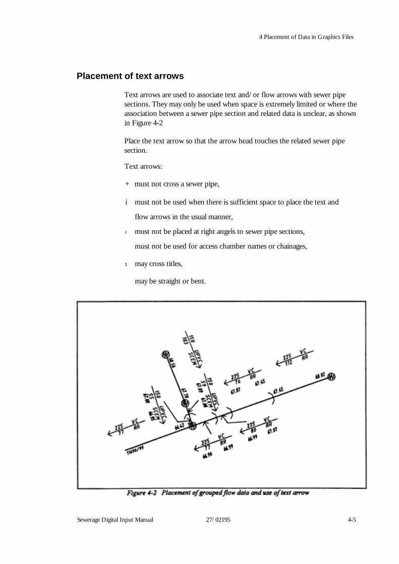
4 Placement of Data in Graphics Files
Placement of text arrows
Text arrows are used to associate text and/or flow arrows with sewer pipe sections. They may only be used when space is extremely limited or where the association between a sewer pipe section and related data is unclear, as shown in Figure 4-2 Place the text arrow so that the arrow head touches the related sewer pipe section.
Text arrows:
+ must not cross a sewer pipe,
i must not be used when there is sufficient space to place the text and
flow arrows in the usual manner,
f must not be placed at right angels to sewer pipe sections,
must not be used for access chamber names or chainages,
t may cross titles,
may be straight or bent.
Sewerage Digital Input Manual 27/02195 4-5
Chapter 5 Sewerage Treatment Plants
This chapter covers the database and graphical requirements for the input of sewerage treatment plants. In this document the terms "sewerage treatment plant" and "sewerage purification plant" refer to the same entity.
Database
Sewerage Treatment Plants (entity 301) are located at the top of the database hierarchy. Entity 301 owns all other entities in the database either directly or indirectly.
Sewerage treatment plants have no graphical elements that are linked to the database. All elements within the treatment plant complex downstream of the entry access chambers) are graphical representations only.
Graphics
Name, number and type
The name of the treatment plant is determined from the Regional Asset areas and will be provided to consultants upon request and should be displayed in graphics as listed in Code List 329.
The name should be placed in upper case at an active angle of zero degrees (horizontally).
The number of the treatment plant is determined from Code List 330.
The type of plant is determined from the letter prefix of the number, that is:
M Major Purification Plant
R Regional Purification Plant
N Neighbourhood Purification Plant
Note: Designate the plant as a purification plant unless specified as a
treatment plant in the code lists. Sewerage Digital Input Manual 27/02/95 5-1
x
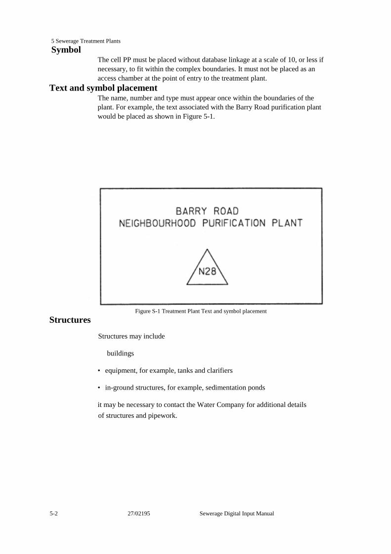
5 Sewerage Treatment Plants Symbol
The cell PP must be placed without database linkage at a scale of 10, or less if necessary, to fit within the complex boundaries. It must not be placed as an access chamber at the point of entry to the treatment plant.
Text and symbol placement The name, number and type must appear once within the boundaries of the plant. For example, the text associated with the Barry Road purification plant would be placed as shown in Figure 5-1.
Figure S-1 Treatment Plant Text and symbol placement Structures
Structures may include
buildings
• equipment, for example, tanks and clarifiers
• in-ground structures, for example, sedimentation ponds
it may be necessary to contact the Water Company for additional details of structures and pipework.
5-2 27/02195 Sewerage Digital Input Manual
5 Sewerage Treatment Plants
Internal pipework and access chambers Internal pipework refers to all pipes downstream of the access chamber at the point of entry to the complex. This includes the outfall pipe to the outlet drain. Standard cells may be placed without database attributes to represent pipeline structures within the plant. The cells should be scaled as necessary. Lines, line strings, arcs, ellipses and other element types may also be used.
Labels, notation and pipeline text Treatment plant labels include notation which identifies buildings, equipment and
other in-ground structures. Treatment plant pipeline notation includes: t pipe size
f grade
material and jointing
• pipe purpose, for example, "Effluent Line" Flow arrows and associated data should only be included when there is sufficient information to determine the direction of flow. When placing flow arrows particular attention should be given to pipes designated as rising mains.
Any available data (for example, pipe size or material) should be placed along the pipe, either above or below.
Invert levels of internal pipework must be input as miscellaneous invert levels.
Numbering of access chambers at point of entry to treatment plants Refer to Numbering access chamber at point of entry to treatment plants in Chapter 7 (Access chambers)
Sewerage Digital Input Manual 27/02/95 5-3
Chapter 6 Sewer Projects
This chapter describes the database and graphical requirements for the input of sewer projects.
Database
Sewer projects have no graphical element that is linked to the database. Ownership of sewer projects
Sewer Projects (entity 303) are owned by the Sewerage Treatment Plant entity (entity 301). Together these entities own all other entities in the sewerage database, either directly or indirectly.
The database entry of sewer projects must conform to the following guidelines:
+ The sewer name (303.10) for a named sewer must be a legitimate entry from
Code List 301.
+ The section number (303.14) for a named sewer must be entered as supplied by the Authority or as the default value of "I".
+ The reticulation area number (303.15) must be prefixed with "RA". For
example, RA1234 would apply to reticulation area number 1234.
+ Sewer renewal numbers for sewer replacements, must also be entered as attribute 303.15, but must be prefixed with the text "SR".
+ The reticulation extension number (303.16) must not be prefixed by any text.
Enter the two numbers separated by a slash. For example, 122/90 would apply i l i i b 122/90
Sewerage Digital Input Mamsl 27/02/95 6-1
6 Sewer Projects
Ownership of sewer projects divided by treatment plant catchment boundaries
Due to the structure of the database, sewer projects can only be owned by a single treatment plant. In rare cases, however, a reticulation area or reticulation extension may straddle a treatment plant catchment boundary. In these cases, the reticulation area or extension project must be divided into the appropriate number of sections, as follows: Determine which is the smaller portion of the project and assign it the suffix "*" in the database. For example, if 123/90 flows to two treatment plants, the smaller portion of the project is assigned the reticulation extension number 123/90*, while the larger portion remains as 123/90. In the rare case of a named sewer that outlets to multiple treatment plants (eg. via a diversion), the project can be entered in the database by adding a suffix "*" to one of section numbers, for example, 1 *.
Named sewers Named sewers, as detailed in Code List 301, are titled as trunk, main, branch, relieving or intercepting sewers. Consequently, they generally have pipe sizes 300 mm or greater. Note: Named sewers with a pipe size of less than 300 mm diem. should be
entered in the usual manner. The graphic symbology of these sewers is assigned on the basis of pipe size.
A section number is usually assigned to named sewers as either a number or a number and a letter. This number is obtained from the Water Company.
If more than one section of a named sewer is constructed as part of a single project, include both section numbers in the database. For example, Section 3 and 4 would be entered as " 3&4".
Reticulation sewers
Reticulation sewers are pipes of less than 300 mm diem., usually 150 mm or 225 mm. Smaller diem. pipes that are functioning as part of sewerage system (usually with an access chamber at the upstream end) are also considered to be reticulation sewers.
Reticulation extension sewer projects must only contain reticulation sewers.
6-2 Z7rov9s atat imm Manual

6 Sewer Projects
Mixed sewer projects It is common for a project to consist of both a named sewer and either a reticulation area or extension. In these cases individual sewers must be assigned to the appropriate project. Assignment is generally based on pipe size: + All pipes 300 mm diem. and above are assigned to the named sewer project. + All pipes less than 300 mm diem. are assigned to either the reticulation area
or reticulation extension project. For example, if BANKSIA STREET BRANCH SEWER SECTION 5 is
constructed as part of RE123/90 then all sewers 300mm diameter and greater must be assigned ownership of the sewer project "Banksia Street Branch Sewer Section 5". All sewers less than 300mm diameter will be owned by reticulation extension 123/90.
For "linked" .DGN jobs all can be included in one batch of data. For "unlinked" .DGN and .DXF jobs the different projects must be supplied in separate batches, one per project.
Named sewers and section number + All sewers of 300 mm diem. and greater must be named. If a name cannot
be determined from plans or field notes, contact the Water Company for assistance.
+ Name sewers must not be assigned the reticulation area or extension number of reticulation sewers constructed as part of the same works.
+ If a named sewer has not been allocated a section number, the section number (303.14) must be entered as 1. Do not enter as 0 or a blank. In these cases do not include the section number in graphics.
+ Any confusion about the above can be clarified by the Water Company.
Reticulation sewers
All sewers less than 300 mm diem. must be assigned a reticulation area or extension number. If a number cannot be determined, contact the Water Company for assistance.
Sevvetage Digital Input Manual 27/02/95 6-3


6 Sewer Projects
Graphics
The following standards apply when inputting sewer project notation.
Placement of named sewer notation
Sewer names and section numbers must be placed in the following manner:
Notation should, where possible:
- be placed above and parallel to the sewer line with individual text
strings for each word,
- be evenly spaced over a maximum distance of 500 metres, as shown in Figure 6-1.
- graphically define the extent of each portion of sewer assigned to each
section number.
- be placed at least once on each portion of sewer that has been assigned a different section number. That is, the entire name must be repeated with each new section number,
- be placed at least once per graphics file, where space permits,
- be placed in accordance with standard drafting practice (ie
-orientation of text to be read from the bottom of a plan).
6-a 27/02/96 Sewerage Digital Input Manual
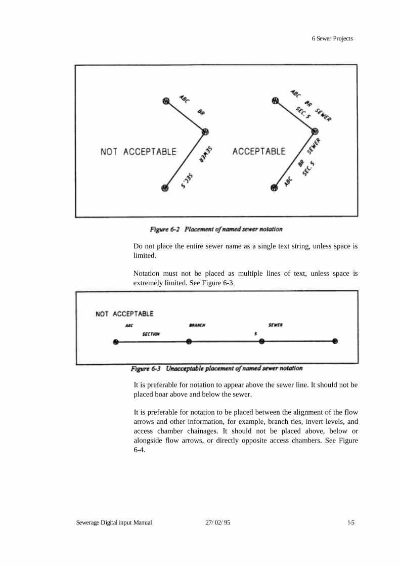
6 Sewer Projects
Sewerage Digital input Manual 27/02/95 !-5
Do not place the entire sewer name as a single text string, unless space is limited. Notation must not be placed as multiple lines of text, unless space is extremely limited. See Figure 6-3
It is preferable for notation to appear above the sewer line. It should not be placed boar above and below the sewer. It is preferable for notation to be placed between the alignment of the flow arrows and other information, for example, branch ties, invert levels, and access chamber chainages. It should not be placed above, below or alongside flow arrows, or directly opposite access chambers. See Figure 6-4.
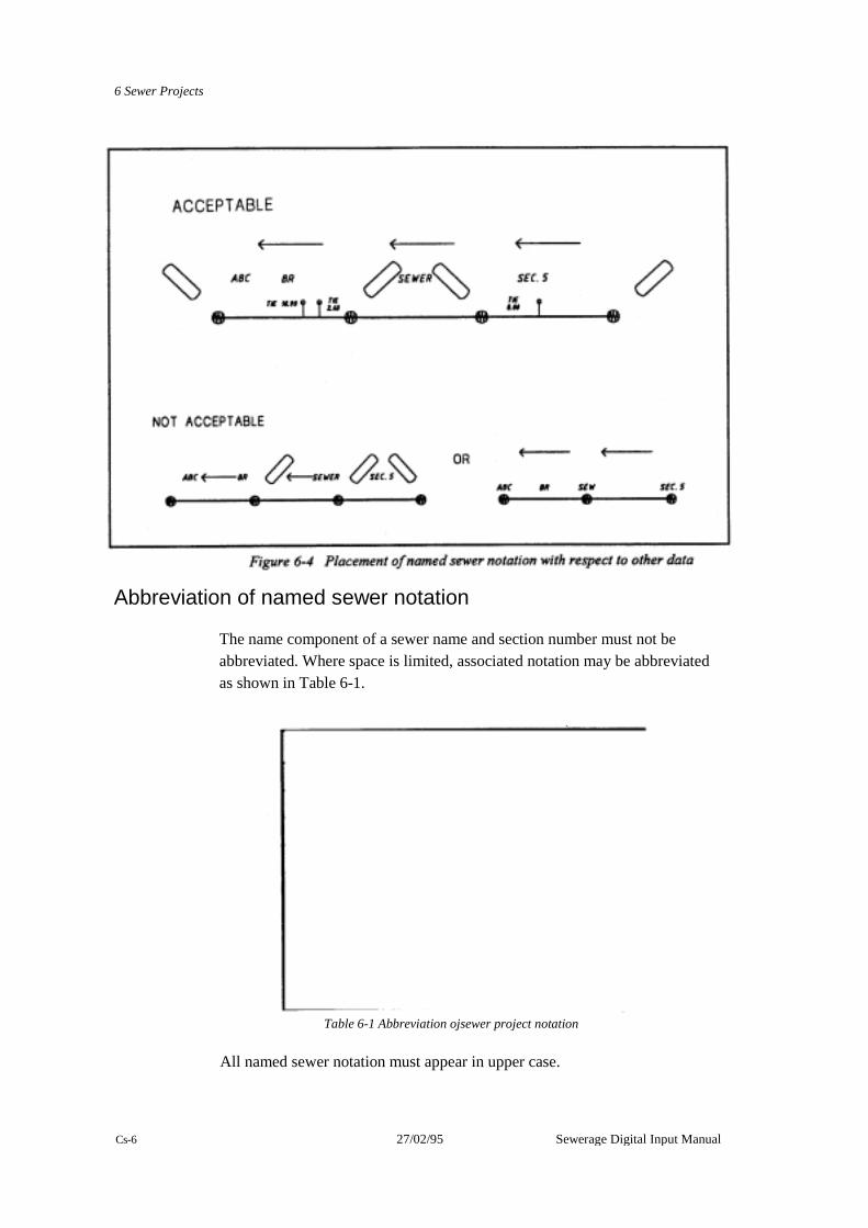
6 Sewer Projects
Table 6-1 Abbreviation ojsewer project notation
All named sewer notation must appear in upper case. Cs-6 27/02/95 Sewerage Digital Input Manual
Abbreviation of named sewer notation
The name component of a sewer name and section number must not be abbreviated. Where space is limited, associated notation may be abbreviated as shown in Table 6-1.

6 Sewer Projects
t If the named sewer does not have an assigned section number, do not
include the section notation. v Road types associated with named sewers may be abbreviated using
standard abbreviations as set out in the Code List 104. For example, the abbreviation for ROAD is RD
Sewerage Digital Input Manual 27/02/95 6-7
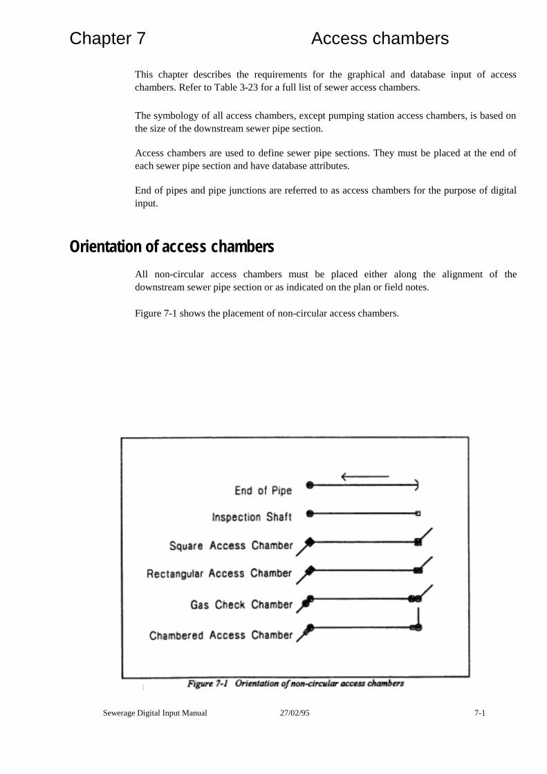
Chapter 7 Access chambers
This chapter describes the requirements for the graphical and database input of access chambers. Refer to Table 3-23 for a full list of sewer access chambers.
The symbology of all access chambers, except pumping station access chambers, is based on the size of the downstream sewer pipe section.
Access chambers are used to define sewer pipe sections. They must be placed at the end of each sewer pipe section and have database attributes.
End of pipes and pipe junctions are referred to as access chambers for the purpose of digital input.
Orientation of access chambers
All non-circular access chambers must be placed either along the alignment of the downstream sewer pipe section or as indicated on the plan or field notes.
Figure 7-1 shows the placement of non-circular access chambers.
Sewerage Digital Input Manual 27/02/95 7-1
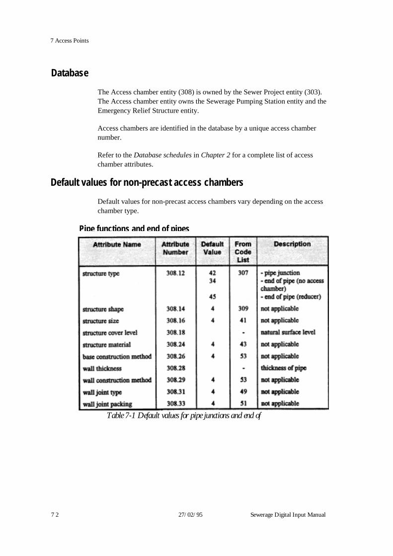
7 Access Points
Database
The Access chamber entity (308) is owned by the Sewer Project entity (303). The Access chamber entity owns the Sewerage Pumping Station entity and the Emergency Relief Structure entity.
Access chambers are identified in the database by a unique access chamber number.
Refer to the Database schedules in Chapter 2 for a complete list of access chamber attributes.
Default values for non-precast access chambers
Default values for non-precast access chambers vary depending on the access chamber type.
Pipe functions and end of pipes
Table 7-1 Default values for pipe junctions and end of
7 2 27/02/95 Sewerage Digital Input Manual

7 Access Points Inspection shafts
Attribute Name Attribute Default From Description Number Value ,Code :List structure type 308.12 33 307 - at end of pipe 29 - over straight through pipe structure shape 308.14 6 309 circular structure size 308.16 41 same as pipe diameter structure cover level 308.18 - as measured in field structure material 308.24 43 as per downstream pipe base construction method 308.26 4 53 not applicable wall thickness 308.28 - thickness of pipe wall construction method 308.29 4 53 not applicable wall joint type 308.31 4 59 not applicable wall joint packing 308.33 4 51 not applicable Table 7-2 Default values for inspection shays
Sewerage Digital Input Manual 27/02195 7-3
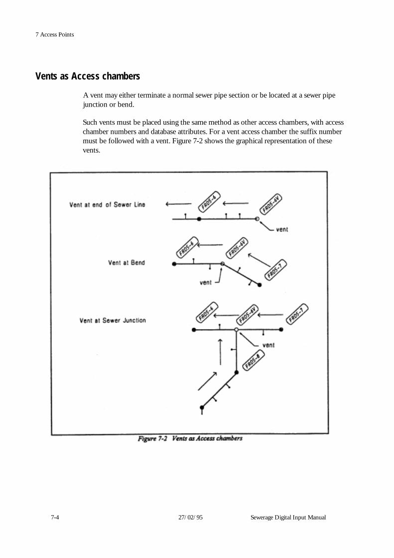
7-4 27/02/95 Sewerage Digital Input Manual
7 Access Points
Vents as Access chambers
A vent may either terminate a normal sewer pipe section or be located at a sewer pipe junction or bend.
Such vents must be placed using the same method as other access chambers, with access chamber numbers and database attributes. For a vent access chamber the suffix number must be followed with a vent. Figure 7-2 shows the graphical representation of these vents.
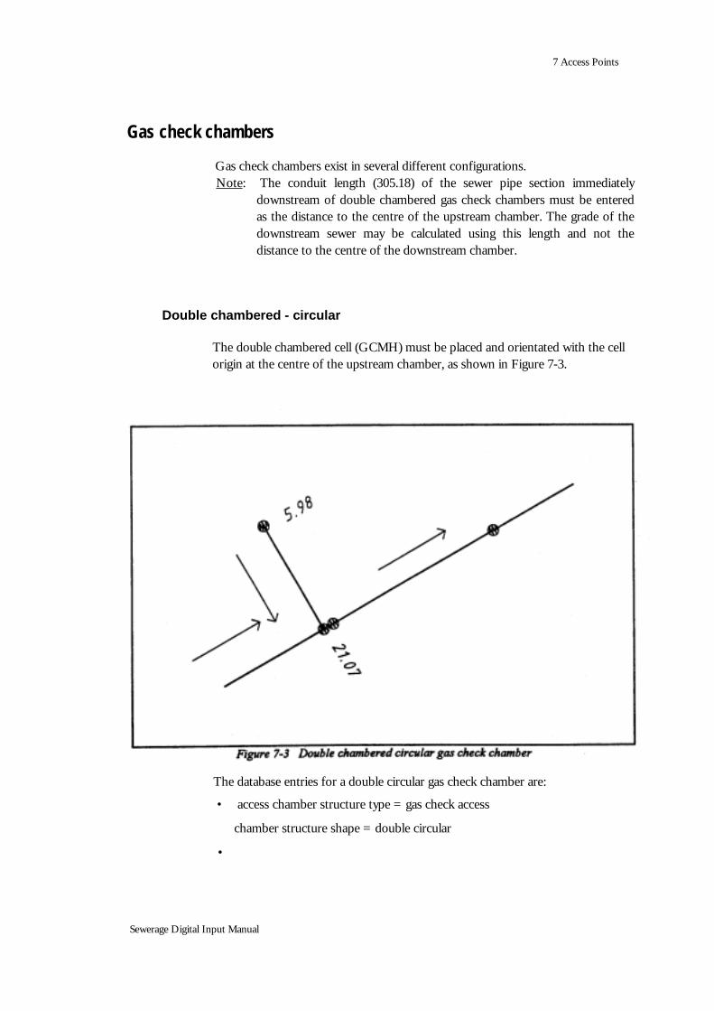
7 Access Points
Gas check chambers
Double chambered - circular
The double chambered cell (GCMH) must be placed and orientated with the cell origin at the centre of the upstream chamber, as shown in Figure 7-3.
Sewerage Digital Input Manual
The database entries for a double circular gas check chamber are:
• access chamber structure type = gas check access
chamber structure shape = double circular
•
Gas check chambers exist in several different configurations. Note: The conduit length (305.18) of the sewer pipe section immediately
downstream of double chambered gas check chambers must be entered as the distance to the centre of the upstream chamber. The grade of the downstream sewer may be calculated using this length and not the distance to the centre of the downstream chamber.
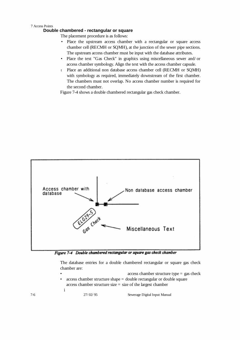
7 Access Points Double chambered - rectangular or square
The placement procedure is as follows: • Place the upstream access chamber with a rectangular or square access
chamber cell (RECMH or SQMH), at the junction of the sewer pipe sections. The upstream access chamber must be input with the database attributes.
• Place the text "Gas Check" in graphics using miscellaneous sewer and/or access chamber symbology. Align the text with the access chamber capsule.
t Place an additional non database access chamber cell (RECMH or SQMH) with symbology as required, immediately downstream of the first chamber. The chambers must not overlap. No access chamber number is required for the second chamber.
Figure 7-4 shows a double chambered rectangular gas check chamber.
The database entries for a double chambered rectangular or square gas check chamber are: • access chamber structure type = gas check • access chamber structure shape = double rectangular or double square
access chamber structure size = size of the largest chamber i
7-6 27/02/95 Sewerage Digital Input Manual

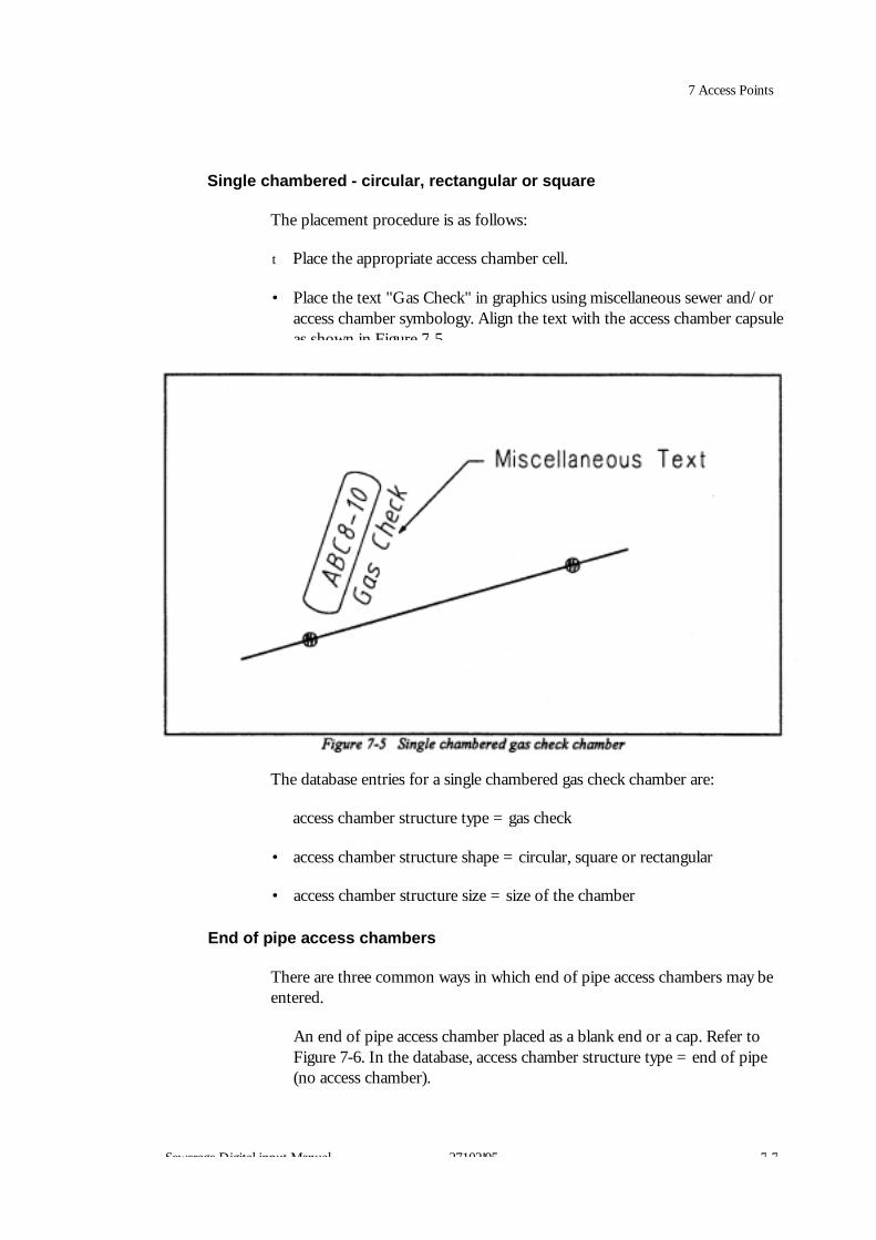
7 Access Points Single chambered - circular, rectangular or square
The placement procedure is as follows:
t Place the appropriate access chamber cell.
• Place the text "Gas Check" in graphics using miscellaneous sewer and/or access chamber symbology. Align the text with the access chamber capsule as shown in Figure 7 5
The database entries for a single chambered gas check chamber are:
access chamber structure type = gas check
• access chamber structure shape = circular, square or rectangular
• access chamber structure size = size of the chamber
End of pipe access chambers
There are three common ways in which end of pipe access chambers may be entered.
An end of pipe access chamber placed as a blank end or a cap. Refer to Figure 7-6. In the database, access chamber structure type = end of pipe (no access chamber).
Sewerage Digital input Manual 27102!95 7 7
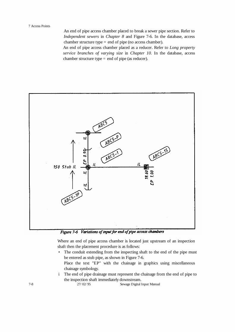
7 Access Points An end of pipe access chamber placed to break a sewer pipe section. Refer to Independent sewers in Chapter 8 and Figure 7-6. In the database, access chamber structure type = end of pipe (no access chamber). An end of pipe access chamber placed as a reducer. Refer to Long property service branches of varying size in Chapter 10. In the database, access chamber structure type = end of pipe (as reducer).
Where an end of pipe access chamber is located just upstream of an inspection shaft then the placement procedure is as follows: • The conduit extending from the inspecting shaft to the end of the pipe must
be entered as stub pipe, as shown in Figure 7-6. Place the text "EP" with the chainage in graphics using miscellaneous chainage symbology.
i The end of pipe drainage must represent the chainage from the end of pipe to the inspection shaft immediately downstream.
7-8 27/02/95 Sewage Digital Input Manual

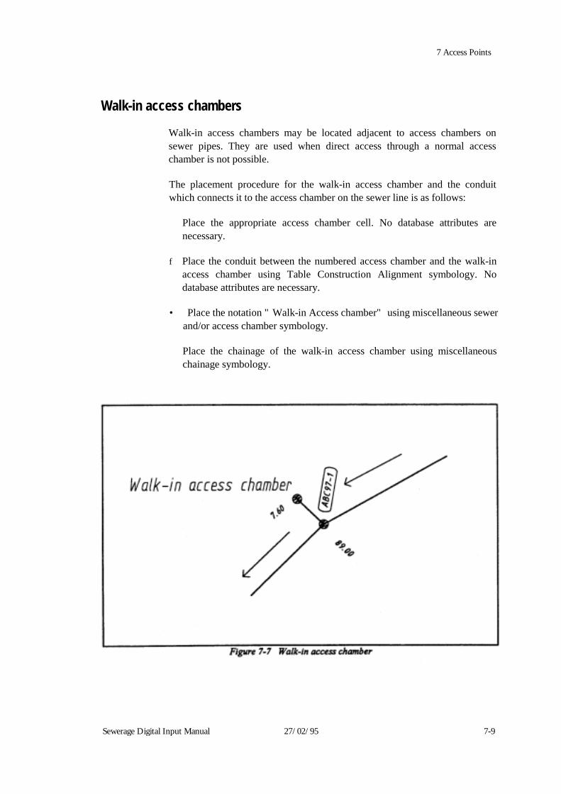
7 Access Points
Walk-in access chambers
Walk-in access chambers may be located adjacent to access chambers on sewer pipes. They are used when direct access through a normal access chamber is not possible. The placement procedure for the walk-in access chamber and the conduit which connects it to the access chamber on the sewer line is as follows:
Place the appropriate access chamber cell. No database attributes are necessary.
f Place the conduit between the numbered access chamber and the walk-in
access chamber using Table Construction Alignment symbology. No database attributes are necessary.
• Place the notation "Walk-in Access chamber" using miscellaneous sewer
and/or access chamber symbology.
Place the chainage of the walk-in access chamber using miscellaneous chainage symbology.
Sewerage Digital Input Manual 27/02/95 7-9
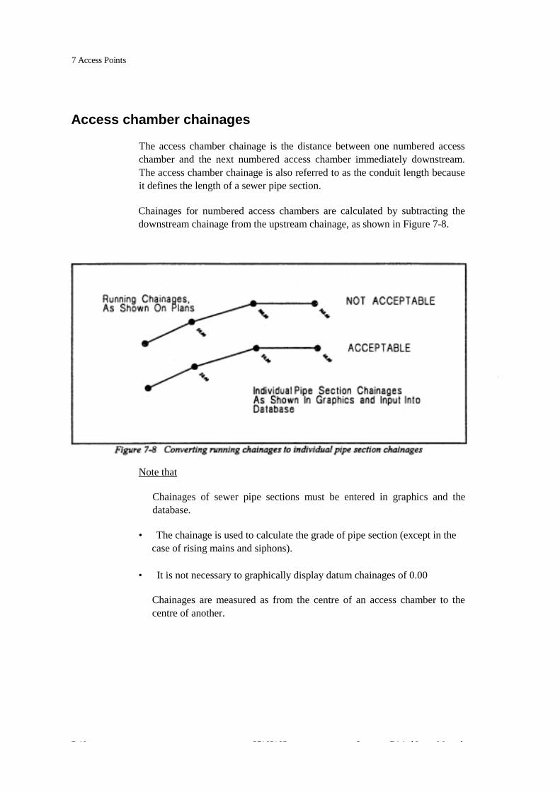
7 Access Points Access chamber chainages
The access chamber chainage is the distance between one numbered access chamber and the next numbered access chamber immediately downstream. The access chamber chainage is also referred to as the conduit length because it defines the length of a sewer pipe section.
Chainages for numbered access chambers are calculated by subtracting the downstream chainage from the upstream chainage, as shown in Figure 7-8.
Note that
Chainages of sewer pipe sections must be entered in graphics and the database.
• The chainage is used to calculate the grade of pipe section (except in the
case of rising mains and siphons).
• It is not necessary to graphically display datum chainages of 0.00
Chainages are measured as from the centre of an access chamber to the centre of another.
7 10 27/02/95 S Di i l I M l

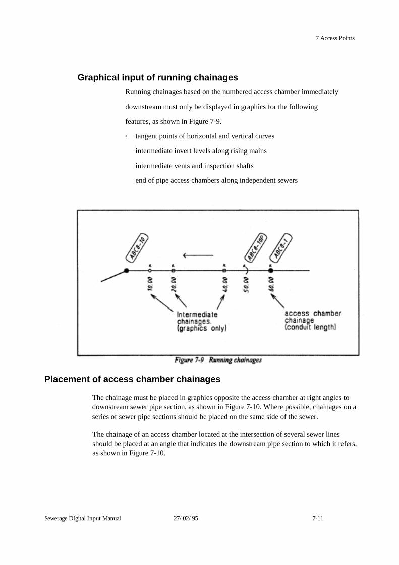
7 Access Points Graphical input of running chainages
Running chainages based on the numbered access chamber immediately
downstream must only be displayed in graphics for the following
features, as shown in Figure 7-9.
f tangent points of horizontal and vertical curves
intermediate invert levels along rising mains
intermediate vents and inspection shafts
end of pipe access chambers along independent sewers
Placement of access chamber chainages
The chainage must be placed in graphics opposite the access chamber at right angles to downstream sewer pipe section, as shown in Figure 7-10. Where possible, chainages on a series of sewer pipe sections should be placed on the same side of the sewer.
The chainage of an access chamber located at the intersection of several sewer lines should be placed at an angle that indicates the downstream pipe section to which it refers, as shown in Figure 7-10.
Sewerage Digital Input Manual 27/02/95 7-11

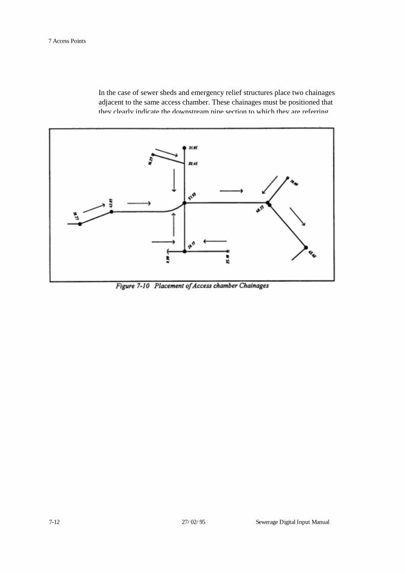
7-12 27/02/95 Sewerage Digital Input Manual
7 Access Points
In the case of sewer sheds and emergency relief structures place two chainages adjacent to the same access chamber. These chainages must be positioned that they clearly indicate the downstream pipe section to which they are referring
7 Access Points
Access chamber numbering Note: For a range of access chamber numbers for each job, consultants must
contact the job's design engineers for the numbers and verify these with the Water Company.
All access chambers other than intermediate vents, intermediate inspection shafts and minor vents must be numbered according to the conventions outlined below: f Access chamber numbers must be unique. • All access chamber numbers must be entered in the database, except for those
on private sewers. • Access chambers should always be numbered so that the numbers increase
from downstream to upstream. • Access chambers numbers are usually made up of
- a prefix of three letters and up to three numerals. - a suffix of up to eight characters (numerals and letters).
The access chamber number must not exceed 13 characters. Access chamber numbers are not to include the letter D after suffix. This D is generally placed on a design plan to signify a "drop structure" in an access chamber.
When numbering access chambers along a sewer: The three letter prefix of the upstream access chamber number should usually equal the three letter prefix of the downstream access chamber number. For example:
ABC65 will be downstream from ABC66.
• The suffix of an upstream access chamber number will usually be either:
- a number greater than the suffix of the downstream access chamber
number, for example:
ABC65-9 will be downstream from ABC65-10. Sewerage Digital Input Manual 27/02/95 7-13

7 Access Points - equal to the suffix of the downstream access chamber number plus a
designated suffix description, for example: ABC65A will be downstream from ABC65B ABC65-90 will be downstream from ABC65-90P
For a listing of access chamber types refer to Code List 307/308. Access chamber descriptions
Several types of access chambers require a single letter description to be added to the end of the access chamber number. The descriptive characters must be assigned in the alphabetic order listed below. An access chamber number may contain a series of descriptive characters. • Inspection shafts must be labelled with the characters, S, T, or U. + Vents must be labelled with the characters, V, W, X, Y, or Z. • End of pipes must be labelled with the characters, P, Q, or R • Pipe junctions must be labelled with the characters, J, K, L, M, or N. • Additional access chambers, that do not have an allocated number, must be
labelled with the characters, A, B, C, D, E, F, G, or H. • Access chambers that are constructed by "cutting into" an existing sewer will
take the sewers downstream access chamber number and have an A, B, C or D etc added to it's suffix. For example
A new access chamber constructed on an existing sewer between ABC65-90 and ABC65-91 would have a number ABC65-90A
Numbering of access chambers along named sewers
This chapter does not apply to sewerage pumping station access chambers, ERS access chambers on named sewers or ERS conduits.
Access chambers on named sewers are assigned a prefix of three letters, a number and where necessary, a description. The letters are derived from Code List 302 and based on the sewer name.
7-14 27/02/95 Severage Digital Input Manual

7 Access Points For example, if the access chambers to be numbered are located along the Croydon Main Sewer: * 209 is the code list entry number in Code List 301 for the Croydon Main
Sewer. "CRY" is the entry in Code List 302 corresponding to code list entry number 209.
Therefore all access chambers on the Croydon Main Sewer are prefixed with the letters CRY. The remainder of the access chamber numbers will consist of either a number, a description, or a combination of both. For example:
CRY1 would be the first access chamber on the Croydon Main Sewer, upstream of its outlet. CRYIP would be the first end of pipe upstream of access chamber number CRY 1.
* CRY IQ would be the second end of pipe upstream of CRY I. CRY5V would be the first vent upstream of CRY5.
Numbering of access chambers along reticulation sewers This chapter applies to unnamed access chambers along sewers less than 300mm in diameter. It does not apply to access chambers in sewerage pumping station catchments or along ERS conduits. The number of an access chamber on a reticulation sewer consists of two parts separated by a dash (-):
- The first part takes the number of the access chamber on the named sewer
to which it flows.
- The second part is assigned as an incrementing number, a descriptive character, or both.
For example, if a particular reticulation sewer flows to access chamber number CRY5 on the Croydon Main Sewer, then the first three access chambers along the reticulation sewer would be numbered CRY5-1, CRY5-2, CRY5-3.
Sevvetage Digital Input Manual 27/02/95 7-15

7 Access Points For example:
CRY5-1 is the first access chamber on a reticulation sewer upstream from CRY5 on the named sewer line,
CRY5-2 is the second access chamber on a reticulation sewer . upstream from
CRY5 on the named sewer line, CRY5-2S is the first inspection shaft upstream of
CRY5-2, * CRYS-2T is the second inspection shaft upstream of CRY5-2, f CRY5A-V is a vent at the end of reticulation sewer immediately upstream of
CRY5A on the named sewer line, CRY5-A is an additional access chamber on a reticulated sewer immediately upstream of CRYS on the named sewer line and downstream from CRY5-1,
t CRY3-3J is the first pipe junction upstream of CRY3-3 on the reticulated sewer,
f CRY3-3JS is the first inspection shaft upstream of CRY3-3J on the reticulated
sewer,
s CRY3-3K is the first pipe junction upstream of CRY3-3J on the reticulated sewer,
CRY3-3KS is the first inspection shaft upstream CRY3-3K on the reticulated sewer.
Numbering of access chambers at the point of entry to treatment plans
Access chambers on sewer pipe sections at the point of entry to treatment plants must be input with database linkages and numbered as follows:
• Access chambers on a named sewer must be numbered using the access
chamber numbering convention.
• Access chambers on a reticulation sewer must have the treatment plant number as the first part of the number. For example, M02 for treatment plant number M02.
7-16 27/02/95 Sewerage Digital Input Manual

7 Access Points Pumping station access chambers must have the prefix TPS and the treatment plant number as the first part of the number. For example, TPSM02 for treatment plant number M02.
Refer to Figure 7-14. Numbering of access chambers upstream of treatment plants
The numbering of access chambers on named sewers upstream of treatment plants is unaffected by the treatment plant number. Access chambers on reticulation sewers upstream of treatment plants must be assigned the appropriate prefix. The first part of this number is based on the number of the access chamber at the point of entry to the treatment plant. The suffixes of subsequent access chambers are numbered in the usual manner for reticulation sewers. Fore example:
TPSM02-1 is the first access chamber upstream of TPSM02 on a reticulation sewer which enters treatment plant number M02 at a pumping station. M02-1 is the first access chamber upstream of M02 on a reticulation sewer which enters treatment plant number M02 at a normal access chamber.
Refer to Figure 7-14. Numbering of pumping station access chambers
Pumping station access chambers on reticulated or named sewers must have a prefix consisting of SPS and the pumping station number.
Sewerage pumping station numbers will be supplied by the Water Company.
Pumping stations at the point of entry to treatment plants, must have a number consisting of the letters TPS and the treatment plant number.
Refer to Pumping station associated details later in this chapter, for the numbering of multiple pumps at a single pumping station.
Sewerage Digital Input Manual 27/02/95 7-17
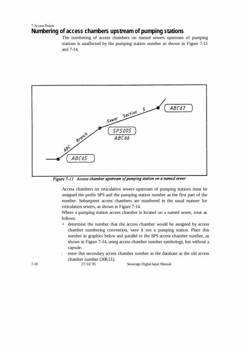
7 Access Points
Numbering of access chambers upstream of pumping stations The numbering of access chambers on named sewers upstream of pumping stations is unaffected by the pumping station number as shown in Figure 7-11 and 7-14.
Access chambers on reticulation sewers upstream of pumping stations must be assigned the prefix SPS and the pumping station number as the first part of the number. Subsequent access chambers are numbered in the usual manner for reticulation sewers, as shown in Figure 7-14. Where a pumping station access chamber is located on a named sewer, treat as follows: + determine the number that the access chamber would be assigned by access
chamber numbering convention, were it not a pumping station. Place this number in graphics below and parallel to the SPS access chamber number, as shown in Figure 7-14, using access chamber number symbology, but without a capsule.
t enter this secondary access chamber number in the database as the old access chamber number (308.51).
7-18 27/02/95 Sewerage Digital laput Manual

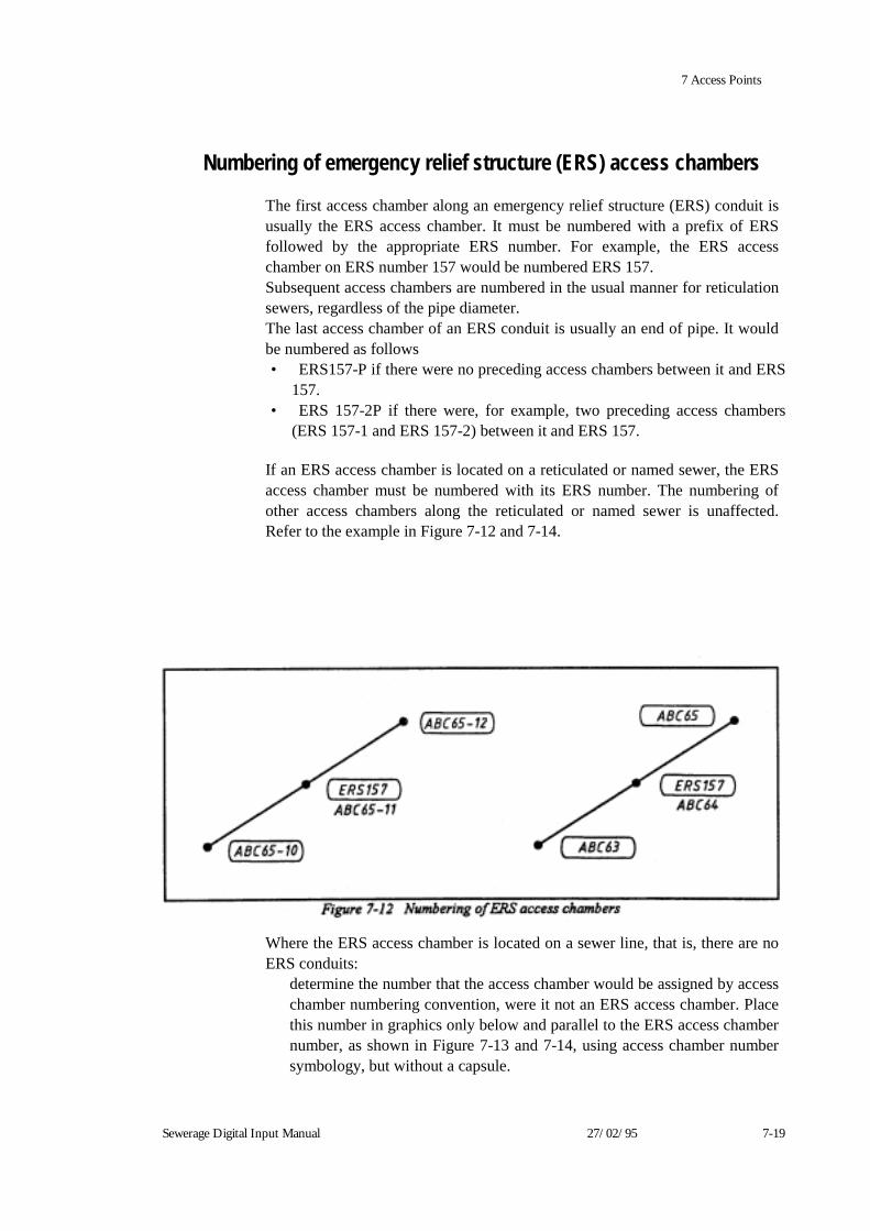
7 Access Points
Numbering of emergency relief structure (ERS) access chambers
The first access chamber along an emergency relief structure (ERS) conduit is usually the ERS access chamber. It must be numbered with a prefix of ERS followed by the appropriate ERS number. For example, the ERS access chamber on ERS number 157 would be numbered ERS 157. Subsequent access chambers are numbered in the usual manner for reticulation sewers, regardless of the pipe diameter. The last access chamber of an ERS conduit is usually an end of pipe. It would be numbered as follows • ERS157-P if there were no preceding access chambers between it and ERS
157. • ERS 157-2P if there were, for example, two preceding access chambers
(ERS 157-1 and ERS 157-2) between it and ERS 157. If an ERS access chamber is located on a reticulated or named sewer, the ERS access chamber must be numbered with its ERS number. The numbering of other access chambers along the reticulated or named sewer is unaffected. Refer to the example in Figure 7-12 and 7-14.
Where the ERS access chamber is located on a sewer line, that is, there are no ERS conduits:
determine the number that the access chamber would be assigned by access chamber numbering convention, were it not an ERS access chamber. Place this number in graphics only below and parallel to the ERS access chamber number, as shown in Figure 7-13 and 7-14, using access chamber number symbology, but without a capsule.
Sewerage Digital Input Manual 27/02/95 7-19
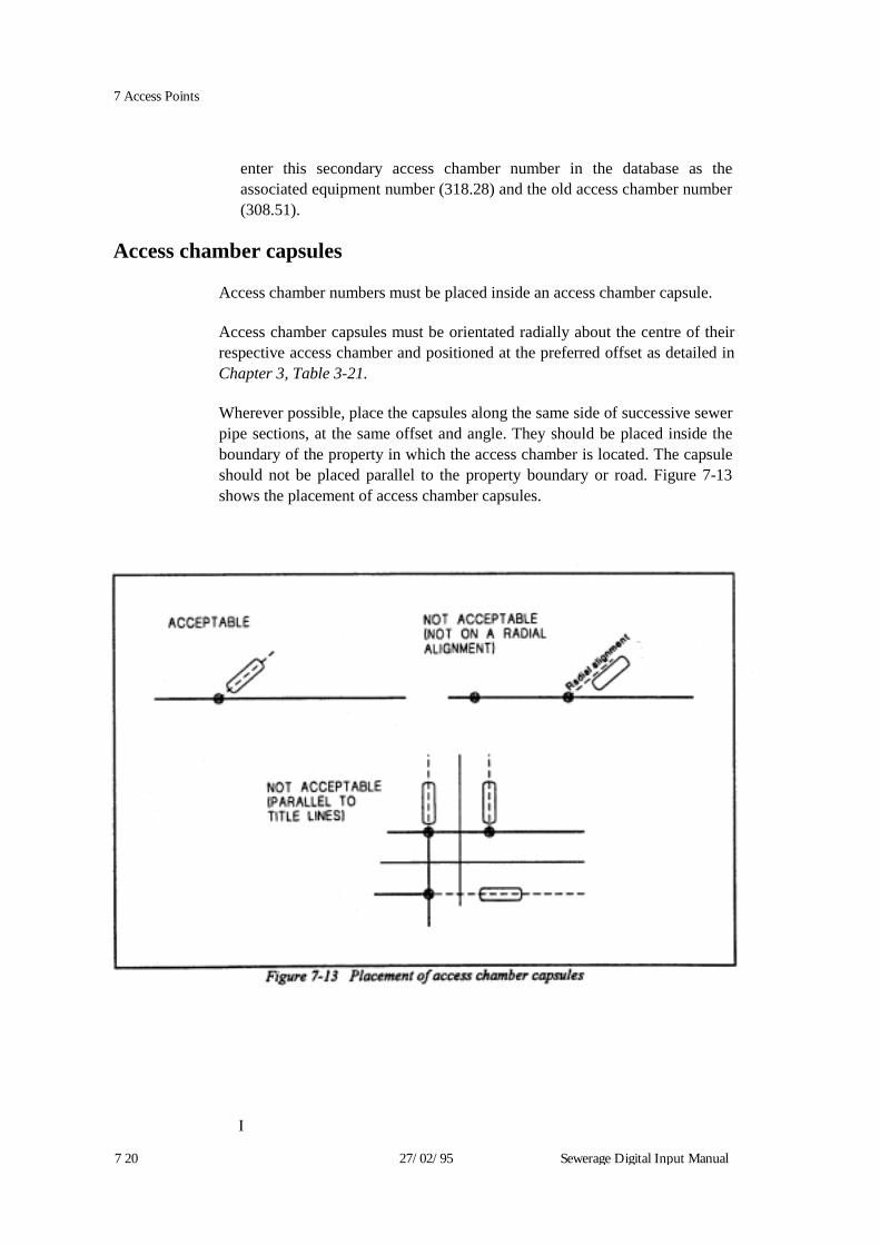
I 7 20 27/02/95 Sewerage Digital Input Manual
7 Access Points
enter this secondary access chamber number in the database as the associated equipment number (318.28) and the old access chamber number (308.51).
Access chamber capsules
Access chamber numbers must be placed inside an access chamber capsule.
Access chamber capsules must be orientated radially about the centre of their respective access chamber and positioned at the preferred offset as detailed in Chapter 3, Table 3-21.
Wherever possible, place the capsules along the same side of successive sewer pipe sections, at the same offset and angle. They should be placed inside the boundary of the property in which the access chamber is located. The capsule should not be placed parallel to the property boundary or road. Figure 7-13 shows the placement of access chamber capsules.

7 Access Points
Trunk sewer access shaft name
The trunk sewer access shaft name should be placed in graphics in upper case at an active angle of zero degrees (horizontal), opposite the centre of the shaft.
Note: The name should be shown on the plan. The name can be verified, if
necessary in Code List 305. If there is a discrepancy, place the name indicated in the code list.
Trunk sewer access shafts must be designated a unique access chamber number in the same manner as standard access chambers and a name.
Sewerage Digital Input Manual 27/02/95 7 21

7 Access Points
Sewerage pumping station access chambers Pumping station access chambers also define sewer pipe and rising main sections. The symbology of pumping station access chambers varies according to the size of the pumping station, not the size range of the downstream pipe station. Pumping station access chambers are considered to be major if they have been designated as such in Code List 349. Major pumping station access chambers must be scaled in graphics according to their size. Minor pumping station access chambers must not be scaled.
Database Pumping Station Access chambers (entity 315) are identified by a unique access chamber number designated by the Water Company. Since they are owned by the Access chamber entity (308) and the Pumping Station entity (315) they have a dual set of attributes. Refer to the Database Schedules in Chapter 2 for details of pumping station attributes. The access chamber structure type (308.12) is Pump Station.
Pump station name - The pumping station name (315.10) is derived from Code List 349 and corresponds to the pumping station access chamber number (as found in Code List 350); the two code lists are linked by common entry numbers. For example, if the pumping station access chamber number is SPS 123
* "128" is the code list entry number in Code List 350 for Sewerage
Pumping Station "123".
i "Margaret St" is the entry in Code List 349 corresponding to code list entry number 128.
The sewerage pumping station name is only required to be placed in graphics for major pumping stations. The name should be input in upper case at an active angle of zero degrees (horizontal) opposite the access chamber.
I 7 22 27/02/95 Sewerage Digital Input Manual
7 Access Points
Pumping station associated details A number of features are commonly associated with pumping stations.
Electrical control cabinet The cell name for an electrical control cabinet is ECC. It should be placed in the appropriate position and orientated according to the plan.
Valve pit The cell name for a valve pit is VALPIT. This cell represents a Reflux valve and should be placed on the rising main outlet pipes in the appropriate position and orientation. It is not necessary to input the external shape of the valve pit structure.
Pipework and buildings Pipework and buildings should be shown for major sewerage pumping stations. The pipework should be shown as graphics. Major buildings should be shown as outlines.
Additional pumps Some sewerage pumping stations contain more than one pumping station access chamber.
In cases where there is no separate name for each pumping station, input each pump into graphics and the database.
Assign access chamber numbers to each pump, using pump station number as normal, and a descriptive letter (A to H) as required, for each additional pump. For example, at the Brooklyn Pumping Station, multiple pumps would be numbered SPS005A, SPS005B, SPS005C and so on. In the database assign multiple pumps at a single pump station, the same pumping station name. In the above example, all pumps would be owned by the Brooklyn Pumping Station, entry number 10 in the Code List 349.
Multiple outlet rising main pipework
Pumping stations usually have one or more short lengths of outlet pipe that connect to the primary rising main. These outlet pipes should only be placed in graphics.
Sewerage Digital Input Manual 27/02/95 7-23

7 Access Points
Emergency relief structure access chambers Each emergency relief structure (ERS) has a specially designed access chamber associated with it. The cell ERS must be placed to represent this structure. Other access chambers located along the ERS conduit must be placed as standard access chambers. The ERS access chamber is usually located at the end of the first section of ERS conduit. This is the pipe section which connects directly to the access chamber or pumping station on the sewer line. In some cases the ERS access chamber may be located on the sewer line itself as a normal access chamber.
Database The ERS Access chamber entity (318) is owned by the Sewer Access chamber entity (308). It therefore has a dual set of attributes. Refer to the Database Schedule in Chapter 2 for a complete list of attributes.
The database entries for access chambers placed as the ERS cell are as follows:
access chamber number = ERSnnn, where nnn is the number of the ERS.
t access chamber structure type = Emergency Relief Structure.
t associated equipment type = Pumping Station or Access chamber, as appropriate.
• associated equipment type number = the access chamber number of the
pumping station or access chamber.
Note: The associated equipment type and number attributes refer to the structure on the sewer line which the ERS has been constructed to relieve.
7-24 27/02/95 Sewerage Digital Input Manual

7 Access Points Graphical placement
The circular ERS cell must be placed as the ERS access chamber in all cases.
Where the shape of the access chamber is not circular:
• place an appropriate shape in graphics around the ERS cell with the same symbology.
* enter the appropriate shape in the database for access chamber structure
shape.
Sewerage Digital Input Manual 27/02/95 7 25
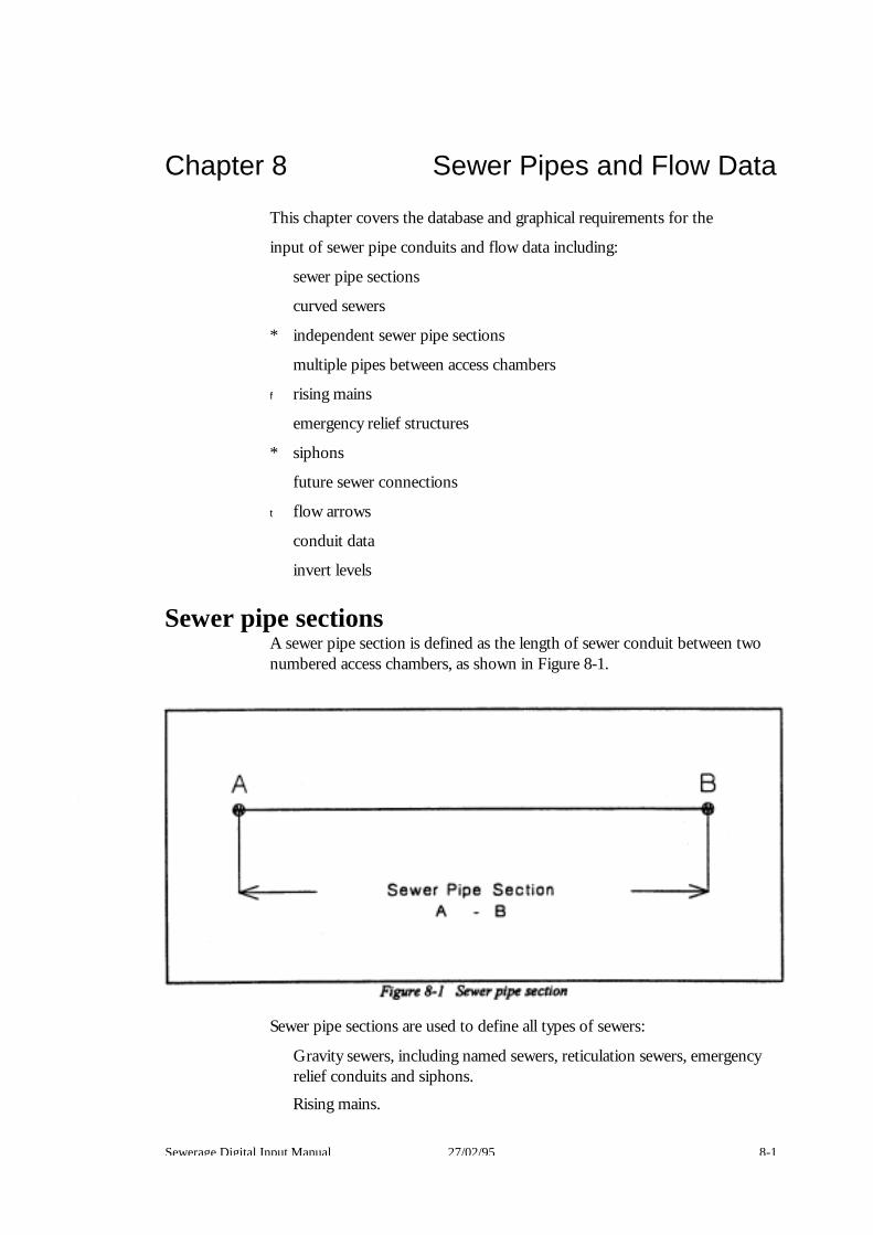
Chapter 8 Sewer Pipes and Flow Data
This chapter covers the database and graphical requirements for the
input of sewer pipe conduits and flow data including:
sewer pipe sections
curved sewers
* independent sewer pipe sections
multiple pipes between access chambers
f rising mains
emergency relief structures
* siphons
future sewer connections
t flow arrows
conduit data
invert levels Sewer pipe sections
A sewer pipe section is defined as the length of sewer conduit between two numbered access chambers, as shown in Figure 8-1.
Sewer pipe sections are used to define all types of sewers:
Gravity sewers, including named sewers, reticulation sewers, emergency relief conduits and siphons.
Rising mains.
Sewerage Digital Input Manual 27/02/95 8-1

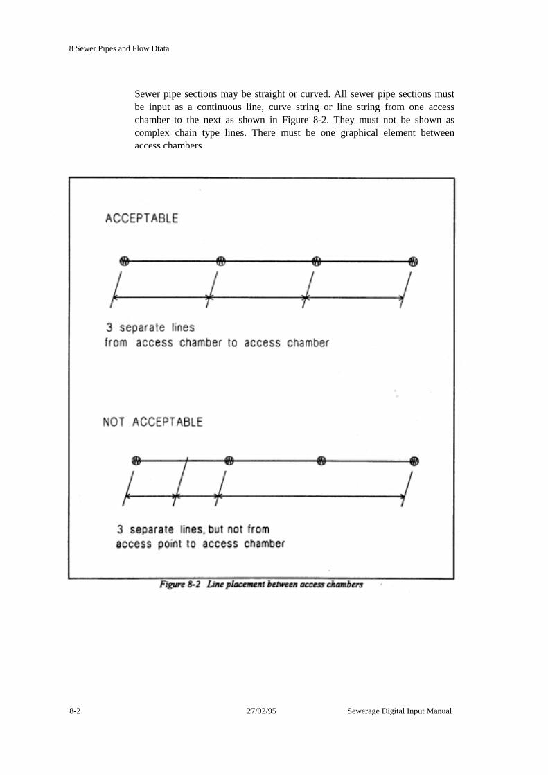
8 Sewer Pipes and Flow Dtata
Sewer pipe sections may be straight or curved. All sewer pipe sections must be input as a continuous line, curve string or line string from one access chamber to the next as shown in Figure 8-2. They must not be shown as complex chain type lines. There must be one graphical element between access chambers.
8-2 27/02/95 Sewerage Digital Input Manual

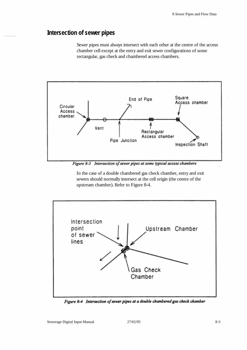
8 Sewer Pipes and Flow Data
Intersection of sewer pipes
Sewer pipes must always intersect with each other at the centre of the access chamber cell except at the entry and exit sewer configurations of some rectangular, gas check and chambered access chambers.
In the case of a double chambered gas check chamber, entry and exit sewers should normally intersect at the cell origin (the centre of the upstream chamber). Refer to Figure 8-4.
Sewerage Digital Input Manual 27/02/95 8-3
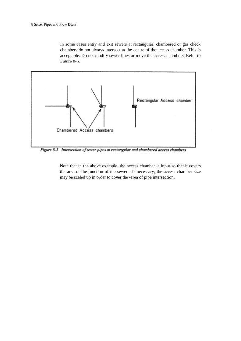
8 Sewer Pipes and Flow Dtata
In some cases entry and exit sewers at rectangular, chambered or gas check chambers do not always intersect at the centre of the access chamber. This is acceptable. Do not modify sewer lines or move the access chambers. Refer to Figure 8-5.
Note that in the above example, the access chamber is input so that it covers the area of the junction of the sewers. If necessary, the access chamber size may be scaled up in order to cover the -area of pipe intersection.

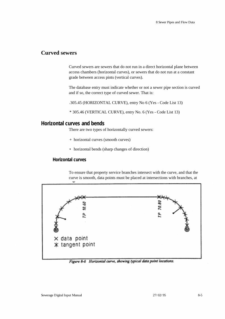
8 Sewer Pipes and Flow Data
Curved sewers
Curved sewers are sewers that do not run in a direct horizontal plane between access chambers (horizontal curves), or sewers that do not run at a constant grade between access pints (vertical curves).
The database entry must indicate whether or not a sewer pipe section is curved and if so, the correct type of curved sewer. That is:
t 305.45 (HORIZONTAL CURVE), entry No 6 (Yes - Code List 13)
* 305.46 (VERTICAL CURVE), entry No. 6 (Yes - Code List 13) Horizontal curves and bends
There are two types of horizontally curved sewers:
+ horizontal curves (smooth curves)
• horizontal bends (sharp changes of direction)
Horizontal curves
To ensure that property service branches intersect with the curve, and that the curve is smooth, data points must be placed at intersections with branches, at
Sewerage Digital Input Manual 27/02/95 8-5
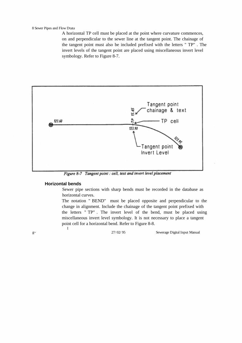
8 Sewer Pipes and Flow Dtata A horizontal TP cell must be placed at the point where curvature commences, on and perpendicular to the sewer line at the tangent point. The chainage of the tangent point must also be included prefixed with the letters "TP". The invert levels of the tangent point are placed using miscellaneous invert level symbology. Refer to Figure 8-7.
Horizontal bends Sewer pipe sections with sharp bends must be recorded in the database as horizontal curves. The notation "BEND" must be placed opposite and perpendicular to the change in alignment. Include the chainage of the tangent point prefixed with the letters "TP". The invert level of the bend, must be placed using miscellaneous invert level symbology. It is not necessary to place a tangent point cell for a horizontal bend. Refer to Figure 8-8.
I g~ 27/02/95 Sewerage Digital Input Manual

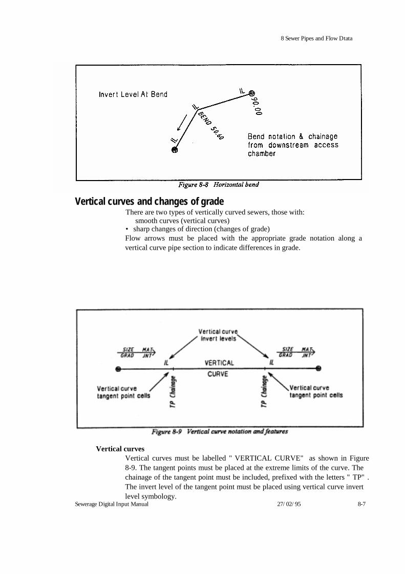
8 Sewer Pipes and Flow Dtata
Vertical curves and changes of gradeThere are two types of vertically curved sewers, those with:
smooth curves (vertical curves) • sharp changes of direction (changes of grade) Flow arrows must be placed with the appropriate grade notation along a vertical curve pipe section to indicate differences in grade.
Vertical curves Vertical curves must be labelled "VERTICAL CURVE" as shown in Figure 8-9. The tangent points must be placed at the extreme limits of the curve. The chainage of the tangent point must be included, prefixed with the letters "TP". The invert level of the tangent point must be placed using vertical curve invert level symbology.
Sewerage Digital Input Manual 27/02/95 8-7
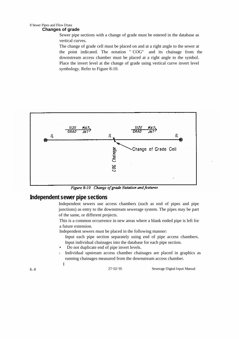
8 Sewer Pipes and Flow Dtata Changes of grade
Sewer pipe sections with a change of grade must be entered in the database as vertical curves. The change of grade cell must be placed on and at a right angle to the sewer at the point indicated. The notation "COG" and its chainage from the downstream access chamber must be placed at a right angle to the symbol. Place the invert level at the change of grade using vertical curve invert level symbology. Refer to Figure 8-10.
Independent sewer pipe sectionsIndependent sewers use access chambers (such as end of pipes and pipe junctions) as entry to the downstream sewerage system. The pipes may be part of the same, or different projects. This is a common occurrence in new areas where a blank ended pipe is left for a future extension. Independent sewers must be placed in the following manner:
Input each pipe section separately using end of pipe access chambers. Input individual chainages into the database for each pipe section.
• Do not duplicate end of pipe invert levels. f Individual upstream access chamber chainages are placed in graphics as
running chainages measured from the downstream access chamber. I
g_.g 27/02/95 Sewerage Digital Input Manual
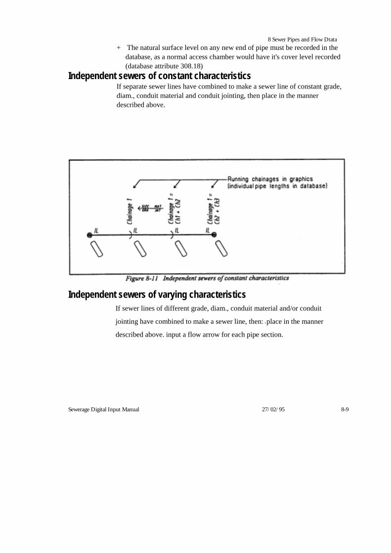
8 Sewer Pipes and Flow Dtata + The natural surface level on any new end of pipe must be recorded in the
database, as a normal access chamber would have it's cover level recorded (database attribute 308.18)
Independent sewers of constant characteristics If separate sewer lines have combined to make a sewer line of constant grade, diam., conduit material and conduit jointing, then place in the manner described above.
Independent sewers of varying characteristicsIf sewer lines of different grade, diam., conduit material and/or conduit
jointing have combined to make a sewer line, then: t place in the manner
described above. input a flow arrow for each pipe section. Sewerage Digital Input Manual 27/02/95 8-9

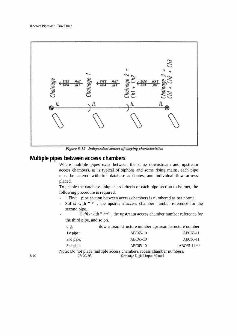
8 Sewer Pipes and Flow Dtata
Multiple pipes between access chambersWhere multiple pipes exist between the same downstream and upstream access chambers, as is typical of siphons and some rising mains, each pipe must be entered with full database attributes, and individual flow arrows placed. To enable the database uniqueness criteria of each pipe section to be met, the following procedure is required: - `First" pipe section between access chambers is numbered as per normal. - Suffix with "*", the upstream access chamber number reference for the
second pipe. - Suffix with "**", the upstream access chamber number reference for
the third pipe, and so on. e.g. downstream structure number upstream structure number 1st pipe: ABC65-10 ABC65-11 2nd pipe: ABC65-10 ABC65-11 3rd pipe : ABC65-10 ABC65-11 **
Note: Do not place multiple access chambers/access chamber numbers. 8-10 27/02/95 Sewerage Digital Input Manual
8 Sewer Pipes and Flow Data
Rising mains Rising mains are sewer conduits of various sizes through which sewage is pumped under pressure. When digitally representing a rising main: + Input the rising main as a continuous line, from pumping station to outlet
access chamber, except when there is a change in size, material or status. • Use horizontal curve tangent point cells to indicate intermediate invert
levels and chainage locations. • All invert levels along the rising main, other than those at the pumping
station and outlet access chamber, must be shown in graphics using miscellaneous invert level symbology.
t Chainages of all features along the rising main, other than those at the pumping station and outlet access chamber, must be shown as running chainages, using miscellaneous chainage symbology. This includes intermediate invert level locations.
Any access chamber structures along the rising main between the pumping station and outlet access chamber are usually shown in graphics only.
Flow arrows on rising mains of constant characteristics, should be placed at least once every 500 metres (ground scale).
* The text RM replaces grade on the flow arrow.
* Flow arrows point in the overall direction of flow.
Change of rising main size, material, status or number of conduits
Changes may occur in the rising main conduit dia., material, status, or the number of conduits comprising the rising main. Such changes normally occur at roads, railway lines or rivers. Changes may occur over a significant length (more than 10% of the total length of the rising main) or an insignificant length (less than 10% of the total length of the rising main) and should be treated in the following manner
Change in size and/or material:
Over an insignificant length:
Sewerage Digital Input Manual 27/02/95 8-11


8 Sewer Pipes and Flow Dtata
levels, chainages etc and place pipe junction access chambers where the pipes meet the old.
b) Supply to the Water Company a hard copy field note of the rising
main section that has been abandoned
Sewerage Digital Input Manual 27/02/95 8-13
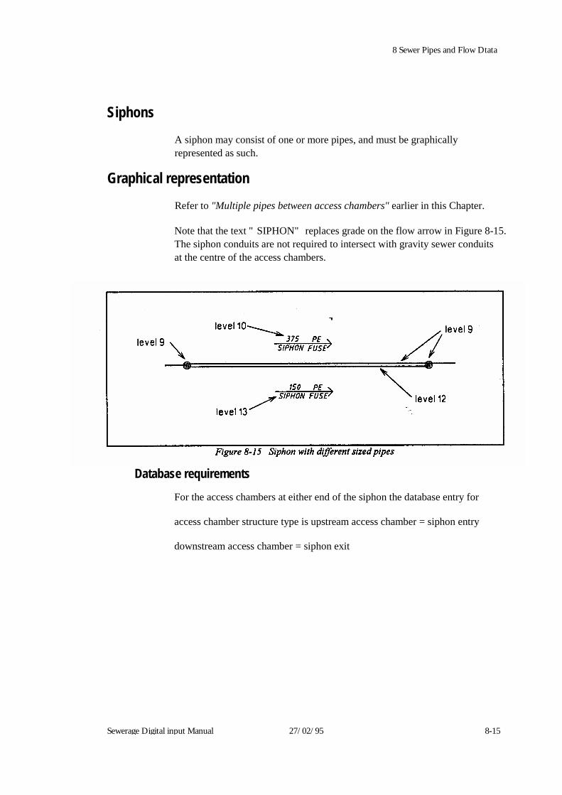
8 Sewer Pipes and Flow Dtata
Siphons
A siphon may consist of one or more pipes, and must be graphically represented as such.
Graphical representation
Refer to "Multiple pipes between access chambers" earlier in this Chapter.
Note that the text "SIPHON" replaces grade on the flow arrow in Figure 8-15. The siphon conduits are not required to intersect with gravity sewer conduits at the centre of the access chambers.
Database requirementsFor the access chambers at either end of the siphon the database entry for
access chamber structure type is upstream access chamber = siphon entry
downstream access chamber = siphon exit Sewerage Digital input Manual 27/02/95 8-15

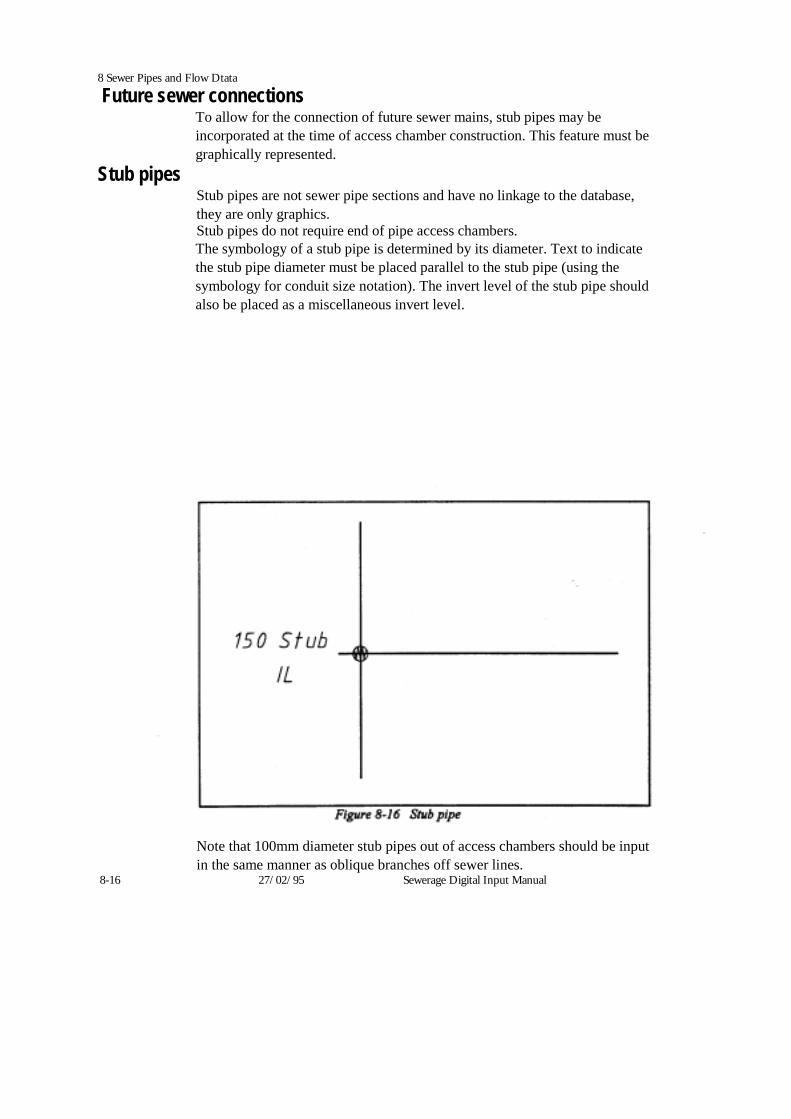
8 Sewer Pipes and Flow Dtata
Future sewer connections To allow for the connection of future sewer mains, stub pipes may be incorporated at the time of access chamber construction. This feature must be graphically represented.
Stub pipes Stub pipes are not sewer pipe sections and have no linkage to the database, they are only graphics. Stub pipes do not require end of pipe access chambers. The symbology of a stub pipe is determined by its diameter. Text to indicate the stub pipe diameter must be placed parallel to the stub pipe (using the symbology for conduit size notation). The invert level of the stub pipe should also be placed as a miscellaneous invert level.
Note that 100mm diameter stub pipes out of access chambers should be input in the same manner as oblique branches off sewer lines.
8-16 27/02/95 Sewerage Digital Input Manual

8 Sewer Pipes and Flow Dtata Table constructions
Table constructions are not sewer pipes, but formations in the base of access chambers to allow for the construction of a stub pipe and connecting sewer in the future.
Table construction information is not shown in graphics or stored in the database.
Sewerage Digital Input Manual 27/02/95 8-17
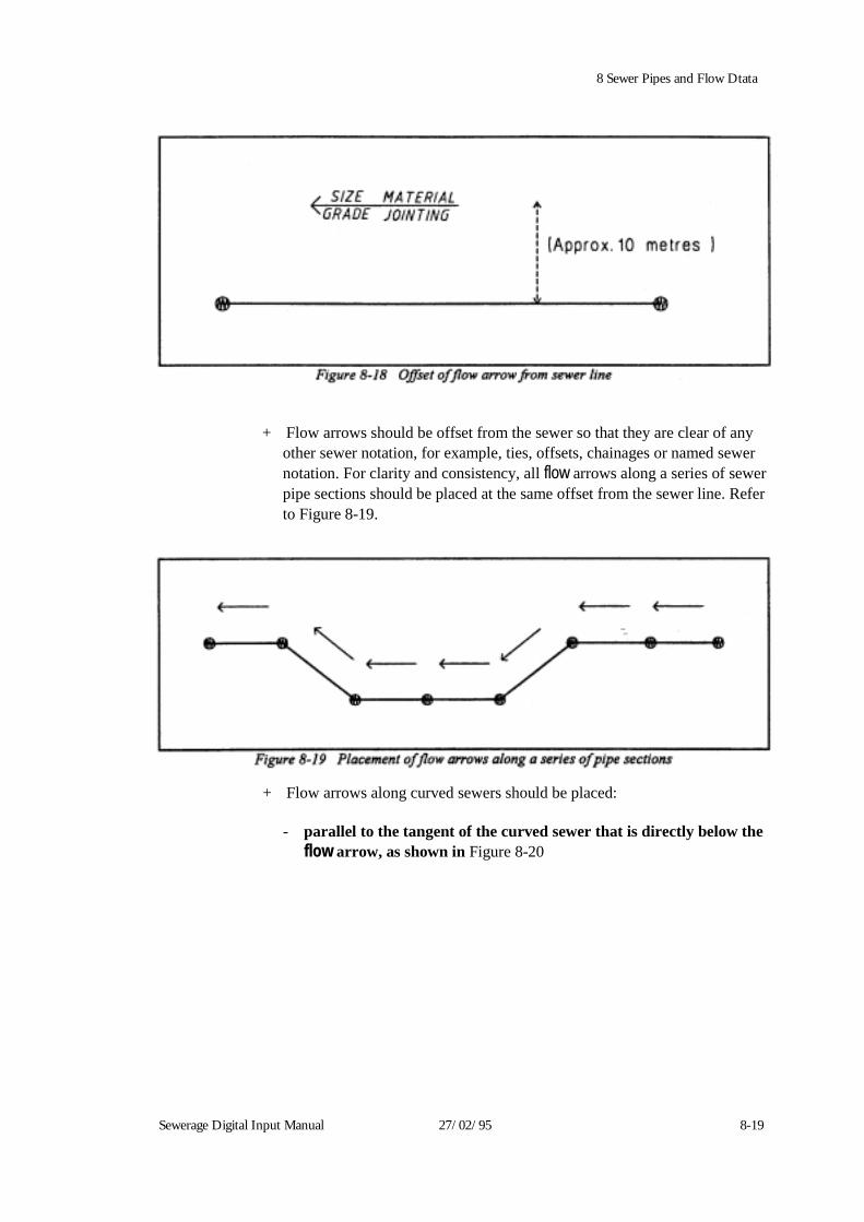
8 Sewer Pipes and Flow Dtata
+ Flow arrows should be offset from the sewer so that they are clear of any other sewer notation, for example, ties, offsets, chainages or named sewer notation. For clarity and consistency, all flow arrows along a series of sewer pipe sections should be placed at the same offset from the sewer line. Refer to Figure 8-19.
Sewerage Digital Input Manual 27/02/95 8-19
+ Flow arrows along curved sewers should be placed:
- parallel to the tangent of the curved sewer that is directly below the flow arrow, as shown in Figure 8-20
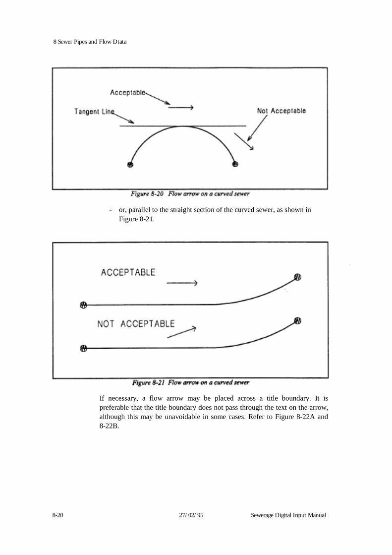
8 Sewer Pipes and Flow Dtata
- or, parallel to the straight section of the curved sewer, as shown in Figure 8-21.
If necessary, a flow arrow may be placed across a title boundary. It is preferable that the title boundary does not pass through the text on the arrow, although this may be unavoidable in some cases. Refer to Figure 8-22A and 8-22B.
8-20 27/02/95 Sewerage Digital Input Manual
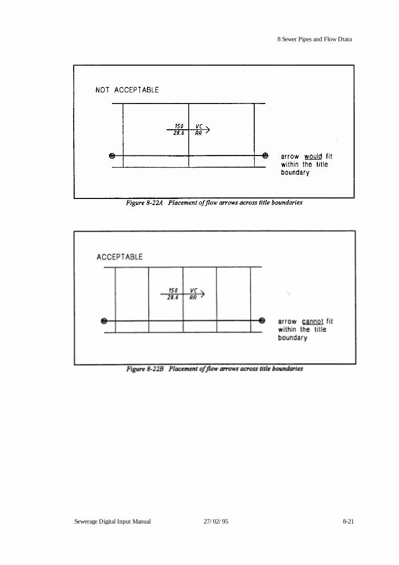
Sewerage Digital Input Manual 27/02/95 8-21
8 Sewer Pipes and Flow Dtata
8 Sewer Pipes and Flow Dtata Conduit data
Conduit data to be displayed on flow arrows consists of
+ conduit size
conduit grade
+ conduit material; and
joint packing material Conduit size
The conduit size displayed on the flow arrow must be the same as the size input into the database from Code List number 41.
Circular conduits The size of a circular conduit is defined as the nominal diameter. Code List 41 includes all standard normal diameters. If the exact nominal diameter for a conduit is not listed, contact the Water Company for advice. Do not use the nearest conduit size.
Non circular conduits
Square, ovoid and irregular shaped pipes are measured by height and width. Select the closet size from Code List 41 for which both dimensions are within 25mm of those required.
Conduit grade
Variations in grade
The representation of variations in grade along sewer pipes were discussed earlier in this chapter.
Reverse grade
For gravity sewers with an uphill grade (that is, the downstream invert level of the pipe section is higher than the upstream invert level), the flow arrow must point "uphill" in the direction of overall flow (as for rising mains). The grade is then calculated as normal.
The database entries for the invert levels are entered so that the downstream invert level is greater than the upstream invert level.
Do not prefix a reverse grade with a negative sign. 8-22 27/02/95 Sewerage Digital Input Manual

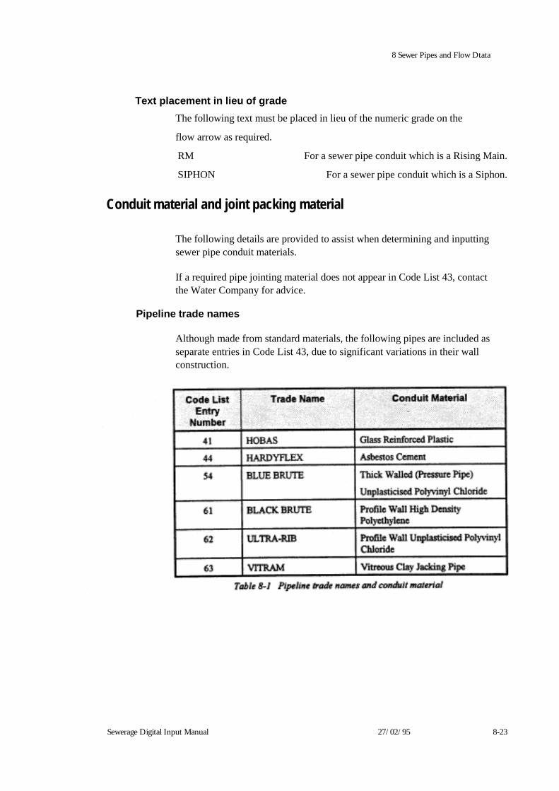
Sewerage Digital Input Manual 27/02/95 8-23
8 Sewer Pipes and Flow Dtata
Text placement in lieu of grade The following text must be placed in lieu of the numeric grade on the
flow arrow as required.
RM For a sewer pipe conduit which is a Rising Main.
SIPHON For a sewer pipe conduit which is a Siphon. Conduit material and joint packing material
The following details are provided to assist when determining and inputting sewer pipe conduit materials.
If a required pipe jointing material does not appear in Code List 43, contact the Water Company for advice.
Pipeline trade names
Although made from standard materials, the following pipes are included as separate entries in Code List 43, due to significant variations in their wall construction.
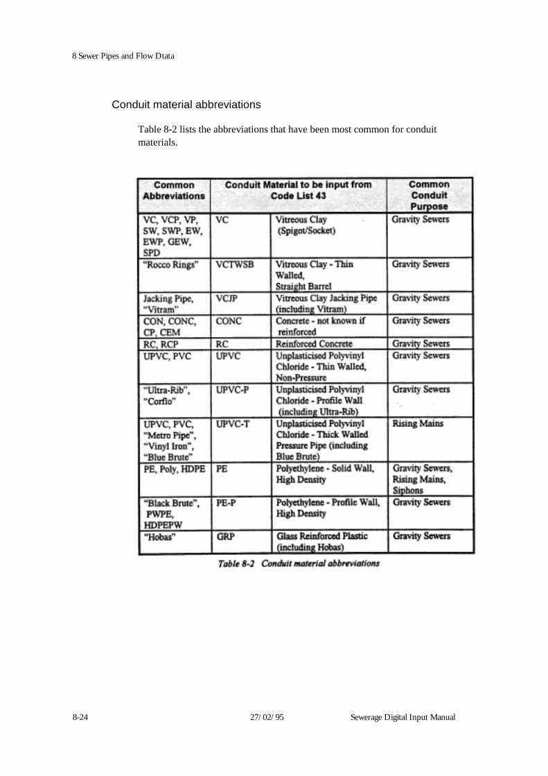
8 Sewer Pipes and Flow Dtata
Conduit material abbreviations
Table 8-2 lists the abbreviations that have been most common for conduit materials.
8-24 27/02/95 Sewerage Digital Input Manual
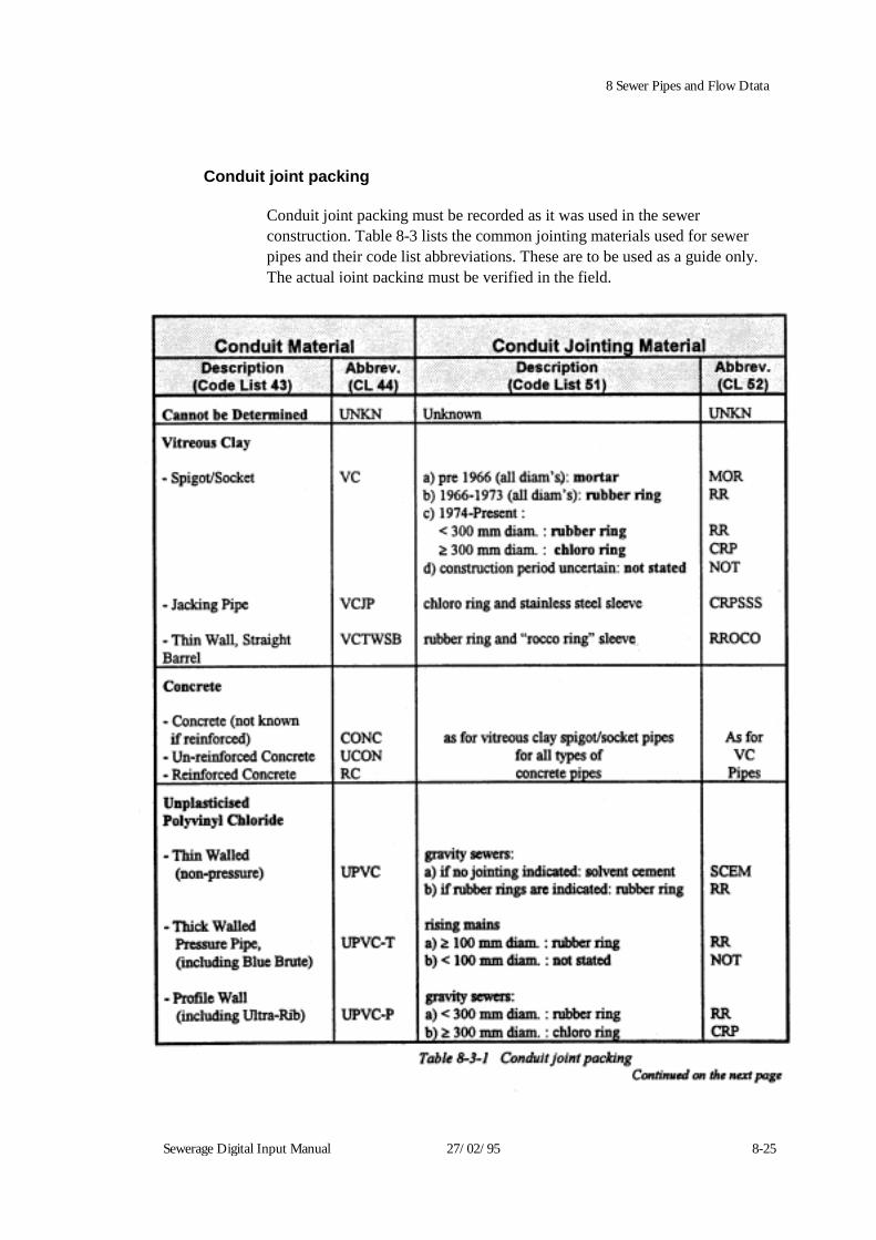
8 Sewer Pipes and Flow Dtata Conduit joint packing
Conduit joint packing must be recorded as it was used in the sewer construction. Table 8-3 lists the common jointing materials used for sewer pipes and their code list abbreviations. These are to be used as a guide only. The actual joint packing must be verified in the field.
Sewerage Digital Input Manual 27/02/95 8-25

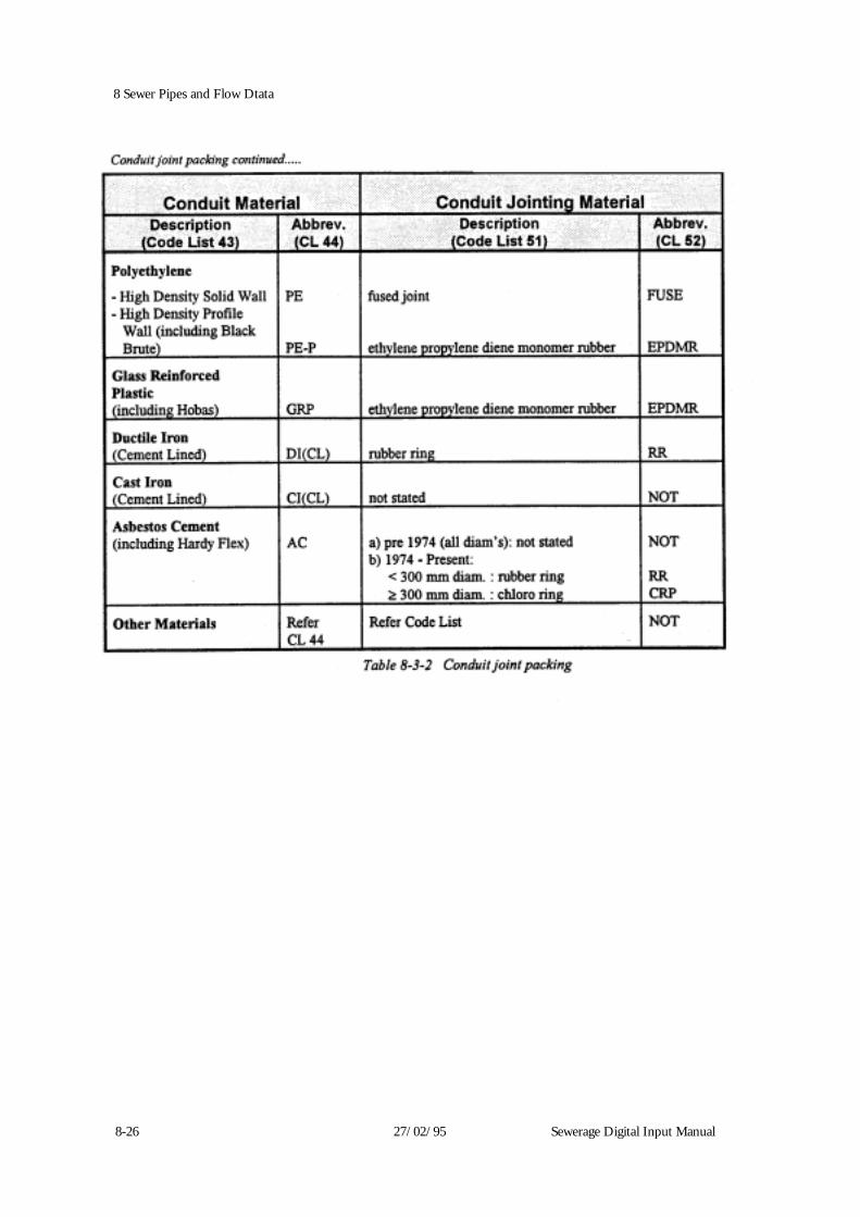
8-26 27/02/95 Sewerage Digital Input Manual
8 Sewer Pipes and Flow Dtata
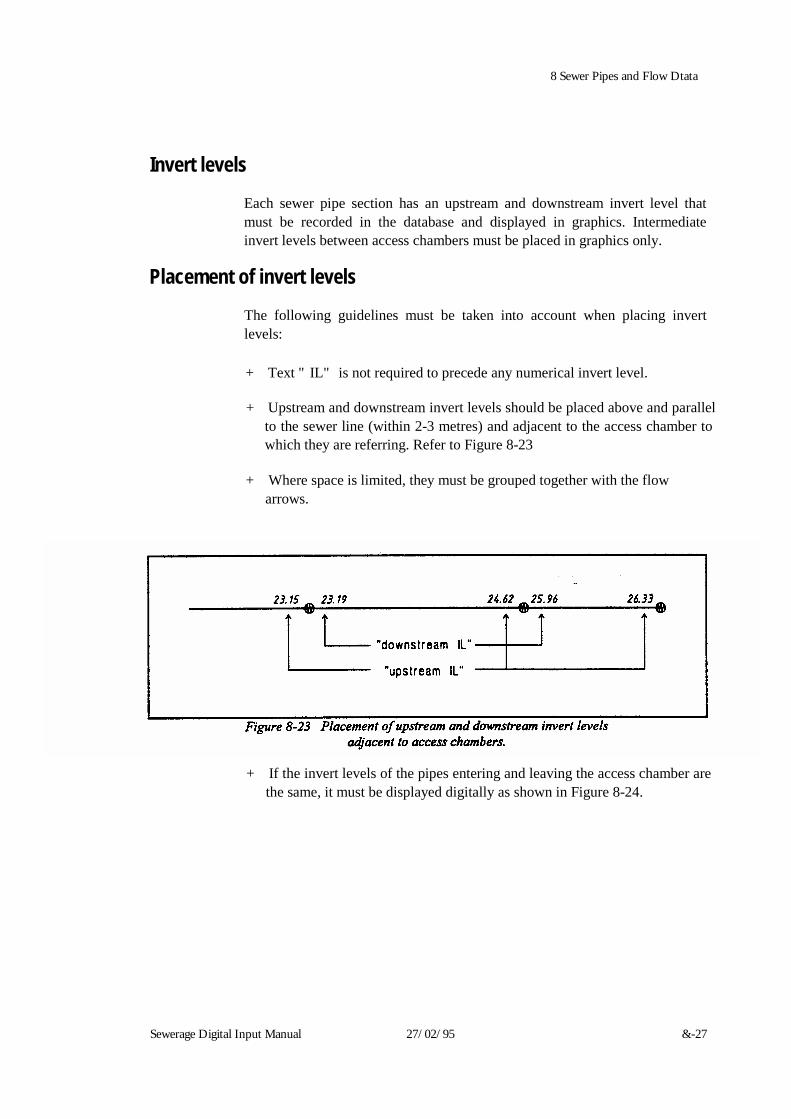
Sewerage Digital Input Manual 27/02/95 &-27
8 Sewer Pipes and Flow Dtata
Invert levels
Each sewer pipe section has an upstream and downstream invert level that must be recorded in the database and displayed in graphics. Intermediate invert levels between access chambers must be placed in graphics only.
Placement of invert levels
The following guidelines must be taken into account when placing invert levels:
+ Text "IL" is not required to precede any numerical invert level.
+ Upstream and downstream invert levels should be placed above and parallel
to the sewer line (within 2-3 metres) and adjacent to the access chamber to which they are referring. Refer to Figure 8-23
+ Where space is limited, they must be grouped together with the flow
arrows.
+ If the invert levels of the pipes entering and leaving the access chamber are the same, it must be displayed digitally as shown in Figure 8-24.
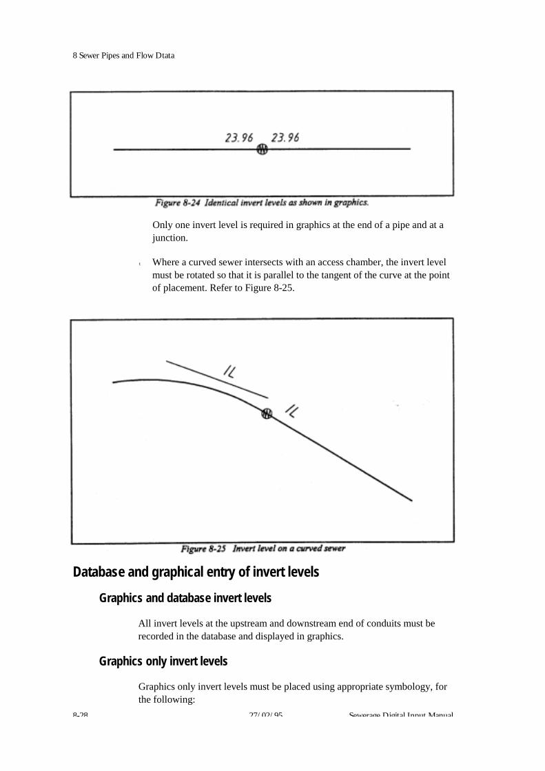
8 Sewer Pipes and Flow Dtata
Only one invert level is required in graphics at the end of a pipe and at a junction.
t Where a curved sewer intersects with an access chamber, the invert level
must be rotated so that it is parallel to the tangent of the curve at the point of placement. Refer to Figure 8-25.
Database and graphical entry of invert levels
Graphics and database invert levels
All invert levels at the upstream and downstream end of conduits must be recorded in the database and displayed in graphics.
Graphics only invert levels
Graphics only invert levels must be placed using appropriate symbology, for the following:
8-28 27/02/95 Sewerage Digital Input Manual

8 Sewer Pipes and Flow Dtata
* miscellaneous invert levels. For example:
- at intermediate points along rising mains
- at tangent points on horizontal curves
- stub pipes
at vertical curve tangent points and at changes of grade.
Sewerage Digital Input Manual 27/02/95 8-29
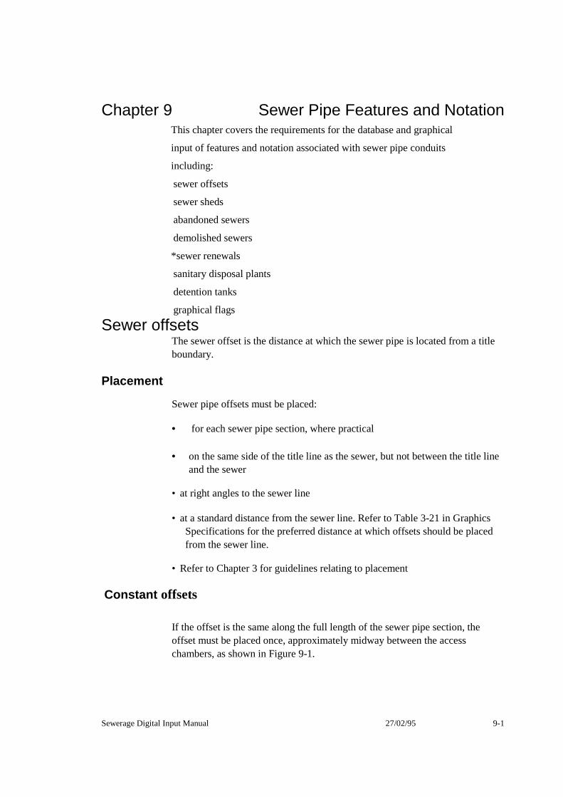
Chapter 9 Sewer Pipe Features and NotationThis chapter covers the requirements for the database and graphical
input of features and notation associated with sewer pipe conduits
including:
sewer offsets
sewer sheds
abandoned sewers
demolished sewers
*sewer renewals
sanitary disposal plants
detention tanks
graphical flags Sewer offsets
The sewer offset is the distance at which the sewer pipe is located from a title boundary.
Placement
Sewer pipe offsets must be placed:
• for each sewer pipe section, where practical
• on the same side of the title line as the sewer, but not between the title line and the sewer
•at right angles to the sewer line
•at a standard distance from the sewer line. Refer to Table 3-21 in Graphics
Specifications for the preferred distance at which offsets should be placed from the sewer line.
•Refer to Chapter 3 for guidelines relating to placement
Constant offsets
If the offset is the same along the full length of the sewer pipe section, the offset must be placed once, approximately midway between the access chambers, as shown in Figure 9-1.
Sewerage Digital Input Manual 27/02/95 9-1

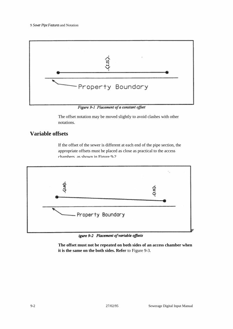
9-2 27/02/95 Sewerage Digital Input Manual
9 Sewer Pipe Features and Notation
The offset notation may be moved slightly to avoid clashes with other notations.
Variable offsets
If the offset of the sewer is different at each end of the pipe section, the appropriate offsets must be placed as close as practical to the access chambers, as shown in Figure 9-2.
The offset must not be repeated on both sides of an access chamber when it is the same on the both sides. Refer to Figure 9-3.
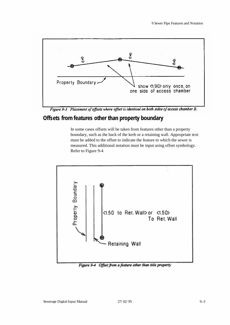
Sewerage Digital Input Manual 27/02/95 9.-3
9 Sewer Pipe Features and Notation
Offsets from features other than property boundary
In some cases offsets will be taken from features other than a property boundary, such as the back of the kerb or a retaining wall. Appropriate text must be added to the offset to indicate the feature to which the sewer is measured. This additional notation must be input using offset symbology. Refer to Figure 9-4
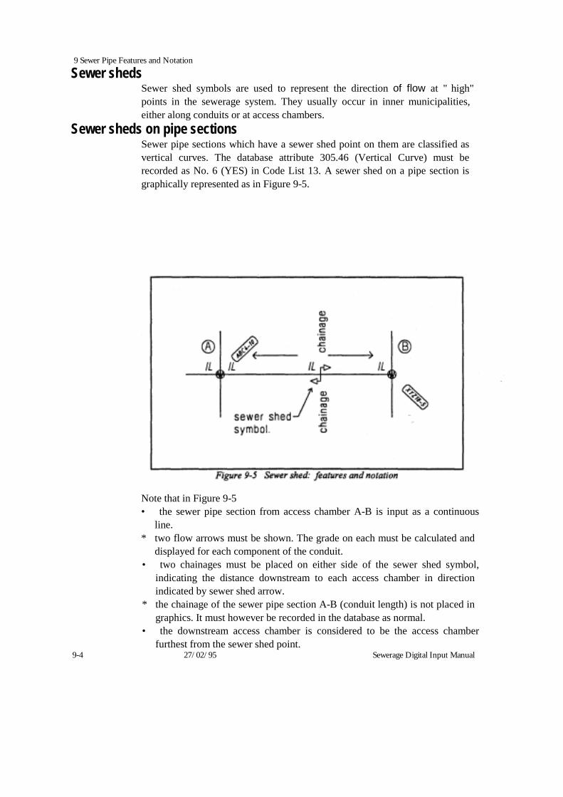
9 Sewer Pipe Features and Notation
Sewer sheds Sewer shed symbols are used to represent the direction of flow at "high" points in the sewerage system. They usually occur in inner municipalities, either along conduits or at access chambers.
Sewer sheds on pipe sections Sewer pipe sections which have a sewer shed point on them are classified as vertical curves. The database attribute 305.46 (Vertical Curve) must be recorded as No. 6 (YES) in Code List 13. A sewer shed on a pipe section is graphically represented as in Figure 9-5.
Note that in Figure 9-5 • the sewer pipe section from access chamber A-B is input as a continuous
line. * two flow arrows must be shown. The grade on each must be calculated and
displayed for each component of the conduit. • two chainages must be placed on either side of the sewer shed symbol,
indicating the distance downstream to each access chamber in direction indicated by sewer shed arrow.
* the chainage of the sewer pipe section A-B (conduit length) is not placed in graphics. It must however be recorded in the database as normal.
• the downstream access chamber is considered to be the access chamber furthest from the sewer shed point.
9-4 27/02/95 Sewerage Digital Input Manual


9 Sewer Pipe Features and Notation
Sewer sheds at access chambers
If a sewer shed occurs at an access chamber, place the symbol slightly to one side of the access chamber, making it clearly visible, as shown in Figure 9-6. In this case, no sewer shed chainage is required and access chamber chainages are displayed in graphics as normal.
Abandoned sewers
Where it has been determined that a sewerage pipe has been abandoned, ' the consultant must supply to the Water Company a hard copy plan detailing
the extent of abandonment. Demolished sewers
Where an abandoned sewer has been demolished or removed from the ground, the consultant must supply to the Water Company a hard copy plan detailing the extent of demolition.
Sewer renewals
Sewer pipe sections can be renewed by two methods:
relining replacement Sewerage Digital Input Manual 27/02/95 9-5

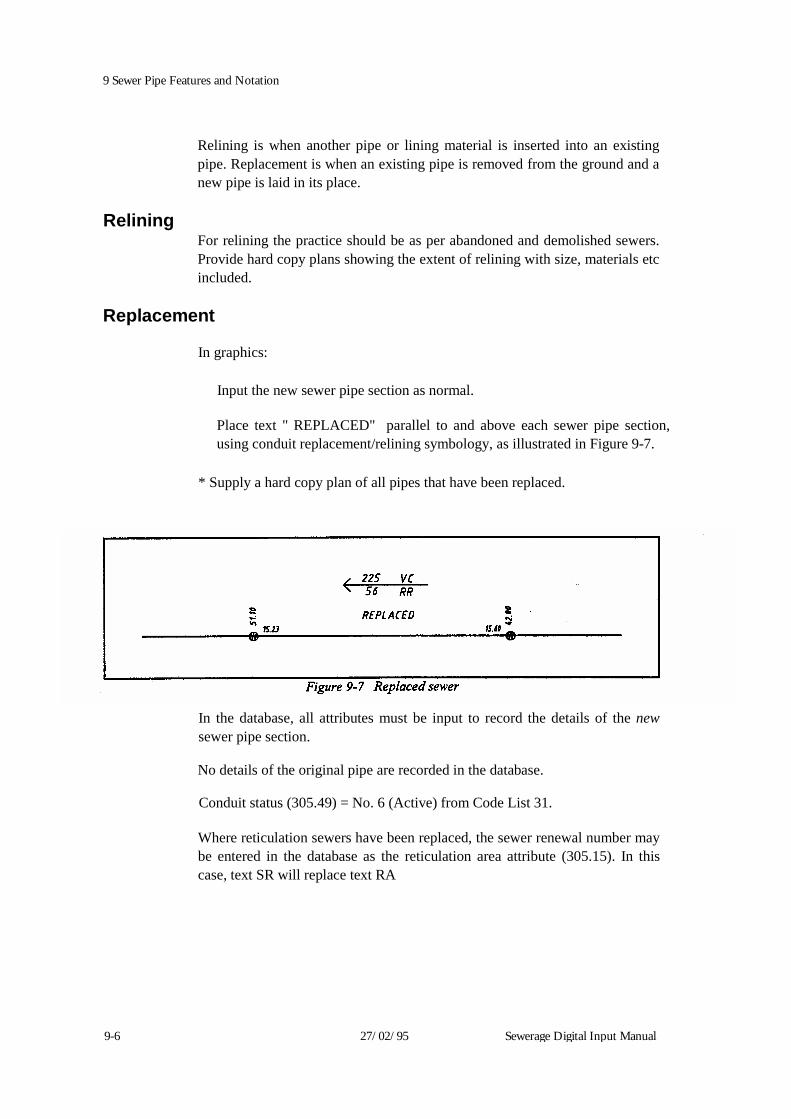
9-6 27/02/95 Sewerage Digital Input Manual
9 Sewer Pipe Features and Notation
Relining is when another pipe or lining material is inserted into an existing pipe. Replacement is when an existing pipe is removed from the ground and a new pipe is laid in its place.
Relining
For relining the practice should be as per abandoned and demolished sewers. Provide hard copy plans showing the extent of relining with size, materials etc included.
Replacement
In graphics:
Input the new sewer pipe section as normal.
Place text "REPLACED" parallel to and above each sewer pipe section, using conduit replacement/relining symbology, as illustrated in Figure 9-7.
* Supply a hard copy plan of all pipes that have been replaced.
In the database, all attributes must be input to record the details of the new sewer pipe section.
No details of the original pipe are recorded in the database. Conduit status (305.49) = No. 6 (Active) from Code List 31.
Where reticulation sewers have been replaced, the sewer renewal number may be entered in the database as the reticulation area attribute (305.15). In this case, text SR will replace text RA

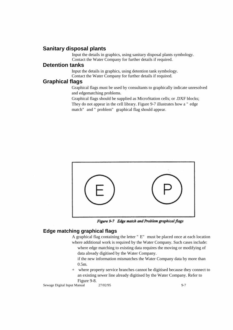
Sanitary disposal plantsInput the details in graphics, using sanitary disposal plants symbology. Contact the Water Company for further details if required.
Detention tanks Input the details in graphics, using detention tank symbology. Contact the Water Company for further details if required.
Graphical flags Graphical flags must be used by consultants to graphically indicate unresolved and edgematching problems. Graphical flags should be supplied as MicroStation cells; or .DXF blocks; They do not appear in the cell library. Figure 9-7 illustrates how a "edge match" and "problem" graphical flag should appear.
Edge matching graphical flagsA graphical flag containing the letter "E" must be placed once at each location where additional work is required by the Water Company. Such cases include:
where edge matching to existing data requires the moving or modifying of data already digitised by the Water Company. if the new information mismatches the Water Company data by more than 0.5m.
+ where property service branches cannot be digitised because they connect to an existing sewer line already digitised by the Water Company. Refer to Figure 9-8.
Sewage Digital Input Manual 27/02/95 9-7

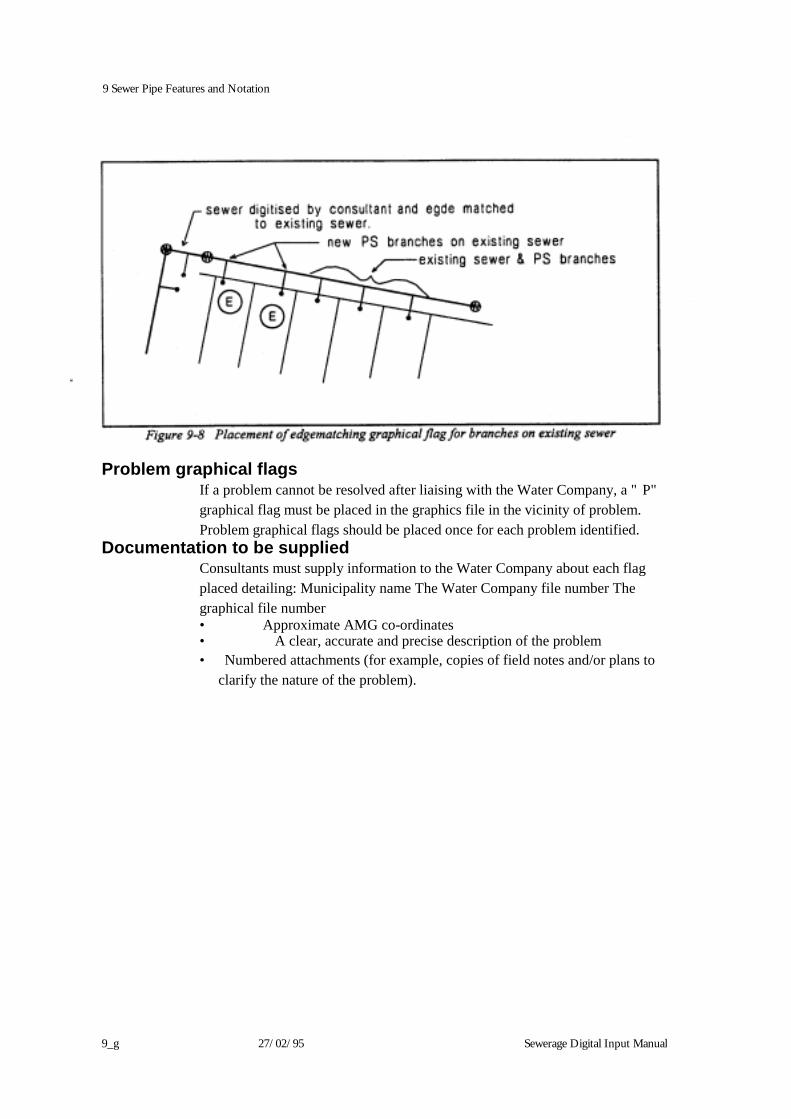
9 Sewer Pipe Features and Notation
9_g 27/02/95 Sewerage Digital Input Manual
Problem graphical flags If a problem cannot be resolved after liaising with the Water Company, a "P" graphical flag must be placed in the graphics file in the vicinity of problem. Problem graphical flags should be placed once for each problem identified.
Documentation to be supplied Consultants must supply information to the Water Company about each flag placed detailing: Municipality name The Water Company file number The graphical file number • Approximate AMG co-ordinates • A clear, accurate and precise description of the problem • Numbered attachments (for example, copies of field notes and/or plans to
clarify the nature of the problem).

Sewerage Digital Input Manual 17/07/2002 10–1
Chapter 10 Property Service Branches and Associated Features
This chapter describes the database and graphical requirements for the input of property service branches and associated features.
General Property service branches are pipes which connect the property service drains within a privately owned property to the Water Company’s sewer pipes.
Oblique branches (OBs) are short stub pipes located on sewer pipes to allow for the construction of property service branches at a later date. They should not be confused with oblique branches on property service spur branches.
The graphical difference between property service branches and oblique branches on sewer pipe sections is explained in Chapter 3. The Intergraph line type to be used for branches and OB’s (for MicroStation DGN) is specified in Table 3-1.
Property service branch conduits and oblique branch conduits must be input to:
✦ intersect exactly with the sewer pipe that owns them. Branches constructed out of access chambers are owned by the sewer immediately downstream, and must be included in the branch count for that sewer pipe section.
✦ show all bends (shown as a line string and not individual line segments).
10 Property Service Branches and Associated Features
10–2 17/07/2002 Sewerage Digital Input Manual
Database Property Service and Oblique Branches (entity 313) are owned by Sewer Pipe Sections (entity 305).
Branch count
The branch count (305.44) for a pipe section must include:
✦ all individual property branches,
✦ all spur branches including the branch which does not actually connect to the sewer,
✦ all property service branches and oblique branches out of the upstream access chamber.
Property service numbers
All property service branches and oblique branches constructed on a sewer line must have a unique property service number.
Property service numbers can be obtained from the Water Company.
Dummy property service numbers
In cases where more than one property service branch on a sewer have the same property service number, the existing number must be assigned to only one branch. Unique dummy property service numbers must be assigned to all other branches or OB’s servicing that property.
Dummy numbers must also be assigned to branches and OB’s on the sewer for which the Water Company property service number is not available.
The correlation between dummy and existing property service numbers must be recorded in a .PSL file. Refer to Chapter 1 for details.
Dummy property service numbers must be eight characters in length and assigned with a three letter prefix according to the name of the consultant (ie three letter prefix followed by five numbers. For example, the company “ACME Digitising Corporation” could assign all dummy property service numbers with the three letter prefix “ADC”. These numbers can only ever be used once.
The assignment of dummy property service numbers is shown in Figure 10-1.
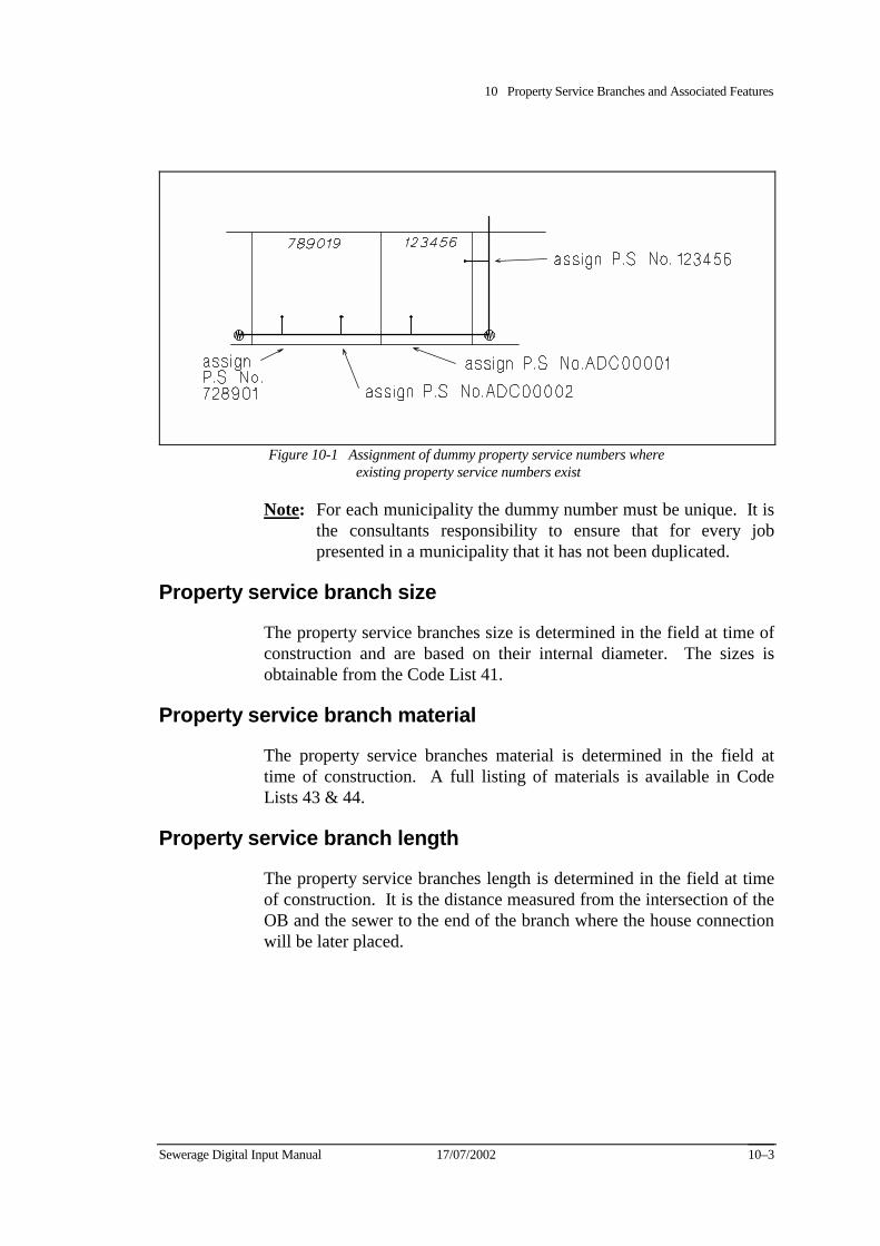
10 Property Service Branches and Associated Features
Sewerage Digital Input Manual 17/07/2002 10–3
Figure 10-1 Assignment of dummy property service numbers where existing property service numbers exist
Note: For each municipality the dummy number must be unique. It is the consultants responsibility to ensure that for every job presented in a municipality that it has not been duplicated.
Property service branch size
The property service branches size is determined in the field at time of construction and are based on their internal diameter. The sizes is obtainable from the Code List 41.
Property service branch material
The property service branches material is determined in the field at time of construction. A full listing of materials is available in Code Lists 43 & 44.
Property service branch length
The property service branches length is determined in the field at time of construction. It is the distance measured from the intersection of the OB and the sewer to the end of the branch where the house connection will be later placed.
10 Property Service Branches and Associated Features
10–4 17/07/2002 Sewerage Digital Input Manual
Property service branch type
The property service branch type descriptions in Code List 321 and 322 describe the configuration of the branch structure. The entries 22 to 32 inclusive relate to the current branch types. These are determined in the field at the time of construction.
Property service branch chainage
The distance from the downstream access chamber to the branch (attribute 313.20) is commonly referred to as the branch chainage.
The chainage of property service branches must be entered in the database as running chainages, measured from the downstream access chamber. For all branches constructed out of an upstream access chamber, the branch chainage must equal the conduit length (305.18).
Property Service branch surface level
The surface level is determined in the field at the time of construction. It is the natural surface level directly above the end of the property service branch.
Property Service branch invert level
The invert level of a property service is determined in the field at the time of construction. It is the AHD level of the end of the property service branch.
For type 2A branches it is the top of the pipe end. This will be cut at a later date when the plumber installs the house connection and the length of pipe cut off will have to be measured and supplied back to the Water Company to enable the invert level to be adjusted in the database and graphics.
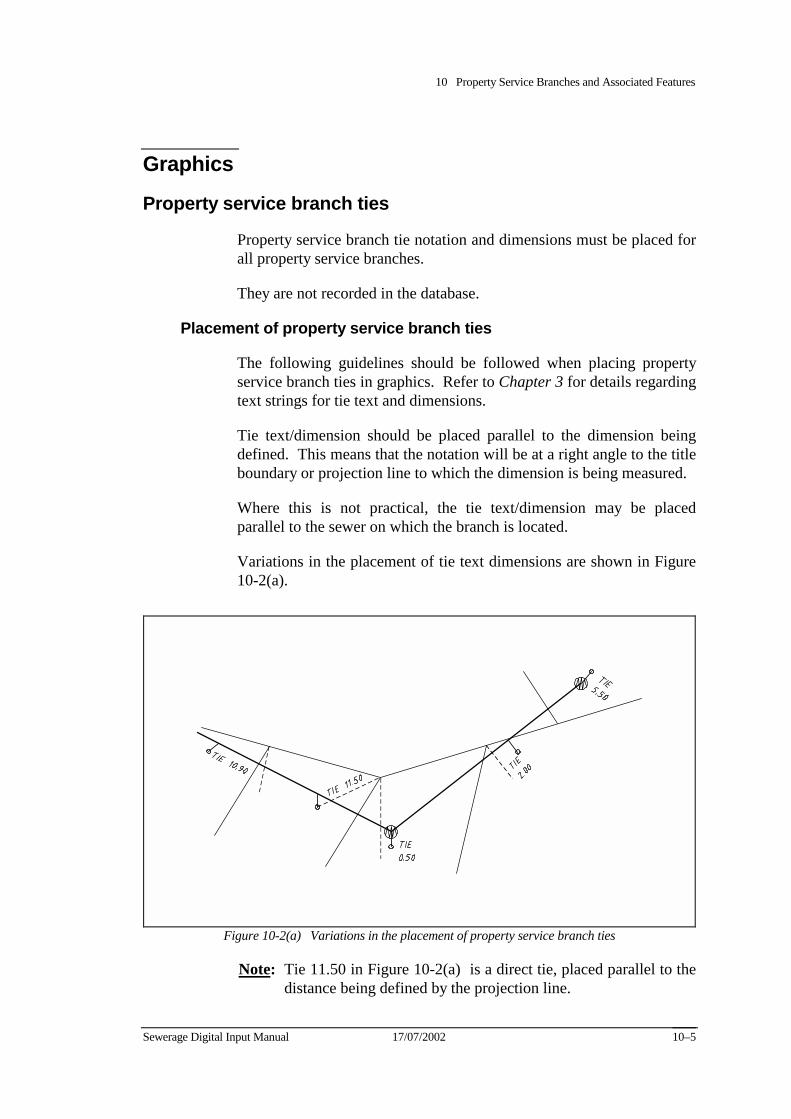
10 Property Service Branches and Associated Features
Sewerage Digital Input Manual 17/07/2002 10–5
Graphics
Property service branch ties
Property service branch tie notation and dimensions must be placed for all property service branches.
They are not recorded in the database.
Placement of property service branch ties
The following guidelines should be followed when placing property service branch ties in graphics. Refer to Chapter 3 for details regarding text strings for tie text and dimensions.
Tie text/dimension should be placed parallel to the dimension being defined. This means that the notation will be at a right angle to the title boundary or projection line to which the dimension is being measured.
Where this is not practical, the tie text/dimension may be placed parallel to the sewer on which the branch is located.
Variations in the placement of tie text dimensions are shown in Figure 10-2(a).
Figure 10-2(a) Variations in the placement of property service branch ties
Note: Tie 11.50 in Figure 10-2(a) is a direct tie, placed parallel to the distance being defined by the projection line.
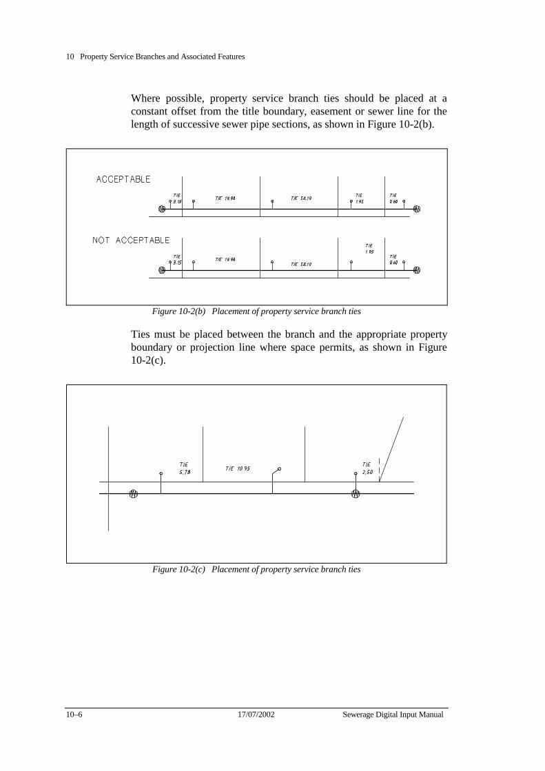
10 Property Service Branches and Associated Features
10–6 17/07/2002 Sewerage Digital Input Manual
Where possible, property service branch ties should be placed at a constant offset from the title boundary, easement or sewer line for the length of successive sewer pipe sections, as shown in Figure 10-2(b).
Figure 10-2(b) Placement of property service branch ties
Ties must be placed between the branch and the appropriate property boundary or projection line where space permits, as shown in Figure 10-2(c).
Figure 10-2(c) Placement of property service branch ties

10 Property Service Branches and Associated Features
Sewerage Digital Input Manual 17/07/2002 10–7
If space does not permit a tie to be placed between the branch and the appropriate title boundary or projection line, it should be placed adjacent to, but clear of the end of the branch, as shown in Figure 10-2(d)
Figure 10-2(d) Placement of property service branch ties
Ties must always be placed within the property of the branch to which they refer, as shown in Figure 10-2(e).
Figure 10-2(e) Placement of property service branch ties
If a branch has several ties associated with it, place all ties.
For extremely long distances, or to clarify obscure dimensions, a tie arrow may be used to indicate the title or feature from which the tie is measured. The tie notation may also be edited to clarify the distance being defined. Refer to Figure 10-2(f).
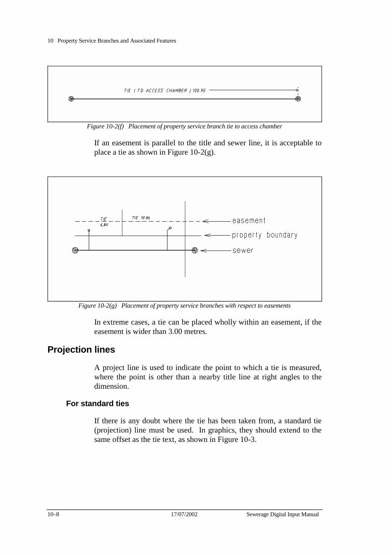
10 Property Service Branches and Associated Features
10–8 17/07/2002 Sewerage Digital Input Manual
Figure 10-2(f) Placement of property service branch tie to access chamber
If an easement is parallel to the title and sewer line, it is acceptable to place a tie as shown in Figure 10-2(g).
Figure 10-2(g) Placement of property service branches with respect to easements
In extreme cases, a tie can be placed wholly within an easement, if the easement is wider than 3.00 metres.
Projection lines
A project line is used to indicate the point to which a tie is measured, where the point is other than a nearby title line at right angles to the dimension.
For standard ties
If there is any doubt where the tie has been taken from, a standard tie (projection) line must be used. In graphics, they should extend to the same offset as the tie text, as shown in Figure 10-3.

10 Property Service Branches and Associated Features
Sewerage Digital Input Manual 17/07/2002 10–9
Figure 10-3 Projection lines for standard ties
For direct ties
Projection lines may be placed to indicate direct ties. That is, the distance between the end of a property service branch and a feature (for example, a access chamber or the corner of the title). In these cases, the tie should be placed on the same angle as the projection line as shown in Figure 10-4.
Figure 10-4 Projection line placement to define direct tie alignment
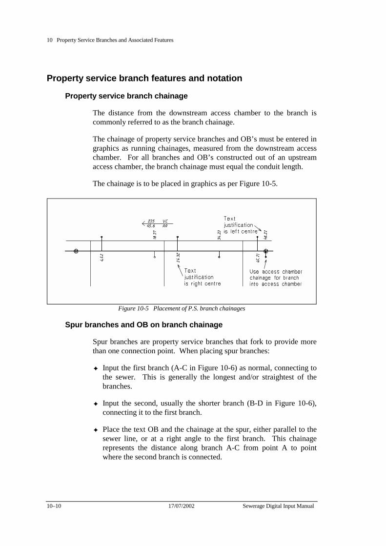
10 Property Service Branches and Associated Features
10–10 17/07/2002 Sewerage Digital Input Manual
Property service branch features and notation
Property service branch chainage
The distance from the downstream access chamber to the branch is commonly referred to as the branch chainage.
The chainage of property service branches and OB’s must be entered in graphics as running chainages, measured from the downstream access chamber. For all branches and OB’s constructed out of an upstream access chamber, the branch chainage must equal the conduit length.
The chainage is to be placed in graphics as per Figure 10-5.
Figure 10-5 Placement of P.S. branch chainages
Spur branches and OB on branch chainage
Spur branches are property service branches that fork to provide more than one connection point. When placing spur branches:
✦ Input the first branch (A-C in Figure 10-6) as normal, connecting to the sewer. This is generally the longest and/or straightest of the branches.
✦ Input the second, usually the shorter branch (B-D in Figure 10-6), connecting it to the first branch.
✦ Place the text OB and the chainage at the spur, either parallel to the sewer line, or at a right angle to the first branch. This chainage represents the distance along branch A-C from point A to point where the second branch is connected.
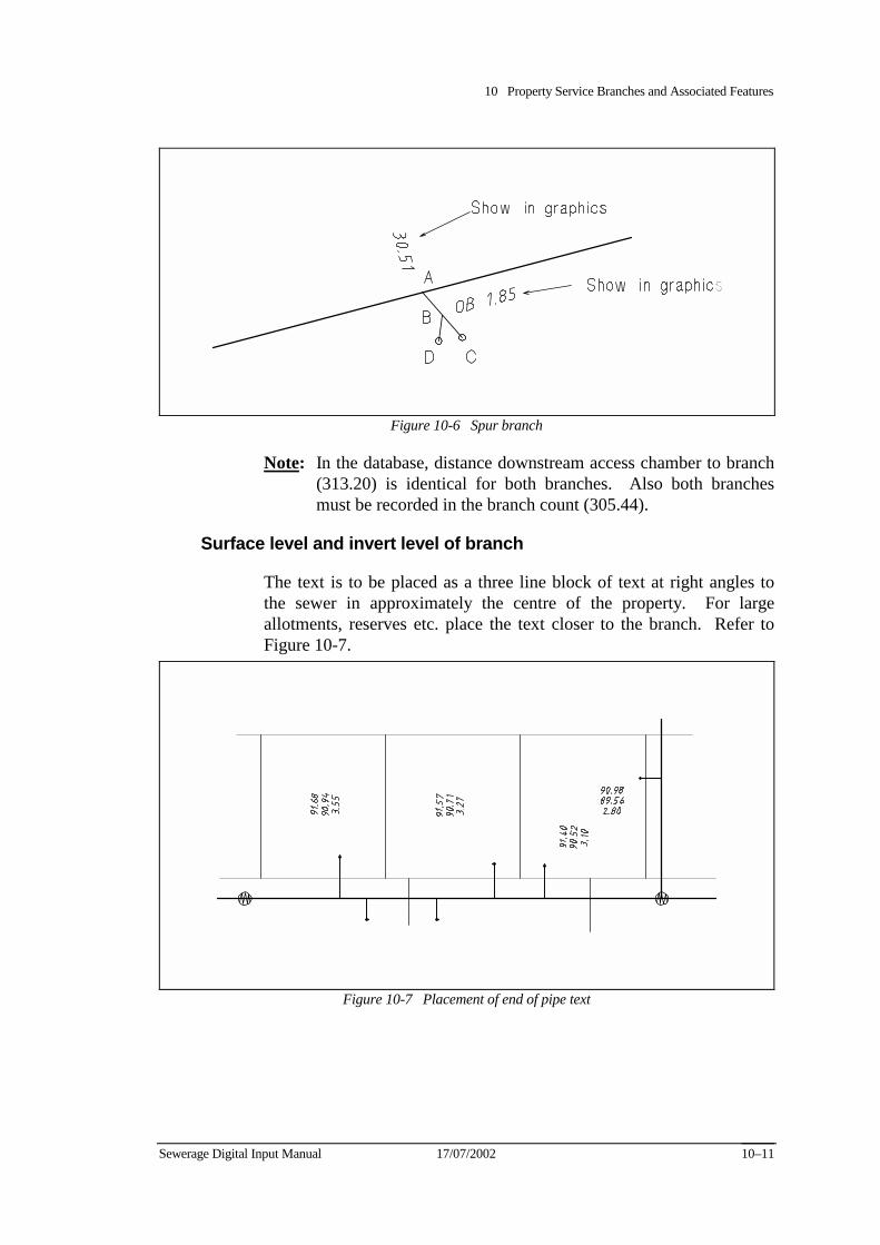
10 Property Service Branches and Associated Features
Sewerage Digital Input Manual 17/07/2002 10–11
Figure 10-6 Spur branch
Note: In the database, distance downstream access chamber to branch (313.20) is identical for both branches. Also both branches must be recorded in the branch count (305.44).
Surface level and invert level of branch
The text is to be placed as a three line block of text at right angles to the sewer in approximately the centre of the property. For large allotments, reserves etc. place the text closer to the branch. Refer to Figure 10-7.
Figure 10-7 Placement of end of pipe text
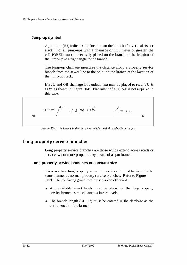
10 Property Service Branches and Associated Features
10–12 17/07/2002 Sewerage Digital Input Manual
Jump-up symbol
A jump-up (JU) indicates the location on the branch of a vertical rise or stack. For all jump-ups with a chainage of 1.00 meter or greater, the cell JORED must be centrally placed on the branch at the location of the jump-up at a right angle to the branch.
The jump-up chainage measures the distance along a property service branch from the sewer line to the point on the branch at the location of the jump-up stack.
If a JU and OB chainage is identical, text may be placed to read “JU & OB”, as shown in Figure 10-8. Placement of a JU cell is not required in this case.
Figure 10-8 Variations in the placement of identical JU and OB chainages
Long property service branches
Long property service branches are those which extend across roads or service two or more properties by means of a spur branch.
Long property service branches of constant size
These are true long property service branches and must be input in the same manner as normal property service branches. Refer to Figure 10-9. The following guidelines must also be observed:
✦ Any available invert levels must be placed on the long property service branch as miscellaneous invert levels.
✦ The branch length (313.17) must be entered in the database as the entire length of the branch.
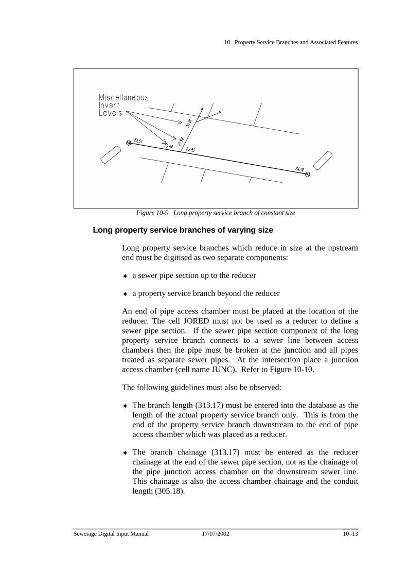
10 Property Service Branches and Associated Features
Sewerage Digital Input Manual 17/07/2002 10–13
Figure 10-9 Long property service branch of constant size
Long property service branches of varying size
Long property service branches which reduce in size at the upstream end must be digitised as two separate components:
✦ a sewer pipe section up to the reducer
✦ a property service branch beyond the reducer
An end of pipe access chamber must be placed at the location of the reducer. The cell JORED must not be used as a reducer to define a sewer pipe section. If the sewer pipe section component of the long property service branch connects to a sewer line between access chambers then the pipe must be broken at the junction and all pipes treated as separate sewer pipes. At the intersection place a junction access chamber (cell name JUNC). Refer to Figure 10-10.
The following guidelines must also be observed:
✦ The branch length (313.17) must be entered into the database as the length of the actual property service branch only. This is from the end of the property service branch downstream to the end of pipe access chamber which was placed as a reducer.
✦ The branch chainage (313.17) must be entered as the reducer chainage at the end of the sewer pipe section, not as the chainage of the pipe junction access chamber on the downstream sewer line. This chainage is also the access chamber chainage and the conduit length (305.18).
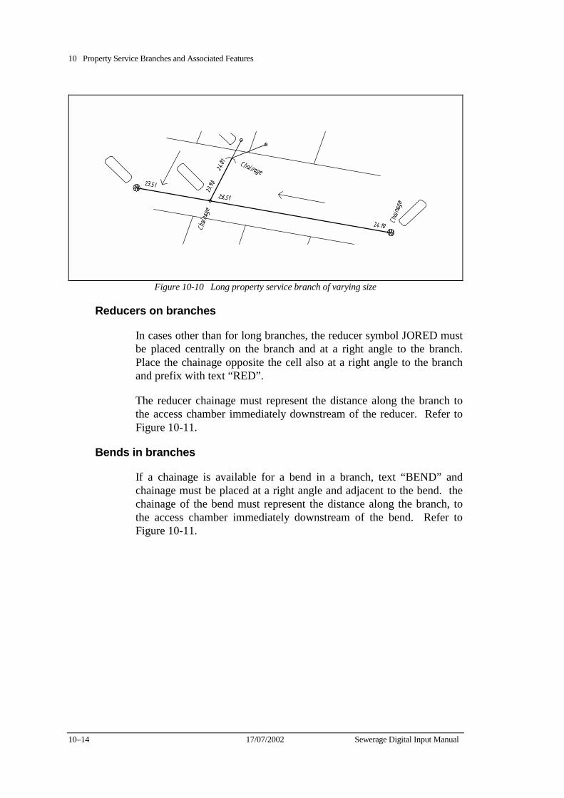
10 Property Service Branches and Associated Features
10–14 17/07/2002 Sewerage Digital Input Manual
Figure 10-10 Long property service branch of varying size
Reducers on branches
In cases other than for long branches, the reducer symbol JORED must be placed centrally on the branch and at a right angle to the branch. Place the chainage opposite the cell also at a right angle to the branch and prefix with text “RED”.
The reducer chainage must represent the distance along the branch to the access chamber immediately downstream of the reducer. Refer to Figure 10-11.
Bends in branches
If a chainage is available for a bend in a branch, text “BEND” and chainage must be placed at a right angle and adjacent to the bend. the chainage of the bend must represent the distance along the branch, to the access chamber immediately downstream of the bend. Refer to Figure 10-11.
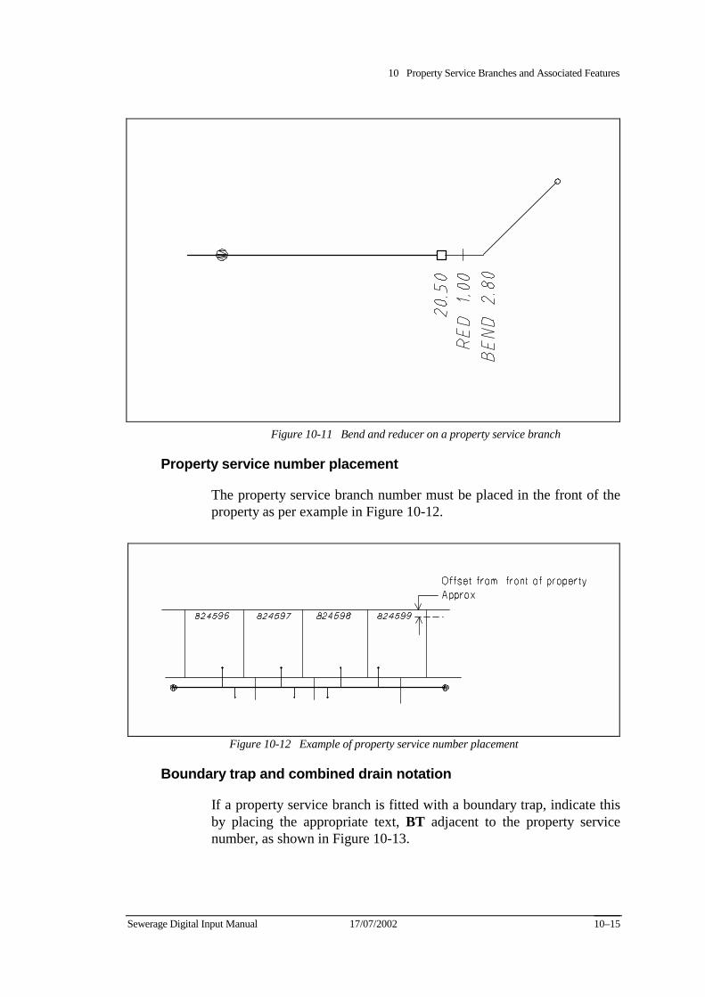
10 Property Service Branches and Associated Features
Sewerage Digital Input Manual 17/07/2002 10–15
Figure 10-11 Bend and reducer on a property service branch
Property service number placement
The property service branch number must be placed in the front of the property as per example in Figure 10-12.
Figure 10-12 Example of property service number placement
Boundary trap and combined drain notation
If a property service branch is fitted with a boundary trap, indicate this by placing the appropriate text, BT adjacent to the property service number, as shown in Figure 10-13.
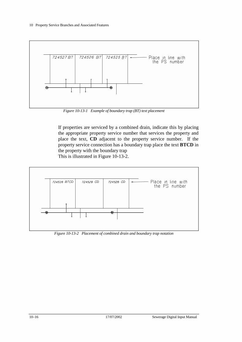
10 Property Service Branches and Associated Features
10–16 17/07/2002 Sewerage Digital Input Manual
Figure 10-13-1 Example of boundary trap (BT) text placement
If properties are serviced by a combined drain, indicate this by placing the appropriate property service number that services the property and place the text, CD adjacent to the property service number. If the property service connection has a boundary trap place the text BTCD in the property with the boundary trap This is illustrated in Figure 10-13-2.
Figure 10-13-2 Placement of combined drain and boundary trap notation
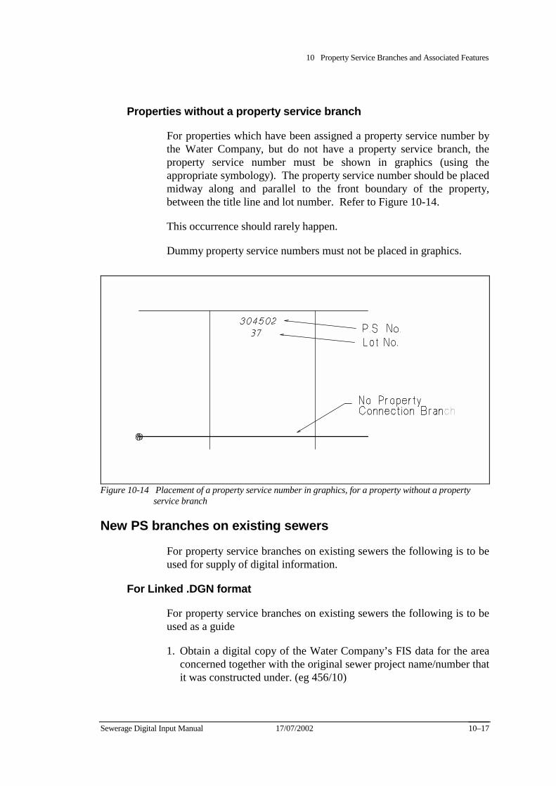
10 Property Service Branches and Associated Features
Sewerage Digital Input Manual 17/07/2002 10–17
Properties without a property service branch
For properties which have been assigned a property service number by the Water Company, but do not have a property service branch, the property service number must be shown in graphics (using the appropriate symbology). The property service number should be placed midway along and parallel to the front boundary of the property, between the title line and lot number. Refer to Figure 10-14.
This occurrence should rarely happen.
Dummy property service numbers must not be placed in graphics.
Figure 10-14 Placement of a property service number in graphics, for a property without a property service branch
New PS branches on existing sewers
For property service branches on existing sewers the following is to be used for supply of digital information.
For Linked .DGN format
For property service branches on existing sewers the following is to be used as a guide
1. Obtain a digital copy of the Water Company’s FIS data for the area concerned together with the original sewer project name/number that it was constructed under. (eg 456/10)
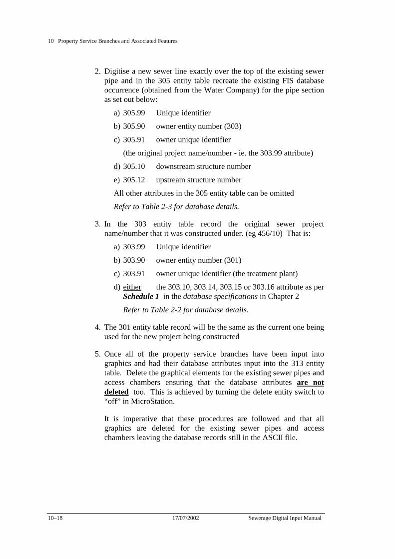
10 Property Service Branches and Associated Features
10–18 17/07/2002 Sewerage Digital Input Manual
2. Digitise a new sewer line exactly over the top of the existing sewer pipe and in the 305 entity table recreate the existing FIS database occurrence (obtained from the Water Company) for the pipe section as set out below:
a) 305.99 Unique identifier
b) 305.90 owner entity number (303)
c) 305.91 owner unique identifier
(the original project name/number - ie. the 303.99 attribute)
d) 305.10 downstream structure number
e) 305.12 upstream structure number
All other attributes in the 305 entity table can be omitted
Refer to Table 2-3 for database details.
3. In the 303 entity table record the original sewer project name/number that it was constructed under. (eg 456/10) That is:
a) 303.99 Unique identifier
b) 303.90 owner entity number (301)
c) 303.91 owner unique identifier (the treatment plant)
d) either the 303.10, 303.14, 303.15 or 303.16 attribute as per Schedule 1 in the database specifications in Chapter 2
Refer to Table 2-2 for database details.
4. The 301 entity table record will be the same as the current one being used for the new project being constructed
5. Once all of the property service branches have been input into graphics and had their database attributes input into the 313 entity table. Delete the graphical elements for the existing sewer pipes and access chambers ensuring that the database attributes are not deleted too. This is achieved by turning the delete entity switch to “off” in MicroStation.
It is imperative that these procedures are followed and that all graphics are deleted for the existing sewer pipes and access chambers leaving the database records still in the ASCII file.
10 Property Service Branches and Associated Features
Sewerage Digital Input Manual 17/07/2002 10–19
The Water Company’s translator will successfully input these branches into the FIS if these procedures are used. If they are not the translator will fail resulting in a rejection of the data and a possible non conformance being issued.
For Unlinked MicroStation .DGN and .DXF formats
The additional branches cannot be provided to the Water Company via the means set out above.
The consultant must provide the information relating to these branches in hard copy format in the form of field notes.
If the information relating to these branches is included in the ASCII files it will result in a failure to process through the Consulcad translator resulting in a rejection of the data and a possible non conformance being issued.
The graphics elements may be supplied in the graphics file as long as there is no database information relating to them in the ASCII file.
Documentation must be supplied drawing the Water Company to the attention of these particular type of branches being constructed on existing sewers.

10 Property Service Branches and Associated Features
10–20 17/07/2002 Sewerage Digital Input Manual
Sewerage Digital Input Manual 17/07/2002 11–1
Chapter 11 Private and Other Authority Sewers This chapter covers the requirements for the graphical input of private and other authority sewerage assets.
All features associated with sewerage works not owned by the Water Company must be input in the same manner as normal sewerage assets, but in graphics only. Elements relating to private or other authority sewers must have no link to the database.
Numbering of access chambers Although only graphical representations, access chambers must be assigned unique numbers in the manner described in Chapter 7. The numbering of access chambers for private and other authority pumping stations is as follows:
✦ Private sewerage pumping stations must be designated a two part unique access chamber number based on the municipality in which they are located.
The number must take the form:
PPSmn-No.
Where:
− PPS = Private Pumping Station abbreviation
− mn = Municipal Number (from Code List 15 and 17)
− No. = Number of pumping station, to be assigned on an incremental basis.
Therefore, the private sewerage pumping stations in Werribee would be numbered PPS42-01, PPS42-02 and so on.
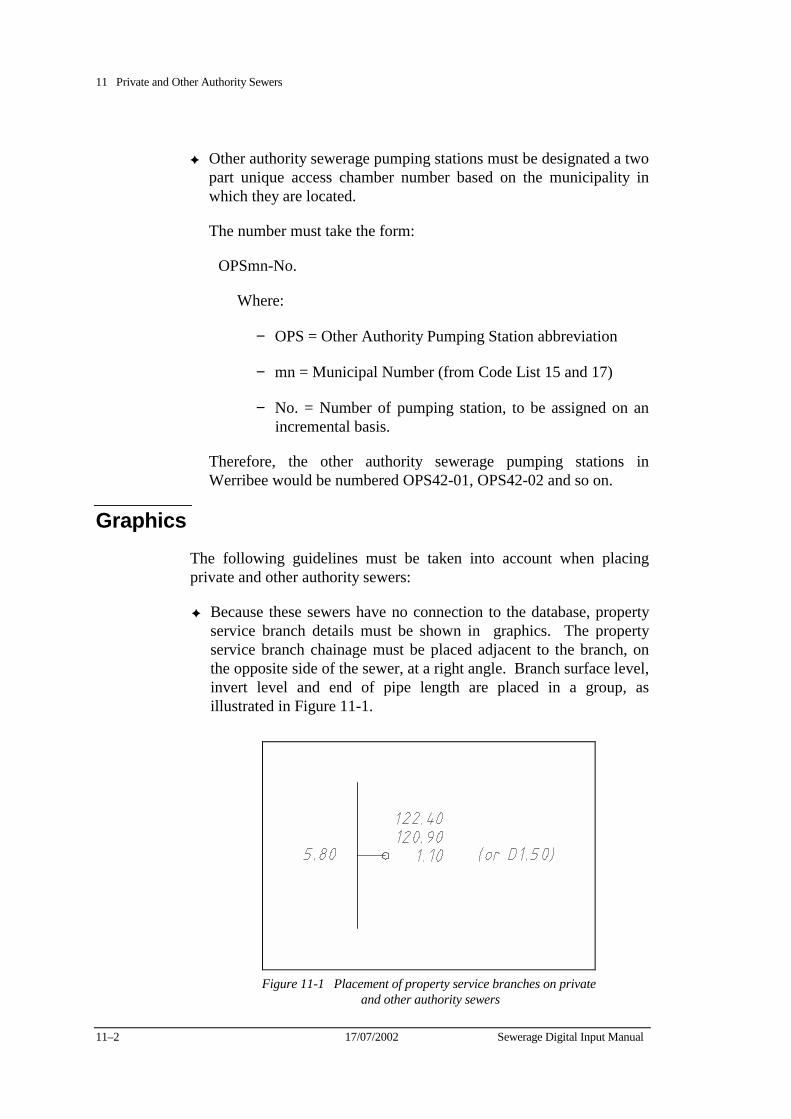
11 Private and Other Authority Sewers
11–2 17/07/2002 Sewerage Digital Input Manual
✦ Other authority sewerage pumping stations must be designated a two part unique access chamber number based on the municipality in which they are located.
The number must take the form:
OPSmn-No.
Where:
− OPS = Other Authority Pumping Station abbreviation
− mn = Municipal Number (from Code List 15 and 17)
− No. = Number of pumping station, to be assigned on an incremental basis.
Therefore, the other authority sewerage pumping stations in Werribee would be numbered OPS42-01, OPS42-02 and so on.
Graphics The following guidelines must be taken into account when placing private and other authority sewers:
✦ Because these sewers have no connection to the database, property service branch details must be shown in graphics. The property service branch chainage must be placed adjacent to the branch, on the opposite side of the sewer, at a right angle. Branch surface level, invert level and end of pipe length are placed in a group, as illustrated in Figure 11-1.
Figure 11-1 Placement of property service branches on private
and other authority sewers
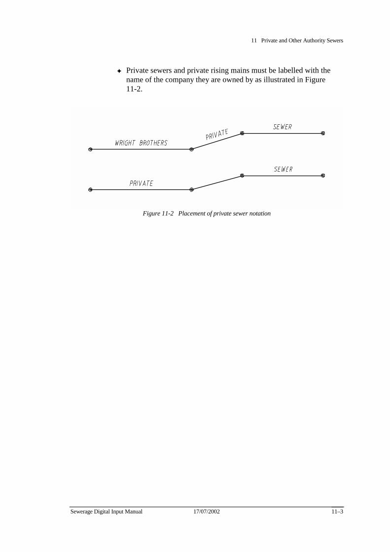
11 Private and Other Authority Sewers
Sewerage Digital Input Manual 17/07/2002 11–3
✦ Private sewers and private rising mains must be labelled with the name of the company they are owned by as illustrated in Figure 11-2.
Figure 11-2 Placement of private sewer notation

11 Private and Other Authority Sewers
11–4 17/07/2002 Sewerage Digital Input Manual
Sewerage Digital Input Manual 17/07/2002 12-1
Chapter 12 Glossary of Terms
access chamber
A feature on the sewerage system which allows inspection of and/or access to the sewerage system. Access chambers are used to define sewer pipe sections via their upstream and downstream numbers. See entries under standard access chamber, intermediate access chamber, sewerage pumping station access chamber and emergency relief structure.
access chamber chainage
The distance between one numbered access chamber and the next numbered access chamber immediately downstream. Also referred to as the conduit length of the sewer pipe section.
access point
refer access chamber
attribute
A database field (column) under which details are stored about a particular entity.
branch tie
A measurement which specifies the location of the end of a property service branch, usually measured from the corner of a property or a fixed feature.
cell
A combination of elements which form a standard graphical symbol for the representation of a feature. Cells are able to be manipulated as a single element. The cell origin is the point at which a cell is placed, usually at the centre if the cell is symmetrical.
code list
A list of numbered item descriptions which describe particular attribute values in standard terminology. Code list entry numbers are entered in the database as attribute values for particular items.
12 Glossary of Terms
12-2 17/07/2002 Sewerage Digital Input Manual
curved sewer
A sewer pipe section which contains horizontal and/or vertical changes of alignment such as curves, bends or changes of grade.
database file
An ASCII format file with an extension containing the database records of the attributes for a particular entity. One file is required for each entity in each municipality.
database schedule
A listing of all entities and associated attributes for which the Water Company requires valid database records. The schedule includes details of formats, default values and user notes for each attribute. In this document, the database schedule is referred to as “the database”.
default value
A database entry input when a value cannot be determined from source documents.
downstream
The end of a pipeline to which sewage flows by gravity or is pumped. For gravity sewers, the downstream end is usually lower than the upstream end. For rising mains, the downstream end is usually higher than the upstream end. Also see upstream.
dummy property service number
A unique number which must be assigned by consultants to property service branches on sewer lines when a the Water Company assigned number is not available, or a single the Water Company number relates to multiple branches. Also see property service number.
edgematching
The process of connecting new pipe sections to previously digitised data.
element
A basic graphical item. For example, a line, circle or arc.
12 Glossary of Terms
Sewerage Digital Input Manual 17/07/2002 12-3
emergency relief structure (ERS)
A system of sewer pipe sections and/or access chambers designed to control sewage overflow during peak wet weather flow or the failure of pumping stations. Each emergency relief structure includes a specially designed access chamber - the ERS access chamber.
entity
A database table consisting of attributes (columns) and occurrences (rows).
flow arrow
The graphical pointer which indicates the overall direction of flow of sewage along a sewer pipe section, as determined by gravity or pumping. Data displayed on the flow arrow indicates the size, grade, material and joint packing of the sewer pipe section to which it relates.
grade
The slope (or gradient) of a pipe. Grade is calculated from the conduit length and the difference between the upstream and downstream invert levels.
graphical flags
Symbols placed in graphics files by consultants to indicate locations where further action is required by the Water Company.
gravity sewer
A sewer pipe section through which the sewage flows under the influence of gravity.
horizontal curve
Any change of direction in the horizontal alignment of a sewer pipe section. Horizontal curves include bends and smooth curves of constant or varied radius.
independent sewer
A sewer which connects to the immediate downstream sewer by way of an end of pipe or pipe junction access chamber. They typically occur where a sewer line has been extended on the same alignment, or where a change of size, material or status has occurred.
12 Glossary of Terms
12-4 17/07/2002 Sewerage Digital Input Manual
intermediate access chamber
An access chamber is intermediate when it is located between standard access chambers, and there is no change of conduit size, grade, material, level or project at that point. Intermediate access chambers are not numbered and do not require database attributes.
invert level
The level (to Australian Height Datum) of a point on the inside bottom of a pipe.
level structure
A listing of the levels to which all items must be assigned in graphics files.
manhole
Refer to access chamber
municipal index file
Graphics file showing the geographic division of and numbering of municipalities. The boundary lines define the placement of graphics data in each digital file.
named sewer
Named sewers from the basis of gravity sewerage systems. All sewer pipes of 300 mm diam. and greater are classified as named sewers. Some pipes of less than 300 mm diam. are also classified as named sewers, as defined by the Water Company. Most named sewers are branch sewers or main sewers.
occurrence
A database field (row) which records an entities attribute.
offset
A measurement that specifies the location of a pipe line, usually measured at a right angle from a property boundary.
other authority sewer
A sewer and its associated features which is owned and operated by an authority other than the Water Company which may or may not outlet to the Water Company sewerage system.

12 Glossary of Terms
Sewerage Digital Input Manual 17/07/2002 12-5
outfall access chamber
The access chamber, usually at the downstream end of a rising main.
precast access chamber
A manufactured access chamber, usually circular.
private sewer
A sewer and its associated features which is owned and operated by a private company which may or may not outlet to the Water Company sewerage system. Also see other authority sewer.
property service branch
Pipes which connect the property service drains within a privately owned property to the Water Company’s sewer pipes.
property service list file
An ASCII format file with the extension .PSL containing a list of dummy property service numbers and the corresponding Water Company property service numbers. One file is required for each municipality. Also see dummy property service number.
property service number
A unique number assigned by the Water Company to each property served by the sewerage system. They serve as reference numbers for records about the property service branch, property service drains and fittings within the property. Also see dummy property service number.
property service oblique branch
Short “stub” pipes on sewer pipes which allow for the future construction of property service branches. Also referred to as OB’s. These are graphics only elements with no database information.
pumping station access chamber
An access chamber structure containing sewerage pumping equipment. Sewerage pumping stations vertically lift sewage and either convey it under pressure to another point in the sewerage system, or discharge it at a higher level into the gravity sewer immediately downstream.
12 Glossary of Terms
12-6 17/07/2002 Sewerage Digital Input Manual
reticulation area / reticulation extension projects
Particular types of sewer projects consisting of sewers of less than 300mm diameter. Reticulation area numbers are prefixed by text “RA” and reticulation extension numbers are prefixed with text “RE”.
reticulation sewer
A gravity sewer pipe of less than 300 mm diameter. Reticulation area and reticulation extension projects may only consist of reticulation sewers.
rising main
A sewer pipe section through which sewage is pumped, usually in an uphill direction.
running chainage
A chainage which increments along the length of a sewer pipe section between two numbered access chambers. The downstream access chamber is assigned a datum chainage of zero. The zero is not shown in graphics.
sewage
The effluent (waste water) conveyed by sewer pipes.
sewerage
The system of sewer pipes, access chambers and structures that collect and convey sewage from individual properties to treatment plants for purification.
sewerage project
The scheme under which the sewers of a particular area are planned, designed and constructed. Types of sewer projects include named sewers, reticulation areas and reticulation extensions. All sewerage projects are individually numbered.
sewerage treatment (purification) plant
In this manual, the terms sewerage treatment plant and purification plants are considered to be the same. They refer to a complex to which sewage is conveyed by the sewerage system and treated. In the database, sewerage treatment plants “own” all other entities.
12 Glossary of Terms
Sewerage Digital Input Manual 17/07/2002 12-7
sewer pipe section
A length of sewer pipe (conduit) between two numbered access chambers. Sewer pipe sections are graphically input as continuous elements - lines, strings or curves.
siphon
A vertically curved sewer, the invert levels of which are designed so that sewage is able to be conveyed under features such as natural watercourses and man made drains.
This is achieved by the hydraulic design of the system, which causes sewage to be siphoned between inlet and outlet access chambers.
standard access chamber
Access chambers which derive their symbology from the size range of the sewer pipe section immediately downstream. Standard access chambers must be uniquely numbered and entered with full database attributes. Also see intermediate access chamber.
symbol
See cell.
symbology
The specifications describing the way in which elements must appear in graphics files. Symbology defines the element class, element type, level, colour, weight, line style, text criteria (font, height, width, justification) and cell requirements for each graphics item.
tie
See branch tie.
upstream
The end of a pipeline from which sewage flows by gravity, or is pumped. For gravity sewers, the upstream end is usually higher than the downstream end. For rising mains, the upstream end is usually lower than the downstream end. Also see downstream.
12 Glossary of Terms
12-8 17/07/2002 Sewerage Digital Input Manual
vertical curve
Any change of direction in the vertical alignment of a sewer pipe section. Vertical curves include changes of grade and smooth curves of constant or varied radius.

Appendices

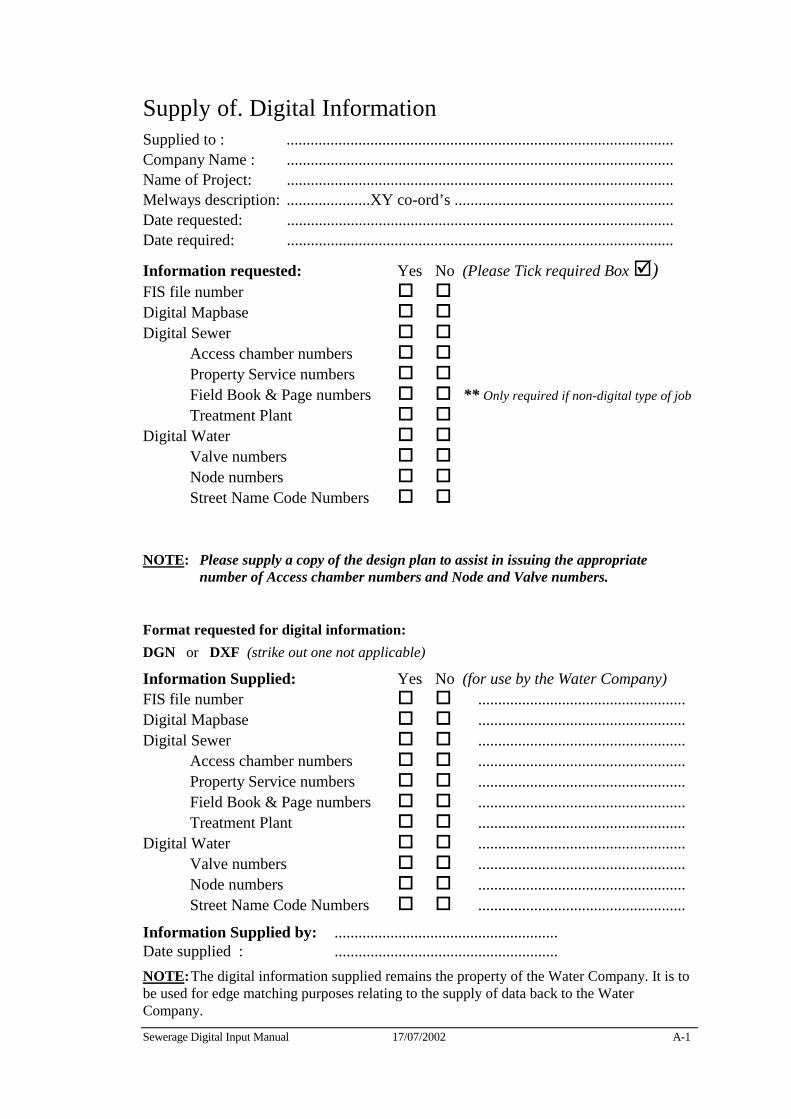
Sewerage Digital Input Manual 17/07/2002 A-1
Supply of. Digital Information Supplied to : ................................................................................................. Company Name : ................................................................................................. Name of Project: ................................................................................................. Melways description: .....................XY co-ord’s ....................................................... Date requested: ................................................................................................. Date required: .................................................................................................
Information requested: Yes No (Please Tick required Box !) FIS file number " " Digital Mapbase " " Digital Sewer " " Access chamber numbers " " Property Service numbers " " Field Book & Page numbers " " ** Only required if non-digital type of job Treatment Plant " " Digital Water " " Valve numbers " " Node numbers " " Street Name Code Numbers " "
NOTE: Please supply a copy of the design plan to assist in issuing the appropriate number of Access chamber numbers and Node and Valve numbers.
Format requested for digital information: DGN or DXF (strike out one not applicable)
Information Supplied: Yes No (for use by the Water Company) FIS file number " " .................................................... Digital Mapbase " " .................................................... Digital Sewer " " .................................................... Access chamber numbers " " .................................................... Property Service numbers " " .................................................... Field Book & Page numbers " " .................................................... Treatment Plant " " .................................................... Digital Water " " .................................................... Valve numbers " " .................................................... Node numbers " " .................................................... Street Name Code Numbers " " ....................................................
Information Supplied by: ........................................................ Date supplied : ........................................................ NOTE: The digital information supplied remains the property of the Water Company. It is to be used for edge matching purposes relating to the supply of data back to the Water Company.

A-2 17/07/02 Sewerage Digital Input Manual
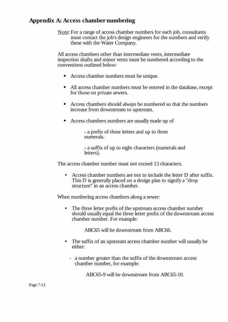
Appendix A: Access chamber numbering
Note: For a range of access chamber numbers for each job, consultants must contact the job's design engineers for the numbers and verify these with the Water Company.
All access chambers other than intermediate vents, intermediate inspection shafts and minor vents must be numbered according to the conventions outlined below:
! Access chamber numbers must be unique.
! All access chamber numbers must be entered in the database, except
for those on private sewers.
! Access chambers should always be numbered so that the numbers increase from downstream to upstream.
! Access chambers numbers are usually made up of
- a prefix of three letters and up to three numerals.
- a suffix of up to eight characters (numerals and letters).
The access chamber number must not exceed 13 characters.
• Access chamber numbers are not to include the letter D after suffix.
This D is generally placed on a design plan to signify a "drop structure" in an access chamber.
When numbering access chambers along a sewer:
• The three letter prefix of the upstream access chamber number
should usually equal the three letter prefix of the downstream access chamber number. For example:
ABC65 will be downstream from ABC66.
• The suffix of an upstream access chamber number will usually be
either:
- a number greater than the suffix of the downstream access chamber number, for example:
ABC65-9 will be downstream from ABC65-10.
Page 7-13
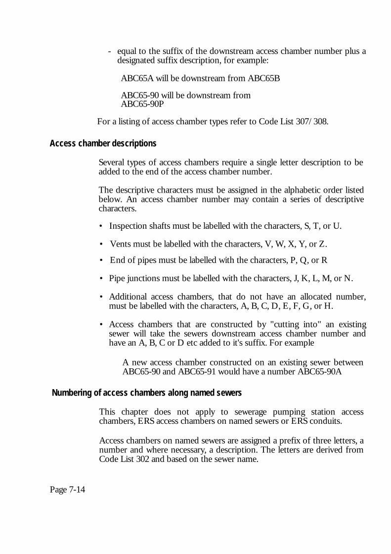
- equal to the suffix of the downstream access chamber number plus a designated suffix description, for example:
ABC65A will be downstream from ABC65B ABC65-90 will be downstream from ABC65-90P
For a listing of access chamber types refer to Code List 307/308. Access chamber descriptions
Several types of access chambers require a single letter description to be added to the end of the access chamber number. The descriptive characters must be assigned in the alphabetic order listed below. An access chamber number may contain a series of descriptive characters. • Inspection shafts must be labelled with the characters, S, T, or U. • Vents must be labelled with the characters, V, W, X, Y, or Z. • End of pipes must be labelled with the characters, P, Q, or R • Pipe junctions must be labelled with the characters, J, K, L, M, or N. • Additional access chambers, that do not have an allocated number,
must be labelled with the characters, A, B, C, D, E, F, G, or H. • Access chambers that are constructed by "cutting into" an existing
sewer will take the sewers downstream access chamber number and have an A, B, C or D etc added to it's suffix. For example
A new access chamber constructed on an existing sewer between ABC65-90 and ABC65-91 would have a number ABC65-90A
Numbering of access chambers along named sewers
This chapter does not apply to sewerage pumping station access chambers, ERS access chambers on named sewers or ERS conduits.
Access chambers on named sewers are assigned a prefix of three letters, a number and where necessary, a description. The letters are derived from Code List 302 and based on the sewer name.
Page 7-14
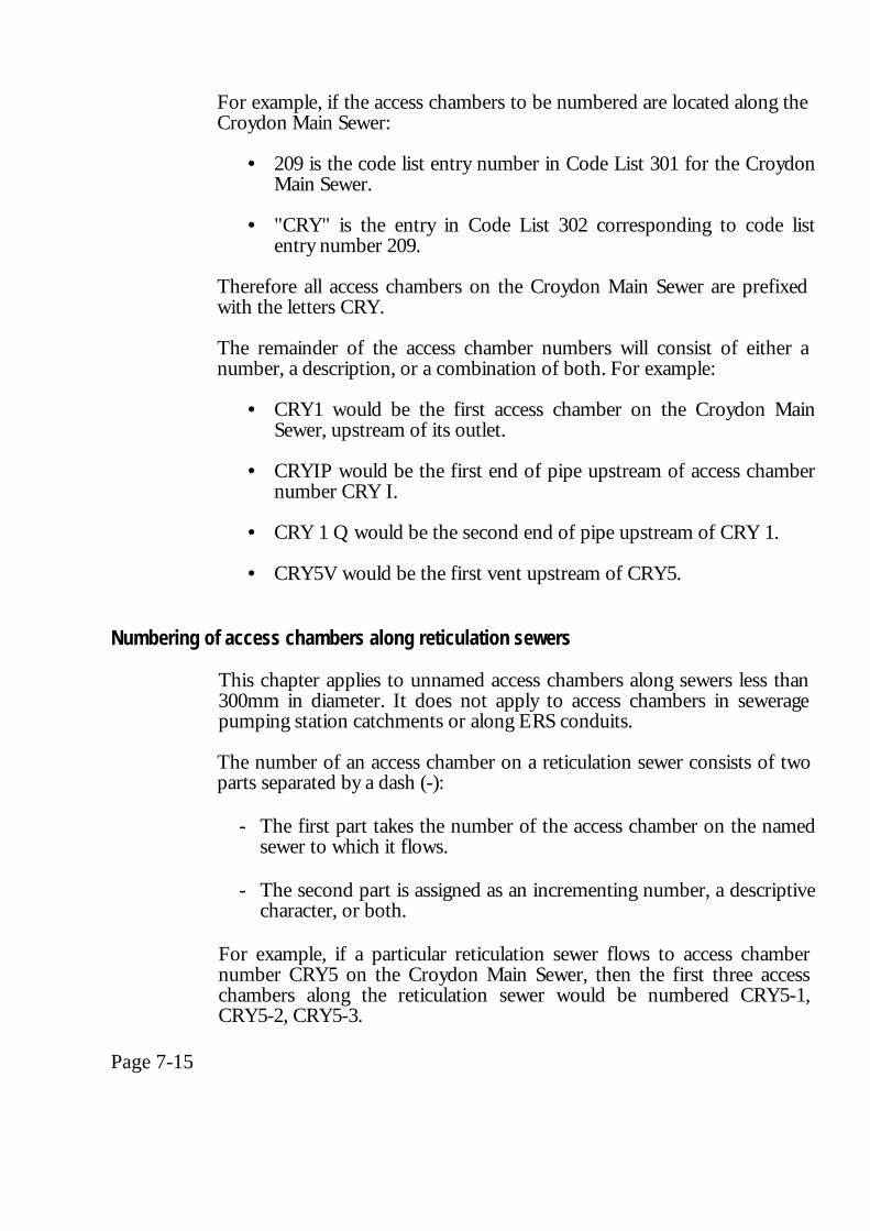
For example, if the access chambers to be numbered are located along the Croydon Main Sewer:
• 209 is the code list entry number in Code List 301 for the Croydon Main Sewer.
• "CRY" is the entry in Code List 302 corresponding to code list
entry number 209. Therefore all access chambers on the Croydon Main Sewer are prefixed with the letters CRY. The remainder of the access chamber numbers will consist of either a number, a description, or a combination of both. For example:
• CRY1 would be the first access chamber on the Croydon Main Sewer, upstream of its outlet.
• CRYIP would be the first end of pipe upstream of access chamber
number CRY I.
• CRY 1 Q would be the second end of pipe upstream of CRY 1.
• CRY5V would be the first vent upstream of CRY5.
Numbering of access chambers along reticulation sewers
This chapter applies to unnamed access chambers along sewers less than 300mm in diameter. It does not apply to access chambers in sewerage pumping station catchments or along ERS conduits. The number of an access chamber on a reticulation sewer consists of two parts separated by a dash (-):
- The first part takes the number of the access chamber on the named
sewer to which it flows.
- The second part is assigned as an incrementing number, a descriptive character, or both.
For example, if a particular reticulation sewer flows to access chamber number CRY5 on the Croydon Main Sewer, then the first three access chambers along the reticulation sewer would be numbered CRY5-1, CRY5-2, CRY5-3.
Page 7-15
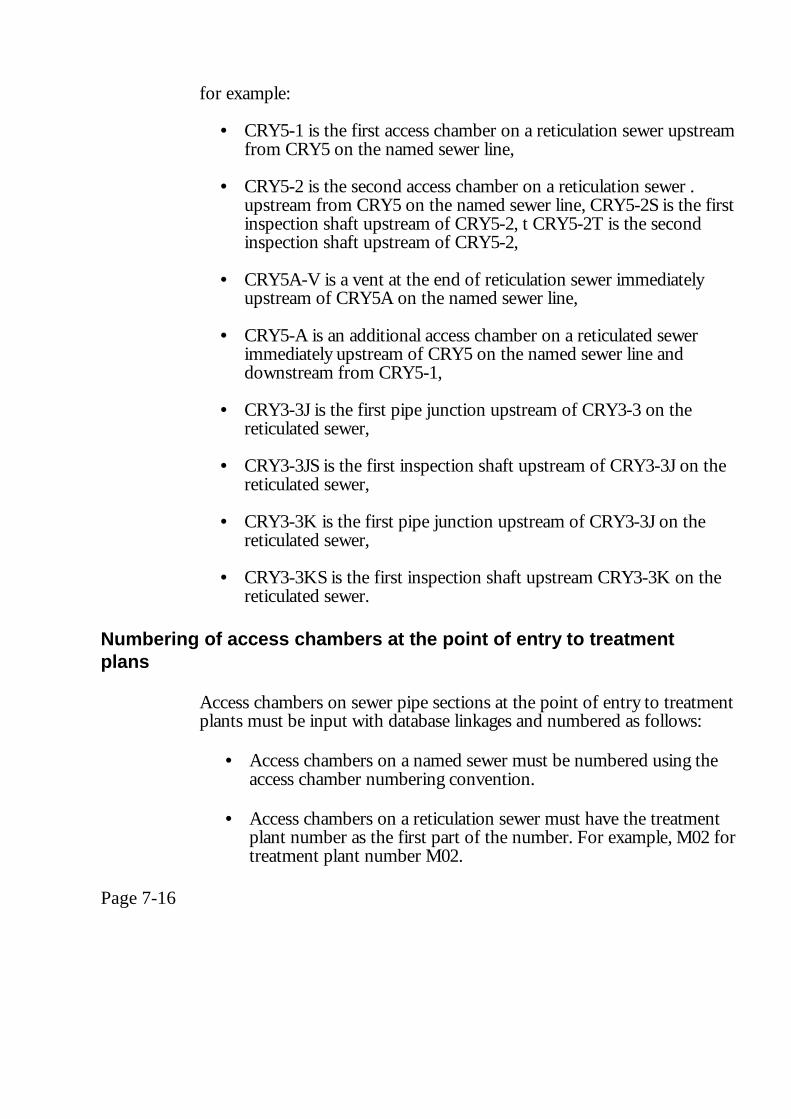
for example:
• CRY5-1 is the first access chamber on a reticulation sewer upstream from CRY5 on the named sewer line,
• CRY5-2 is the second access chamber on a reticulation sewer .
upstream from CRY5 on the named sewer line, CRY5-2S is the first inspection shaft upstream of CRY5-2, t CRY5-2T is the second inspection shaft upstream of CRY5-2,
• CRY5A-V is a vent at the end of reticulation sewer immediately
upstream of CRY5A on the named sewer line,
• CRY5-A is an additional access chamber on a reticulated sewer immediately upstream of CRY5 on the named sewer line and downstream from CRY5-1,
• CRY3-3J is the first pipe junction upstream of CRY3-3 on the
reticulated sewer,
• CRY3-3JS is the first inspection shaft upstream of CRY3-3J on the reticulated sewer,
• CRY3-3K is the first pipe junction upstream of CRY3-3J on the
reticulated sewer,
• CRY3-3KS is the first inspection shaft upstream CRY3-3K on the reticulated sewer.
Numbering of access chambers at the point of entry to treatment plans
Access chambers on sewer pipe sections at the point of entry to treatment plants must be input with database linkages and numbered as follows:
• Access chambers on a named sewer must be numbered using the
access chamber numbering convention.
• Access chambers on a reticulation sewer must have the treatment plant number as the first part of the number. For example, M02 for treatment plant number M02.
Page 7-16
• Pumping station access chambers must have the prefix TPS and the
treatment plant number as the first part of the number. For example, TPSM02 for treatment plant number M02.
Refer to Figure 7-14. Numbering of access chambers upstream of treatment plants
The numbering of access chambers on named sewers upstream of treatment plants is unaffected by the treatment plant number. Access chambers on reticulation sewers upstream of treatment plants must be assigned the appropriate prefix. The first part of this number is based on the number of the access chamber at the point of entry to the treatment plant. The suffixes of subsequent access chambers are numbered in the usual manner for reticulation sewers. Fore example:
• TPSM02-1 is the first access chamber upstream of TPSM02 on a reticulation sewer which enters treatment plant number M02 at a pumping station.
• M02-1 is the first access chamber upstream of M02 on a
reticulation sewer which enters treatment plant number M02 at a normal access chamber.
Refer to Figure 7-14.
Numbering of pumping station access chambers Pumping station access chambers on reticulated or named sewers must have a prefix consisting of SPS and the pumping station number. Sewerage pumping station numbers will be supplied by the Water Company. Pumping stations at the point of entry to treatment plants, must have a number consisting of the letters TPS and the treatment plant number.
Refer to Pumping station associated details later in this chapter, for the numbering of multiple pumps at a single pumping station.
Page 7-17
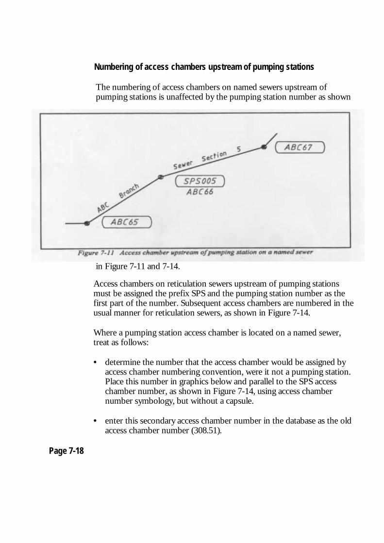
Numbering of access chambers upstream of pumping stations
The numbering of access chambers on named sewers upstream of pumping stations is unaffected by the pumping station number as shown
in Figure 7-11 and 7-14.
Access chambers on reticulation sewers upstream of pumping stations must be assigned the prefix SPS and the pumping station number as the first part of the number. Subsequent access chambers are numbered in the usual manner for reticulation sewers, as shown in Figure 7-14.
Where a pumping station access chamber is located on a named sewer, treat as follows:
• determine the number that the access chamber would be assigned by
access chamber numbering convention, were it not a pumping station. Place this number in graphics below and parallel to the SPS access chamber number, as shown in Figure 7-14, using access chamber number symbology, but without a capsule.
• enter this secondary access chamber number in the database as the old
access chamber number (308.51). Page 7-18
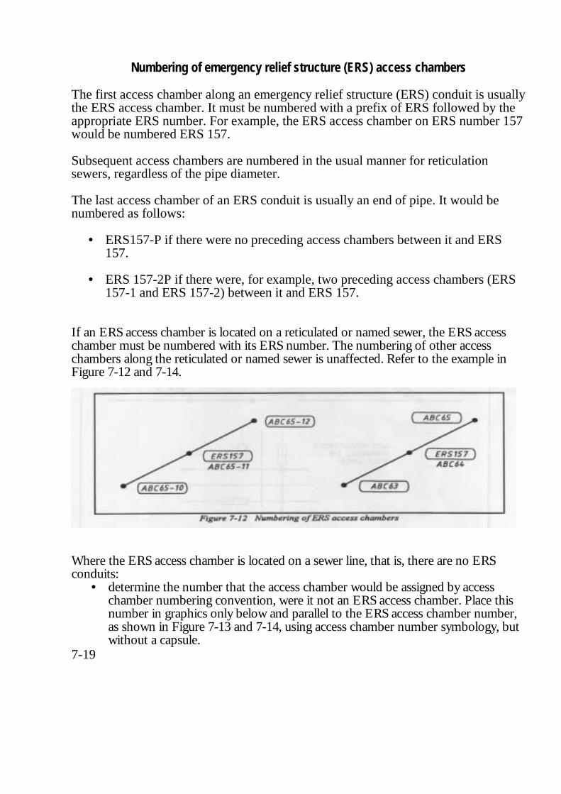
Numbering of emergency relief structure (ERS) access chambers
The first access chamber along an emergency relief structure (ERS) conduit is usually the ERS access chamber. It must be numbered with a prefix of ERS followed by the appropriate ERS number. For example, the ERS access chamber on ERS number 157 would be numbered ERS 157. Subsequent access chambers are numbered in the usual manner for reticulation sewers, regardless of the pipe diameter. The last access chamber of an ERS conduit is usually an end of pipe. It would be numbered as follows:
• ERS157-P if there were no preceding access chambers between it and ERS 157.
• ERS 157-2P if there were, for example, two preceding access chambers (ERS
157-1 and ERS 157-2) between it and ERS 157. If an ERS access chamber is located on a reticulated or named sewer, the ERS access chamber must be numbered with its ERS number. The numbering of other access chambers along the reticulated or named sewer is unaffected. Refer to the example in Figure 7-12 and 7-14.
Where the ERS access chamber is located on a sewer line, that is, there are no ERS conduits:
• determine the number that the access chamber would be assigned by access chamber numbering convention, were it not an ERS access chamber. Place this number in graphics only below and parallel to the ERS access chamber number, as shown in Figure 7-13 and 7-14, using access chamber number symbology, but without a capsule.
7-19

• enter this secondary access chamber number in the database as the associated
equipment number (318.28) and the old access chamber number (308.51). Access chamber capsules
Access chamber numbers must be placed inside an access chamber capsule. Access chamber capsules must be orientated radially about the centre of their respective access chamber and positioned at the preferred offset as detailed in Chapter 3, Table 3-21. Wherever possible, place the capsules along the same side of successive sewer pipe sections, at the same offset and angle. They should be placed inside the boundary of the property in which the access chamber is located. The capsule should not be placed parallel to the property boundary or road. Figure 7-13 shows the placement of access chamber capsules.
Page 7-20

Trunk sewer access shaft name
The trunk sewer access shaft name should be placed in graphics in upper case at an active angle of zero degrees (horizontal), opposite the centre of the shaft.
Note: The name should be shown on the plan. The name can be verified,
if necessary in Code List 305. If there is a discrepancy, place the name indicated in the code list.
Trunk sewer access shafts must be designated a unique access chamber number in the same manner as standard access chambers and a name.
Page 7-21
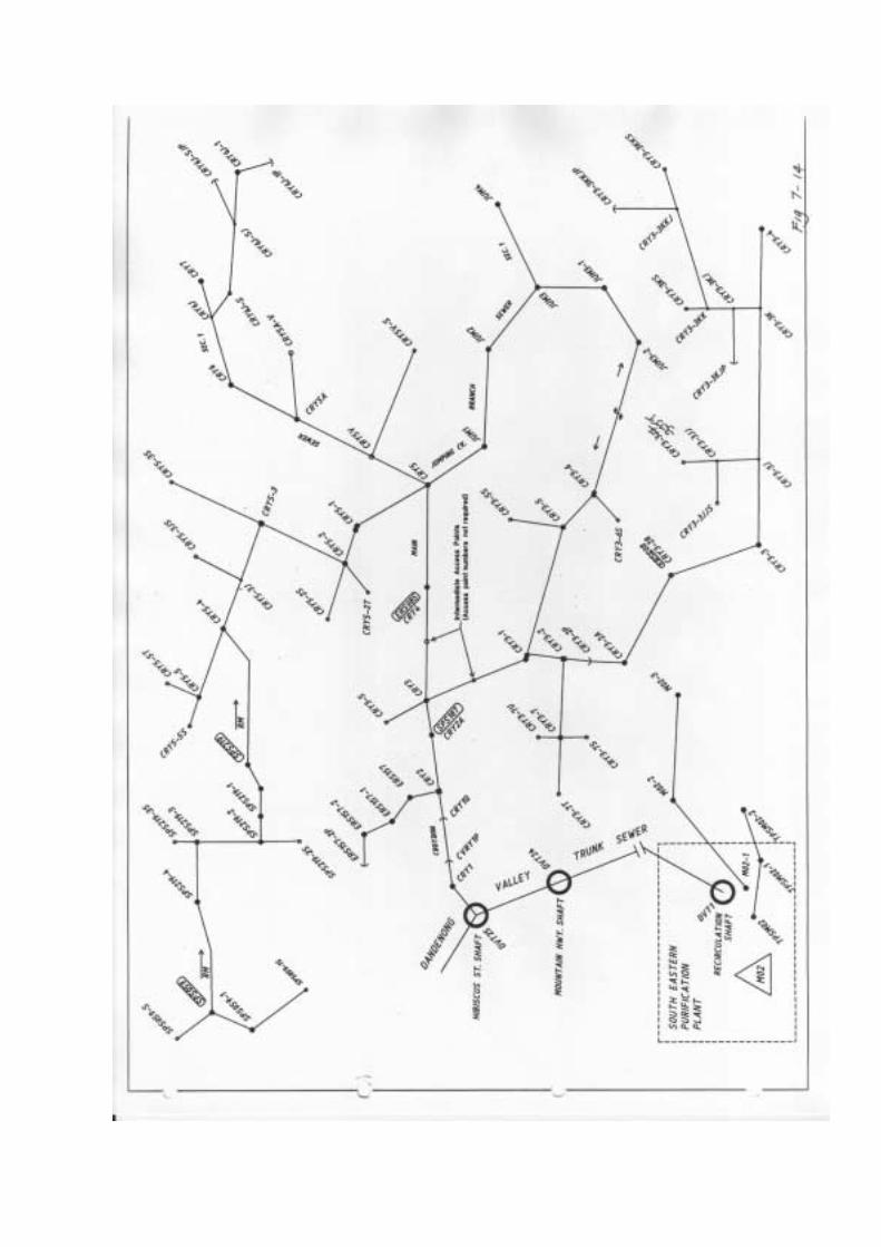
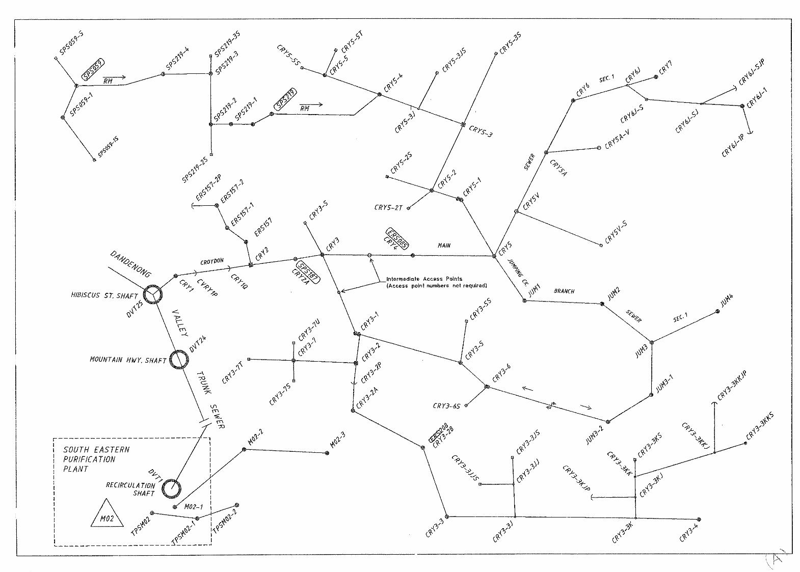
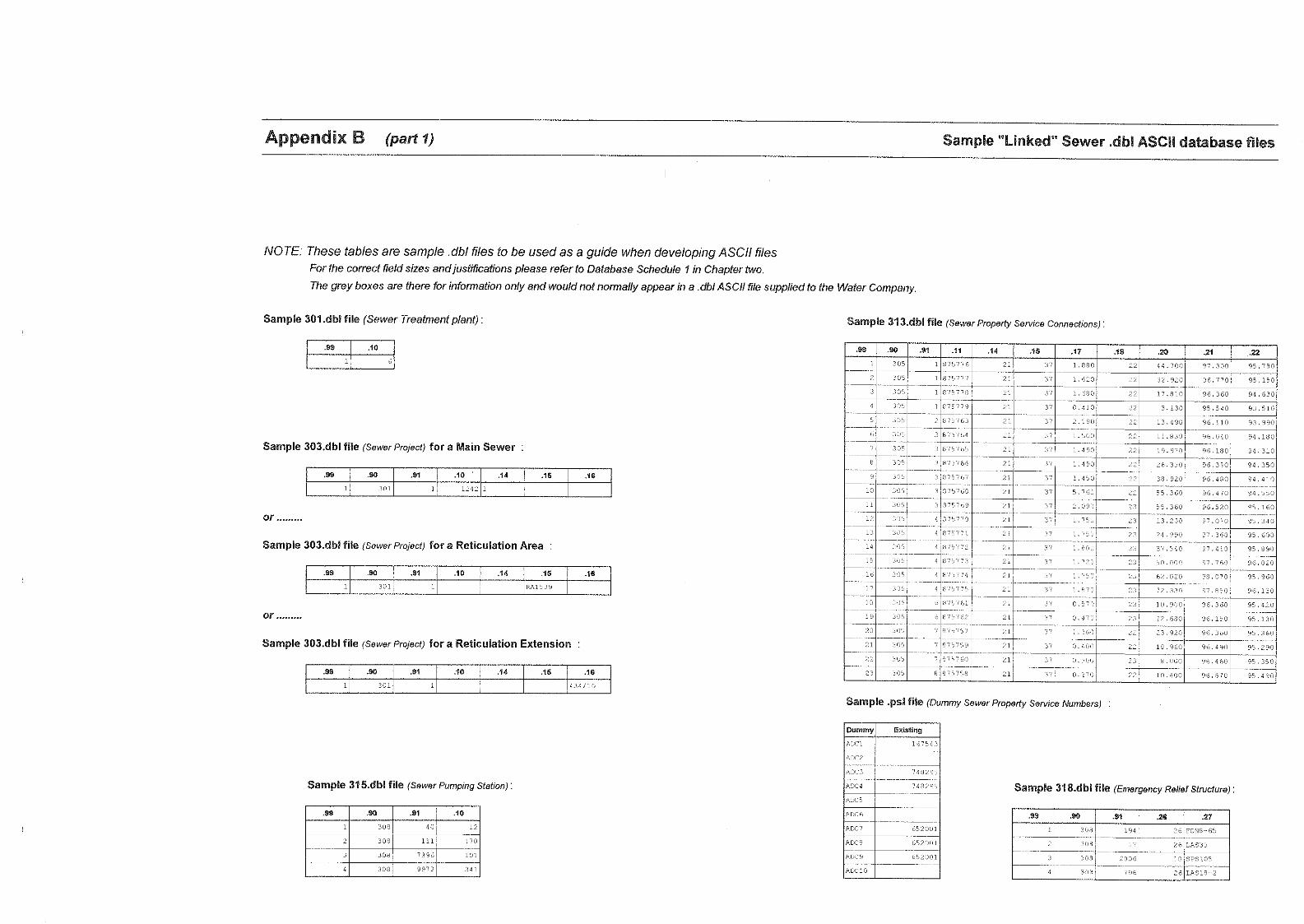
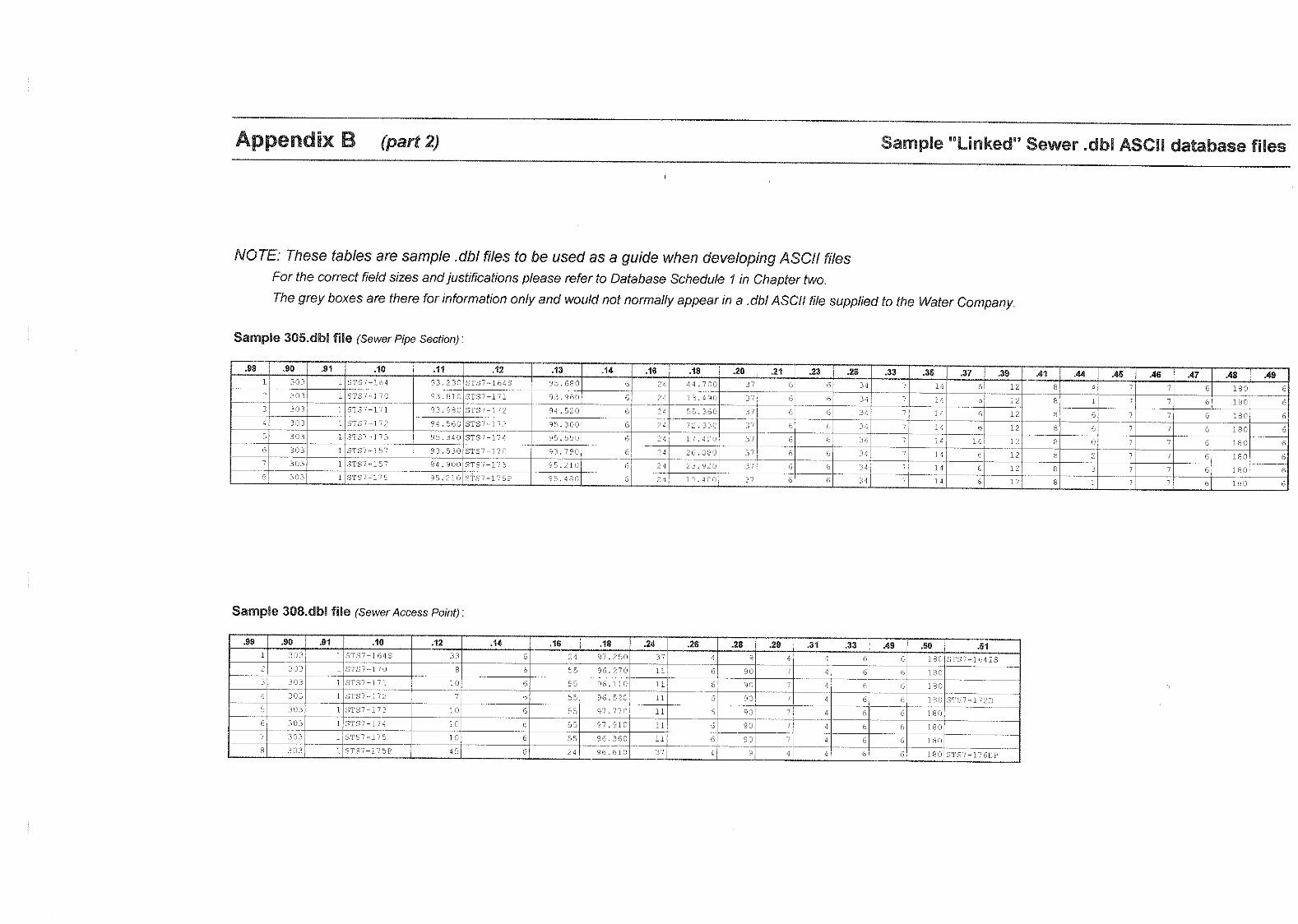
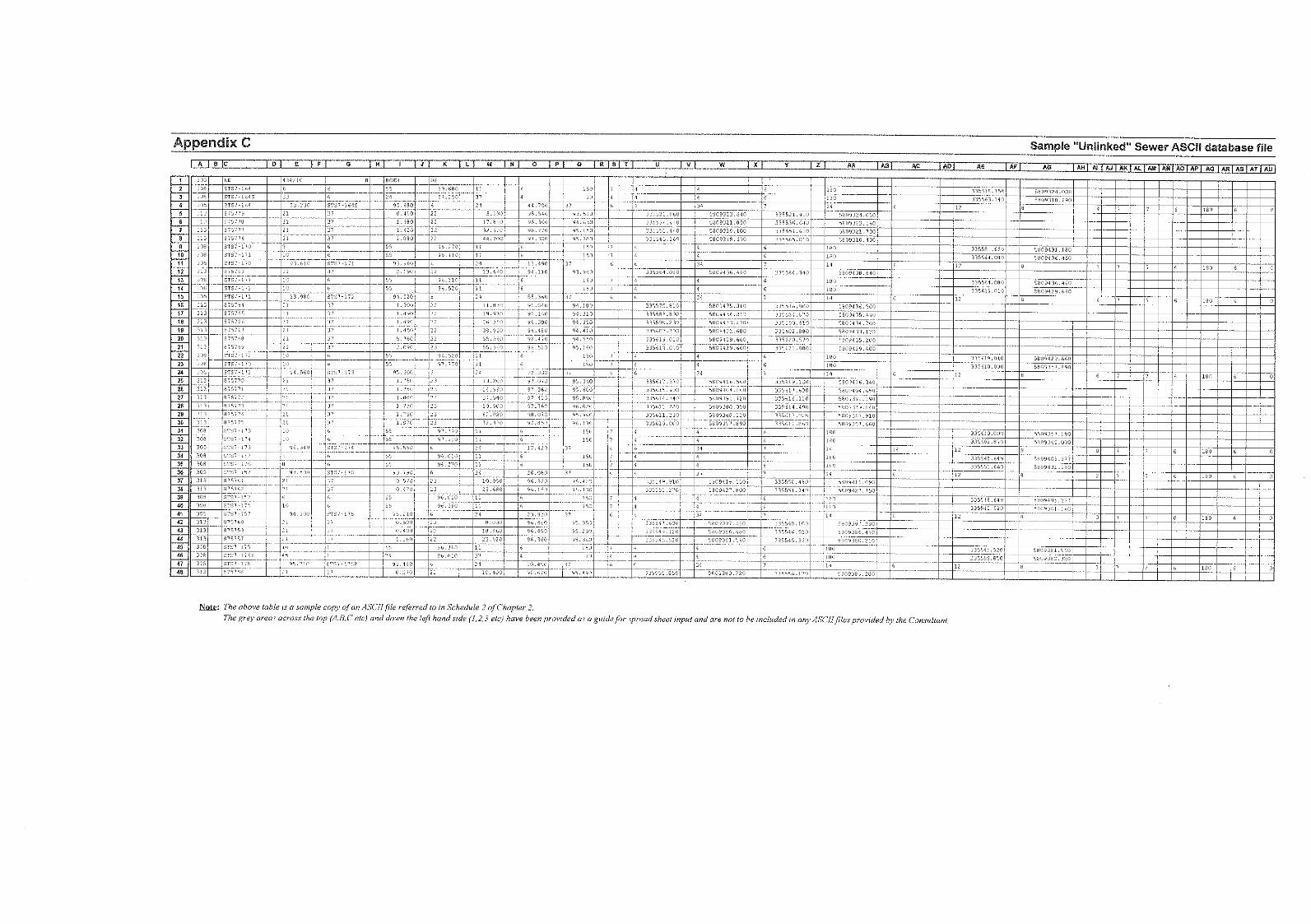
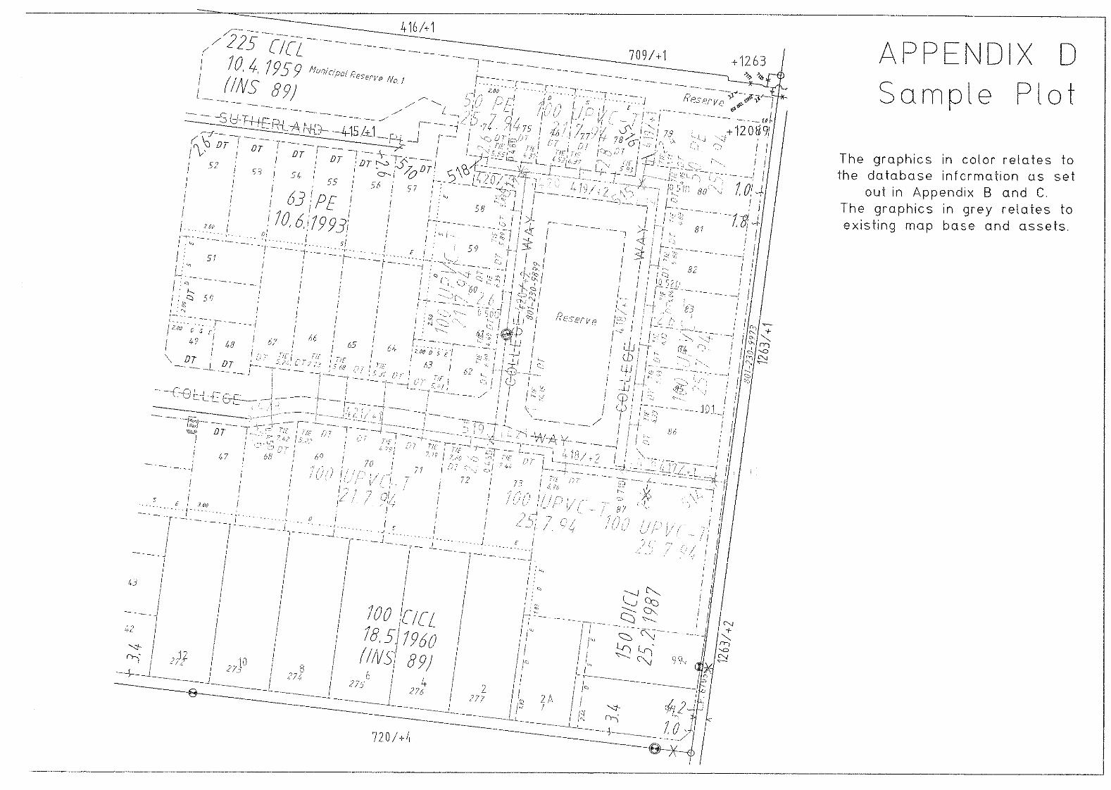
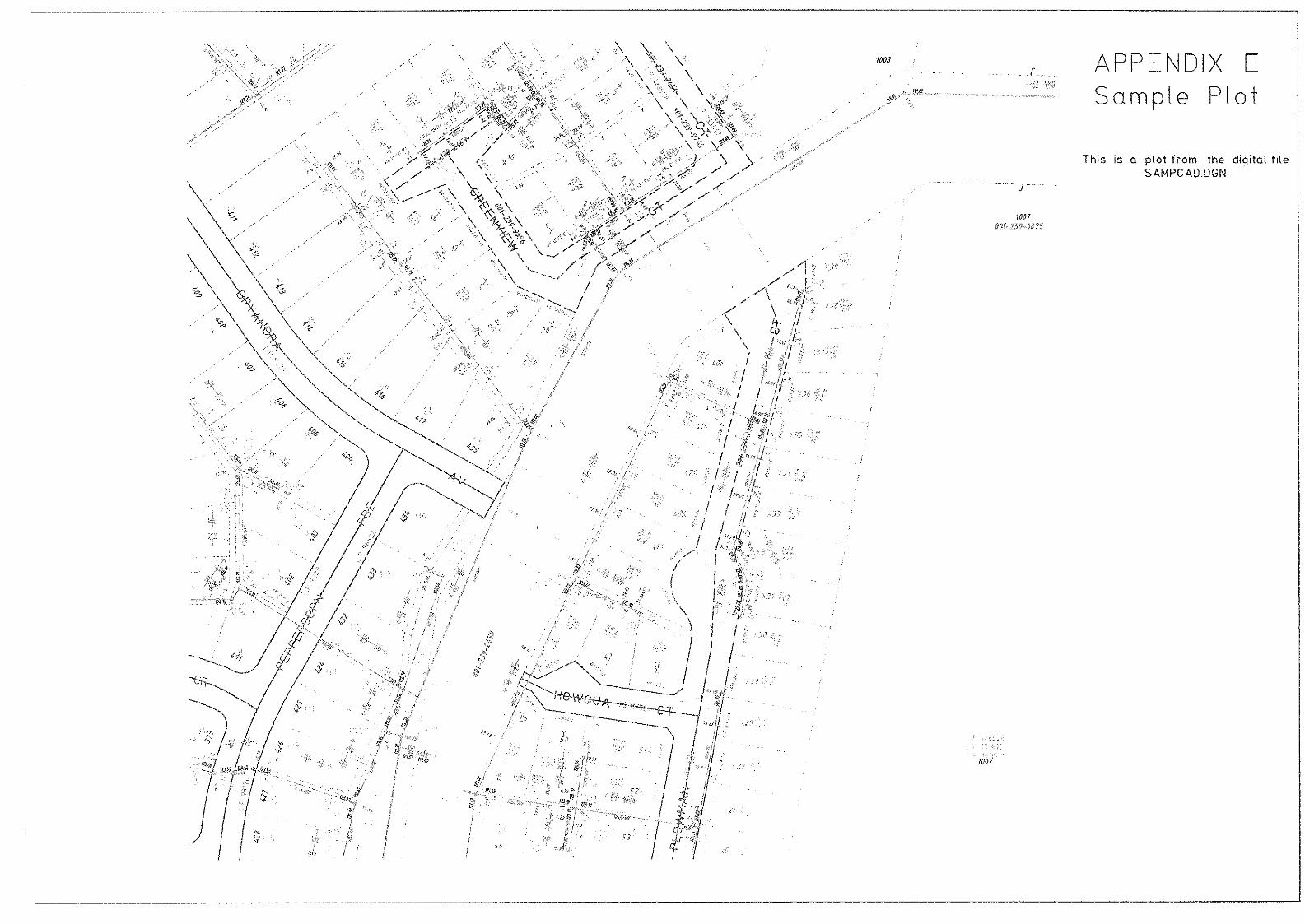

Subdivision Digital Input Manual
Second Edition No.
ii Supply of Digital Subdivisions Manual 24/1/95
Copyright Melbourne Water Ltd. @ 1995 Copyright Yarra Valley Water Ltd. @ 1995 Copyright South East Water Ltd. 0 1995 Copyright City West Water Ltd. 0 1995 All rights reserved. This publication is protected by copyright and is provided under licence. No part of this publication may be reproduced, distributed, transmitted, stored in a retrieval system, or reduced to any electronic medium without the written authority of the Managing Director of the Water Company. The Water Company assumes no responsibility for any errors in or omissions from this document or any damages arising out of the use or inability to use this document.
Changes may be made periodically to the information herein.
"Intergraph" and "IGDS" are registered trademarks of the Intergraph Corporation.
"MicroStation" is a trademark of Bentley Systems Incorporated and an affiliate of Intergraph Corporation. "VAX" is a trademark of Digital Equipment.
"UNIX" is a trademark of AT & T Bell Laboratories.
"PC-DOS" is a registered trademark of International Business Machines Corporation.
"AUTOCAD" is a trademark of Autodesk, Inc.
March 1995
Supply of Digital Subdivisions Manual 24/1/95 iii
Table of Contents Table of Contents iii About This Manual v Intended Audience
How to use this manual v Part 1 - Specifications v Chapter 1 Supply and Format of Data v Chapter 2 Graphical Specifications v Database Specifications Part 2 - Guidelines v Glossary of Terms vi Appendices vi Conventions used in this manual vi Related reference material vi Part 1 Specifications
Chapter 1 Supply and Format of Data
The Water Company's Responsibilities 1-1 Digital Data supplied by the Water Company 1.1 Documentation supplied by the Water Company 1-1
Consultant's responsibilities 1-1 Digital Data supplied by the consultant 1-2 1. MicroStation.DGN Format 1-2 2. AutoCad.DXF Format 1-3 Documentation supplied by the consultant 1-3 Licensed Surveyor's specification 1-3 Application details 1-4 File naming conventions 1-4 Data transfer 1-5 Formats and media 1-5 Batches 1-5
Chapter 2 Graphical Specifications 2-1 Content, structure and separation of the data 2-1 Information required in digital format 2-1 Information NOT required in digital format 2-2 Amended plans of subdivision 2-3 Graphics Schedule 1 - MicroStation.DGN 2-4 Graphics Schedule 2 -AutoCad.DXF Part 2 Guidelines
iv Supply of Digital Subdivisions Manual 24/1/95
Chapter 3 Placement of Data in Graphics Files 3-1 Proposed Road alignments 3-1 Proposed Road centrelines 3-3 Proposed Road Names and Road Types 3-4 Proposed Title Boundaries 3-5 Proposed Lot Numbers 3-6 Proposed Easement Lines 3-7 Proposed Easement Text 3-7 Proposed Reserves Text 3-9 Vinculums 3-10 Glossary 3-11 Consultant 3-11 DGN 3-11 DXF 3-11 FIS 3-11 Fiscolor.tbl 3-11 Fontlib 3-11 Global origin 3-11 POLARIS 3-11 Property boundary 3-12 Reserve 3-12 Road alignment 3-12 Road centreline 3-12 SAMPCAD 3-12 Seed file 3-12 Surveyors Code 3-12 Title boundary 3-12 Working Units 3-12 Appendix A Sample Plot A-1 Appendix B MicroStation DGN Level Specification B-1 Appendix C DXF Layer Specification C-1
Supply of Digital Subdivisions Manual 24/1/95 v
About This Manual
This manual details the graphics data specifications required by the Water Company for the supply of digital subdivision data.
Intended Audience
This manual defines the requirements and specifications for the supply of digital subdivision data to the Water Company by any person or company, hereafter known as the Consultant.
How to use this manual
This manual is divided into two parts. Part 1 - Specifications
Part 1 consists of two chapters, which describe the requirements of graphics data.
Chapter 1 Supply and Format of Data
This part describes the responsibilities of the Water Company and consultants with regard to the supply of digital data and documentation. It includes details about the supply and format of all digital data and file naming conventions.
Chapter 2 Graphical Specifications
This chapter describes the graphics data requirements. It includes the level structure, symbology specifications and associated graphics specifications.
Database Specifications
It is to be noted that there are no database requirements for the supply of digital subdivision information.
Part 2 - Guidelines
Part 2 consists of one chapter which details the presentation standards associated with the graphics input of digital subdivisions.
vi Supply of Digital Subdivisions Manual 24/1/95
Glossary of Terms
♦ This chapter contains a glossary of terms used in this manual.
Appendices The Appendices contain:
♦ A plot of part of the Water Company's map base. (derived from SAMPCAD.DGN),
♦ DGN Layer Specification List,
♦ DXF Layer Specification -ist.
Conventions used in this manual
Italics are used when reference is made to information in other chapters of this manual. For example, refer to the Graphics Schedule 1 in Chapter. 2. Italics are also used to emphasise words or phrases.
♦ Diamond bullets are used for lists of items or topics.
Related reference material
Survey Manual.

Part 1 Specifications

Supply of Digital Subdivisions Manual 24/1/95 1- 1
Chapter 1 Supply and Format of Data
This chapter describes the formats in which digital subdivision information must be supplied to the Water Company. It describes the responsibilities of the Water Company and consultants engaged in the process of supplying this information.
The Water Company's Responsibilities Digital Data supplied by the Water Company
On request the Water Company will provide the appropriate digital data files: ♦ font library - file name fontlib (MicroStation format),
♦ colour table - file name fiscolor.tbl (MicroStation users), ♦ seed graphics file - file name basemap.DGN (NficroStation users),
- file name basemap.D@ (.DXF format users).
Documentation supplied by the Water Company
For the purpose of digital subdivision information there is no documentation required to be supplied by the Water Company.
Consultant's responsibilities
It is the responsibility of the consultant to supply the Water Company with digital data in the required format. This can be either in MicroStation DGN or AutoCad DXF formats.
The Water Company uses DGN format graphics files.
The order of preference the Water Company would like digital information supplied is:
1. MicroStation DGN format graphics information as per Graphics
Schedule 1 in Chapter 2.
2. AutoCad DXF format graphics information as per Graphics Schedule 2 in Chapter 2.
AutoCad DXF format graphics files have to be converted to MicroStation.DGN format by the Water Company to enable them to be merged into the FIS.

24/1/95 Supply of Digital Subdivisions Manual 1-2
It is the responsibility of the consultant to supply the Water Company with data using either of the required formats.
Submissions that are not in accordance with all relevant Water Company specifications and relevant Australian Standards will be returned to the Consultant for review. The consultant must ensure that non conforming submissions (digital and non digital) are resolved and the works resubmitted to the Water Company within 10 (ten) working days.
Digital Data supplied by the consultant
1. MicroStation.DGN Format
MicroStation graphics data must be supplied to the Water Company in one of the following formats: 1. MicroStation 32/MicroStation PC Design Software two dimensional design files (2D), version 3.x 2. Intergraph Interactive Graphic Design Software (IGDS) two
dimensional design files (2D), version 8.8 or later.
The Water Company will supply, upon request. a seed graphics file (basemap.DGN) which must be used as the basis to create subsequent graphics files.
Graphics files must be supplied to the Water Company:
♦ in accordance with the MicroStation.DGN Graphical Schedule 1 in Chapter 2,
♦ with the digital subdivision orientated to the Australian Map Grid (AMG) Zone 55
as defined by the field survey (refer to the Survey Manual),
♦ contain the data in two dimensional (2D) format,
♦ with file names in accordance with File naming conventions as described later in
this Chapter,
♦ with all deleted elements eliminated. A graphic compress must be performed,
♦ with no shared cells,
♦ with all locks set to “off”, for example, the graphic group, snap, and grid lock
♦ with graphic group = 0 (dropped),
♦ with view attributes set to "off' for enter data fields.
♦ with no named views in file,
♦ containing no cells other than the ones supplied in the cell library except graphical
error flags,
♦ with all type 66 elements deleted,
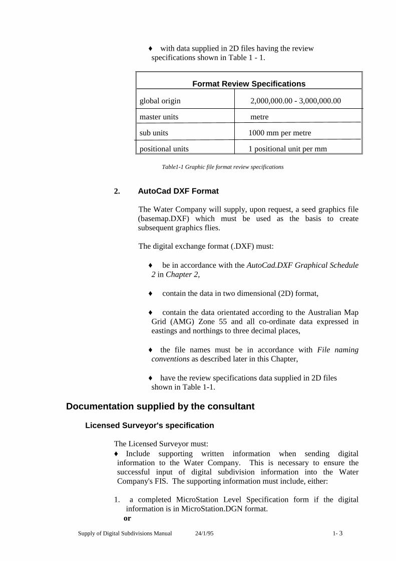
Supply of Digital Subdivisions Manual 24/1/95 1- 3
♦ with data supplied in 2D files having the review specifications shown in Table 1 - 1.
Format Review Specifications
global origin 2,000,000.00 - 3,000,000.00
master units metre
sub units 1000 mm per metre
positional units 1 positional unit per mm
Table1-1 Graphic file format review specifications
2. AutoCad DXF Format
The Water Company will supply, upon request, a seed graphics file (basemap.DXF) which must be used as the basis to create subsequent graphics flies. The digital exchange format (.DXF) must:
♦ be in accordance with the AutoCad.DXF Graphical Schedule 2 in Chapter 2,
♦ contain the data in two dimensional (2D) format,
♦ contain the data orientated according to the Australian Map Grid (AMG) Zone 55 and all co-ordinate data expressed in eastings and northings to three decimal places,
♦ the file names must be in accordance with File naming conventions as described later in this Chapter,
♦ have the review specifications data supplied in 2D files shown in Table 1-1.
Documentation supplied by the consultant
Licensed Surveyor's specification
The Licensed Surveyor must: ♦ Include supporting written information when sending digital information to the Water Company. This is necessary to ensure the successful input of digital subdivision information into the Water Company's FIS. The supporting information must include, either:
1. a completed MicroStation Level Specification form if the digital
information is in MicroStation.DGN format. or
24/1/95 Supply of Digital Subdivisions Manual 1-4
2. a completed AutoCad Layer Specification form if the digital information is in AutoCad DXF format.
Note: The layer specification forms are available in the Certification Lists
chapter of the Survey Manual and in Appendices B and C respectively of this manual.
♦ for the first (initial) supply of digital subdivision information to the
Water Company, the consultant will make an application to the Water Company to obtain a surveyor's code (a unique code number identifying the Licensed Surveyor). This must be done before submitting the digital information. Once obtained this code is to be used for all future submissions.
Application details
As part of the application for conditions the Owner must provide the following details to the Water Company:
♦ Licensed Surveyor's name,
♦ Licensed Surveyor's code,
♦ the format of the digital information (.DGN or.DXF),
♦ appropriate disk,
♦ the Titles Office reference number eg. PS 324556,
♦ a paper copy (hard copy) of the proposed subdivision (Titles Office plan),
♦ Acceptance of Subdivision Digital Information on Disk Certification List.
File naming conventions
When naming the files on disk, use the titles Office Plan of Subdivision (PS) number with an extension of either .DGN or 324556 .DXF (leaving off the letters PS)
Supply of Digital Subdivisions Manual 24/1/95 1- 5
Data transfer Formats and media
Data must be delivered, in a virus free, non-compressed or non-zipped PC DOS format, to the Water Company in either MicroStation or AutoCad format. (MicroStation being the preferred format)
The information must not be supplied in a compressed or zipped format.
Other formats will not be accepted unless previously arranged with the Water Company.
Note: If requested by the consultant the disks will be returned upon
completion of a successful transfer to the Water Company's Facilities Information System.
Batches
All data relating to one job must appear where practicable on a single diskette. However, when a job crosses municipal boundaries, the data for each municipality must be supplied on a separate media.
Only one job is to be supplied on one media (eg diskette). Additional jobs are to be supplied on separate media.
Documentation which indicates the following must accompany each batch of data:
♦ a listing of files contained on the media,
♦ the manner in which data was written to the media, (eg DOS)

24/1/95 Supply of Digital Subdivisions Manual 1-6

Supply of Digital Subdivisions Manual 24/1/95 2-1
Chapter 2 Graphical Specifications This chapter contains the symbology specifications for the graphical representation of subdivisional elements. Symbology is specified in terms of level, color, line weight, line style, font, height, width and justification of text, and whether or not there is a cell to represent the item.
Content, structure and separation of the data
The digital plan of subdivision must be supplied using the following criteria:
♦ the digital information must represent the computed plan that is lodged with the responsible authority for certification,
♦ the proposed development must be connected to at least two co- ordinated pennanent marks of known Australian Map Grid (AMG) position and shown on the face sheet of the Plan of Subdivision,
♦ the geographical position of the digital subdivision information must reflect the AMG position of the subdivision. (ie. the digital subdivision must be orientated to its correct AMG position).
Information required in digital format
The digital information must be on different MicroStation .DGN levels or AutoCad .DXF layers to reflect the separation of digital data into the following categories:
♦ road aligrurents,
♦ centrelines of roads,
♦ road nalreS,
♦ property/title boundaries,
♦ easements and their related text,
♦ lot numbers,
♦ reserves text.
Tables 2-1 and 2-2 contain detailed requirements for DGN level symbologies and DXF layer names respectively.

24/1/95 Supply of Digital Subdivisions Manual 2-2
Information NOT required in digital format
The Water Company does not require the following information included in the supply of digital subdivision information:
♦ contours,
♦ spot heights,
♦ subdivisional boundary,
♦ subdivision face sheet,
♦ North points,
♦ Surveyor's Logo etc,
♦ al1otment areas,
♦ dimensions,
♦ abuttals,
♦ tangent points and splay corner intersection points,
♦ plan borders.
All of the non required information would be deleted by the Water Company when the digital subdivision is input into the digital map base.
Supply of Digital Subdivisions Manual 24/1/95 2-3
Amended plans of subdivision
For a subdivision which has been previously submitted, has had amendments made and is being resubmitted, the following criteria is to be followed:
♦ Re-submission in digital format together with a hard copy plan:
- where allotments have been added or removed from the previous
submission,
- where the dimensions of properties have varied.
♦ Re-submission on a hard copy plan only:
- where the subdivision has a change of road names,
- alteration to any textual information in general,
- addition or removal of easements.
If there is any doubt regarding whether to resubmit the subdivision in digital or hard copy format contact the Water Company for advice.
Documentation is to accompany these amendments to bring the nature of the amendments to the attention of the Water Company.
24/1/95 Supply of Digital Subdivisions Manual 2-4
Graphics Schedule 1 - MicroStation .DGN
Table 2-1 sets out the symbologies required by the Water Company for proposed subdivisions.
The headings for each column represent the following:
Level = the level on which the graphical elements are placed
Color = the color to be used (using the color table fiscolor.tbl)
Weight = the weight (line thickness)to be used
Style = the line style number to be used
Font = the font number to be used (using the fontlib)
Height = the height of the text (in metres)
Width = the width of the text (in metres)
Just'n = the justification to be used for text placement
Where: Cl' = Centre Top CB = Centre Bottom CL = Centre Left CR = Centre Right
CC = Centre Centre
Cell = the cell name to be used (using the cell library fiscell.cel)
By using the fiscolor.tbl and fontlib files available from the Water Company it will ensure that the correct colors and font styles are supplied by the consultant.
Refer to Part 2 - Guidelines for information relating to the placement and positioning of graphical elements as required by the Water Company.
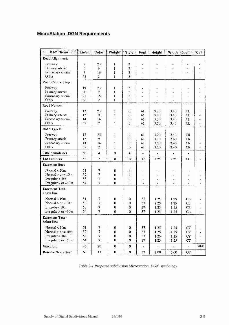
Supply of Digital Subdivisions Manual 24/1/95 2-5
MicroStation .DGN Requirements
Table 2-1 Proposed subdivision Microstation .DGN symbology
24/1/95 Supply of Digital Subdivisions Manual 2-6
Graphics Schedule 2 -AutoCad .DXF
Table 2-2 sets out the symbologies required by the Water Company for proposed subdivisions.
The headings for each column represent the following:
DXF Layer Number = the layer on which the graphical elements are placed
DXF Layer Narre = the layer on which the graphical elements are placed
DXF Color = the color to be used (using the color table
fiscolor.tbl)
DXF Font style = the name of a created font style that should appear similar
to the MicroStation font (refer to Water & Sewer manuals)
DXF Text Height = the height of the text (in mm)
DXF Text Width = the width of the text (in mrn)
Just'n = the justification to be used for text placement.
Where: CT = Centre Top CB = Centre Bottom CL = Centre Left CR = Centre Right CC = Centre Centre
DXF Block = Blocks to be developed by consultant where required
Note: The specifications set out in Table 2-2 are provided as a guide only. The DXF layer name and number are the ones suggested to be used on the layer specification form. The rest of the columns are provided to represent the closest symbology match to the Water Company's FIS symbologies. The Water Company's translator will convert the DXF data to the correct DGN levels and symbology using the layer specification table.
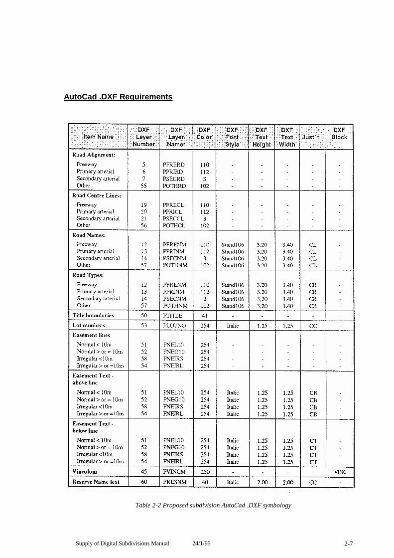
Supply of Digital Subdivisions Manual 24/1/95 2-7
AutoCad .DXF Requirements
Table 2-2 Proposed subdivision AutoCad .DXF symbology

24/1/95 Supply of Digital Subdivisions Manual 2-8

Supply of Digital Subdivisions Manual 24/1/95 2-9


Part 2 Guidelines

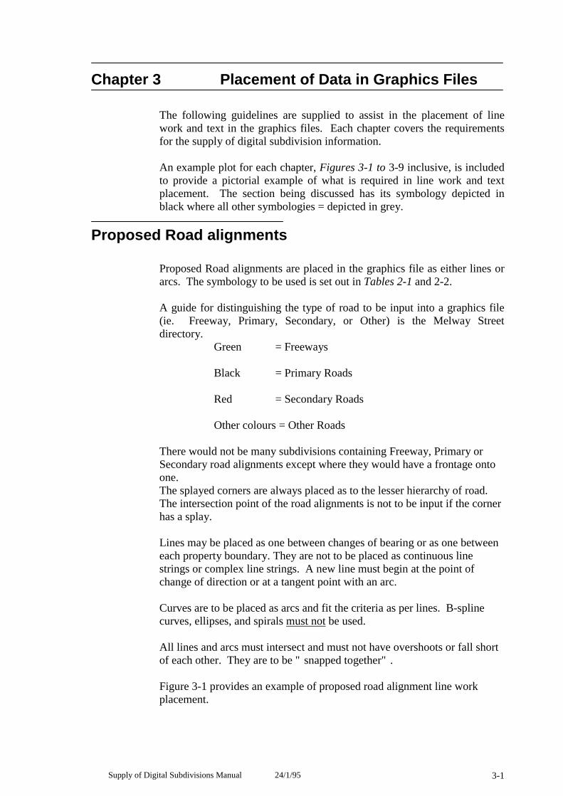
Supply of Digital Subdivisions Manual 24/1/95 3-1
Chapter 3 Placement of Data in Graphics Files
The following guidelines are supplied to assist in the placement of line work and text in the graphics files. Each chapter covers the requirements for the supply of digital subdivision information.
An example plot for each chapter, Figures 3-1 to 3-9 inclusive, is included to provide a pictorial example of what is required in line work and text placement. The section being discussed has its symbology depicted in black where all other symbologies = depicted in grey.
Proposed Road alignments
Proposed Road alignments are placed in the graphics file as either lines or arcs. The symbology to be used is set out in Tables 2-1 and 2-2.
A guide for distinguishing the type of road to be input into a graphics file (ie. Freeway, Primary, Secondary, or Other) is the Melway Street directory.
Green = Freeways
Black = Primary Roads
Red = Secondary Roads
Other colours = Other Roads
There would not be many subdivisions containing Freeway, Primary or Secondary road alignments except where they would have a frontage onto one. The splayed corners are always placed as to the lesser hierarchy of road. The intersection point of the road alignments is not to be input if the corner has a splay.
Lines may be placed as one between changes of bearing or as one between each property boundary. They are not to be placed as continuous line strings or complex line strings. A new line must begin at the point of change of direction or at a tangent point with an arc.
Curves are to be placed as arcs and fit the criteria as per lines. B-spline curves, ellipses, and spirals must not be used.
All lines and arcs must intersect and must not have overshoots or fall short of each other. They are to be "snapped together". Figure 3-1 provides an example of proposed road alignment line work placement.

24/1/95 Supply of Digital Subdivisions Manual 3-2
Figure3-1 Example of Proposed Road alignment placement
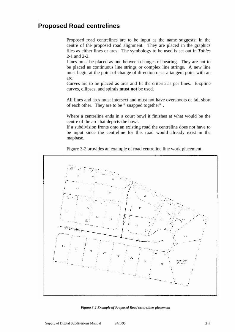
Supply of Digital Subdivisions Manual 24/1/95 3-3
Proposed Road centrelines
Proposed road centrelines are to be input as the name suggests; in the centre of the proposed road alignment. They are placed in the graphics files as either lines or arcs. The symbology to be used is set out in Tables 2-1 and 2-2. Lines must be placed as one between changes of bearing. They are not to be placed as continuous line strings or complex line strings. A new line must begin at the point of change of direction or at a tangent point with an arc. Curves are to be placed as arcs and fit the criteria as per lines. B-spline curves, ellipses, and spirals must not be used.
All lines and arcs must intersect and must not have overshoots or fall short of each other. They are to be "snapped together".
Where a centreline ends in a court bowl it finishes at what would be the centre of the arc that depicts the bowl. If a subdivision fronts onto an existing road the centreline does not have to be input since the centreline for this road would already exist in the mapbase.
Figure 3-2 provides an example of road centreline line work placement.
Figure 3-2 Example of Proposed Road centrelines placement
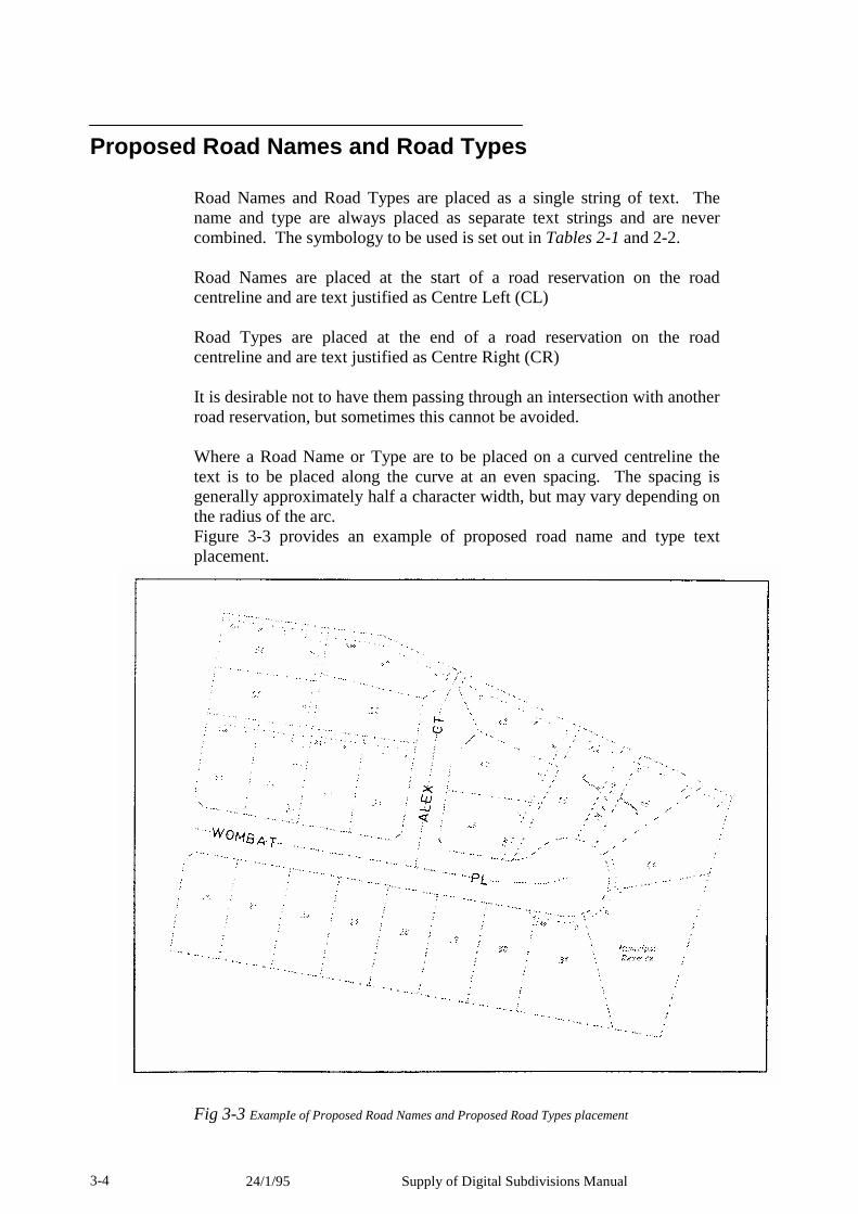
24/1/95 Supply of Digital Subdivisions Manual 3-4
Proposed Road Names and Road Types
Road Names and Road Types are placed as a single string of text. The name and type are always placed as separate text strings and are never combined. The symbology to be used is set out in Tables 2-1 and 2-2.
Road Names are placed at the start of a road reservation on the road centreline and are text justified as Centre Left (CL)
Road Types are placed at the end of a road reservation on the road centreline and are text justified as Centre Right (CR)
It is desirable not to have them passing through an intersection with another road reservation, but sometimes this cannot be avoided.
Where a Road Name or Type are to be placed on a curved centreline the text is to be placed along the curve at an even spacing. The spacing is generally approximately half a character width, but may vary depending on the radius of the arc. Figure 3-3 provides an example of proposed road name and type text placement.
Fig 3-3 ExampIe of Proposed Road Names and Proposed Road Types placement
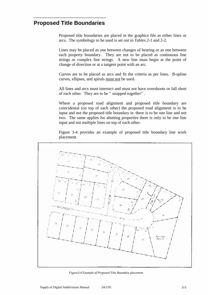
Supply of Digital Subdivisions Manual 24/1/95 3-5
Proposed Title Boundaries
Proposed title boundaries are placed in the graphics file as either lines or arcs. The symbology to be used is set out in Tables 2-1 and 2-2.
Lines may be placed as one between changes of bearing or as one between each property boundary. They are not to be placed as continuous line strings or complex line strings. A new line must begin at the point of change of direction or at a tangent point with an arc.
Curves are to be placed as arcs and fit the criteria as per lines. B-spline curves, ellipses, and spirals must not be used.
All lines and arcs must intersect and must not have overshoots or fall short of each other. They are to be "snapped together".
Where a proposed road alignment and proposed title boundary are coincidental (on top of each other) the proposed road alignment is to be input and not the proposed title boundary ie. there is to be one line and not two. The same applies for abutting properties there is only to be one line input and not multiple lines on top of each other.
Figure 3-4 provides an example of proposed title boundary line work placement.
Figure3-4 Example of Proposed Title Boundary placement
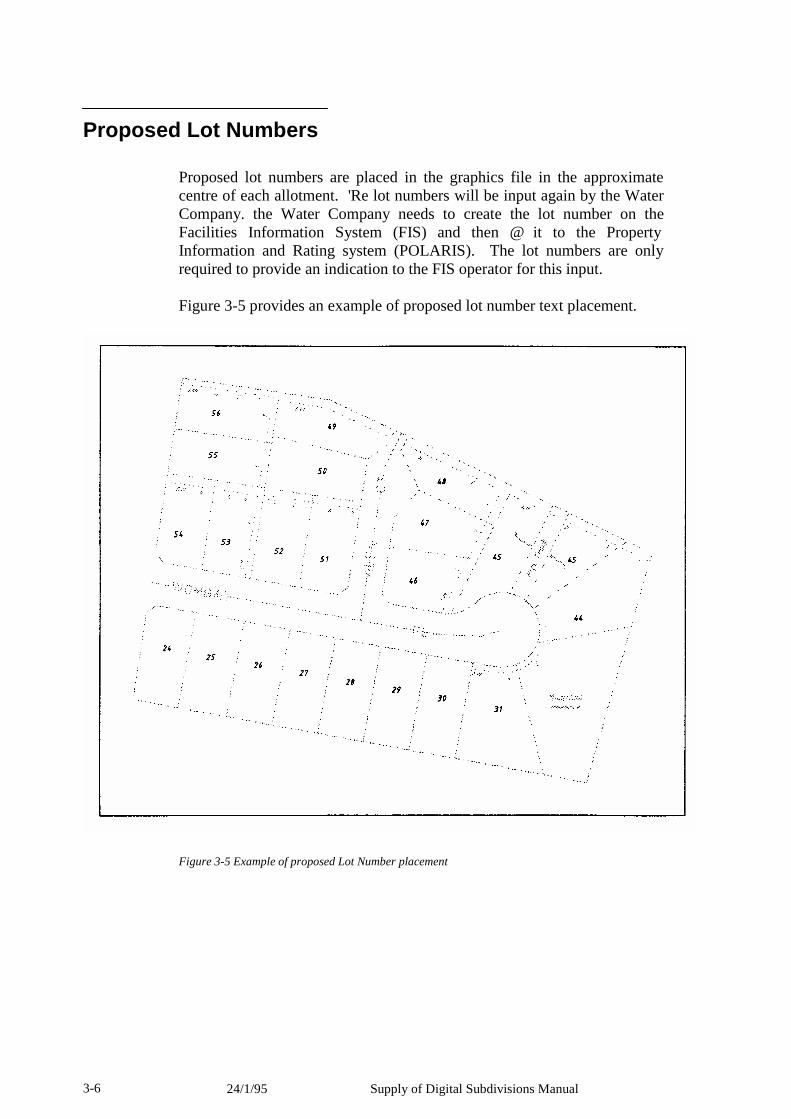
24/1/95 Supply of Digital Subdivisions Manual 3-6
Proposed Lot Numbers
Proposed lot numbers are placed in the graphics file in the approximate centre of each allotment. 'Re lot numbers will be input again by the Water Company. the Water Company needs to create the lot number on the Facilities Information System (FIS) and then @ it to the Property Information and Rating system (POLARIS). The lot numbers are only required to provide an indication to the FIS operator for this input.
Figure 3-5 provides an example of proposed lot number text placement.
Figure 3-5 Example of proposed Lot Number placement

Supply of Digital Subdivisions Manual 24/1/95 3-7
Proposed Easement Lines
Proposed easement lines are placed in the graphics file as either lines or arcs. 'Re symbology is to be used as set out in Tables 2-1 and 2-2.
Lines must be placed as one between changes of bearing or as one between each property boundary. They are not to be placed as continuous line strings or complex line strings. A new line must begin at the point of change of direction or at a tangent point with an arc.
Curves are to be placed as arcs and fit the criteria as per lines. B-spline curves, ellipses, and spirals must not be used.
All lines and arcs must intersect and must not have overshoots or fall short of each other. They are to be "snapped together".
Proposed easement lines are placed at the correct offset distance, ground scale, away from title boundaries. Easement lines must not be placed under road alignment or title boundary line work.
Where an easement exists in a newly created Road, from an earlier stage of the development, the information relating to such easement is not required. Figure 3-6 provides an example of proposed easement fine work placement.
Proposed Easement Text
Proposed easement text is placed in the graphics file evenly spaced along the easement line at an offset of 1.15 metres (ground scale) to the text justification point. If the text is placed above the line it has a justification of Centre Bottom (CB) and if placed below the line it has a justification of Centre Top (CT) The symbology is to be used as set out in Tables 2-1 and 2-2.
The easement text traditionally placed on plans of subdivision (ie E-1 E-2 etc) are not required to be placed in graphics. In viewing the graphics file when merged into the map base this text is of no relevance and the convention used throughout the development of the map base is therefore to be used.
For example:
If a 2.50 metre Drainage and Sewerage Easement is placed in graphics the text 2.50 D S E is to be placed. These would be placed as four individual text elements and not as a continuous text string.
Figure 3-6 provides an example of proposed easement text placement.
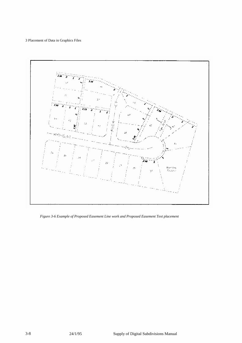
24/1/95 Supply of Digital Subdivisions Manual 3-8
3 Placement of Data in Graphics Files
Figure 3-6 Example of Proposed Easement Line work and Proposed Easement Text placement
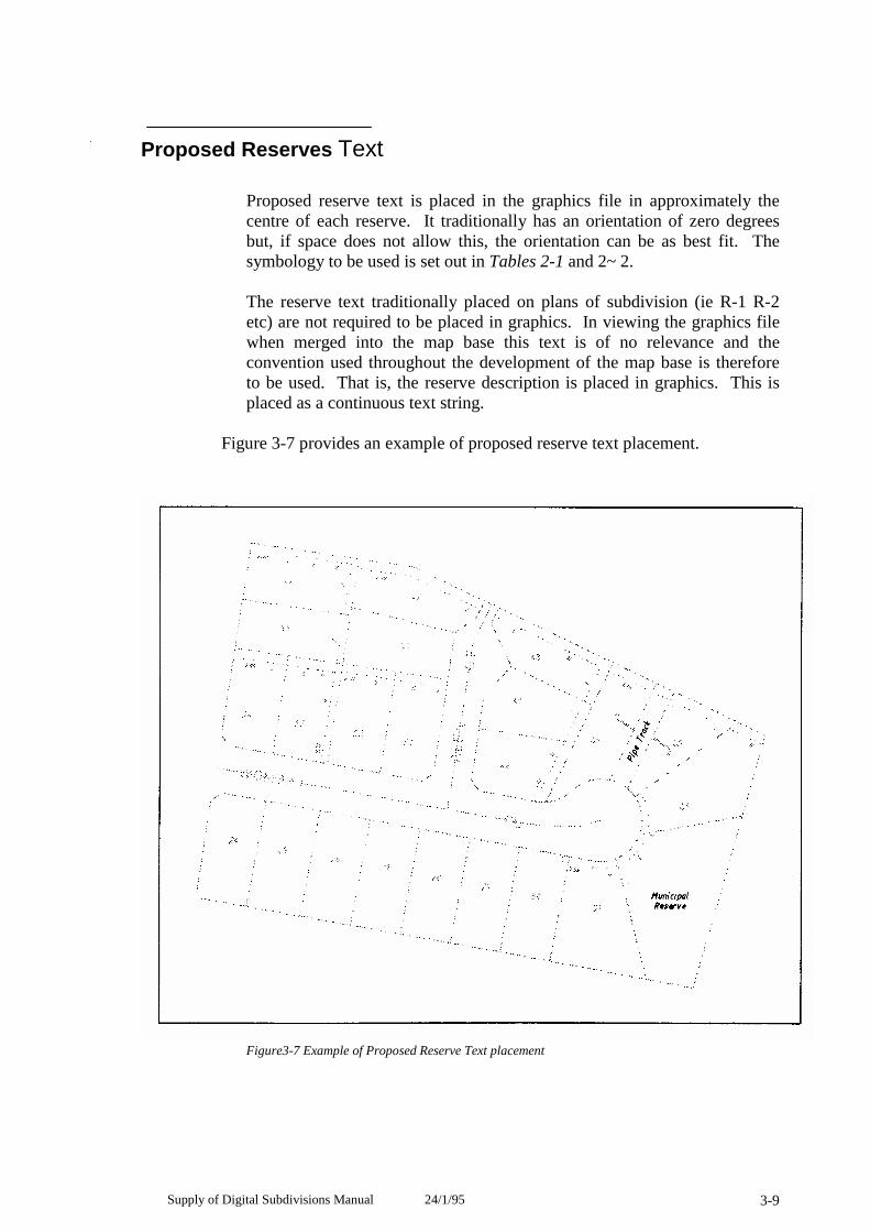
Supply of Digital Subdivisions Manual 24/1/95 3-9
Proposed Reserves Text
Proposed reserve text is placed in the graphics file in approximately the centre of each reserve. It traditionally has an orientation of zero degrees but, if space does not allow this, the orientation can be as best fit. The symbology to be used is set out in Tables 2-1 and 2~2.
The reserve text traditionally placed on plans of subdivision (ie R-1 R-2 etc) are not required to be placed in graphics. In viewing the graphics file when merged into the map base this text is of no relevance and the convention used throughout the development of the map base is therefore to be used. That is, the reserve description is placed in graphics. This is placed as a continuous text string.
Figure 3-7 provides an example of proposed reserve text placement.
Figure3-7 Example of Proposed Reserve Text placement
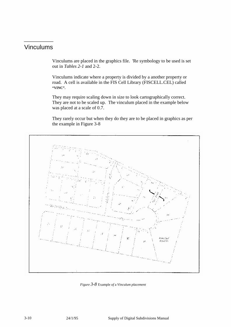
24/1/95 Supply of Digital Subdivisions Manual 3-10
Vinculums
Vinculums are placed in the graphics file. 'Re symbology to be used is set out in Tables 2-1 and 2-2.
Vinculums indicate where a property is divided by a another property or road. A cell is available in the FIS Cell Library (FISCELL.CEL) called “VINC”.
They may require scaling down in size to look cartographically correct. They are not to be scaled up. The vinculum placed in the example below was placed at a scale of 0.7.
They rarely occur but when they do they are to be placed in graphics as per the example in Figure 3-8
Figure 3-8 Example of a Vinculum placement
Supply of Digital Subdivisions Manual 24/1/95 3-11
Glossary Consultant
Any person or company involved in the provision and supply of digital subdivisional information
DGN
The abbreviation and file name extension given to MicroStation graphics files.
DXF
The abbreviation and file name extension given to graphics files that can be created in various graphics packages. It was created by Autodesk, Inc. for exchanging graphics files - the word DXF stands for Drawing Interchange Format.
FIS
The Water Company's Facilities Information System. The computer system used by the Water Company to store and retrieve their digital information relating to subdivisions, water supply, sewer and drainage.
Fiscolor.tbi
The Water Company's color table file used in MicroStation DGN files. By using this file the correct colors used by the Water Company will be obtained.
Fontlib
Ale Water Company's font file used in MicroStation DGN files. By using this file the correct font styles used by the Water Company will be obtained.
Global origin
The Easting and Northing origin of a file. This being the bottom left hand corner of the file. Refer to Table 1-1.
POLARIS
71e Water Company's Property On Line And Retrieval Information System used to store the Water Company's rating and metering information.
24/1/95 Supply of Digital Subdivisions Manual 3-12
Property boundary
Refer Title boundary
Reserve A property set aside for a specific purpose (eg municipal uses, pipe tracks, tree reserves, drainage etc)
Road alignment
A line depicting the road, reservation boundary
Road centrefine
A line depicting the centre of a road reservation.
SAMPCAD A digital file available from the Water Company (in DGN or DXF format) providing an example of what the Water Company's map base looks like.
Seed file
An empty digital file with the correct global origin and working units, thus enabling the user to create files with the correct attributes.
Surveyors Code
A unique code number identifying the Licensed Surveyor to enable the transfer of digital subdivision information to the digital map base. This code is available upon request from the Water Company
Title boundary
The line depicting the boundary between properties on a plan of subdivision.
Working Units
The units of measure that the graphics file uses. Refer to Table 1-1.
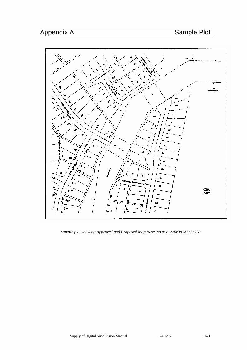
Supply of Digital Subdivision Manual 24/1/95 A-1
Appendix A Sample Plot
SampIe plot showing Approved and Proposed Map Base (source: SAMPCAD DGN)

A-2 Supply of Digital Subdivision Manual 24/1/95
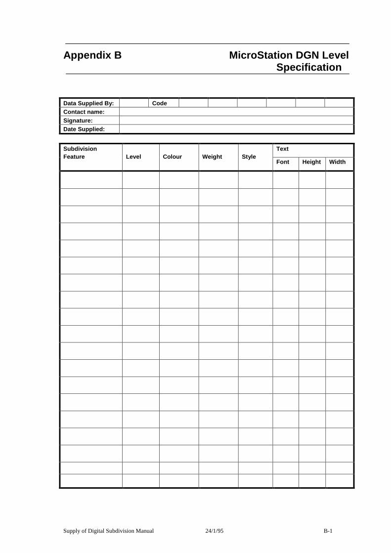
Supply of Digital Subdivision Manual 24/1/95 B-1
Appendix B MicroStation DGN Level
Specification
Data Supplied By: Code Contact name: Signature: Date Supplied:
Text Subdivision Feature
Level
Colour
Weight
Style
Font Height Width

B-2 24/1/95 Supply of Digital Subdivisions Manual

Supply of Digital Subdivision Manual 24/1/95 C-1
Appendix C DXF Layer Specification Data Supplied By: Code Contact name: Signature: Date Supplied:
DXF Layer
Subdivision Feature

C-2 Supply of Digital Subdivisions Manual 24/1/95

Water Supply Digital Input Manual
Second Edition
No.


Copyright Melbourne Water Ltd. 1995 Copyright Yarra Valley Water Ltd. 1995 Copyright South East Water Ltd. 1995 Copyright City West Water Ltd. 1995 All rights reserved. This publication is protected by copyright and is provided under licence. No part of this publication may be reproduced, distributed, transmitted, stored in a retrieval system, or reduced to any electronic medium without the written authority of the Managing Director of the Water Company. The Water Company assumes no responsibility for any errors in or omissions from this document or any damages arising out of the use or inability to use this document. Changes may be made periodically to the information herein. “Intergraph” and “IGDS” are registered trademarks of the Intergraph Corporation. “MicroStation” is a trademark of Bentley Systems Incorporated and an affiliate of Intergraph Corporation. “VAX” is a trademark of Digital Equipment. “UNIX” is a trademark of AT & T Bell Laboratories. “dBASE” is a registered trademark of Ashton-Tate. “PC-DOS” is a registered trademark of International Business Machines Corporation. “INFORMIX” is a registered trademark of Informix Software Incorporated.

Table of Contents
viii
March 1995
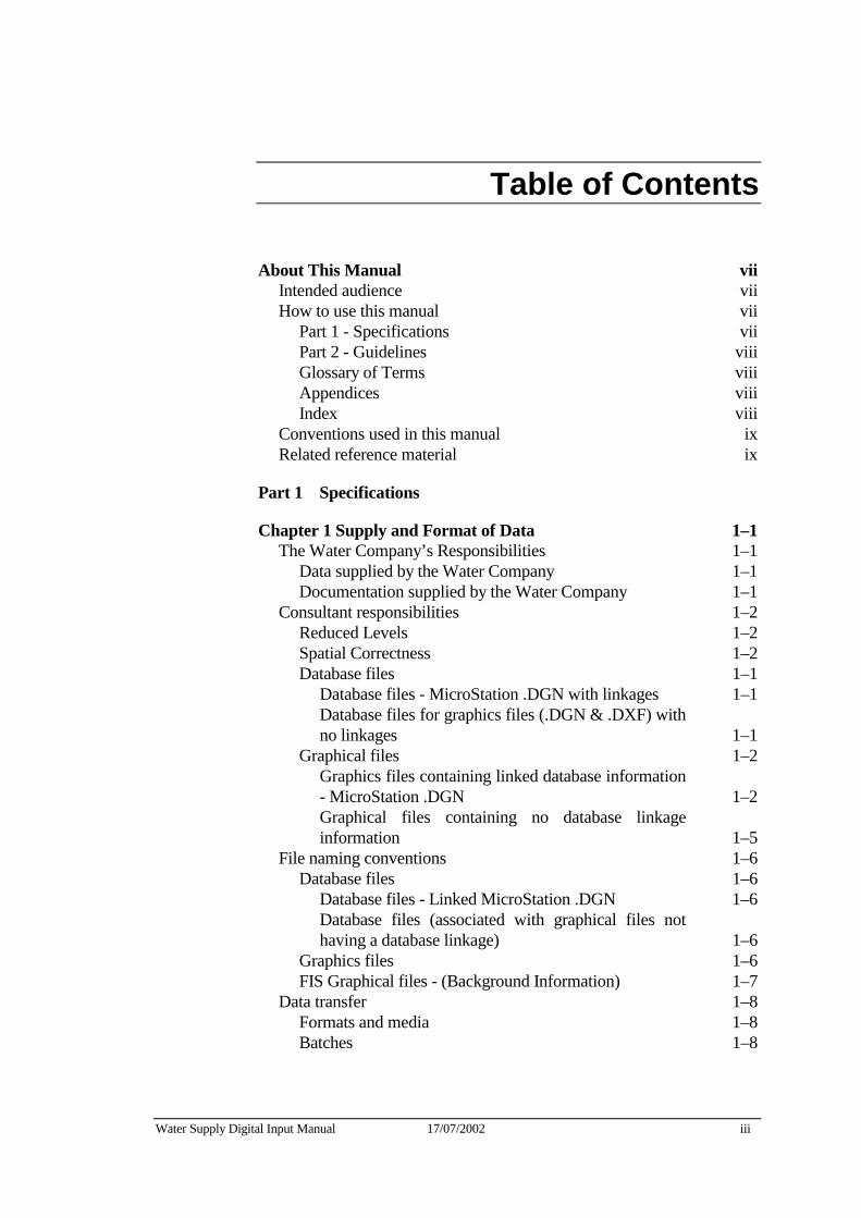
Water Supply Digital Input Manual 17/07/2002 iii
Table of Contents
About This Manual vii Intended audience vii How to use this manual vii
Part 1 - Specifications vii Part 2 - Guidelines viii Glossary of Terms viii Appendices viii Index viii
Conventions used in this manual ix Related reference material ix
Part 1 Specifications
Chapter 1 Supply and Format of Data 1–1 The Water Company’s Responsibilities 1–1
Data supplied by the Water Company 1–1 Documentation supplied by the Water Company 1–1
Consultant responsibilities 1–2 Reduced Levels 1–2 Spatial Correctness 1–2 Database files 1–1
Database files - MicroStation .DGN with linkages 1–1 Database files for graphics files (.DGN & .DXF) with no linkages 1–1
Graphical files 1–2 Graphics files containing linked database information - MicroStation .DGN 1–2 Graphical files containing no database linkage information 1–5
File naming conventions 1–6 Database files 1–6
Database files - Linked MicroStation .DGN 1–6 Database files (associated with graphical files not having a database linkage) 1–6
Graphics files 1–6 FIS Graphical files - (Background Information) 1–7
Data transfer 1–8 Formats and media 1–8 Batches 1–8
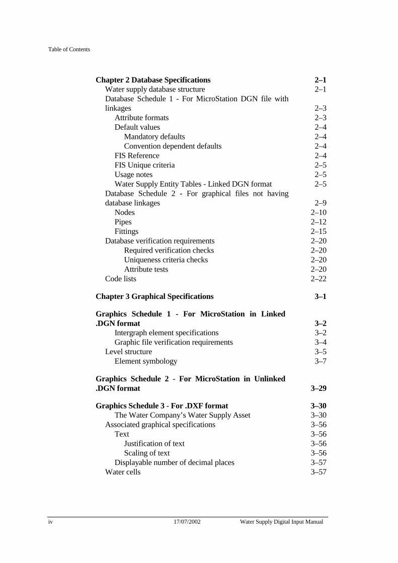
Table of Contents
iv 17/07/2002 Water Supply Digital Input Manual
Chapter 2 Database Specifications 2–1 Water supply database structure 2–1 Database Schedule 1 - For MicroStation DGN file with linkages 2–3
Attribute formats 2–3 Default values 2–4
Mandatory defaults 2–4 Convention dependent defaults 2–4
FIS Reference 2–4 FIS Unique criteria 2–5 Usage notes 2–5 Water Supply Entity Tables - Linked DGN format 2–5
Database Schedule 2 - For graphical files not having database linkages 2–9
Nodes 2–10 Pipes 2–12 Fittings 2–15
Database verification requirements 2–20 Required verification checks 2–20 Uniqueness criteria checks 2–20 Attribute tests 2–20
Code lists 2–22
Chapter 3 Graphical Specifications 3–1
Graphics Schedule 1 - For MicroStation in Linked .DGN format 3–2
Intergraph element specifications 3–2 Graphic file verification requirements 3–4
Level structure 3–5 Element symbology 3–7
Graphics Schedule 2 - For MicroStation in Unlinked .DGN format 3–29
Graphics Schedule 3 - For .DXF format 3–30 The Water Company’s Water Supply Asset 3–30
Associated graphical specifications 3–56 Text 3–56
Justification of text 3–56 Scaling of text 3–56
Displayable number of decimal places 3–57 Water cells 3–57
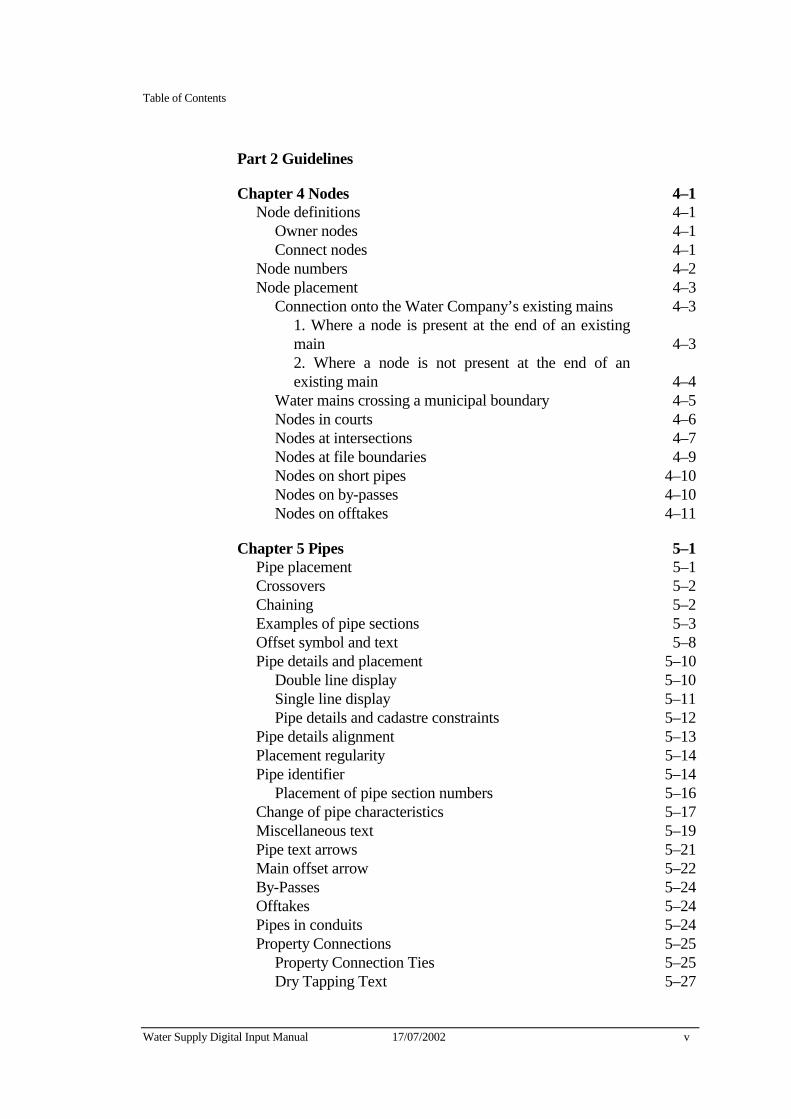
Table of Contents
Water Supply Digital Input Manual 17/07/2002 v
Part 2 Guidelines
Chapter 4 Nodes 4–1 Node definitions 4–1
Owner nodes 4–1 Connect nodes 4–1
Node numbers 4–2 Node placement 4–3
Connection onto the Water Company’s existing mains 4–3 1. Where a node is present at the end of an existing main 4–3 2. Where a node is not present at the end of an existing main 4–4
Water mains crossing a municipal boundary 4–5 Nodes in courts 4–6 Nodes at intersections 4–7 Nodes at file boundaries 4–9 Nodes on short pipes 4–10 Nodes on by-passes 4–10 Nodes on offtakes 4–11
Chapter 5 Pipes 5–1 Pipe placement 5–1 Crossovers 5–2 Chaining 5–2 Examples of pipe sections 5–3 Offset symbol and text 5–8 Pipe details and placement 5–10
Double line display 5–10 Single line display 5–11 Pipe details and cadastre constraints 5–12
Pipe details alignment 5–13 Placement regularity 5–14 Pipe identifier 5–14
Placement of pipe section numbers 5–16 Change of pipe characteristics 5–17 Miscellaneous text 5–19 Pipe text arrows 5–21 Main offset arrow 5–22 By-Passes 5–24 Offtakes 5–24 Pipes in conduits 5–24 Property Connections 5–25
Property Connection Ties 5–25 Dry Tapping Text 5–27
Table of Contents
vi 17/07/2002 Water Supply Digital Input Manual
Scour pipes 5–28 Graphical flags 5–29
Problem graphical flag 5–29 Edgematching graphical flags 5–29 Documentation to be supplied 5–30
Other authority’s water mains 5–30 Abandoned Water Mains 5–30 Aqueducts 5–31 Trunk services (private mains) 5–31 Abandoned Water Mains 5–32 Depth 5–32
Chapter 6 Valves 6–1 Air Valves 6–1 Ferrules 6–1 Shut valves 6–2 Other valves 6–2 Valve number 6–2 Valve placement 6–4 Valves in courts 6–5
Chapter 7 Hydrants 7–1 Ownership of hydrants 7–1 Placement of hydrants 7–1
Hydrants with fittings 7–2 Offset hydrants 7–2 Valve controlled hydrants across mains 7–3
Valve and hydrant text 7–3 Fireplug and washout symbol 7–4 Below Ground hydrants 7–4
Chapter 8 Other Fittings 8–1 Reducers 8–1 Blank ends 8–2 Strainers, swabbing points, chlorination points, scours, pump points and manholes 8–2
Chapter 9 Glossary of Terms 9–1
Appendices
Water Supply Digital Input Manual 17/07/2002 vii
About This Manual This manual details the graphics and non-graphics data specifications required by the Water Company for the digital recording of a constructed water supply service information.
Intended audience This manual defines the requirements and specifications for the supply of digital water supply data to the Water Company by any person or company, hereafter known as the Consultant.
How to use this manual This manual is divided into two parts.
Part 1 - Specifications
Part 1 consists of three chapters which describe the requirements of graphics and non-graphics data.
Chapter 1 Supply and Format of Data
This chapter describes the responsibility of the Water Company and the Consultants with regard to the supply of “as constructed” data and associated documentation. It includes details about the supply and format of all digital data, file naming conventions and database linkage formats.
Chapter 2 Database Specifications
This Chapter describes the non-graphics requirements associated with the graphical elements of the water supply facility. The water supply database structure is described and a schedule of the entities and attributes, default values, uniqueness criteria and attribute format is included. It also contains details of attribute relationships and expected values, which can be used as a basis for database verification checks.
Chapter 3 Graphical Specifications
This chapter describes the graphics data requirements. It includes the level structure, symbology specifications, associated graphics specifications and a graphical library of cells required in water supply data capture.
About This Manual
viii 17/07/2002 Water Supply Digital Input Manual
Part 2 - Guidelines
Part 2 consists of seven chapters which detail the presentation standards association with the graphics input of water supply assets and associated database entry.
Chapters 4 - 8
Chapters 4-10 contain the requirements for the input of the water supply assets listed in Chapter 3. These chapters cover:
✦ nodes,
✦ pipes,
✦ valves,
✦ hydrants,
✦ other water fittings,
✦ recorders,
✦ electrolysis installations.
Glossary of Terms
This chapter contains a glossary of terms used in this manual.
Appendices
The Appendices contain:
✦ Supply of Digital Information Request Form,
✦ sample print-outs of non-graphics (database) files,
✦ a symbology quick reference guide,
✦ sample water supply plot with subdivisional backdrop.
Index
A cross referenced index is included at the back of the manual.
About This Manual
Water Supply Digital Input Manual 17/07/2002 ix
Conventions used in this manual Italics are used when reference is made to information in other chapters of this manual.
For example:
This is shown in the Database schedule in Chapter 2.
Italics are also used to emphasize words or phrases.
✦ Diamond bullets are used for lists of items of topics.
Related reference material Survey Manual

About This Manual
x 17/07/2002 Water Supply Digital Input Manual

Part 1 Specifications


Water Supply Digital Input Manual 27/02/95 1–1
Chapter 1 Supply and Format of Data This chapter describes the formats in which externally captured Water Supply data must be supplied to the Water Company. It describes the responsibilities of the Water Company and associated consultant companies.
The Water Company’s Responsibilities
Data supplied by the Water Company
On request the Water Company will the provide appropriate digital data files:
code lists - filename codelist.dat (ASCII format),
font library - filename fontlib.rsc (MicroStation format),
cell library - filename fiscell.cel (MicroStation format),
- filename watblock.dxf (DXF format of FIS cells),
color Table - filename fiscolour.tbl (MicroStation Users),
seed graphics file - filename basemap.dgn (MicroStation Users),
- filename basemap.dxf (DXF format),
graphics files containing cadastral map base and existing water supply data that are specifically related to the area of development (supplied per development).
Documentation supplied by the Water Company
The Water Company will provide documentation specific to the development area including:
✦ node numbers required to perform the task,
✦ valve numbers required to perform the task,
✦ street name code list numbers,
✦ job number,
✦ record set number for large mains where required.
The above information will be supplied when a request is received from consultant on a “Supply of Digital Information” form. Refer to Appendix A for original.
1 Supply and Format of Data
1–2 Amended 01/07/98 ① Water Supply Digital Input Manual
Consultant responsibilities It is the responsibility of the consultant to supply The Water Company with data in the required format. This can be either in MicroStation .DGN or .DXF formats.
The Water Company uses MicroStation .DGN format graphics files.
.DGN formatted graphics with database linkages are the preferred format that The Water Company would like to receive any digital information.
The order of preference The Water Company would like digital information supplied is:
1. MicroStation .DGN format with linked database information as per Database Schedule 1 in Chapter 2 and Graphics Schedule 1 in Chapter 3.
2. MicroStation .DGN format without linked database information as per Database Schedule 2 in Chapter 2 and Graphics Schedule 2 in Chapter 3.
3. .DXF format without linked database information as per Database Schedule 2 in Chapter 2 and Graphics Schedule 3 in Chapter 3.
.DXF format graphics files have to be converted to MicroStation .DGN format and linked to an ASCII database file by The Water Company to enable them to be merged into the FIS.
It is the responsibility of the consultant to supply The Water Company with data using either of the required formats.
Submissions that are not in accordance with all relevant Water Company specifications and relevant Australian Standards will be returned to the Consultant for review. The Consultant must ensure that non-conforming submissions (digital and non-digital) are resolved and the Works resubmitted to the Water Company within 10 (ten) working days. ①
Reduced Levels
All reduced levels must be to Australian Height Datum (AHD).
Spatial Correctness
All graphical elements are to be orientated to the correct Australian Map Grid (AMG) Zone 55 location.
Water Supply Digital Input Manual 27/02/95 1–1
Database files
Database files - MicroStation .DGN with linkages
All database files supplied to The Water Company must conform to the following specifications:
✦ Data must be supplied as ASCII files,
✦ All files must have fixed record lengths,
✦ All files must have carriage return, line feed record terminators,
✦ Each file must contain all data relating to one specified entity. The entity number must be embedded in the file name. Refer to File naming conventions later in this chapter,
✦ Each record must contain all specified attribute values in the order set out in Database Schedule 1 in Chapter 2,
✦ All integer, Code list and real values must be right justified, all character attribute values are to be left justified,
✦ Attribute values must be supplied in the correct format, as set out in Database Schedule 1 in Chapter 2,
✦ The first attribute of each record must begin in the first character position on a new line,
✦ Attribute fields must be separated by a single blank space,
✦ Records failing to satisfy the attribute and ownership uniqueness criteria will be rejected and may result in a non-conformance being issued,
✦ If the attribute owner unique identifier is followed by the keyword “required”, the value corresponding to the relevant unique identifier in the owner entity field must be supplied.
Refer to Appendix B for examples of database files.
Database files for graphics files (.DGN & .DXF) with no linkages
All database files supplied to The Water Company must conform to the following specifications:
✦ Data files must be supplied in ASCII format (These files can be created by a text editor, word processor or by the use of a spreadsheet),
✦ The ASCII files must not contain special characters or tab settings,
✦ Database information on Nodes, Pipes and Fittings are to be provided in three separate ASCII files, for each graphical area and have the file extensions of .nod .pip and .fit respectively,

1 Supply and Format of Data
1–2 Amended 01/07/98 ① Water Supply Digital Input Manual
✦ The file names must be in accordance with File naming conventions as described later in this chapter,
✦ Each record must contain all specified attribute values as stated in Database schedule 2 in Chapter 2,
✦ The order of each record must be in accordance with Database schedule 2 in Chapter 2,
✦ All integer and real values must be right justified and end in the character position as defined in Database schedule 2 in Chapter 2,
✦ All alphanumeric and derived codes from code list must be left justified and commence in the character position as defined in Database schedule 2 in Chapter 2,
✦ Attribute values must be supplied in the correct format as set out in Database schedule 2 in Chapter 2,
✦ AMG co-ordinates must match the graphical occurrences.
Refer to Appendix C for examples of database files.
Graphical files
Graphics files containing linked database information - MicroStation .DGN
Graphics data must be supplied to The Water Company in one of the following ISFF formats:
✦ MicroStation PC Design Software two dimensional design files (2D), version 3.x or 4.x,
✦ Intergraph Interactive Graphics Design Software (IGDS) two dimensional design files, version 8.8 or later.
The Water Company will supply, upon request, a seed graphics file (basemap.dgn) which must be used as the basis to create subsequent graphics files.
Graphics files must be supplied to The Water Company:
✦ in accordance with the MicroStation .DGN Graphical Schedule 1 in Chapter 3,
✦ with the digital information orientated to the Australian Map Grid (AMG) Zone 55 as defined by the field survey (refer to the Survey Manual),
✦ with file names in accordance with File naming conventions as described later in this Chapter,
✦ with all deleted elements eliminated. A graphics compress must be performed,
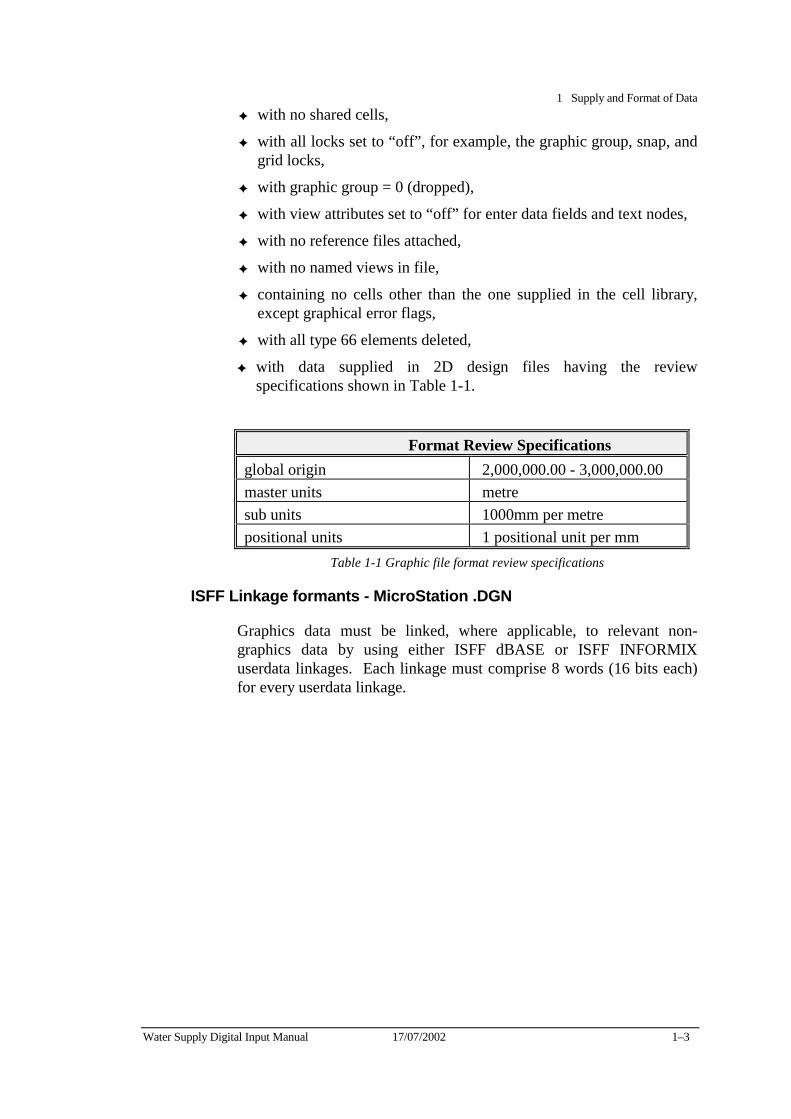
1 Supply and Format of Data
Water Supply Digital Input Manual 17/07/2002 1–3
✦ with no shared cells,
✦ with all locks set to “off”, for example, the graphic group, snap, and grid locks,
✦ with graphic group = 0 (dropped),
✦ with view attributes set to “off” for enter data fields and text nodes,
✦ with no reference files attached,
✦ with no named views in file,
✦ containing no cells other than the one supplied in the cell library, except graphical error flags,
✦ with all type 66 elements deleted,
✦ with data supplied in 2D design files having the review specifications shown in Table 1-1.
Format Review Specifications
global origin 2,000,000.00 - 3,000,000.00 master units metre sub units 1000mm per metre positional units 1 positional unit per mm
Table 1-1 Graphic file format review specifications
ISFF Linkage formants - MicroStation .DGN
Graphics data must be linked, where applicable, to relevant non-graphics data by using either ISFF dBASE or ISFF INFORMIX userdata linkages. Each linkage must comprise 8 words (16 bits each) for every userdata linkage.
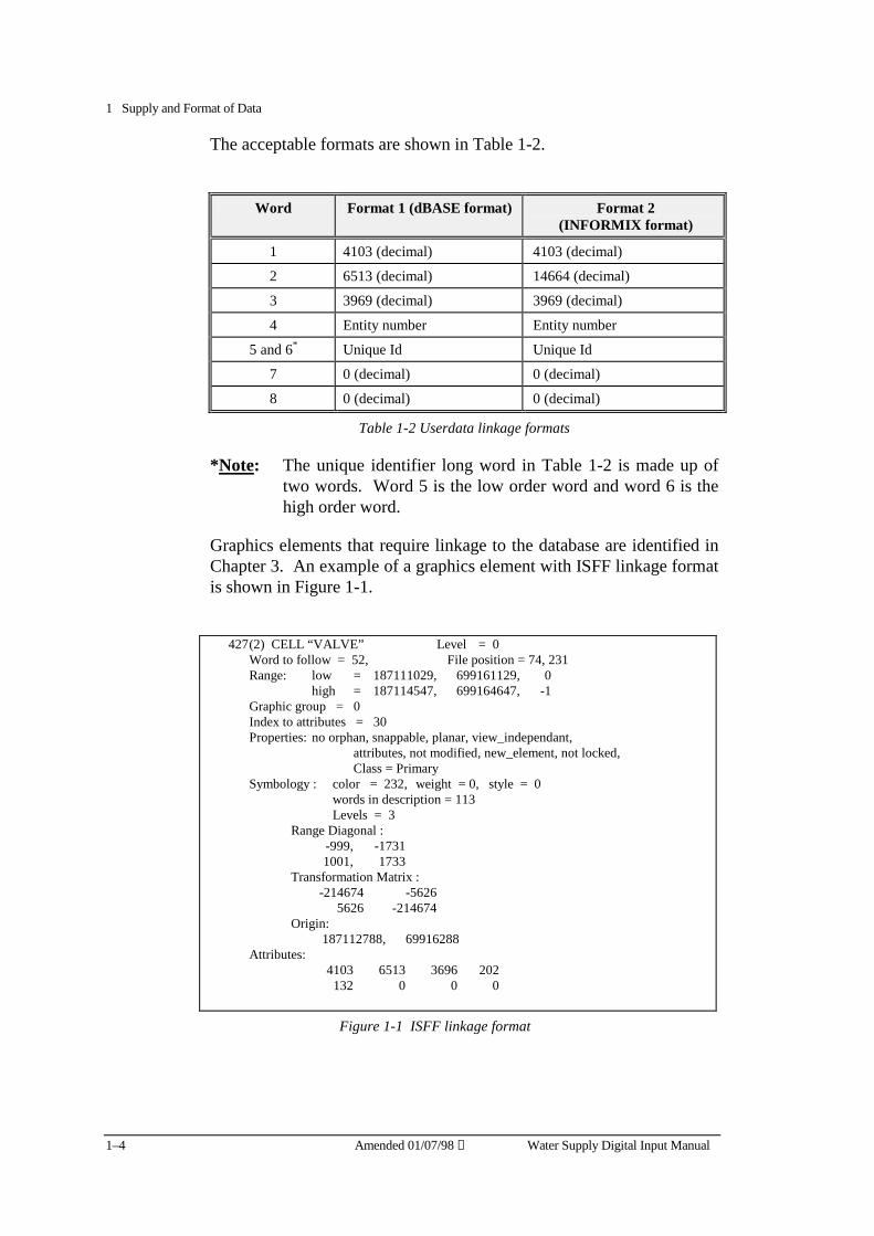
1 Supply and Format of Data
1–4 Amended 01/07/98 ① Water Supply Digital Input Manual
The acceptable formats are shown in Table 1-2.
Word Format 1 (dBASE format) Format 2
(INFORMIX format)
1 4103 (decimal) 4103 (decimal)
2 6513 (decimal) 14664 (decimal)
3 3969 (decimal) 3969 (decimal)
4 Entity number Entity number
5 and 6* Unique Id Unique Id
7 0 (decimal) 0 (decimal)
8 0 (decimal) 0 (decimal)
Table 1-2 Userdata linkage formats
*Note: The unique identifier long word in Table 1-2 is made up of two words. Word 5 is the low order word and word 6 is the high order word.
Graphics elements that require linkage to the database are identified in Chapter 3. An example of a graphics element with ISFF linkage format is shown in Figure 1-1.
427 (2) CELL “VALVE” Level = 0 Word to follow = 52, File position = 74, 231 Range: low = 187111029, 699161129, 0 high = 187114547, 699164647, -1 Graphic group = 0 Index to attributes = 30 Properties: no orphan, snappable, planar, view_independant, attributes, not modified, new_element, not locked, Class = Primary Symbology : color = 232, weight = 0, style = 0 words in description = 113 Levels = 3 Range Diagonal : -999, -1731 1001, 1733 Transformation Matrix : -214674 -5626 5626 -214674 Origin: 187112788, 69916288 Attributes: 4103 6513 3696 202 132 0 0 0
Figure 1-1 ISFF linkage format
1 Supply and Format of Data
Water Supply Digital Input Manual 17/07/2002 1–5
Graphical files containing no database linkage information
1. MICROSTATION FORMAT
Same format as for MicroStation files containing database linkages, except that there must be no userdata linkages.
2. .DXF FORMAT
The digital exchange format (.DXF) must:
✦ Be in accordance with the .DXF Graphical Schedule 3 in Chapter 3
✦ with the digital information orientated to the Australian Map Grid (AMG) Zone 55 as defined by the field survey (refer to the Survey Manual),
✦ contain the data in two dimensional (2D) format,
✦ with file names in accordance with File naming conventions as described later in this Chapter,
✦ not contain blocks other than the ones used by The Water Company, except for graphical error flags,
✦ with a separate graphics file for each graphical area as defined in the municipal index graphics files.
1 Supply and Format of Data
1–6 Amended 01/07/98 ① Water Supply Digital Input Manual
File naming conventions Each job has a ten digit file reference number which is The Water Company’s File Management System (FMS) number.
For example 8012371084. (used for subdivisions)
The file naming convention is to drop the first four digits from the file reference number (eg 8012) and add a two digit number (01, 02, etc) to the end to indicate the stage number of the paricular subdivision,
For example: 37108401.
Database files
Database files - Linked MicroStation .DGN
For database files, the filename must have an extension that relates to the relevant entity number.
For example, 37108401.201 (for water supply pipe sections), 37108401.225 (for water supply node numbers), etc.
Database files (associated with graphical files not having a database linkage)
Database files for Nodes, Pipes and Fittings must have extensions of .nod, .pip and .fit respectively.
For example 37108401.nod, 37108401.pip and 37108401.fit
Graphics files
MicroStation graphics files must have a .WAT extension,
For example, 37108401.WAT
.DXF files must have a .DXF extension,
For example, 37108401.DXF
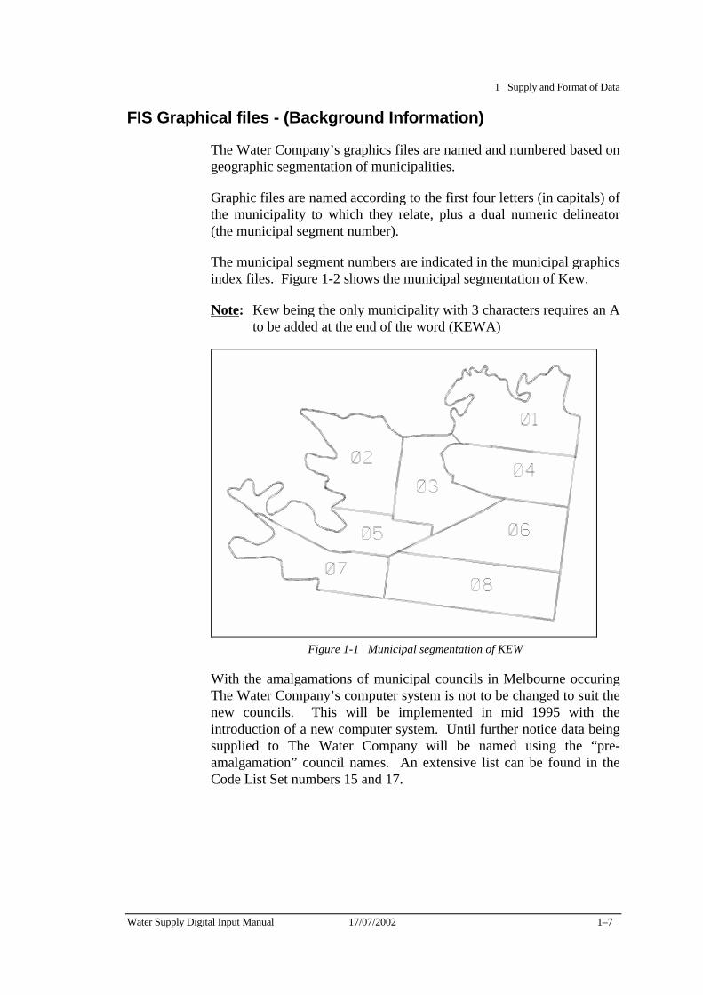
1 Supply and Format of Data
Water Supply Digital Input Manual 17/07/2002 1–7
FIS Graphical files - (Background Information)
The Water Company’s graphics files are named and numbered based on geographic segmentation of municipalities.
Graphic files are named according to the first four letters (in capitals) of the municipality to which they relate, plus a dual numeric delineator (the municipal segment number).
The municipal segment numbers are indicated in the municipal graphics index files. Figure 1-2 shows the municipal segmentation of Kew.
Note: Kew being the only municipality with 3 characters requires an A to be added at the end of the word (KEWA)
Figure 1-1 Municipal segmentation of KEW
With the amalgamations of municipal councils in Melbourne occuring The Water Company’s computer system is not to be changed to suit the new councils. This will be implemented in mid 1995 with the introduction of a new computer system. Until further notice data being supplied to The Water Company will be named using the “pre-amalgamation” council names. An extensive list can be found in the Code List Set numbers 15 and 17.

1 Supply and Format of Data
1–8 Amended 01/07/98 ① Water Supply Digital Input Manual
Data transfer
Formats and media
Data must be delivered in a virus free, non-compressed or non-zipped format, to the Water Company on the following medium.
✦ PC DOS dataset, where:
− the media is a 3.5″ double sided high density diskette
The information must not be supplied in a compressed or zipped format.
Other formats will not be accepted unless previously arranged with the Water Company.
Batches
All data relating to one job must appear where practicable on a single diskette. However when a job crosses municipal boundaries, the data for each municipality must be supplied on a separate media.
Only one job and one discipline (ie water, not sewer) is to be supplied on one media (eg diskette). Additional jobs and/or disciplines are to be supplied on separate media.
A batch of data must contain at least one graphics file and all applicable database files. Database files containing no records are not required.
Mapbase graphics are not to be included.
Documentation which indicates the following, must accompany each batch of data:
✦ a listing of files contained on the media.
✦ the manner in which data was written to the media.
✦ how the data should be retrieved.
✦ the municipality and FIS file number(s).
✦ a plot at scale 1:1000 of the graphical file including mapbase.
✦ the total length of water mains in the project,
Water Supply Digital Input Manual 17/07/02 2–1
Chapter 2 Database Specifications The Water Company’s water supply database is made up of a number of entities. An entity is a database Table consisting of a number of attributes. These attributes describe different aspects of the entity.
For example, a pipe is an entity (number 201). The pipes material type, size, date of construction etc are some of it’s attributes.
Each entity in the water supply database has a unique number and each attribute of that entity is identified by a field name.
For example, entity 225 - Nodes have five attributes:
✦ a unique identifier,
✦ a municipality,
✦ a node number,
✦ an X co-ordinate (Easting),
✦ a Y co-ordinate (Northing).
A database Table can be seen as a set of rows and columns. The attributes are the columns of the table. The rows are the actual occurrences that are stored in the table.
Water supply database structure The Water Company’s water supply database is structured so that most entities are linked to other entities in the database structure using a unique identifier.
For example:
✦ The Nodes entity (225) is the owner of the Pipe Section entity (201) which in turn is the owner of the Valves entity (202).
The water supply database structure is shown in Figure 2-1.
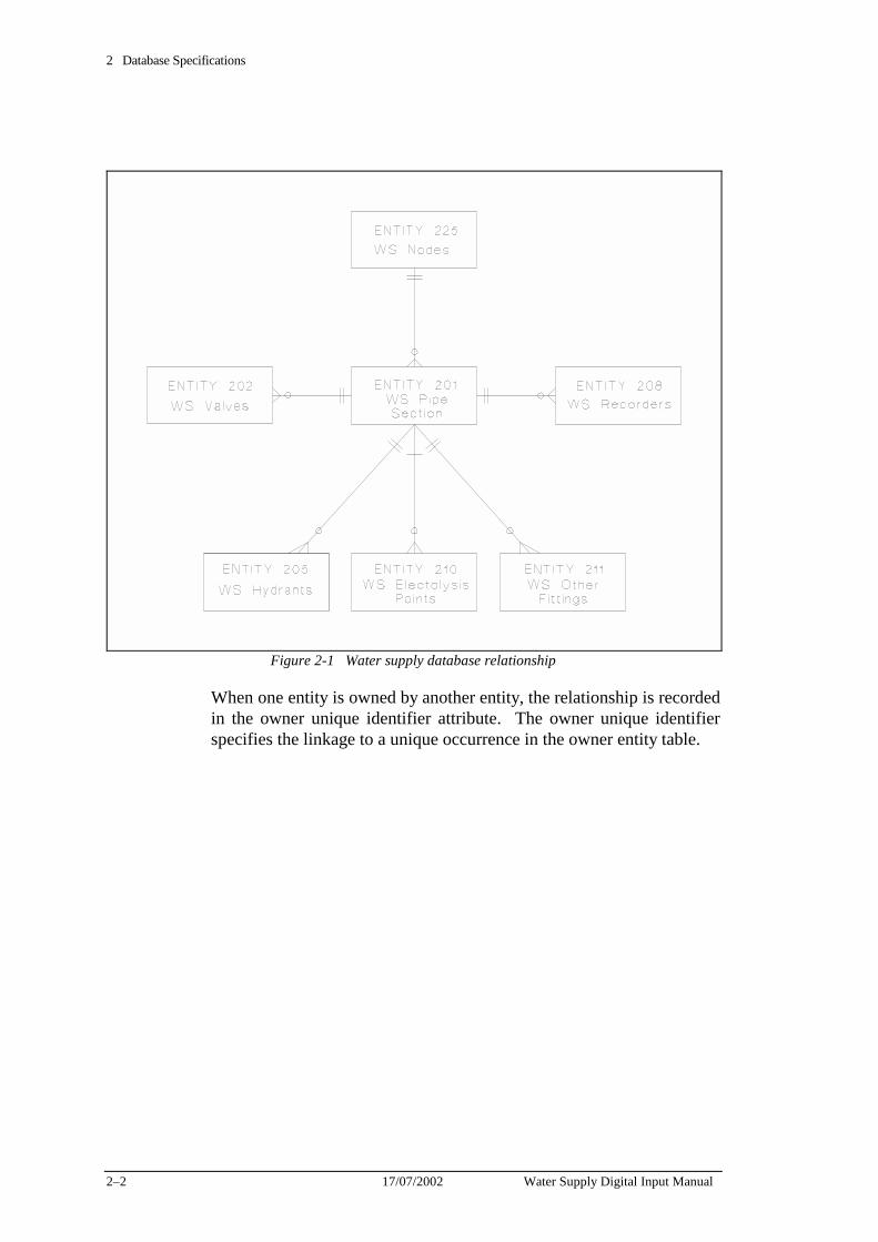
2 Database Specifications
2–2 17/07/2002 Water Supply Digital Input Manual
Figure 2-1 Water supply database relationship
When one entity is owned by another entity, the relationship is recorded in the owner unique identifier attribute. The owner unique identifier specifies the linkage to a unique occurrence in the owner entity table.
2 Database Specifications
Water Supply Digital Input Manual 17/07/2002 2–3
Database Schedule 1 - For MicroStation DGN file with linkages
The following schedule describes the specifications of the database entities and attributes that are required by the Water Company.
Each of the tables in this schedule are set out to indicate information required, they have seven columns:
✦ attribute number,
✦ attribute name,
✦ attribute format,
✦ attribute default value - mandatory,
✦ attribute FIS references,
✦ whether the attribute must be unique,
✦ usage notes.
Attribute formats
The format of the attributes in the database schedule are as follows:
✦ the first character of the format string is the attribute type:
− I = integer
− C = integer derived from to the FIS code list
− F = floating point (real) number
− A = alphanumeric character
✦ the remainder of the format string refers to the field width and the number of decimal places for real numbers.
For example:
• I10 indicates that the attribute value must be an integer of up to ten characters. The field must be 10 characters wide and right justified.
• F8.3 indicates that the attribute value must be a floating point number with up to four numbers before the decimal point and up to three numbers following the decimal point. The field must be eight characters wide including the decimal point and right justified.
• A3 indicates that the attribute value must be alphanumeric and up to three characters wide. The field must be 3 characters wide and left justified.
2 Database Specifications
2–4 17/07/2002 Water Supply Digital Input Manual
• C5 indicates that the attribute value must be a code list entry and up to five characters wide. The field must be five characters wide and right justified.
Attribute format values that are not applicable must be filled with blank spaces i.e. the fields must contain the correct number of characters.
Default values
There are two types of default values listed in the database schedule:
Mandatory defaults
Mandatory defaults are attribute values that are required by the database and link entities.
For example: the water supply valve owner entity number must = 201
The omission of mandatory defaults can cause the Water Company’s software procedures to fail and may result in non-conformances being issued.
Convention dependent defaults
Convention dependent defaults must be used to maintain the consistency of database records.
For example: if the water supply valve status is not otherwise known, then a value of 6 (active) should be supplied.
FIS Reference
The FIS reference column in the database schedule provides four types of reference, which are defined as follows:
✦ AN(nn) indicates that the attribute:
− is an alphanumeric field nn characters wide, where nn equals the number specified in the format field.
− has an alphanumeric reference designated by the Water Company’s Facilities Information System (FIS).
✦ C(nnn) or C(nnn)/C(mmm) indicates that the attribute is derived from code list (nnn) and/or code list (mmm). Refer to Code lists later in this chapter.
✦ I(nnnnn) indicates the maximum value allowed for integer values in the FIS database.
✦ F indicates that the attribute value is a floating point number
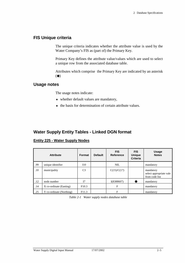
2 Database Specifications
Water Supply Digital Input Manual 17/07/2002 2–5
FIS Unique criteria
The unique criteria indicates whether the attribute value is used by the Water Company’s FIS as (part of) the Primary Key.
Primary Key defines the attribute value/values which are used to select a unique row from the associated database table.
Attributes which comprise the Primary Key are indicated by an asterisk (❋❋❋❋ )
Usage notes
The usage notes indicate:
✦ whether default values are mandatory,
✦ the basis for determination of certain attribute values.
Water Supply Entity Tables - Linked DGN format
Entity 225 - Water Supply Nodes
Attribute
Format
Default
FIS Reference
FIS Unique Criteria
Usage Notes
.99 unique identifier I10 NIL mandatory
.10 municipality C3 C(15)/C(17) mandatory select appropriate vale from code list
.12 node number I7 I(8388607) ❋❋❋❋ mandatory
.14 X co-ordinate (Easting) F10.3 F mandatory
.25 Y co-ordinate (Northing) F11.3 F mandatory
Table 2-1 Water supply nodes database table
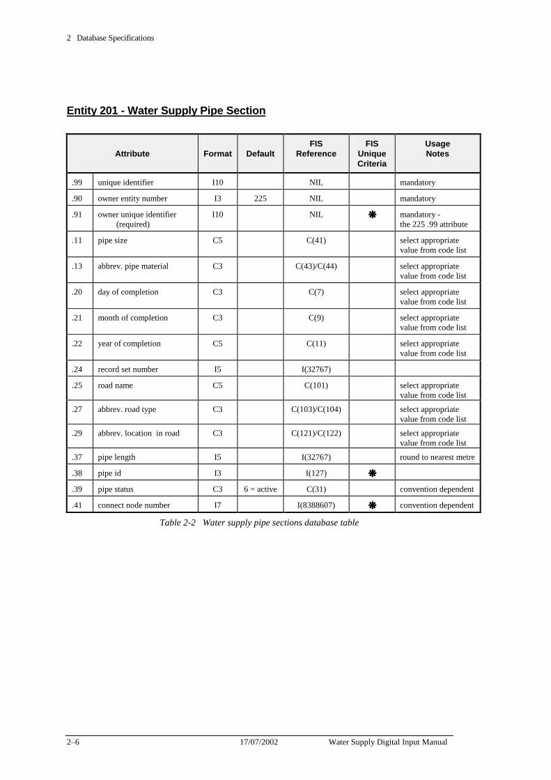
2 Database Specifications
2–6 17/07/2002 Water Supply Digital Input Manual
Entity 201 - Water Supply Pipe Section
Attribute
Format
Default
FIS Reference
FIS Unique Criteria
Usage Notes
.99 unique identifier I10 NIL mandatory
.90 owner entity number I3 225 NIL mandatory
.91 owner unique identifier (required)
I10 NIL ❋❋❋❋ mandatory - the 225 .99 attribute
.11 pipe size C5 C(41) select appropriate value from code list
.13 abbrev. pipe material C3 C(43)/C(44) select appropriate value from code list
.20 day of completion C3 C(7) select appropriate value from code list
.21 month of completion C3 C(9) select appropriate value from code list
.22 year of completion C5 C(11) select appropriate value from code list
.24 record set number I5 I(32767)
.25 road name C5 C(101) select appropriate value from code list
.27 abbrev. road type C3 C(103)/C(104) select appropriate value from code list
.29 abbrev. location in road C3 C(121)/C(122) select appropriate value from code list
.37 pipe length I5 I(32767) round to nearest metre
.38 pipe id I3 I(127) ❋❋❋❋
.39 pipe status C3 6 = active C(31) convention dependent
.41 connect node number I7 I(8388607) ❋❋❋❋ convention dependent
Table 2-2 Water supply pipe sections database table
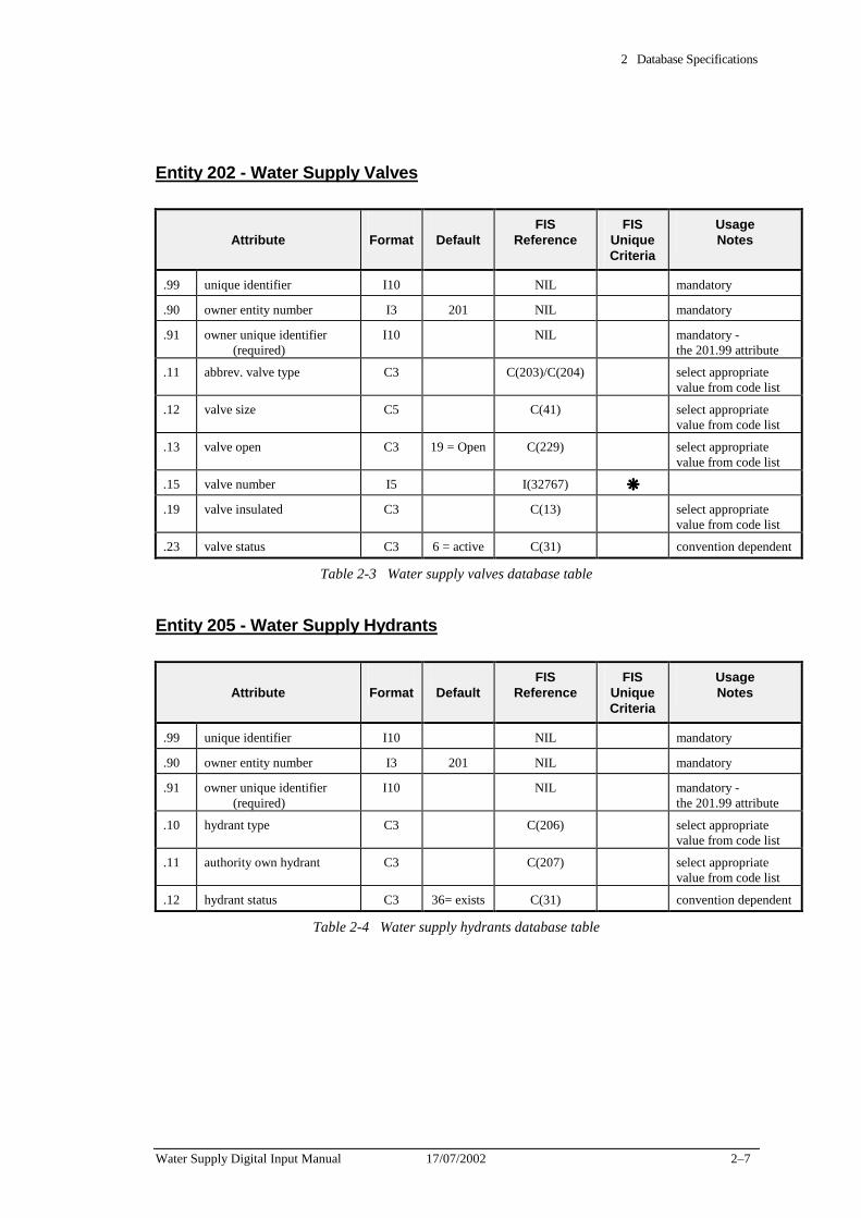
2 Database Specifications
Water Supply Digital Input Manual 17/07/2002 2–7
Entity 202 - Water Supply Valves
Attribute
Format
Default
FIS Reference
FIS Unique Criteria
Usage Notes
.99 unique identifier I10 NIL mandatory
.90 owner entity number I3 201 NIL mandatory
.91 owner unique identifier (required)
I10 NIL mandatory - the 201.99 attribute
.11 abbrev. valve type C3 C(203)/C(204) select appropriate value from code list
.12 valve size C5 C(41) select appropriate value from code list
.13 valve open C3 19 = Open C(229) select appropriate value from code list
.15 valve number I5 I(32767) ❋❋❋❋
.19 valve insulated C3 C(13) select appropriate value from code list
.23 valve status C3 6 = active C(31) convention dependent
Table 2-3 Water supply valves database table
Entity 205 - Water Supply Hydrants
Attribute
Format
Default
FIS Reference
FIS Unique Criteria
Usage Notes
.99 unique identifier I10 NIL mandatory
.90 owner entity number I3 201 NIL mandatory
.91 owner unique identifier (required)
I10 NIL mandatory - the 201.99 attribute
.10 hydrant type C3 C(206) select appropriate value from code list
.11 authority own hydrant C3 C(207) select appropriate value from code list
.12 hydrant status C3 36= exists C(31) convention dependent
Table 2-4 Water supply hydrants database table
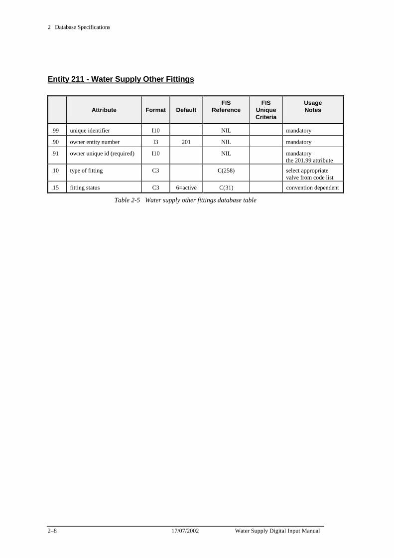
2 Database Specifications
2–8 17/07/2002 Water Supply Digital Input Manual
Entity 211 - Water Supply Other Fittings
Attribute
Format
Default
FIS Reference
FIS Unique Criteria
Usage Notes
.99 unique identifier I10 NIL mandatory
.90 owner entity number I3 201 NIL mandatory
.91 owner unique id (required) I10 NIL mandatory the 201.99 attribute
.10 type of fitting C3 C(258) select appropriate valve from code list
.15 fitting status C3 6=active C(31) convention dependent
Table 2-5 Water supply other fittings database table
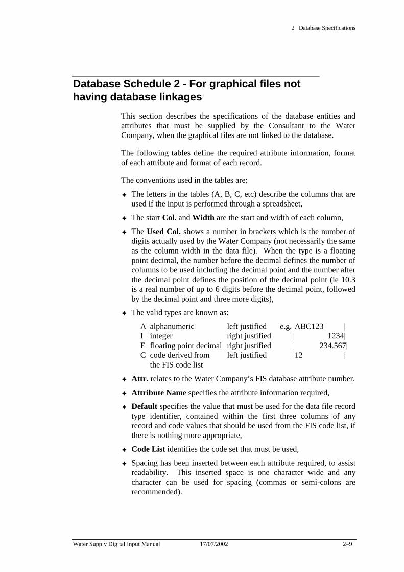
2 Database Specifications
Water Supply Digital Input Manual 17/07/2002 2–9
Database Schedule 2 - For graphical files not having database linkages
This section describes the specifications of the database entities and attributes that must be supplied by the Consultant to the Water Company, when the graphical files are not linked to the database.
The following tables define the required attribute information, format of each attribute and format of each record.
The conventions used in the tables are:
✦ The letters in the tables (A, B, C, etc) describe the columns that are used if the input is performed through a spreadsheet,
✦ The start Col. and Width are the start and width of each column,
✦ The Used Col. shows a number in brackets which is the number of digits actually used by the Water Company (not necessarily the same as the column width in the data file). When the type is a floating point decimal, the number before the decimal defines the number of columns to be used including the decimal point and the number after the decimal point defines the position of the decimal point (ie 10.3 is a real number of up to 6 digits before the decimal point, followed by the decimal point and three more digits),
✦ The valid types are known as:
A alphanumeric left justified e.g. |ABC123 | I integer right justified | 1234| F floating point decimal right justified | 234.567| C code derived from left justified |12 | the FIS code list
✦ Attr. relates to the Water Company’s FIS database attribute number,
✦ Attribute Name specifies the attribute information required,
✦ Default specifies the value that must be used for the data file record type identifier, contained within the first three columns of any record and code values that should be used from the FIS code list, if there is nothing more appropriate,
✦ Code List identifies the code set that must be used,
✦ Spacing has been inserted between each attribute required, to assist readability. This inserted space is one character wide and any character can be used for spacing (commas or semi-colons are recommended).
2 Database Specifications
2–10 17/07/2002 Water Supply Digital Input Manual
The water supply ASCII data must be supplied in three separate files:
1. Nodes - containing all node information (filename.nod),
2. pipes - containing all pipe information (filename.pip),
3. fittings - containing all fittings information (filename.fit).
Nodes
The nodes ASCII file (filename.nod) contains two record types.
1. The first row contains the Node header,
2. The second and following rows contain the node descriptions.
For example:
The order of record types within the node ASCII file is as follows:
Record Type Record Type Description:
1 Node Header
2 Node Description
2 Node Description
2 Node Description
Unique criteria: Node numbers must be unique within each municipality.
Note: All fields must be filled, excepting those reserved by the Water Company.
The owner node must appear in graphics and in the ASCII file for the linkage process to work.
Tables 2-6 to 2-7 set out the required formats
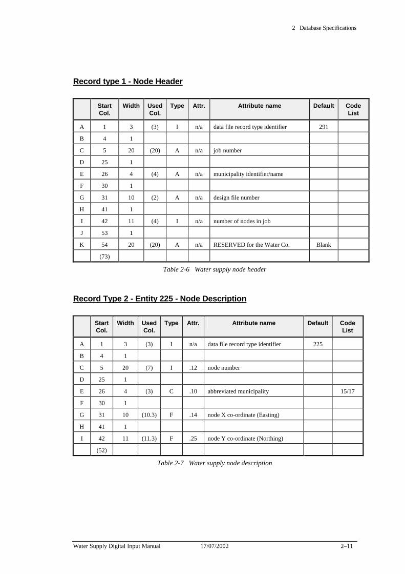
2 Database Specifications
Water Supply Digital Input Manual 17/07/2002 2–11
Record type 1 - Node Header
Start Col.
Width Used Col.
Type Attr. Attribute name Default Code List
A 1 3 (3) I n/a data file record type identifier 291
B 4 1
C 5 20 (20) A n/a job number
D 25 1
E 26 4 (4) A n/a municipality identifier/name
F 30 1
G 31 10 (2) A n/a design file number
H 41 1
I 42 11 (4) I n/a number of nodes in job
J 53 1
K 54 20 (20) A n/a RESERVED for the Water Co. Blank
(73)
Table 2-6 Water supply node header
Record Type 2 - Entity 225 - Node Description
Start Col.
Width Used Col.
Type Attr. Attribute name Default Code List
A 1 3 (3) I n/a data file record type identifier 225
B 4 1
C 5 20 (7) I .12 node number
D 25 1
E 26 4 (3) C .10 abbreviated municipality 15/17
F 30 1
G 31 10 (10.3) F .14 node X co-ordinate (Easting)
H 41 1
I 42 11 (11.3) F .25 node Y co-ordinate (Northing)
(52)
Table 2-7 Water supply node description
2 Database Specifications
2–12 17/07/2002 Water Supply Digital Input Manual
Pipes
The pipes ASCII file (filename.pip) contains two record types.
1. The first row contains the Pipe header,
2. The second and following rows contain the pipe descriptions.
For example:
The order of record types within the pipe ASCII file is as follows:
Record Type Record Type Description:
1 Pipe Header
2 Pipe Description
2 Pipe Description
2 Pipe Description
Unique criteria: The concatenation (grouping) of owner node, connect node and pipe section number (pipe ID) must be unique.
Note: All fields must be filled, excepting those reserved by the Water Company.
Tables 2-8 to 2-9 set out the required formats
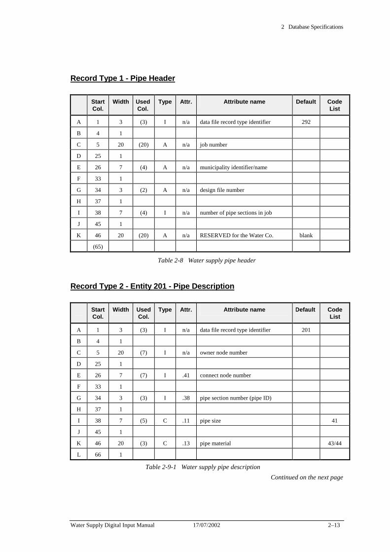
2 Database Specifications
Water Supply Digital Input Manual 17/07/2002 2–13
Record Type 1 - Pipe Header
Start Col.
Width Used Col.
Type Attr. Attribute name Default Code List
A 1 3 (3) I n/a data file record type identifier 292
B 4 1
C 5 20 (20) A n/a job number
D 25 1
E 26 7 (4) A n/a municipality identifier/name
F 33 1
G 34 3 (2) A n/a design file number
H 37 1
I 38 7 (4) I n/a number of pipe sections in job
J 45 1
K 46 20 (20) A n/a RESERVED for the Water Co. blank
(65)
Table 2-8 Water supply pipe header
Record Type 2 - Entity 201 - Pipe Description
Start Col.
Width Used Col.
Type Attr. Attribute name Default Code List
A 1 3 (3) I n/a data file record type identifier 201
B 4 1
C 5 20 (7) I n/a owner node number
D 25 1
E 26 7 (7) I .41 connect node number
F 33 1
G 34 3 (3) I .38 pipe section number (pipe ID)
H 37 1
I 38 7 (5) C .11 pipe size 41
J 45 1
K 46 20 (3) C .13 pipe material 43/44
L 66 1
Table 2-9-1 Water supply pipe description Continued on the next page
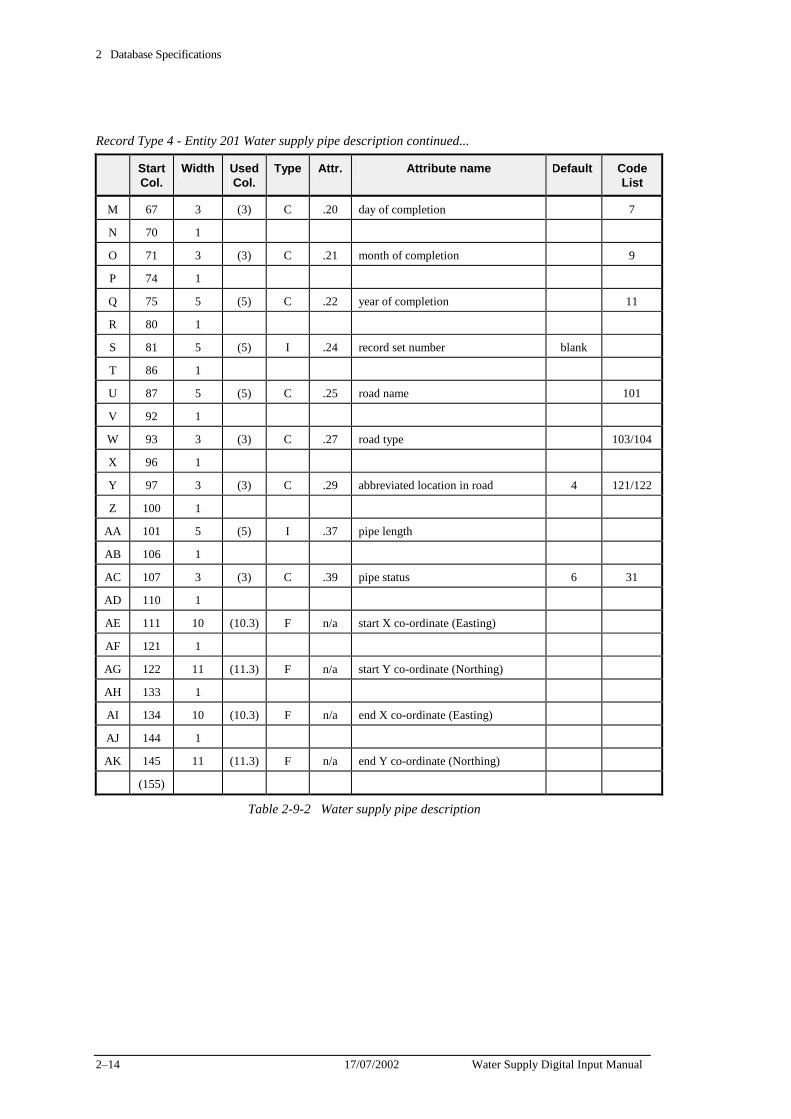
2 Database Specifications
2–14 17/07/2002 Water Supply Digital Input Manual
Record Type 4 - Entity 201 Water supply pipe description continued...
Start Col.
Width Used Col.
Type Attr. Attribute name Default Code List
M 67 3 (3) C .20 day of completion 7
N 70 1
O 71 3 (3) C .21 month of completion 9
P 74 1
Q 75 5 (5) C .22 year of completion 11
R 80 1
S 81 5 (5) I .24 record set number blank
T 86 1
U 87 5 (5) C .25 road name 101
V 92 1
W 93 3 (3) C .27 road type 103/104
X 96 1
Y 97 3 (3) C .29 abbreviated location in road 4 121/122
Z 100 1
AA 101 5 (5) I .37 pipe length
AB 106 1
AC 107 3 (3) C .39 pipe status 6 31
AD 110 1
AE 111 10 (10.3) F n/a start X co-ordinate (Easting)
AF 121 1
AG 122 11 (11.3) F n/a start Y co-ordinate (Northing)
AH 133 1
AI 134 10 (10.3) F n/a end X co-ordinate (Easting)
AJ 144 1
AK 145 11 (11.3) F n/a end Y co-ordinate (Northing)
(155)
Table 2-9-2 Water supply pipe description
2 Database Specifications
Water Supply Digital Input Manual 17/07/2002 2–15
Fittings
The fittings ASCII file (filename.fit) contains four record types.
1. The first row contains the Fittings header,
2. The second and following rows contain the Valves, Hydrants and Other Fittings descriptions.
For example:
The order of record types within the fittings ASCII file is as follows:
Record Type Record Type Description: 1 Fittings Header
2 Valves Description
2 Valves Description
″ ″ ″
″ ″ ″
3 Hydrants Description
3 Hydrants Description
″ ″ ″
″ ″ ″
4 Other Fittings Description
4 Other Fittings Description
″ ″ ″ ″
″ ″ ″ ″
Unique criteria: Valve numbers must be unique within each municipality.
Note: All fields must be filled, excepting those reserved by the Water Company.
Tables 2-10 to 2-13 set out the required formats

2 Database Specifications
2–16 17/07/2002 Water Supply Digital Input Manual
Record Type 1 - Fittings Header
Start Col.
Width Used Col.
Type Attr. Attribute name Default Code List
A 1 3 (3) I n/a data file record type identifier 293
B 4 1
C 5 20 (20) A n/a job number
D 25 1
E 26 10 (4) A n/a municipality identifier/name
F 36 1
G 37 3 (2) A n/a design file number
H 40 1
I 41 4 (4) I n/a number of valves in job
J 45 1
K 46 5 (4) I n/a number of hydrants in job
L 51 1
M 52 10 (4) I n/a number of other fittings in job
(61)
Table 2-10 Water supply fittings header

2 Database Specifications
Water Supply Digital Input Manual 17/07/2002 2–17
Record Type 2 - Entity 202 - Valves Description
Start Col.
Width Used Col.
Type Attr. Attribute name Default Code List
A 1 3 (3) I n/a data file record type identifier 202
B 4 1
C 5 20 (7) I n/a owner node number
D 25 1
E 26 10 (7) I n/a connect node number
F 36 1
G 37 3 (3) I n/a pipe section number (pipe ID)
H 40 1
I 41 4 (3) C .11 valve type 203/204
J 45 1
K 46 5 (5) C .12 valve size 41
L 51 l
M 52 10 (3) C .13 valve open 229
N 62 1
O 63 11 (5) I .15 valve no.
P 74 1
Q 75 11 (3) C .19 valve insulated 13
R 86 1
S 87 3 (3) C .23 valve status 6 31
T 90 1
U 91 10 (10.3) F n/a valve X co-ordinate (Easting)
V 101 1
W 102 11 (11.3) F n/a valve Y co-ordinate (Northing)
(112)
Table 2-11 Water supply valves description
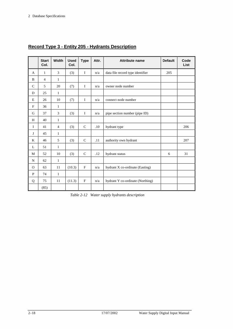
2 Database Specifications
2–18 17/07/2002 Water Supply Digital Input Manual
Record Type 3 - Entity 205 - Hydrants Description
Start Col.
Width Used Col.
Type Attr. Attribute name Default Code List
A 1 3 (3) I n/a data file record type identifier 205
B 4 1
C 5 20 (7) I n/a owner node number
D 25 1
E 26 10 (7) I n/a connect node number
F 36 1
G 37 3 (3) I n/a pipe section number (pipe ID)
H 40 1
I 41 4 (3) C .10 hydrant type 206
J 45 1
K 46 5 (3) C .11 authority own hydrant 207
L 51 l
M 52 10 (3) C .12 hydrant status 6 31
N 62 1
O 63 11 (10.3) F n/a hydrant X co-ordinate (Easting)
P 74 1
Q 75 11 (11.3) F n/a hydrant Y co-ordinate (Northing)
(85)
Table 2-12 Water supply hydrants description
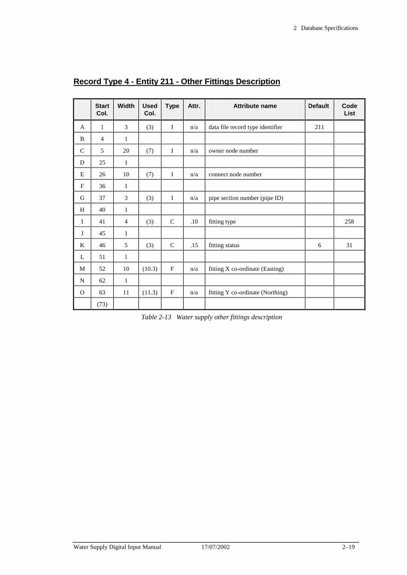
2 Database Specifications
Water Supply Digital Input Manual 17/07/2002 2–19
Record Type 4 - Entity 211 - Other Fittings Description
Start Col.
Width Used Col.
Type Attr. Attribute name Default Code List
A 1 3 (3) I n/a data file record type identifier 211
B 4 1
C 5 20 (7) I n/a owner node number
D 25 1
E 26 10 (7) I n/a connect node number
F 36 1
G 37 3 (3) I n/a pipe section number (pipe ID)
H 40 1
I 41 4 (3) C .10 fitting type 258
J 45 1
K 46 5 (3) C .15 fitting status 6 31
L 51 l
M 52 10 (10.3) F n/a fitting X co-ordinate (Easting)
N 62 1
O 63 11 (11.3) F n/a fitting Y co-ordinate (Northing)
(73)
Table 2-13 Water supply other fittings description
2 Database Specifications
2–20 17/07/2002 Water Supply Digital Input Manual
Database verification requirements Required verification checks
Database attributes must be verified to ensure data accuracy.
These checks may be carried out at the point of data entry, or at output stage.
The following suggestions are offered as a means of checking a number of attributes.
Uniqueness criteria checks
These checks will ensure that the following numbers are unique:
✦ node numbers within a municipality,
✦ valve numbers within a municipality,
✦ pipe identification numbers within a municipality.
Attribute tests
Table 2-14 provides a set of guidelines which may be taken into consideration when verifying database entries.
The Table has been supplied as a basis for the development of additional software certification checks.
Unless otherwise stated, the “expected attribute values” may be varied depending on the municipality or area.
There should not be any values such as Unknown, * or blank.
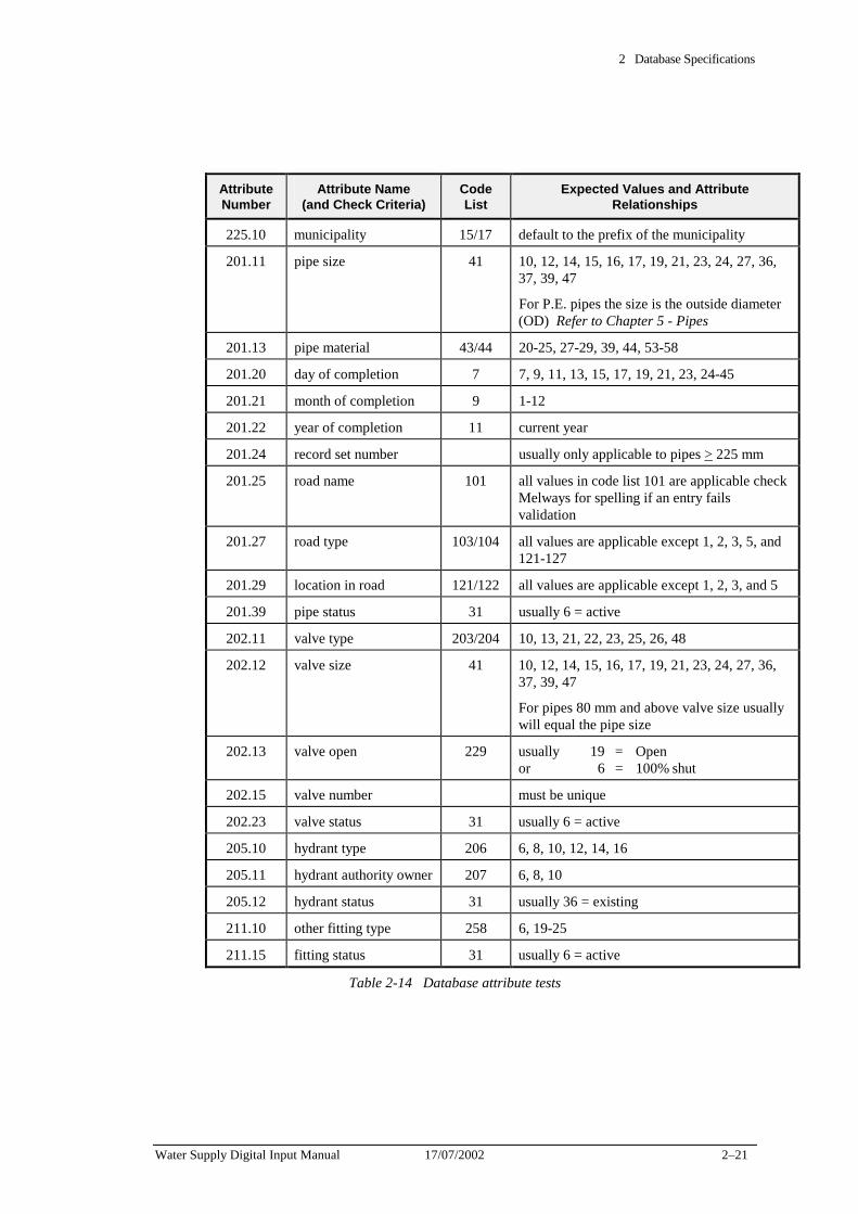
2 Database Specifications
Water Supply Digital Input Manual 17/07/2002 2–21
Attribute Number
Attribute Name (and Check Criteria)
Code List
Expected Values and Attribute Relationships
225.10 municipality 15/17 default to the prefix of the municipality
201.11 pipe size 41 10, 12, 14, 15, 16, 17, 19, 21, 23, 24, 27, 36, 37, 39, 47
For P.E. pipes the size is the outside diameter (OD) Refer to Chapter 5 - Pipes
201.13 pipe material 43/44 20-25, 27-29, 39, 44, 53-58
201.20 day of completion 7 7, 9, 11, 13, 15, 17, 19, 21, 23, 24-45
201.21 month of completion 9 1-12
201.22 year of completion 11 current year
201.24 record set number usually only applicable to pipes > 225 mm
201.25 road name 101 all values in code list 101 are applicable check Melways for spelling if an entry fails validation
201.27 road type 103/104 all values are applicable except 1, 2, 3, 5, and 121-127
201.29 location in road 121/122 all values are applicable except 1, 2, 3, and 5
201.39 pipe status 31 usually 6 = active
202.11 valve type 203/204 10, 13, 21, 22, 23, 25, 26, 48
202.12 valve size 41 10, 12, 14, 15, 16, 17, 19, 21, 23, 24, 27, 36, 37, 39, 47
For pipes 80 mm and above valve size usually will equal the pipe size
202.13 valve open 229 usually 19 = Open or 6 = 100% shut
202.15 valve number must be unique
202.23 valve status 31 usually 6 = active
205.10 hydrant type 206 6, 8, 10, 12, 14, 16
205.11 hydrant authority owner 207 6, 8, 10
205.12 hydrant status 31 usually 36 = existing
211.10 other fitting type 258 6, 19-25
211.15 fitting status 31 usually 6 = active
Table 2-14 Database attribute tests

2 Database Specifications
2–22 17/07/2002 Water Supply Digital Input Manual
Code lists Code list entries are used to standardise terminology by providing a range of item descriptions relating to a particular attribute.
A number of attributes specified in the database schedules require the input of a code list entry number.
In some cases the same code list entry number can be specified for more than one attribute. For example, code list entry number 9 from code list number 43/44 indicates the material concrete (not known if reinforced). This material may be used to define several attributes, as indicated in the database schedule.
Code list entries are constantly reviewed by the Water Company and additions and amendments are made as the need arises. If these is no code list entry that accurately describes a particular attribute and a new one is required please contact the Water Company.
New code list entry numbers must not be assumed and must be validated.
Table 2-15 details the code lists applicable to water supply data capture.

2 Database Specifications
Water Supply Digital Input Manual 17/07/2002 2–23
Code List Code List Description
7 date of completion - day
9 date of completion - month
11 date of completion - year
13 valves insulated
15 municipal names
17 municipal numbers
31 operational status
41 conduit and access point size
43 conduit material
44 conduit material (abbreviated)
71 gauging devices
101 street names
103 street types
104 street types (abbreviated)
121 location in road
122 location in road (abbreviated)
203 valve types
204 valve types (abbreviated)
206 hydrant type
207 hydrant authority owner
229 valve - open
241 recorder number (pressure, flow)
242 recorder numbers (pressure, flow) abbreviated
243 types of gauging devices
258 other fitting type
Table 2-15 Relevant Water Supply Code Lists

2 Database Specifications
2–24 17/07/2002 Water Supply Digital Input Manual
Water Supply Digital Input Manual 17/07/2002 3–1
Chapter 3 Graphical Specifications This Chapter contains the specifications for the graphical representation of elements in water files. It includes:
✦ verification requirements for graphics files,
✦ a level and layer structure for water elements
✦ symbology for water elements
✦ associated software specifications
✦ a graphical library of cells used in water data capture
The Water Company uses Intergraph .DGN format graphics files. The information is stored in each graphics file in levels, or layers, enabling different types of information to be displayed at any one time.
Certain graphical elements have a link to the FIS database.
Each graphics file has 63 levels.
.DGN formatted graphics as set out in the tables in this chapter are the preferred format that The Water Company would like to receive any graphical information.
The order of preference The Water Company would like digital information supplied is:
1. MicroStation .DGN format with linked database information as per Database Schedule 1 in Chapter 2.
2. MicroStation .DGN format without linked database information as per Database Schedule 2 in Chapter 2.
3. .DXF format without linked database information as per Database Schedule 2 in Chapter 2.
.DXF format graphics files have to be converted to MicroStation .DGN format by The Water Company to enable them to be merged into the FIS.
This chapter is split into three schedules:
Graphics Schedule 1 - For MicroStation linked .DGN format
Graphics Schedule 2 - For MicroStation unlinked .DGN format
Graphics Schedule 3 - For unlinked .DXF format.
3 Graphical Specifications
3–2 17/07/2002 Water Supply Digital Input Manual
Graphics Schedule 1 - For MicroStation in Linked .DGN format
This Schedule contains the specifications for the graphical representation of elements with database linked in water supply file. It includes:
✦ Intergraph element type details,
✦ verification requirements for graphic files,
✦ a listing of level structures,
✦ a listing of symbologies,
✦ related software specifications,
✦ a graphic library of cells used in water supply data capture.
Intergraph element specifications
All water supply elements must be assigned the Intergraph Element Class “Primary”.
Acceptable Intergraph Element Types are specified in Table 3-1
Version 5.x of MicroStation has new element types which are unknown in earlier versions. The Water Company recommends that the compatibility switch be set to version 3 or version 4 to avoid possible problems.
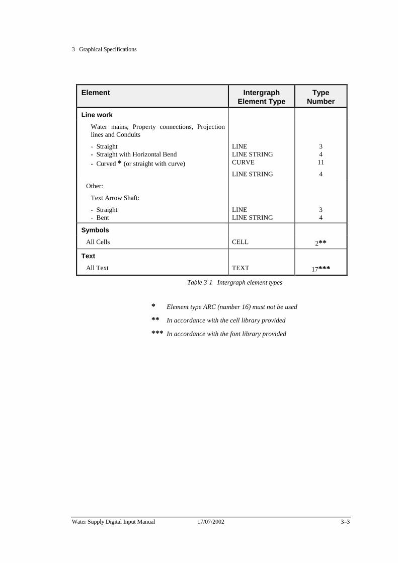
3 Graphical Specifications
Water Supply Digital Input Manual 17/07/2002 3–3
Element Intergraph
Element Type Type
Number
Line work
Water mains, Property connections, Projection lines and Conduits
- Straight - Straight with Horizontal Bend - Curved * (or straight with curve)
LINE LINE STRING CURVE
LINE STRING
3 4
11
4
Other:
Text Arrow Shaft:
- Straight - Bent
LINE LINE STRING
3 4
Symbols
All Cells CELL 2**
Text
All Text TEXT 17***
Table 3-1 Intergraph element types
* Element type ARC (number 16) must not be used
** In accordance with the cell library provided
*** In accordance with the font library provided
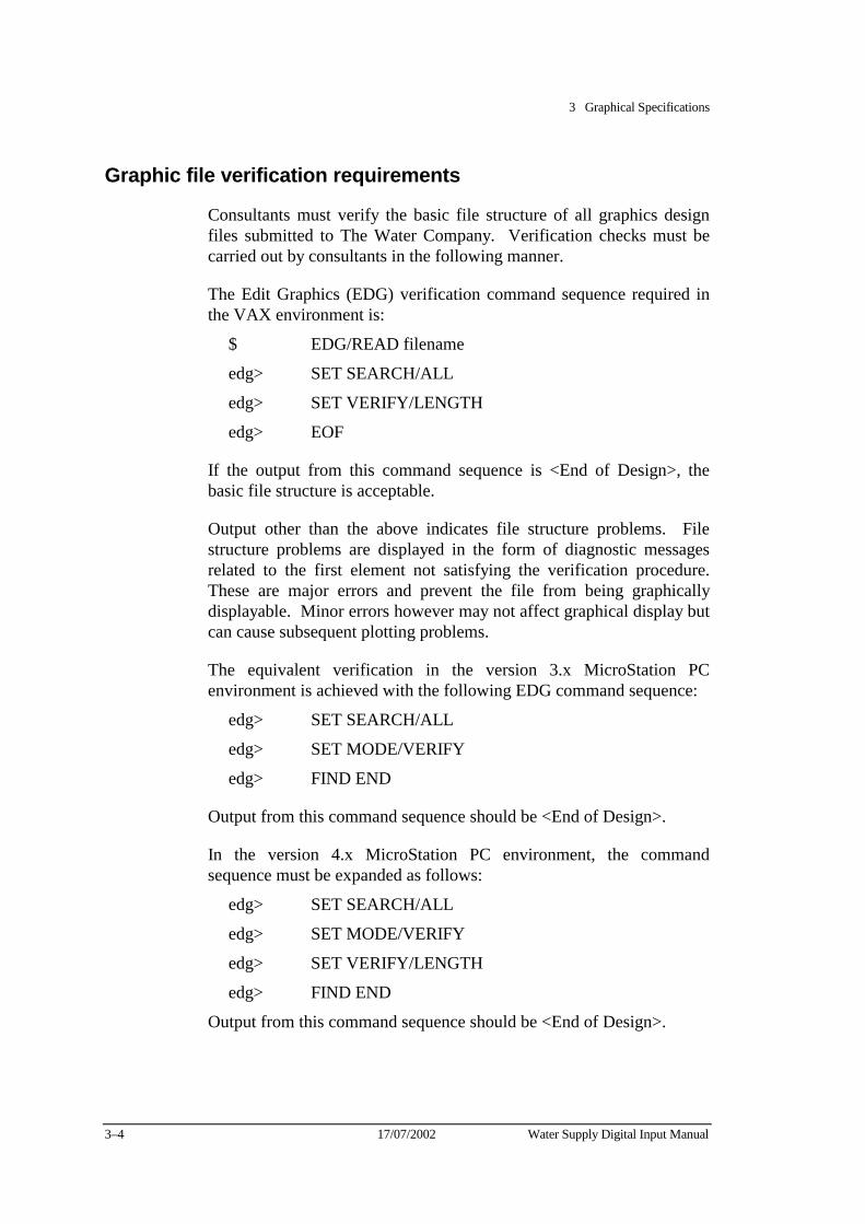
3 Graphical Specifications
3–4 17/07/2002 Water Supply Digital Input Manual
Graphic file verification requirements
Consultants must verify the basic file structure of all graphics design files submitted to The Water Company. Verification checks must be carried out by consultants in the following manner.
The Edit Graphics (EDG) verification command sequence required in the VAX environment is:
$ EDG/READ filename
edg> SET SEARCH/ALL
edg> SET VERIFY/LENGTH
edg> EOF
If the output from this command sequence is <End of Design>, the basic file structure is acceptable.
Output other than the above indicates file structure problems. File structure problems are displayed in the form of diagnostic messages related to the first element not satisfying the verification procedure. These are major errors and prevent the file from being graphically displayable. Minor errors however may not affect graphical display but can cause subsequent plotting problems.
The equivalent verification in the version 3.x MicroStation PC environment is achieved with the following EDG command sequence:
edg> SET SEARCH/ALL
edg> SET MODE/VERIFY
edg> FIND END
Output from this command sequence should be <End of Design>.
In the version 4.x MicroStation PC environment, the command sequence must be expanded as follows:
edg> SET SEARCH/ALL
edg> SET MODE/VERIFY
edg> SET VERIFY/LENGTH
edg> FIND END
Output from this command sequence should be <End of Design>.
3 Graphical Specifications
Water Supply Digital Input Manual 17/07/2002 3–5
Level structure Table 3-2 is the level structure assigned to water supply file elements related to as constructed information.
All miscellaneous items and notation other than those specified in this table, must be placed on the level of the feature to which they are related.
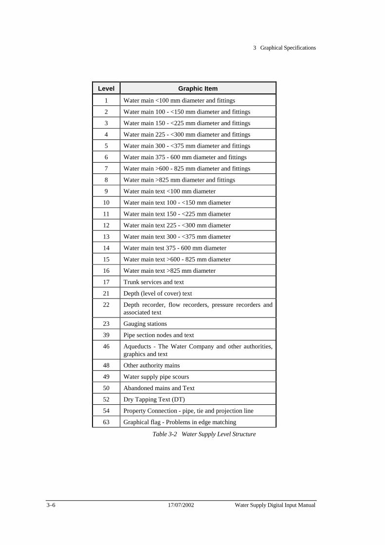
3 Graphical Specifications
3–6 17/07/2002 Water Supply Digital Input Manual
Level Graphic Item
1 Water main <100 mm diameter and fittings
2 Water main 100 - <150 mm diameter and fittings
3 Water main 150 - <225 mm diameter and fittings
4 Water main 225 - <300 mm diameter and fittings
5 Water main 300 - <375 mm diameter and fittings
6 Water main 375 - 600 mm diameter and fittings
7 Water main >600 - 825 mm diameter and fittings
8 Water main >825 mm diameter and fittings
9 Water main text <100 mm diameter
10 Water main text 100 - <150 mm diameter
11 Water main text 150 - <225 mm diameter
12 Water main text 225 - <300 mm diameter
13 Water main text 300 - <375 mm diameter
14 Water main test 375 - 600 mm diameter
15 Water main text >600 - 825 mm diameter
16 Water main text >825 mm diameter
17 Trunk services and text
21 Depth (level of cover) text
22 Depth recorder, flow recorders, pressure recorders and associated text
23 Gauging stations
39 Pipe section nodes and text
46 Aqueducts - The Water Company and other authorities, graphics and text
48 Other authority mains
49 Water supply pipe scours
50 Abandoned mains and Text
52 Dry Tapping Text (DT)
54 Property Connection - pipe, tie and projection line
63 Graphical flag - Problems in edge matching
Table 3-2 Water Supply Level Structure
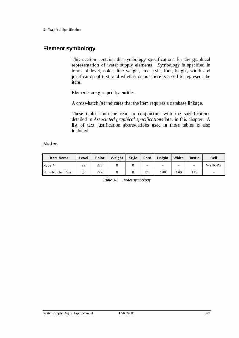
3 Graphical Specifications
Water Supply Digital Input Manual 17/07/2002 3–7
Element symbology
This section contains the symbology specifications for the graphical representation of water supply elements. Symbology is specified in terms of level, color, line weight, line style, font, height, width and justification of text, and whether or not there is a cell to represent the item.
Elements are grouped by entities.
A cross-hatch (#) indicates that the item requires a database linkage.
These tables must be read in conjunction with the specifications detailed in Associated graphical specifications later in this chapter. A list of text justification abbreviations used in these tables is also included.
Nodes
Item Name Level Color Weight Style Font Height Width Just’n Cell
Node
# 39 222 0 0 − − − − WSNODE
Node Number Text 39 222 0 0 31 3.00 3.00 LB −
Table 3-3 Nodes symbology
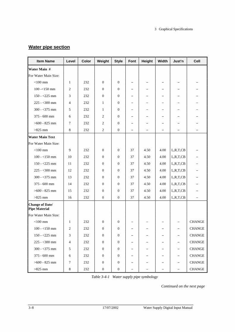
3 Graphical Specifications
3–8 17/07/2002 Water Supply Digital Input Manual
Water pipe section
Item Name Level Color Weight Style Font Height Width Just’n Cell
Water Main #
For Water Main Size:
<100 mm 1 232 0 0 − − − − −
100 -<150 mm 2 232 0 0 − − − − −
150 - <225 mm 3 232 0 0 − − − − −
225 - <300 mm 4 232 1 0 − − − − −
300 - <375 mm 5 232 1 0 − − − − −
375 - 600 mm 6 232 2 0 − − − − −
>600 - 825 mm 7 232 2 0 − − − − −
>825 mm 8 232 2 0 − − − − −
Water Main Text
For Water Main Size:
<100 mm 9 232 0 0 37 4.50 4.00 L,R,T,CB −
100 - <150 mm 10 232 0 0 37 4.50 4.00 L,R,T,CB −
150 - <225 mm 11 232 0 0 37 4.50 4.00 L,R,T,CB −
225 - <300 mm 12 232 0 0 37 4.50 4.00 L,R,T,CB −
300 - <375 mm 13 232 0 0 37 4.50 4.00 L,R,T,CB −
375 - 600 mm 14 232 0 0 37 4.50 4.00 L,R,T,CB −
>600 - 825 mm 15 232 0 0 37 4.50 4.00 L,R,T,CB −
>825 mm 16 232 0 0 37 4.50 4.00 L,R,T,CB −
Change of Date/ Pipe Material
For Water Main Size:
<100 mm 1 232 0 0 − − − − CHANGE
100 - <150 mm 2 232 0 0 − − − − CHANGE
150 - <225 mm 3 232 0 0 − − − − CHANGE
225 - <300 mm 4 232 0 0 − − − − CHANGE
300 - <375 mm 5 232 0 0 − − − − CHANGE
375 - 600 mm 6 232 0 0 − − − − CHANGE
>600 - 825 mm 7 232 0 0 − − − − CHANGE
>825 mm 8 232 0 0 − − − − CHANGE
Table 3-4-1 Water supply pipe symbology
Continued on the next page
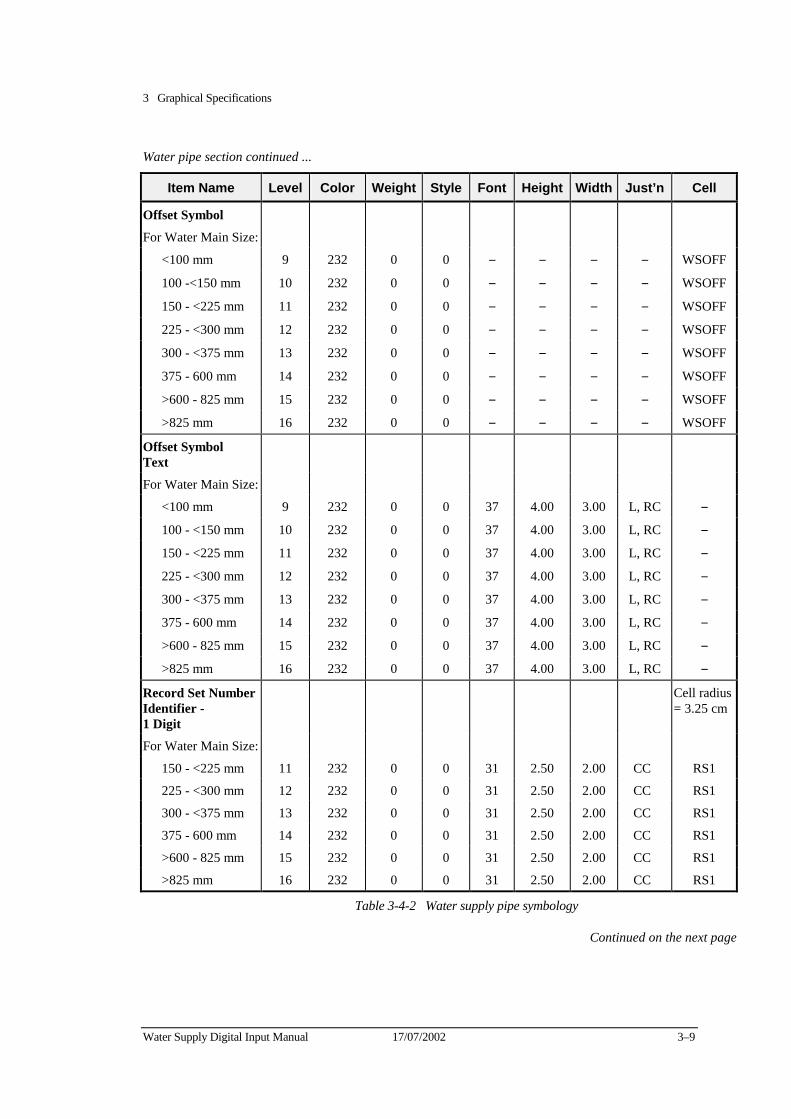
3 Graphical Specifications
Water Supply Digital Input Manual 17/07/2002 3–9
Water pipe section continued ...
Item Name Level Color Weight Style Font Height Width Just’n Cell
Offset Symbol
For Water Main Size:
<100 mm 9 232 0 0 − − − − WSOFF
100 -<150 mm 10 232 0 0 − − − − WSOFF
150 - <225 mm 11 232 0 0 − − − − WSOFF
225 - <300 mm 12 232 0 0 − − − − WSOFF
300 - <375 mm 13 232 0 0 − − − − WSOFF
375 - 600 mm 14 232 0 0 − − − − WSOFF
>600 - 825 mm 15 232 0 0 − − − − WSOFF
>825 mm 16 232 0 0 − − − − WSOFF
Offset Symbol Text
For Water Main Size:
<100 mm 9 232 0 0 37 4.00 3.00 L, RC −
100 - <150 mm 10 232 0 0 37 4.00 3.00 L, RC −
150 - <225 mm 11 232 0 0 37 4.00 3.00 L, RC −
225 - <300 mm 12 232 0 0 37 4.00 3.00 L, RC −
300 - <375 mm 13 232 0 0 37 4.00 3.00 L, RC −
375 - 600 mm 14 232 0 0 37 4.00 3.00 L, RC −
>600 - 825 mm 15 232 0 0 37 4.00 3.00 L, RC −
>825 mm 16 232 0 0 37 4.00 3.00 L, RC −
Record Set Number Identifier - 1 Digit
Cell radius= 3.25 cm
For Water Main Size:
150 - <225 mm 11 232 0 0 31 2.50 2.00 CC RS1
225 - <300 mm 12 232 0 0 31 2.50 2.00 CC RS1
300 - <375 mm 13 232 0 0 31 2.50 2.00 CC RS1
375 - 600 mm 14 232 0 0 31 2.50 2.00 CC RS1
>600 - 825 mm 15 232 0 0 31 2.50 2.00 CC RS1
>825 mm 16 232 0 0 31 2.50 2.00 CC RS1
Table 3-4-2 Water supply pipe symbology
Continued on the next page
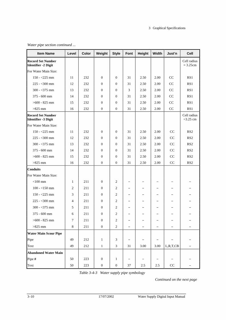
3 Graphical Specifications
3–10 17/07/2002 Water Supply Digital Input Manual
Water pipe section continued ...
Item Name Level Color Weight Style Font Height Width Just’n Cell
Record Set Number Identifier -2 Digit
Cell radius= 3.25cm
For Water Main Size:
150 - <225 mm 11 232 0 0 31 2.50 2.00 CC RS1
225 - <300 mm 12 232 0 0 31 2.50 2.00 CC RS1
300 - <375 mm 13 232 0 0 3 2.50 2.00 CC RS1
375 - 600 mm 14 232 0 0 31 2.50 2.00 CC RS1
>600 - 825 mm 15 232 0 0 31 2.50 2.00 CC RS1
>825 mm 16 232 0 0 31 2.50 2.00 CC RS1
Record Set Number Identifier -3 Digit
Cell radius=3.25 cm
For Water Main Size:
150 - <225 mm 11 232 0 0 31 2.50 2.00 CC RS2
225 - <300 mm 12 232 0 0 31 2.50 2.00 CC RS2
300 - <375 mm 13 232 0 0 31 2.50 2.00 CC RS2
375 - 600 mm 14 232 0 0 31 2.50 2.00 CC RS2
>600 - 825 mm 15 232 0 0 31 2.50 2.00 CC RS2
>825 mm 16 232 0 0 31 2.50 2.00 CC RS2
Conduits
For Water Main Size:
<100 mm 1 211 0 2 − − − − −
100 - <150 mm 2 211 0 2 − − − − −
150 - <225 mm 3 211 0 2 − − − − −
225 - <300 mm 4 211 0 2 − − − − −
300 - <375 mm 5 211 0 2 − − − − −
375 - 600 mm 6 211 0 2 − − − − −
>600 - 825 mm 7 211 0 2 − − − − −
>825 mm 8 211 0 2 − − − − −
Water Main Scour Pipe
Pipe 49 212 1 3 − − − − −
Text 49 212 1 3 31 3.00 3.00 L,R,T,CB −
Abandoned Water Main
Pipe # 50 223 0 1 − − − − −
Text 50 223 0 0 37 2.5 2.5 CC −
Table 3-4-3 Water supply pipe symbology
Continued on the next page
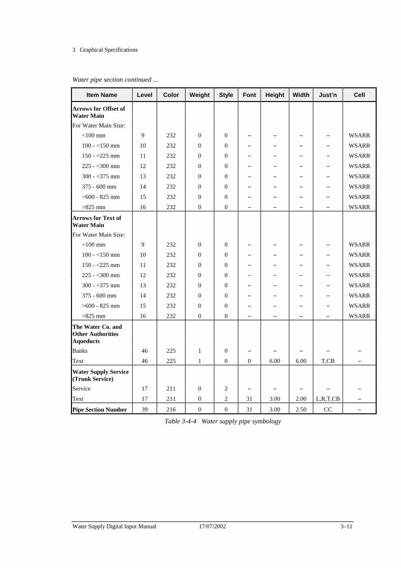
3 Graphical Specifications
Water Supply Digital Input Manual 17/07/2002 3–11
Water pipe section continued ...
Item Name Level Color Weight Style Font Height Width Just’n Cell
Arrows for Offset of Water Main
For Water Main Size: <100 mm 9 232 0 0 − − − − WSARR
100 - <150 mm 10 232 0 0 − − − − WSARR
150 - <225 mm 11 232 0 0 − − − − WSARR
225 - <300 mm 12 232 0 0 − − − − WSARR
300 - <375 mm 13 232 0 0 − − − − WSARR
375 - 600 mm 14 232 0 0 − − − − WSARR
>600 - 825 mm 15 232 0 0 − − − − WSARR
>825 mm 16 232 0 0 − − − − WSARR
Arrows for Text of Water Main
For Water Main Size: <100 mm 9 232 0 0 − − − − WSARR
100 - <150 mm 10 232 0 0 − − − − WSARR
150 - <225 mm 11 232 0 0 − − − − WSARR
225 - <300 mm 12 232 0 0 − − − − WSARR
300 - <375 mm 13 232 0 0 − − − − WSARR
375 - 600 mm 14 232 0 0 − − − − WSARR
>600 - 825 mm 15 232 0 0 − − − − WSARR
>825 mm 16 232 0 0 − − − − WSARR
The Water Co. and Other Authorities Aqueducts
Banks 46 225 1 0 − − − − − Text 46 225 1 0 0 6.00 6.00 T,CB −
Water Supply Service (Trunk Service)
Service 17 211 0 2 − − − − − Text 17 211 0 2 31 3.00 2.00 L,R,T,CB −
Pipe Section Number 39 216 0 0 31 3.00 2.50 CC −
Table 3-4-4 Water supply pipe symbology
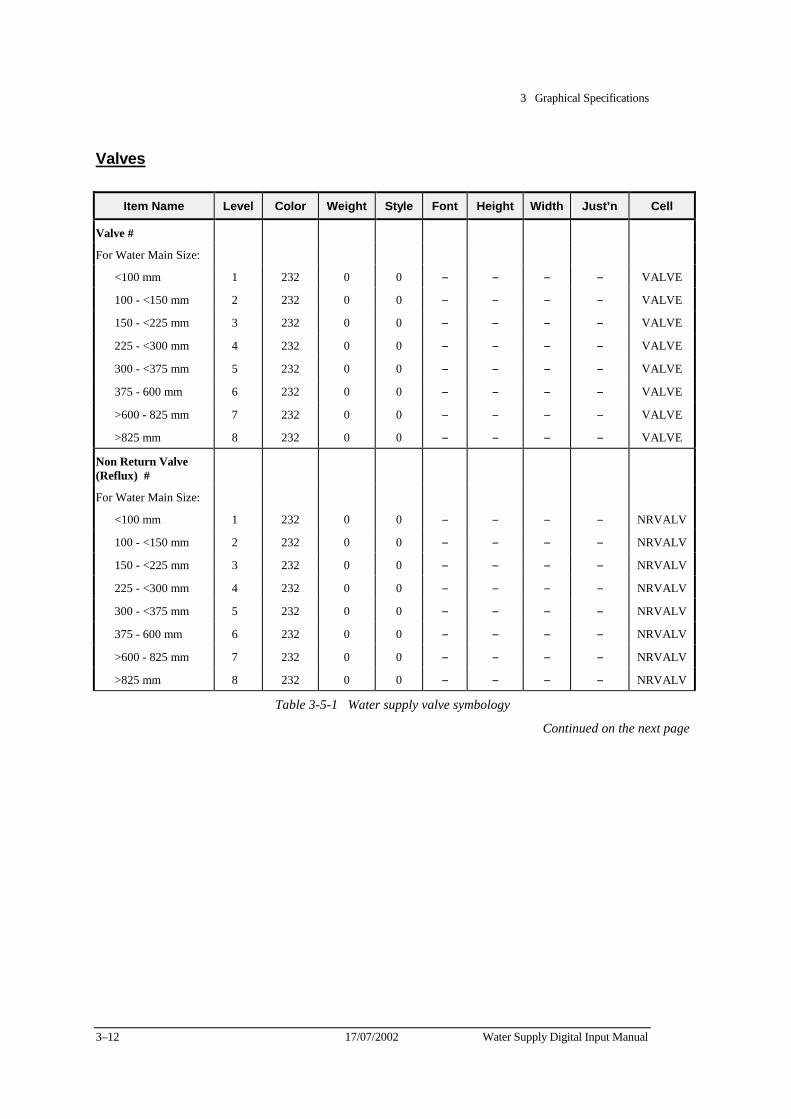
3 Graphical Specifications
3–12 17/07/2002 Water Supply Digital Input Manual
Valves
Item Name Level Color Weight Style Font Height Width Just’n Cell
Valve #
For Water Main Size:
<100 mm 1 232 0 0 − − − − VALVE
100 - <150 mm 2 232 0 0 − − − − VALVE
150 - <225 mm 3 232 0 0 − − − − VALVE
225 - <300 mm 4 232 0 0 − − − − VALVE
300 - <375 mm 5 232 0 0 − − − − VALVE
375 - 600 mm 6 232 0 0 − − − − VALVE
>600 - 825 mm 7 232 0 0 − − − − VALVE
>825 mm 8 232 0 0 − − − − VALVE
Non Return Valve (Reflux)
#
For Water Main Size:
<100 mm 1 232 0 0 − − − − NRVALV
100 - <150 mm 2 232 0 0 − − − − NRVALV
150 - <225 mm 3 232 0 0 − − − − NRVALV
225 - <300 mm 4 232 0 0 − − − − NRVALV
300 - <375 mm 5 232 0 0 − − − − NRVALV
375 - 600 mm 6 232 0 0 − − − − NRVALV
>600 - 825 mm 7 232 0 0 − − − − NRVALV
>825 mm 8 232 0 0 − − − − NRVALV
Table 3-5-1 Water supply valve symbology
Continued on the next page
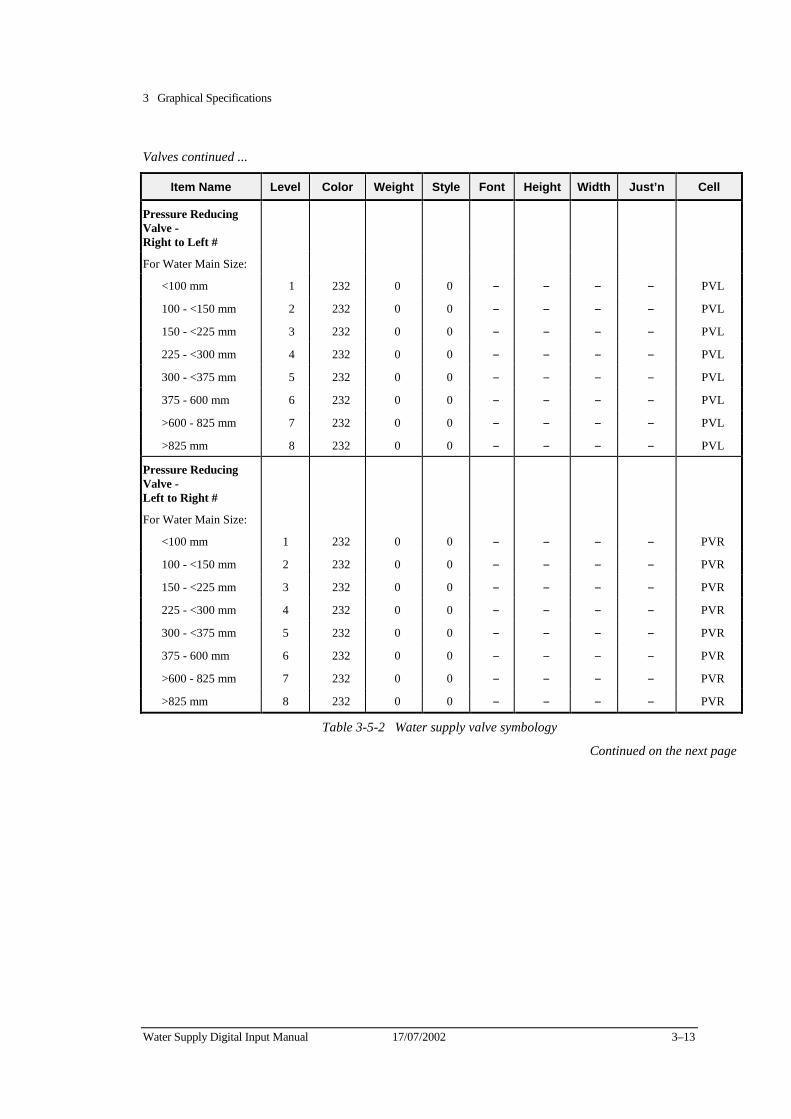
3 Graphical Specifications
Water Supply Digital Input Manual 17/07/2002 3–13
Valves continued ...
Item Name Level Color Weight Style Font Height Width Just’n Cell
Pressure Reducing Valve - Right to Left
#
For Water Main Size:
<100 mm 1 232 0 0 − − − − PVL
100 - <150 mm 2 232 0 0 − − − − PVL
150 - <225 mm 3 232 0 0 − − − − PVL
225 - <300 mm 4 232 0 0 − − − − PVL
300 - <375 mm 5 232 0 0 − − − − PVL
375 - 600 mm 6 232 0 0 − − − − PVL
>600 - 825 mm 7 232 0 0 − − − − PVL
>825 mm 8 232 0 0 − − − − PVL
Pressure Reducing Valve - Left to Right
#
For Water Main Size:
<100 mm 1 232 0 0 − − − − PVR
100 - <150 mm 2 232 0 0 − − − − PVR
150 - <225 mm 3 232 0 0 − − − − PVR
225 - <300 mm 4 232 0 0 − − − − PVR
300 - <375 mm 5 232 0 0 − − − − PVR
375 - 600 mm 6 232 0 0 − − − − PVR
>600 - 825 mm 7 232 0 0 − − − − PVR
>825 mm 8 232 0 0 − − − − PVR
Table 3-5-2 Water supply valve symbology
Continued on the next page
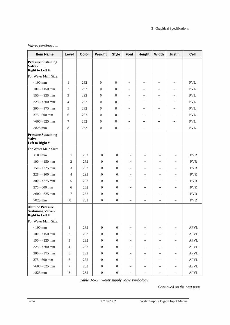
3 Graphical Specifications
3–14 17/07/2002 Water Supply Digital Input Manual
Valves continued ...
Item Name Level Color Weight Style Font Height Width Just’n Cell
Pressure Sustaining Valve - Right to Left
#
For Water Main Size:
<100 mm 1 232 0 0 − − − − PVL
100 - <150 mm 2 232 0 0 − − − − PVL
150 - <225 mm 3 232 0 0 − − − − PVL
225 - <300 mm 4 232 0 0 − − − − PVL
300 - <375 mm 5 232 0 0 − − − − PVL
375 - 600 mm 6 232 0 0 − − − − PVL
>600 - 825 mm 7 232 0 0 − − − − PVL
>825 mm 8 232 0 0 − − − − PVL
Pressure Sustaining Valve - Left to Right
#
For Water Main Size:
<100 mm 1 232 0 0 − − − − PVR
100 - <150 mm 2 232 0 0 − − − − PVR
150 - <225 mm 3 232 0 0 − − − − PVR
225 - <300 mm 4 232 0 0 − − − − PVR
300 - <375 mm 5 232 0 0 − − − − PVR
375 - 600 mm 6 232 0 0 − − − − PVR
>600 - 825 mm 7 232 0 0 − − − − PVR
>825 mm 8 232 0 0 − − − − PVR
Altitude Pressure Sustaining Valve - Right to Left
#
For Water Main Size:
<100 mm 1 232 0 0 − − − − APVL
100 - <150 mm 2 232 0 0 − − − − APVL
150 - <225 mm 3 232 0 0 − − − − APVL
225 - <300 mm 4 232 0 0 − − − − APVL
300 - <375 mm 5 232 0 0 − − − − APVL
375 - 600 mm 6 232 0 0 − − − − APVL
>600 - 825 mm 7 232 0 0 − − − − APVL
>825 mm 8 232 0 0 − − − − APVL
Table 3-5-3 Water supply valve symbology
Continued on the next page
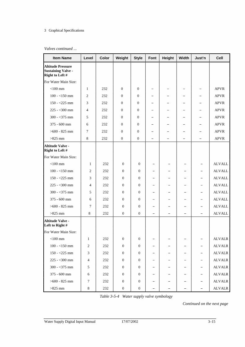
3 Graphical Specifications
Water Supply Digital Input Manual 17/07/2002 3–15
Valves continued ...
Item Name Level Color Weight Style Font Height Width Just’n Cell
Altitude Pressure Sustaining Valve - Right to Left
#
For Water Main Size:
<100 mm 1 232 0 0 − − − − APVR
100 - <150 mm 2 232 0 0 − − − − APVR
150 - <225 mm 3 232 0 0 − − − − APVR
225 - <300 mm 4 232 0 0 − − − − APVR
300 - <375 mm 5 232 0 0 − − − − APVR
375 - 600 mm 6 232 0 0 − − − − APVR
>600 - 825 mm 7 232 0 0 − − − − APVR
>825 mm 8 232 0 0 − − − − APVR
Altitude Valve - Right to Left
#
For Water Main Size:
<100 mm 1 232 0 0 − − − − ALVALL
100 - <150 mm 2 232 0 0 − − − − ALVALL
150 - <225 mm 3 232 0 0 − − − − ALVALL
225 - <300 mm 4 232 0 0 − − − − ALVALL
300 - <375 mm 5 232 0 0 − − − − ALVALL
375 - 600 mm 6 232 0 0 − − − − ALVALL
>600 - 825 mm 7 232 0 0 − − − − ALVALL
>825 mm 8 232 0 0 − − − − ALVALL
Altitude Valve - Left to Right
#
For Water Main Size:
<100 mm 1 232 0 0 − − − − ALVALR
100 - <150 mm 2 232 0 0 − − − − ALVALR
150 - <225 mm 3 232 0 0 − − − − ALVALR
225 - <300 mm 4 232 0 0 − − − − ALVALR
300 - <375 mm 5 232 0 0 − − − − ALVALR
375 - 600 mm 6 232 0 0 − − − − ALVALR
>600 - 825 mm 7 232 0 0 − − − − ALVALR
>825 mm 8 232 0 0 − − − − ALVALR
Table 3-5-4 Water supply valve symbology
Continued on the next page
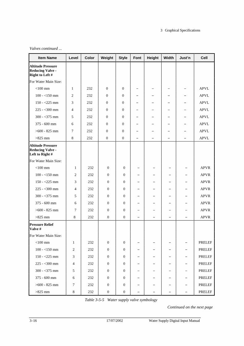
3 Graphical Specifications
3–16 17/07/2002 Water Supply Digital Input Manual
Valves continued ...
Item Name Level Color Weight Style Font Height Width Just’n Cell
Altitude Pressure Reducing Valve - Right to Left
#
For Water Main Size:
<100 mm 1 232 0 0 − − − − APVL
100 - <150 mm 2 232 0 0 − − − − APVL
150 - <225 mm 3 232 0 0 − − − − APVL
225 - <300 mm 4 232 0 0 − − − − APVL
300 - <375 mm 5 232 0 0 − − − − APVL
375 - 600 mm 6 232 0 0 − − − − APVL
>600 - 825 mm 7 232 0 0 − − − − APVL
>825 mm 8 232 0 0 − − − − APVL
Altitude Pressure Reducing Valve - Left to Right
#
For Water Main Size:
<100 mm 1 232 0 0 − − − − APVR
100 - <150 mm 2 232 0 0 − − − − APVR
150 - <225 mm 3 232 0 0 − − − − APVR
225 - <300 mm 4 232 0 0 − − − − APVR
300 - <375 mm 5 232 0 0 − − − − APVR
375 - 600 mm 6 232 0 0 − − − − APVR
>600 - 825 mm 7 232 0 0 − − − − APVR
>825 mm 8 232 0 0 − − − − APVR
Pressure Relief Valve
#
For Water Main Size:
<100 mm 1 232 0 0 − − − − PRELEF
100 - <150 mm 2 232 0 0 − − − − PRELEF
150 - <225 mm 3 232 0 0 − − − − PRELEF
225 - <300 mm 4 232 0 0 − − − − PRELEF
300 - <375 mm 5 232 0 0 − − − − PRELEF
375 - 600 mm 6 232 0 0 − − − − PRELEF
>600 - 825 mm 7 232 0 0 − − − − PRELEF
>825 mm 8 232 0 0 − − − − PRELEF
Table 3-5-5 Water supply valve symbology
Continued on the next page
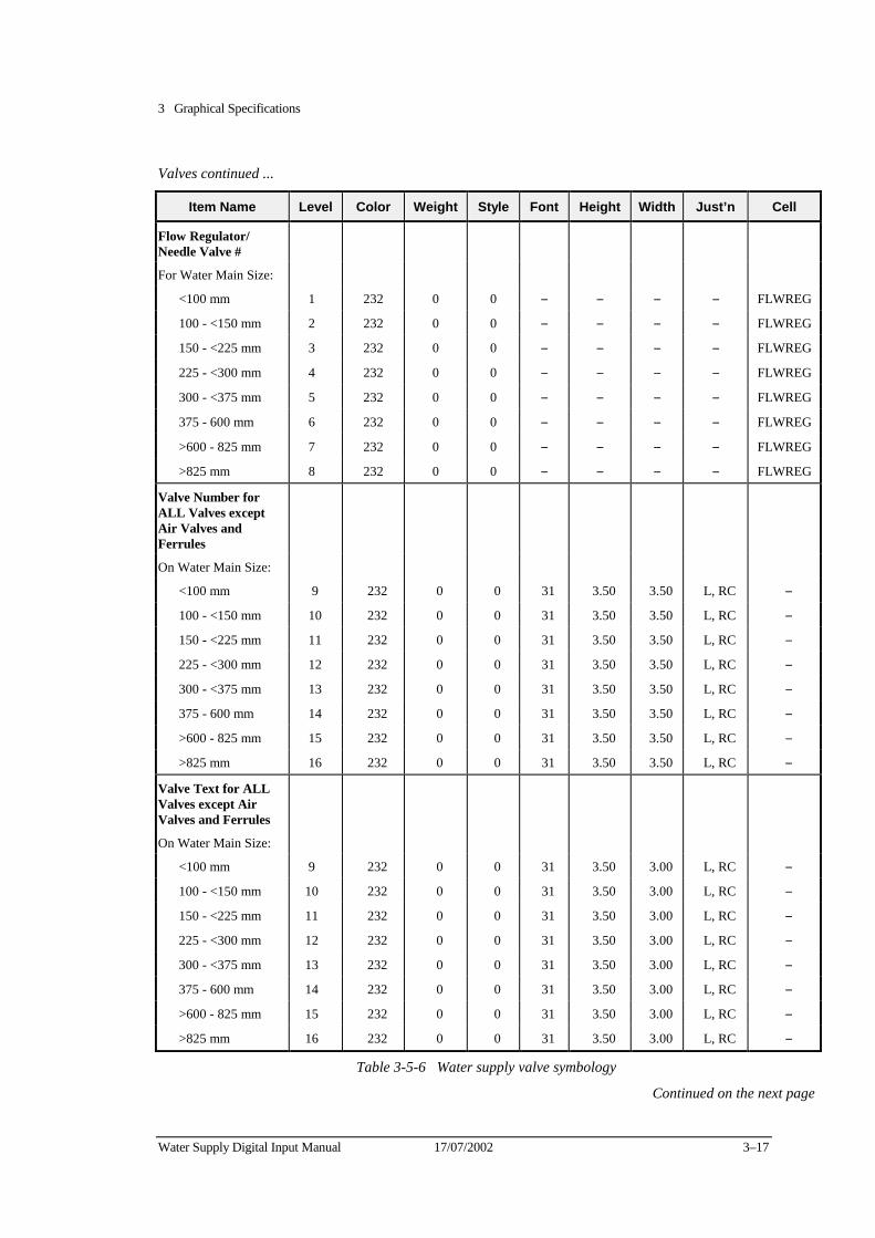
3 Graphical Specifications
Water Supply Digital Input Manual 17/07/2002 3–17
Valves continued ...
Item Name Level Color Weight Style Font Height Width Just’n Cell
Flow Regulator/ Needle Valve
#
For Water Main Size:
<100 mm 1 232 0 0 − − − − FLWREG
100 - <150 mm 2 232 0 0 − − − − FLWREG
150 - <225 mm 3 232 0 0 − − − − FLWREG
225 - <300 mm 4 232 0 0 − − − − FLWREG
300 - <375 mm 5 232 0 0 − − − − FLWREG
375 - 600 mm 6 232 0 0 − − − − FLWREG
>600 - 825 mm 7 232 0 0 − − − − FLWREG
>825 mm 8 232 0 0 − − − − FLWREG
Valve Number for ALL Valves except Air Valves and Ferrules
On Water Main Size:
<100 mm 9 232 0 0 31 3.50 3.50 L, RC −
100 - <150 mm 10 232 0 0 31 3.50 3.50 L, RC −
150 - <225 mm 11 232 0 0 31 3.50 3.50 L, RC −
225 - <300 mm 12 232 0 0 31 3.50 3.50 L, RC −
300 - <375 mm 13 232 0 0 31 3.50 3.50 L, RC −
375 - 600 mm 14 232 0 0 31 3.50 3.50 L, RC −
>600 - 825 mm 15 232 0 0 31 3.50 3.50 L, RC −
>825 mm 16 232 0 0 31 3.50 3.50 L, RC −
Valve Text for ALL Valves except Air Valves and Ferrules
On Water Main Size:
<100 mm 9 232 0 0 31 3.50 3.00 L, RC −
100 - <150 mm 10 232 0 0 31 3.50 3.00 L, RC −
150 - <225 mm 11 232 0 0 31 3.50 3.00 L, RC −
225 - <300 mm 12 232 0 0 31 3.50 3.00 L, RC −
300 - <375 mm 13 232 0 0 31 3.50 3.00 L, RC −
375 - 600 mm 14 232 0 0 31 3.50 3.00 L, RC −
>600 - 825 mm 15 232 0 0 31 3.50 3.00 L, RC −
>825 mm 16 232 0 0 31 3.50 3.00 L, RC −
Table 3-5-6 Water supply valve symbology
Continued on the next page

3 Graphical Specifications
3–18 17/07/2002 Water Supply Digital Input Manual
Valves continued ...
Item Name Level Color Weight Style Font Height Width Just’n Cell
Air Valve #
For Water Main Size:
<100 mm 1 210 0 0 − − − − AVTYPB
100 - <150 mm 2 210 0 0 − − − − AVTYPB
150 - <225 mm 3 210 0 0 − − − − AVTYPB
225 - <300 mm 4 210 0 0 − − − − AVTYPB
300 - <375 mm 5 210 0 0 − − − − AVTYPB
375 - 600 mm 6 210 0 0 − − − − AVTYPB
>600 - 825 mm 7 210 0 0 − − − − AVTYPB
>825 mm 8 210 0 0 − − − − AVTYPB
Air Valves Numbers
On Water Main Size:
<100 mm 9 210 0 0 31 3.50 3.50 L, RC −
100 - <150 mm 10 210 0 0 31 3.50 3.50 L, RC −
150 - <225 mm 11 210 0 0 31 3.50 3.50 L, RC −
225 - <300 mm 12 210 0 0 31 3.50 3.50 L, RC −
300 - <375 mm 13 210 0 0 31 3.50 3.50 L, RC −
375 - 600 mm 14 210 0 0 31 3.50 3.50 L, RC −
>600 - 825 mm 15 210 0 0 31 3.50 3.50 L, RC −
>825 mm 16 210 0 0 31 3.50 3.50 L, RC −
Text for Air Valves
On Water Main Size:
<100 mm 9 210 0 0 31 3.50 3.00 L, RC −
100 - <150 mm 10 210 0 0 31 3.50 3.00 L, RC −
150 - <225 mm 11 210 0 0 31 3.50 3.00 L, RC −
225 - <300 mm 12 210 0 0 31 3.50 3.00 L, RC −
300 - <375 mm 13 210 0 0 31 3.50 3.00 L, RC −
375 - 600 mm 14 210 0 0 31 3.50 3.00 L, RC −
>600 - 825 mm 15 210 0 0 31 3.50 3.00 L, RC −
>825 mm 16 210 0 0 31 3.50 3.00 L, RC −
Ferrule
Ferrule # 1 212 0 0 − − − − FERRUL
Number 9 212 0 0 31 3.50 3.50 L, RC −
Text 9 212 0 0 31 3.50 3.00 L, RC −
Table 3-5-7 Water supply valve symbology
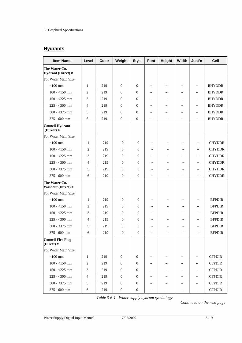
3 Graphical Specifications
Water Supply Digital Input Manual 17/07/2002 3–19
Hydrants
Item Name Level Color Weight Style Font Height Width Just’n Cell
The Water Co. Hydrant (Direct)
#
For Water Main Size:
<100 mm 1 219 0 0 − − − − BHYDDR
100 - <150 mm 2 219 0 0 − − − − BHYDDR
150 - <225 mm 3 219 0 0 − − − − BHYDDR
225 - <300 mm 4 219 0 0 − − − − BHYDDR
300 - <375 mm 5 219 0 0 − − − − BHYDDR
375 - 600 mm 6 219 0 0 − − − − BHYDDR
Council Hydrant (Direct)
#
For Water Main Size:
<100 mm 1 219 0 0 − − − − CHYDDR
100 - <150 mm 2 219 0 0 − − − − CHYDDR
150 - <225 mm 3 219 0 0 − − − − CHYDDR
225 - <300 mm 4 219 0 0 − − − − CHYDDR
300 - <375 mm 5 219 0 0 − − − − CHYDDR
375 - 600 mm 6 219 0 0 − − − − CHYDDR
The Water Co. Washout (Direct)
#
For Water Main Size:
<100 mm 1 219 0 0 − − − − BFPDIR
100 - <150 mm 2 219 0 0 − − − − BFPDIR
150 - <225 mm 3 219 0 0 − − − − BFPDIR
225 - <300 mm 4 219 0 0 − − − − BFPDIR
300 - <375 mm 5 219 0 0 − − − − BFPDIR
375 - 600 mm 6 219 0 0 − − − − BFPDIR
Council Fire Plug (Direct)
#
For Water Main Size:
<100 mm 1 219 0 0 − − − − CFPDIR
100 - <150 mm 2 219 0 0 − − − − CFPDIR
150 - <225 mm 3 219 0 0 − − − − CFPDIR
225 - <300 mm 4 219 0 0 − − − − CFPDIR
300 - <375 mm 5 219 0 0 − − − − CFPDIR
375 - 600 mm 6 219 0 0 − − − − CFPDIR
Table 3-6-1 Water supply hydrant symbology Continued on the next page
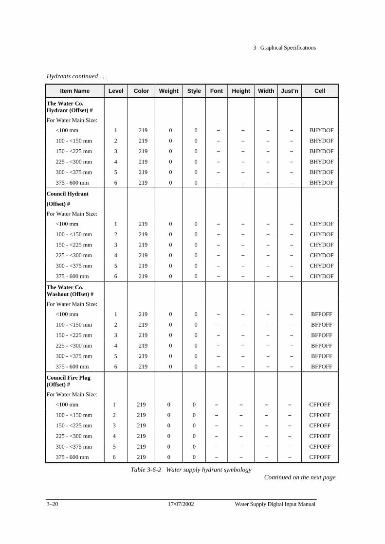
3 Graphical Specifications
3–20 17/07/2002 Water Supply Digital Input Manual
Hydrants continued . . .
Item Name Level Color Weight Style Font Height Width Just’n Cell
The Water Co. Hydrant (Offset)
#
For Water Main Size:
<100 mm 1 219 0 0 − − − − BHYDOF
100 - <150 mm 2 219 0 0 − − − − BHYDOF
150 - <225 mm 3 219 0 0 − − − − BHYDOF
225 - <300 mm 4 219 0 0 − − − − BHYDOF
300 - <375 mm 5 219 0 0 − − − − BHYDOF
375 - 600 mm 6 219 0 0 − − − − BHYDOF
Council Hydrant
(Offset) #
For Water Main Size:
<100 mm 1 219 0 0 − − − − CHYDOF
100 - <150 mm 2 219 0 0 − − − − CHYDOF
150 - <225 mm 3 219 0 0 − − − − CHYDOF
225 - <300 mm 4 219 0 0 − − − − CHYDOF
300 - <375 mm 5 219 0 0 − − − − CHYDOF
375 - 600 mm 6 219 0 0 − − − − CHYDOF
The Water Co. Washout (Offset)
#
For Water Main Size:
<100 mm 1 219 0 0 − − − − BFPOFF
100 - <150 mm 2 219 0 0 − − − − BFPOFF
150 - <225 mm 3 219 0 0 − − − − BFPOFF
225 - <300 mm 4 219 0 0 − − − − BFPOFF
300 - <375 mm 5 219 0 0 − − − − BFPOFF
375 - 600 mm 6 219 0 0 − − − − BFPOFF
Council Fire Plug (Offset)
#
For Water Main Size:
<100 mm 1 219 0 0 − − − − CFPOFF
100 - <150 mm 2 219 0 0 − − − − CFPOFF
150 - <225 mm 3 219 0 0 − − − − CFPOFF
225 - <300 mm 4 219 0 0 − − − − CFPOFF
300 - <375 mm 5 219 0 0 − − − − CFPOFF
375 - 600 mm 6 219 0 0 − − − − CFPOFF
Table 3-6-2 Water supply hydrant symbology Continued on the next page
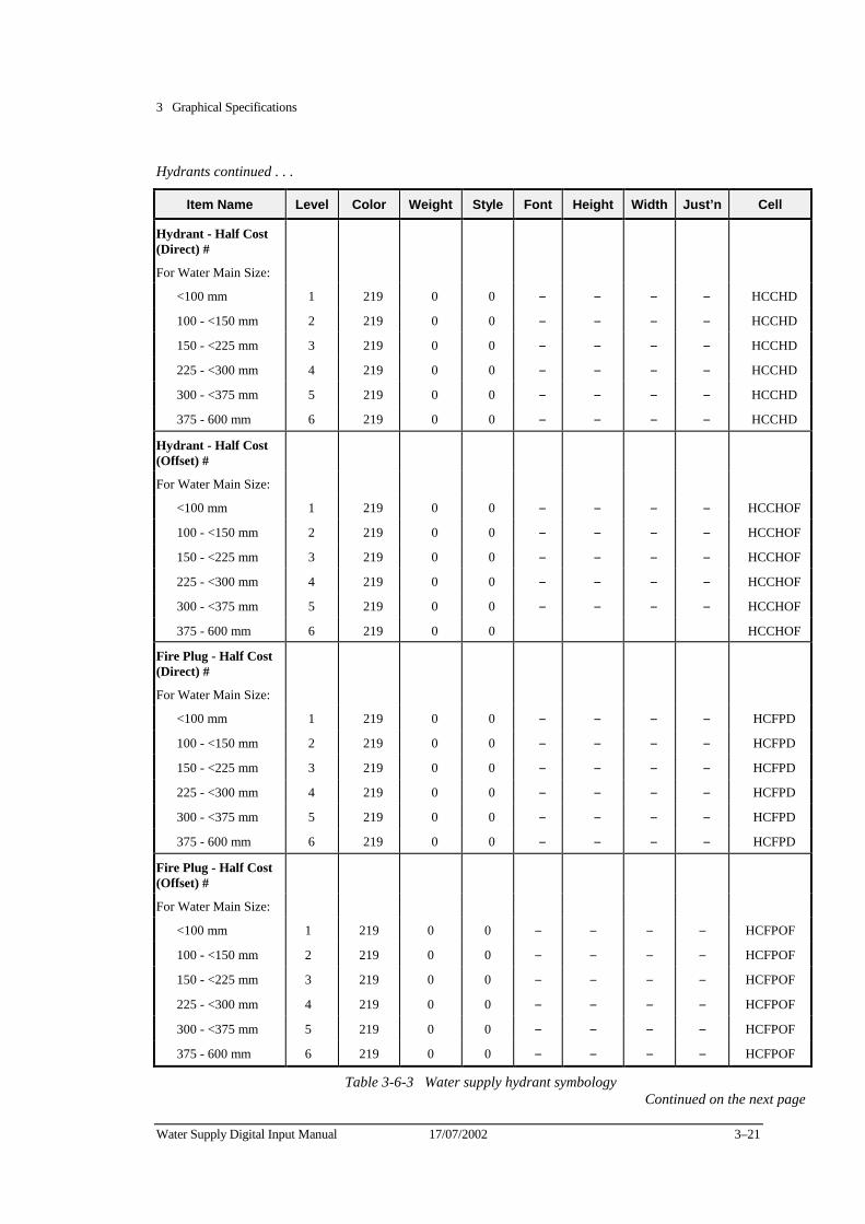
3 Graphical Specifications
Water Supply Digital Input Manual 17/07/2002 3–21
Hydrants continued . . .
Item Name Level Color Weight Style Font Height Width Just’n Cell
Hydrant - Half Cost (Direct)
#
For Water Main Size:
<100 mm 1 219 0 0 − − − − HCCHD
100 - <150 mm 2 219 0 0 − − − − HCCHD
150 - <225 mm 3 219 0 0 − − − − HCCHD
225 - <300 mm 4 219 0 0 − − − − HCCHD
300 - <375 mm 5 219 0 0 − − − − HCCHD
375 - 600 mm 6 219 0 0 − − − − HCCHD
Hydrant - Half Cost (Offset)
#
For Water Main Size:
<100 mm 1 219 0 0 − − − − HCCHOF
100 - <150 mm 2 219 0 0 − − − − HCCHOF
150 - <225 mm 3 219 0 0 − − − − HCCHOF
225 - <300 mm 4 219 0 0 − − − − HCCHOF
300 - <375 mm 5 219 0 0 − − − − HCCHOF
375 - 600 mm 6 219 0 0 HCCHOF
Fire Plug - Half Cost (Direct)
#
For Water Main Size:
<100 mm 1 219 0 0 − − − − HCFPD
100 - <150 mm 2 219 0 0 − − − − HCFPD
150 - <225 mm 3 219 0 0 − − − − HCFPD
225 - <300 mm 4 219 0 0 − − − − HCFPD
300 - <375 mm 5 219 0 0 − − − − HCFPD
375 - 600 mm 6 219 0 0 − − − − HCFPD
Fire Plug - Half Cost (Offset)
#
For Water Main Size:
<100 mm 1 219 0 0 − − − − HCFPOF
100 - <150 mm 2 219 0 0 − − − − HCFPOF
150 - <225 mm 3 219 0 0 − − − − HCFPOF
225 - <300 mm 4 219 0 0 − − − − HCFPOF
300 - <375 mm 5 219 0 0 − − − − HCFPOF
375 - 600 mm 6 219 0 0 − − − − HCFPOF
Table 3-6-3 Water supply hydrant symbology Continued on the next page
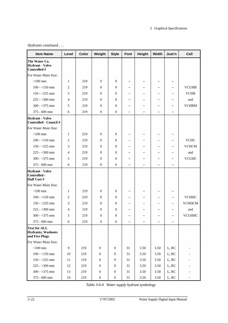
3 Graphical Specifications
3–22 17/07/2002 Water Supply Digital Input Manual
Hydrants continued . . .
Item Name Level Color Weight Style Font Height Width Just’n Cell
The Water Co. Hydrant - Valve Controlled
#
For Water Main Size:
<100 mm 1 219 0 0 − − − −
100 - <150 mm 2 219 0 0 − − − − VCUHB
150 - <225 mm 3 219 0 0 − − − − VCHB
225 - <300 mm 4 219 0 0 − − − − and
300 - <375 mm 5 219 0 0 − − − − VCHBM
375 - 600 mm 6 219 0 0 − − − −
Hydrant - Valve Controlled - Council
#
For Water Main Size:
<100 mm 1 219 0 0 − − − −
100 - <150 mm 2 219 0 0 − − − − VCHC
150 - <225 mm 3 219 0 0 − − − − VCHCM
225 - <300 mm 4 219 0 0 − − − − and
300 - <375 mm 5 219 0 0 − − − − VCUHC
375 - 600 mm 6 219 0 0 − − − −
Hydrant - Valve Controlled - Half Cost
#
For Water Main Size:
<100 mm 1 219 0 0 − − − −
100 - <150 mm 2 219 0 0 − − − − VCHHC
150 - <225 mm 3 219 0 0 − − − − VCHHCM
225 - <300 mm 4 219 0 0 − − − − and
300 - <375 mm 5 219 0 0 − − − − VCUHHC
375 - 600 mm 6 219 0 0 − − − −
Text for ALL Hydrants, Washouts and Fire Plugs
For Water Main Size:
<100 mm 9 219 0 0 31 3.50 3.50 L, RC -
100 - <150 mm 10 219 0 0 31 3.50 3.50 L, RC -
150 - <225 mm 11 219 0 0 31 3.50 3.50 L, RC -
225 - <300 mm 12 219 0 0 31 3.50 3.50 L, RC -
300 - <375 mm 13 219 0 0 31 3.50 3.50 L, RC -
375 - 600 mm 14 219 0 0 31 3.50 3.50 L, RC -
Table 3-6-4 Water supply hydrant symbology
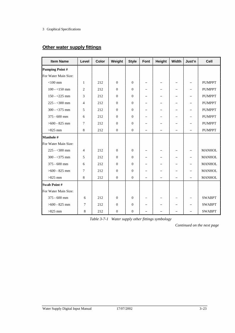
3 Graphical Specifications
Water Supply Digital Input Manual 17/07/2002 3–23
Other water supply fittings
Item Name Level Color Weight Style Font Height Width Just’n Cell
Pumping Point #
For Water Main Size:
<100 mm 1 212 0 0 − − − − PUMPPT
100 - <150 mm 2 212 0 0 − − − − PUMPPT
150 - <225 mm 3 212 0 0 − − − − PUMPPT
225 - <300 mm 4 212 0 0 − − − − PUMPPT
300 - <375 mm 5 212 0 0 − − − − PUMPPT
375 - 600 mm 6 212 0 0 − − − − PUMPPT
>600 - 825 mm 7 212 0 0 − − − − PUMPPT
>825 mm 8 212 0 0 − − − − PUMPPT
Manhole #
For Water Main Size:
225 - <300 mm 4 212 0 0 − − − − MANHOL
300 - <375 mm 5 212 0 0 − − − − MANHOL
375 - 600 mm 6 212 0 0 − − − − MANHOL
>600 - 825 mm 7 212 0 0 − − − − MANHOL
>825 mm 8 212 0 0 − − − − MANHOL
Swab Point #
For Water Main Size:
375 - 600 mm 6 212 0 0 − − − − SWABPT
>600 - 825 mm 7 212 0 0 − − − − SWABPT
>825 mm 8 212 0 0 − − − − SWABPT
Table 3-7-1 Water supply other fittings symbology Continued on the next page

3 Graphical Specifications
3–24 17/07/2002 Water Supply Digital Input Manual
Other water supply fittings continued ...
Item Name Level Color Weight Style Font Height Width Just’n Cell
Reducer/Taper #
For Water Main Size:
<100 mm 1 212 0 0 − − − − REDUCE
100 - <150 mm 2 212 0 0 − − − − REDUCE
150 - <225 mm 3 212 0 0 − − − − REDUCE
225 - <300 mm 4 212 0 0 − − − − REDUCE
300 - <375 mm 5 212 0 0 − − − − REDUCE
375 - 600 mm 6 212 0 0 − − − − REDUCE
>600 - 825 mm 7 212 0 0 − − − − REDUCE
>825 mm 8 212 0 0 − − − − REDUCE
Reducer/Taper Text
On Water Main Size:
<100 mm 9 212 0 0 31 3.50 3.50 L, RC −
100 - <150 mm 10 212 0 0 31 3.50 3.50 L, RC −
150 - <225 mm 11 212 0 0 31 3.50 3.50 L, RC −
225 - <300 mm 12 212 0 0 31 3.50 3.50 L, RC −
300 - <375 mm 13 212 0 0 31 3.50 3.50 L, RC −
375 - 600 mm 14 212 0 0 31 3.50 3.50 L, RC −
>600 - 825 mm 15 212 0 0 31 3.50 3.50 L, RC −
>825 mm 16 212 0 0 31 3.50 3.50 L, RC −
Blank End/Cap #
On Water Main Size:
<100 mm 1 212 0 0 − − − − BLNKED
100 - <150 mm 2 212 0 0 − − − − BLNKED
150 - <225 mm 3 212 0 0 − − − − BLNKED
225 - <300 mm 4 212 0 0 − − − − BLNKED
300 - <375 mm 5 212 0 0 − − − − BLNKED
375 - 600 mm 6 212 0 0 − − − − BLNKED
>600 - 825 mm 7 212 0 0 − − − − BLNKED
>825 mm 8 212 0 0 − − − − BLNKED
Table 3-7-2 Water supply other fittings symbology Continued on the next page
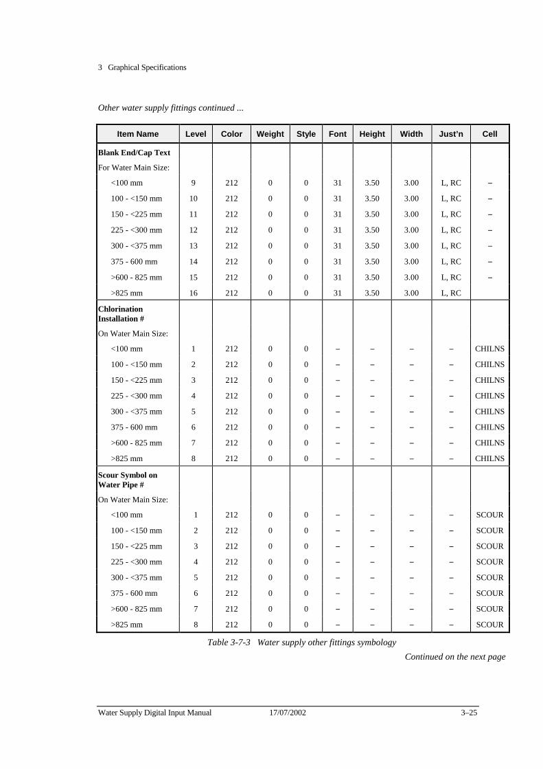
3 Graphical Specifications
Water Supply Digital Input Manual 17/07/2002 3–25
Other water supply fittings continued ...
Item Name Level Color Weight Style Font Height Width Just’n Cell
Blank End/Cap Text
For Water Main Size:
<100 mm 9 212 0 0 31 3.50 3.00 L, RC −
100 - <150 mm 10 212 0 0 31 3.50 3.00 L, RC −
150 - <225 mm 11 212 0 0 31 3.50 3.00 L, RC −
225 - <300 mm 12 212 0 0 31 3.50 3.00 L, RC −
300 - <375 mm 13 212 0 0 31 3.50 3.00 L, RC −
375 - 600 mm 14 212 0 0 31 3.50 3.00 L, RC −
>600 - 825 mm 15 212 0 0 31 3.50 3.00 L, RC −
>825 mm 16 212 0 0 31 3.50 3.00 L, RC
Chlorination Installation
#
On Water Main Size:
<100 mm 1 212 0 0 − − − − CHILNS
100 - <150 mm 2 212 0 0 − − − − CHILNS
150 - <225 mm 3 212 0 0 − − − − CHILNS
225 - <300 mm 4 212 0 0 − − − − CHILNS
300 - <375 mm 5 212 0 0 − − − − CHILNS
375 - 600 mm 6 212 0 0 − − − − CHILNS
>600 - 825 mm 7 212 0 0 − − − − CHILNS
>825 mm 8 212 0 0 − − − − CHILNS
Scour Symbol on Water Pipe
#
On Water Main Size:
<100 mm 1 212 0 0 − − − − SCOUR
100 - <150 mm 2 212 0 0 − − − − SCOUR
150 - <225 mm 3 212 0 0 − − − − SCOUR
225 - <300 mm 4 212 0 0 − − − − SCOUR
300 - <375 mm 5 212 0 0 − − − − SCOUR
375 - 600 mm 6 212 0 0 − − − − SCOUR
>600 - 825 mm 7 212 0 0 − − − − SCOUR
>825 mm 8 212 0 0 − − − − SCOUR
Table 3-7-3 Water supply other fittings symbology Continued on the next page
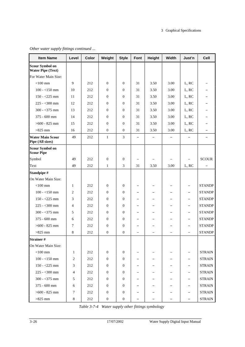
3 Graphical Specifications
3–26 17/07/2002 Water Supply Digital Input Manual
Other water supply fittings continued ...
Item Name Level Color Weight Style Font Height Width Just’n Cell
Scour Symbol on Water Pipe (Text)
For Water Main Size:
<100 mm 9 212 0 0 31 3.50 3.00 L, RC −
100 - <150 mm 10 212 0 0 31 3.50 3.00 L, RC −
150 - <225 mm 11 212 0 0 31 3.50 3.00 L, RC −
225 - <300 mm 12 212 0 0 31 3.50 3.00 L, RC −
300 - <375 mm 13 212 0 0 31 3.50 3.00 L, RC −
375 - 600 mm 14 212 0 0 31 3.50 3.00 L, RC −
>600 - 825 mm 15 212 0 0 31 3.50 3.00 L, RC −
>825 mm 16 212 0 0 31 3.50 3.00 L, RC −
Water Main Scour Pipe (All sizes)
49 212 1 3 − − − − −
Scour Symbol on Scour Pipe
Symbol 49 212 0 0 − − − − SCOUR
Text 49 212 1 3 31 3.50 3.00 L, RC −
Standpipe #
On Water Main Size:
<100 mm 1 212 0 0 − − − − STANDP
100 - <150 mm 2 212 0 0 − − − − STANDP
150 - <225 mm 3 212 0 0 − − − − STANDP
225 - <300 mm 4 212 0 0 − − − − STANDP
300 - <375 mm 5 212 0 0 − − − − STANDP
375 - 600 mm 6 212 0 0 − − − − STANDP
>600 - 825 mm 7 212 0 0 − − − − STANDP
>825 mm 8 212 0 0 − − − − STANDP
Strainer #
On Water Main Size:
<100 mm 1 212 0 0 − − − − STRAIN
100 - <150 mm 2 212 0 0 − − − − STRAIN
150 - <225 mm 3 212 0 0 − − − − STRAIN
225 - <300 mm 4 212 0 0 − − − − STRAIN
300 - <375 mm 5 212 0 0 − − − − STRAIN
375 - 600 mm 6 212 0 0 − − − − STRAIN
>600 - 825 mm 7 212 0 0 − − − − STRAIN
>825 mm 8 212 0 0 − − − − STRAIN
Table 3-7-4 Water supply other fittings symbology
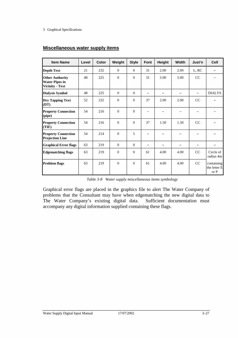
3 Graphical Specifications
Water Supply Digital Input Manual 17/07/2002 3–27
Miscellaneous water supply items
Item Name Level Color Weight Style Font Height Width Just’n Cell
Depth Text 21 232 0 0 31 2.00 2.00 L, RC −
Other Authority Water Pipes in Vicinity - Text
48 225 0 0 31 5.00 5.00 CC −
Dialysis Symbol 48 225 0 0 − − − − DIALYS
Dry Tapping Text (DT)
52 232 0 0 37 2.00 2.00 CC −
Property Connection (pipe)
54 216 0 0 − − − − −
Property Connection (TIE)
54 216 0 0 37 1.50 1.50 CC −
Property Connection Projection Line
54 214 0 5 − − − − −
Graphical Error flags 63 219 0 0 − − − − −
Edgematching flags 63 219 0 0 61 4.00 4.00 CC Circle of radius 4m
Problem flags 63 219 0 0 61 4.00 4.00 CC containing the letter E
or P
Table 3-8 Water supply miscellaneous items symbology
Graphical error flags are placed in the graphics file to alert The Water Company of problems that the Consultant may have when edgematching the new digital data to The Water Company’s existing digital data. Sufficient documentation must accompany any digital information supplied containing these flags.
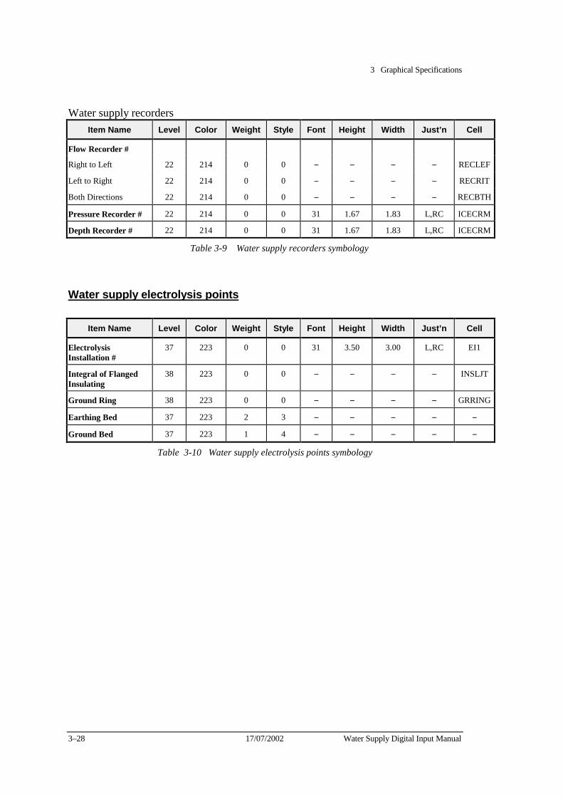
3 Graphical Specifications
3–28 17/07/2002 Water Supply Digital Input Manual
Water supply recorders Item Name Level Color Weight Style Font Height Width Just’n Cell
Flow Recorder #
Right to Left 22 214 0 0 − − − − RECLEF
Left to Right 22 214 0 0 − − − − RECRIT
Both Directions 22 214 0 0 − − − − RECBTH
Pressure Recorder # 22 214 0 0 31 1.67 1.83 L,RC ICECRM
Depth Recorder # 22 214 0 0 31 1.67 1.83 L,RC ICECRM
Table 3-9 Water supply recorders symbology
Water supply electrolysis points
Item Name Level Color Weight Style Font Height Width Just’n Cell
Electrolysis Installation
#
37 223 0 0 31 3.50 3.00 L,RC EI1
Integral of Flanged Insulating
38 223 0 0 − − − − INSLJT
Ground Ring 38 223 0 0 − − − − GRRING
Earthing Bed 37 223 2 3 − − − − −
Ground Bed 37 223 1 4 − − − − −
Table 3-10 Water supply electrolysis points symbology
3 Graphical Specifications
Water Supply Digital Input Manual 17/07/2002 3–29
Graphics Schedule 2 - For MicroStation in Unlinked .DGN format
This Schedule is the same as Schedule 1 with the exception the graphical elements must not have any elements with database links in sewerage file.
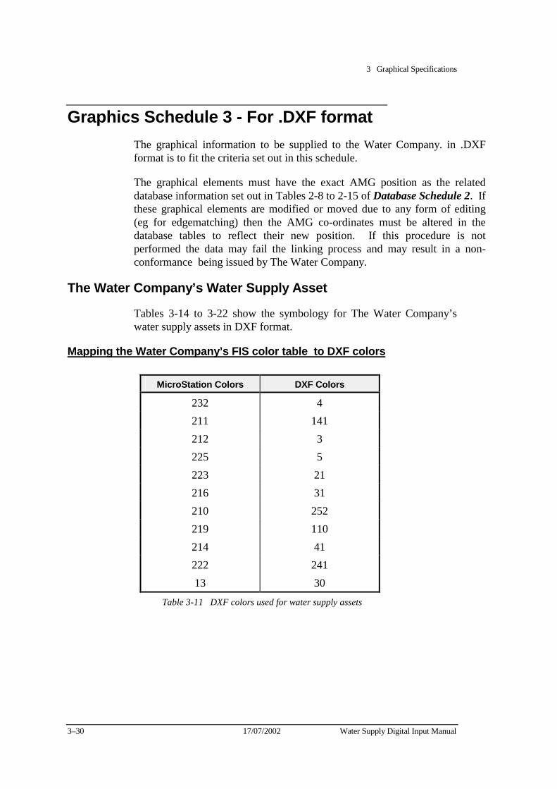
3 Graphical Specifications
3–30 17/07/2002 Water Supply Digital Input Manual
Graphics Schedule 3 - For .DXF format The graphical information to be supplied to the Water Company. in .DXF format is to fit the criteria set out in this schedule.
The graphical elements must have the exact AMG position as the related database information set out in Tables 2-8 to 2-15 of Database Schedule 2. If these graphical elements are modified or moved due to any form of editing (eg for edgematching) then the AMG co-ordinates must be altered in the database tables to reflect their new position. If this procedure is not performed the data may fail the linking process and may result in a non-conformance being issued by The Water Company.
The Water Company’s Water Supply Asset
Tables 3-14 to 3-22 show the symbology for The Water Company’s water supply assets in DXF format.
Mapping the Water Company’s FIS color table to DXF colors
MicroStation Colors DXF Colors
232 4 211 141 212 3 225 5 223 21 216 31 210 252 219 110 214 41 222 241 13 30
Table 3-11 DXF colors used for water supply assets
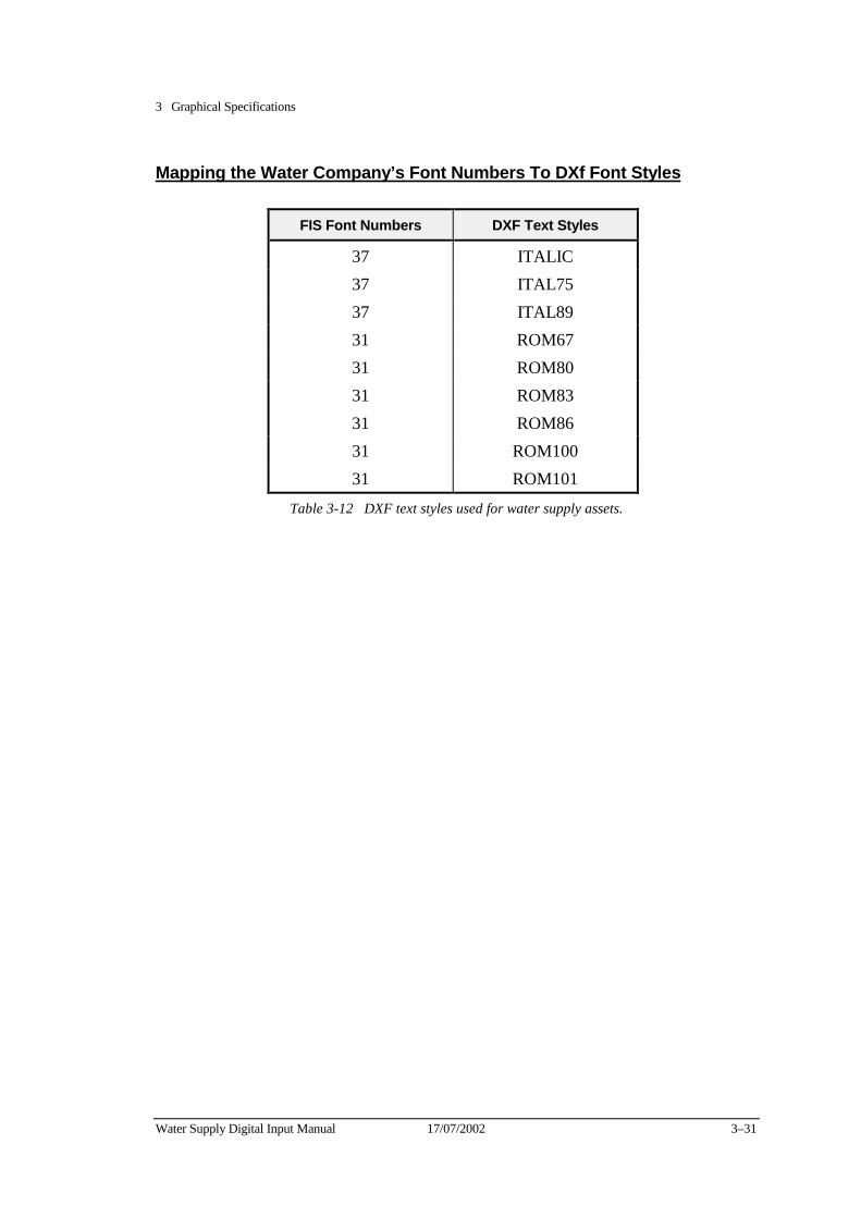
3 Graphical Specifications
Water Supply Digital Input Manual 17/07/2002 3–31
Mapping the Water Company’s Font Numbers To DXf Font Styles
FIS Font Numbers DXF Text Styles
37 ITALIC 37 ITAL75 37 ITAL89 31 ROM67 31 ROM80 31 ROM83 31 ROM86 31 ROM100 31 ROM101
Table 3-12 DXF text styles used for water supply assets.
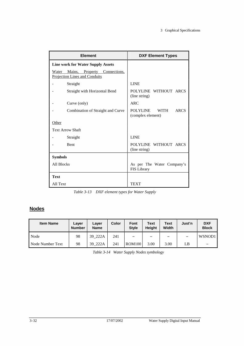
3 Graphical Specifications
3–32 17/07/2002 Water Supply Digital Input Manual
Element DXF Element Types
Line work for Water Supply Assets
Water Mains, Property Connections, Projection Lines and Conduits
- Straight LINE
- Straight with Horizontal Bend POLYLINE WITHOUT ARCS (line string)
- Curve (only) ARC
- Combination of Straight and Curve POLYLINE WITH ARCS (complex element)
Other
Text Arrow Shaft
- Straight LINE
- Bent POLYLINE WITHOUT ARCS (line string)
Symbols
All Blocks As per The Water Company’s FIS Library
Text
All Text TEXT
Table 3-13 DXF element types for Water Supply
Nodes
Item Name Layer Number
Layer Name
Color Font Style
Text Height
Text Width
Just’n DXF Block
Node 98 39_222A 241 − − − − WSNOD1
Node Number Text 98 39_222A 241 ROM100 3.00 3.00 LB −
Table 3-14 Water Supply Nodes symbology
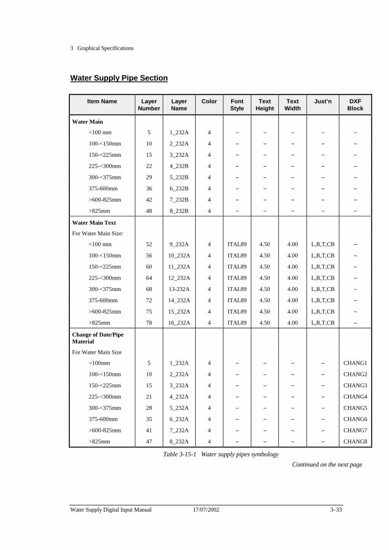
3 Graphical Specifications
Water Supply Digital Input Manual 17/07/2002 3–33
Water Supply Pipe Section
Item Name Layer Number
Layer Name
Color Font Style
Text Height
Text Width
Just’n DXF Block
Water Main
<100 mm 5 1_232A 4 − − − − −
100-<150mm 10 2_232A 4 − − − − −
150-<225mm 15 3_232A 4 − − − − −
225-<300mm 22 4_232B 4 − − − − −
300-<375mm 29 5_232B 4 − − − − −
375-600mm 36 6_232B 4 − − − − −
>600-825mm 42 7_232B 4 − − − − −
>825mm 48 8_232B 4 − − − − −
Water Main Text
For Water Main Size:
<100 mm 52 9_232A 4 ITAL89 4.50 4.00 L,R,T,CB −
100-<150mm 56 10_232A 4 ITAL89 4.50 4.00 L,R,T,CB −
150-<225mm 60 11_232A 4 ITAL89 4.50 4.00 L,R,T,CB −
225-<300mm 64 12_232A 4 ITAL89 4.50 4.00 L,R,T,CB −
300-<375mm 68 13-232A 4 ITAL89 4.50 4.00 L,R,T,CB −
375-600mm 72 14_232A 4 ITAL89 4.50 4.00 L,R,T,CB −
>600-825mm 75 15_232A 4 ITAL89 4.50 4.00 L,R,T,CB −
>825mm 78 16_232A 4 ITAL89 4.50 4.00 L,R,T,CB −
Change of Date/Pipe Material
For Water Main Size
<100mm 5 1_232A 4 − − − − CHANG1
100-<150mm 10 2_232A 4 − − − − CHANG2
150-<225mm 15 3_232A 4 − − − − CHANG3
225-<300mm 21 4_232A 4 − − − − CHANG4
300-<375mm 28 5_232A 4 − − − − CHANG5
375-600mm 35 6_232A 4 − − − − CHANG6
>600-825mm 41 7_232A 4 − − − − CHANG7
>825mm 47 8_232A 4 − − − − CHANG8
Table 3-15-1 Water supply pipes symbology Continued on the next page
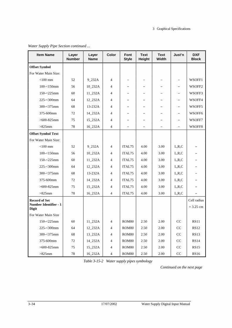
3 Graphical Specifications
3–34 17/07/2002 Water Supply Digital Input Manual
Water Supply Pipe Section continued ...
Item Name Layer Number
Layer Name
Color Font Style
Text Height
Text Width
Just’n DXF Block
Offset Symbol
For Water Main Size:
<100 mm 52 9_232A 4 − − − − WSOFF1
100-<150mm 56 10_232A 4 − − − − WSOFF2
150-<225mm 60 11_232A 4 − − − − WSOFF3
225-<300mm 64 12_232A 4 − − − − WSOFF4
300-<375mm 68 13-232A 4 − − − − WSOFF5
375-600mm 72 14_232A 4 − − − − WSOFF6
>600-825mm 75 15_232A 4 − − − − WSOFF7
>825mm 78 16_232A 4 − − − − WSOFF8
Offset Symbol Text
For Water Main Size:
<100 mm 52 9_232A 4 ITAL75 4.00 3.00 L,R,C −
100-<150mm 56 10_232A 4 ITAL75 4.00 3.00 L,R,C −
150-<225mm 60 11_232A 4 ITAL75 4.00 3.00 L,R,C −
225-<300mm 64 12_232A 4 ITAL75 4.00 3.00 L,R,C −
300-<375mm 68 13-232A 4 ITAL75 4.00 3.00 L,R,C −
375-600mm 72 14_232A 4 ITAL75 4.00 3.00 L,R,C −
>600-825mm 75 15_232A 4 ITAL75 4.00 3.00 L,R,C −
>825mm 78 16_232A 4 ITAL75 4.00 3.00 L,R,C −
Record of Set Number Identifier - 1 Digit
Cell radius
= 3.25 cm
For Water Main Size
150-<225mm 60 11_232A 4 ROM80 2.50 2.00 CC RS11
225-<300mm 64 12_232A 4 ROM80 2.50 2.00 CC RS12
300-<375mm 68 13_232A 4 ROM80 2.50 2.00 CC RS13
375-600mm 72 14_232A 4 ROM80 2.50 2.00 CC RS14
>600-825mm 75 15_232A 4 ROM80 2.50 2.00 CC RS15
>825mm 78 16_232A 4 ROM80 2.50 2.00 CC RS16
Table 3-15-2 Water supply pipes symbology Continued on the next page
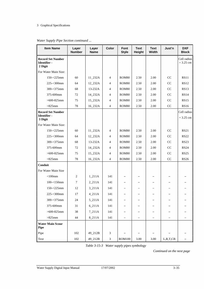
3 Graphical Specifications
Water Supply Digital Input Manual 17/07/2002 3–35
Water Supply Pipe Section continued ...
Item Name Layer Number
Layer Name
Color Font Style
Text Height
Text Width
Just’n DXF Block
Record Set Number Identifier - 2 Digit
Cell radius= 3.25 cm
For Water Main Size:
150-<225mm 60 11_232A 4 ROM80 2.50 2.00 CC RS11
225-<300mm 64 12_232A 4 ROM80 2.50 2.00 CC RS12
300-<375mm 68 13-232A 4 ROM80 2.50 2.00 CC RS13
375-600mm 72 14_232A 4 ROM80 2.50 2.00 CC RS14
>600-825mm 75 15_232A 4 ROM80 2.50 2.00 CC RS15
>825mm 78 16_232A 4 ROM80 2.50 2.00 CC RS16
Record Set Number Identifier - 3 Digit
Cell radius
= 3.25 cm
For Water Main Size:
150-<225mm 60 11_232A 4 ROM80 2.50 2.00 CC RS21
225-<300mm 64 12_232A 4 ROM80 2.50 2.00 CC RS22
300-<375mm 68 13-232A 4 ROM80 2.50 2.00 CC RS23
375-600mm 72 14_232A 4 ROM80 2.50 2.00 CC RS24
>600-825mm 75 15_232A 4 ROM80 2.50 2.00 CC RS25
>825mm 78 16_232A 4 ROM80 2.50 2.00 CC RS26
Conduit
For Water Main Size
<100mm 2 1_211A 141 − − − − −
100-<150mm 7 2_211A 141 − − − − −
150-<225mm 12 3_211A 141 − − − − −
225-<300mm 17 4_211A 141 − − − − −
300-<375mm 24 5_211A 141 − − − − −
375-600mm 31 6_211A 141 − − − − −
>600-825mm 38 7_211A 141 − − − − −
>825mm 44 8_211A 141 − − − − −
Water Main Scour Pipe
Pipe 102 49_212B 3 − − − − −
Text 102 49_212B 3 ROM100 3.00 3.00 L,R,T,CB −
Table 3-15-3 Water supply pipes symbology Continued on the next page
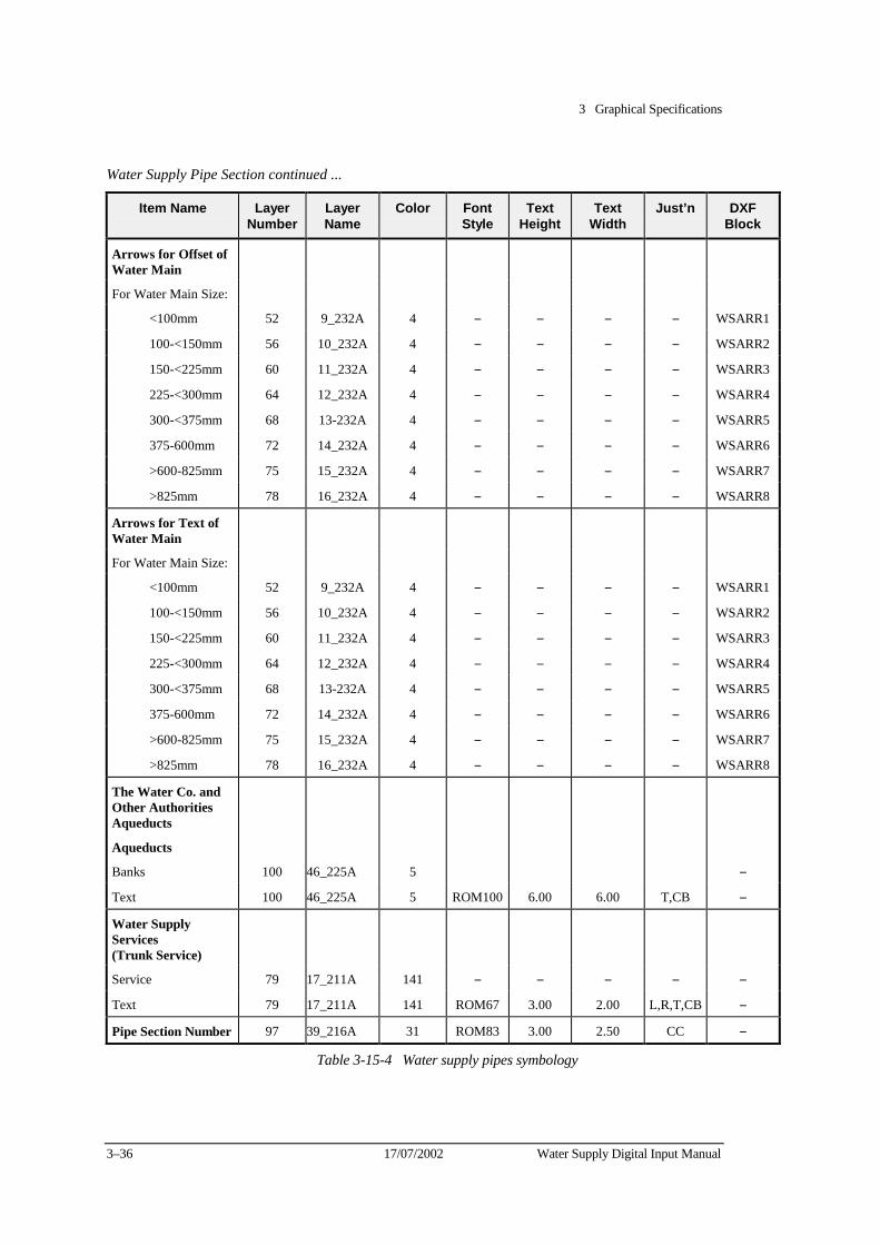
3 Graphical Specifications
3–36 17/07/2002 Water Supply Digital Input Manual
Water Supply Pipe Section continued ...
Item Name Layer Number
Layer Name
Color Font Style
Text Height
Text Width
Just’n DXF Block
Arrows for Offset of Water Main
For Water Main Size:
<100mm 52 9_232A 4 − − − − WSARR1
100-<150mm 56 10_232A 4 − − − − WSARR2
150-<225mm 60 11_232A 4 − − − − WSARR3
225-<300mm 64 12_232A 4 − − − − WSARR4
300-<375mm 68 13-232A 4 − − − − WSARR5
375-600mm 72 14_232A 4 − − − − WSARR6
>600-825mm 75 15_232A 4 − − − − WSARR7
>825mm 78 16_232A 4 − − − − WSARR8
Arrows for Text of Water Main
For Water Main Size:
<100mm 52 9_232A 4 − − − − WSARR1
100-<150mm 56 10_232A 4 − − − − WSARR2
150-<225mm 60 11_232A 4 − − − − WSARR3
225-<300mm 64 12_232A 4 − − − − WSARR4
300-<375mm 68 13-232A 4 − − − − WSARR5
375-600mm 72 14_232A 4 − − − − WSARR6
>600-825mm 75 15_232A 4 − − − − WSARR7
>825mm 78 16_232A 4 − − − − WSARR8
The Water Co. and Other Authorities Aqueducts
Aqueducts
Banks 100 46_225A 5 −
Text 100 46_225A 5 ROM100 6.00 6.00 T,CB −
Water Supply Services (Trunk Service)
Service 79 17_211A 141 − − − − −
Text 79 17_211A 141 ROM67 3.00 2.00 L,R,T,CB −
Pipe Section Number 97 39_216A 31 ROM83 3.00 2.50 CC −
Table 3-15-4 Water supply pipes symbology

3 Graphical Specifications
Water Supply Digital Input Manual 17/07/2002 3–37
Valves
Item Name Layer Number
Layer Name
Color Font Style
Text Height
Text Width
Just’n DXF Block
Valve
For Water Main Size:
<100mm 5 1_232A 4 − − − − VALVE1
100-<150mm 10 2_232A 4 − − − − VALVE2
150-<225mm 15 3_232A 4 − − − − VALVE3
225-<300mm 21 4_232A 4 − − − − VALVE4
300-<375mm 28 5_232A 4 − − − − VALVE5
375-600mm 35 6_232A 4 − − − − VALVE6
>600 - 825mm 41 7_232A 4 − − − − VALVE7
>825mm 47 8_232A 4 − − − − VALVE8
Non Return Valve (Reflux)
For Water Main Size:
<100mm 5 1_232A 4 − − − − NRVAL1
100-<150mm 10 2_232A 4 − − − − NRVAL2
150-<225mm 15 3_232A 4 − − − − NRVAL3
225-<300mm 21 4_232A 4 − − − − NRVAL4
300-<375mm 28 5_232A 4 − − − − NRVAL5
375-600mm 35 6_232A 4 − − − − NRVAL6
>600 - 825mm 41 7_232A 4 − − − − NRVAL7
>825mm 47 8_232A 4 − − − − NRVAL8
Table 3-16-1 Water supply valves symbology Continued on the next page
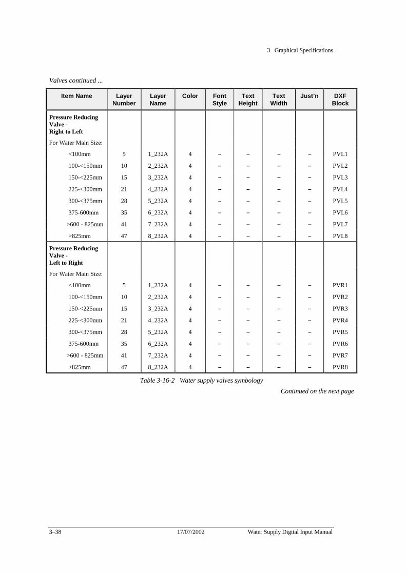
3 Graphical Specifications
3–38 17/07/2002 Water Supply Digital Input Manual
Valves continued ...
Item Name Layer Number
Layer Name
Color Font Style
Text Height
Text Width
Just’n DXF Block
Pressure Reducing Valve - Right to Left
For Water Main Size:
<100mm 5 1_232A 4 − − − − PVL1
100-<150mm 10 2_232A 4 − − − − PVL2
150-<225mm 15 3_232A 4 − − − − PVL3
225-<300mm 21 4_232A 4 − − − − PVL4
300-<375mm 28 5_232A 4 − − − − PVL5
375-600mm 35 6_232A 4 − − − − PVL6
>600 - 825mm 41 7_232A 4 − − − − PVL7
>825mm 47 8_232A 4 − − − − PVL8
Pressure Reducing Valve - Left to Right
For Water Main Size:
<100mm 5 1_232A 4 − − − − PVR1
100-<150mm 10 2_232A 4 − − − − PVR2
150-<225mm 15 3_232A 4 − − − − PVR3
225-<300mm 21 4_232A 4 − − − − PVR4
300-<375mm 28 5_232A 4 − − − − PVR5
375-600mm 35 6_232A 4 − − − − PVR6
>600 - 825mm 41 7_232A 4 − − − − PVR7
>825mm 47 8_232A 4 − − − − PVR8
Table 3-16-2 Water supply valves symbology Continued on the next page

3 Graphical Specifications
Water Supply Digital Input Manual 17/07/2002 3–39
Valves continued ...
Item Name Layer Number
Layer Name
Color Font Style
Text Height
Text Width
Just’n DXF Block
Pressure SustainingValve - Right to Left
For Water Main Size:
<100mm 5 1_232A 4 − − − − PVL1
100-<150mm 10 2_232A 4 − − − − PVL2
150-<225mm 15 3_232A 4 − − − − PVL3
225-<300mm 21 4_232A 4 − − − − PVL4
300-<375mm 28 5_232A 4 − − − − PVL5
375-600mm 35 6_232A 4 − − − − PVL6
>600 - 825mm 41 7_232A 4 − − − − PVL7
>825mm 47 8_232A 4 − − − − PVL8
Pressure SustainingValve - Left to Right
For Water Main Size:
<100mm 5 1_232A 4 − − − − PVR1
100-<150mm 10 2_232A 4 − − − − PVR2
150-<225mm 15 3_232A 4 − − − − PVR3
225-<300mm 21 4_232A 4 − − − − PVR4
300-<375mm 28 5_232A 4 − − − − PVR5
375-600mm 35 6_232A 4 − − − − PVR6
>600 - 825mm 41 7_232A 4 − − − − PVR7
>825mm 47 8_232A 4 − − − − PVR8
Table 3-16-3 Water supply valves symbology Continued on the next page
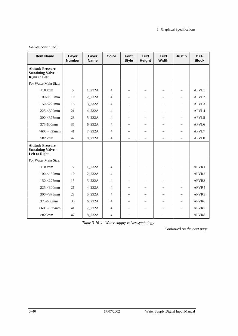
3 Graphical Specifications
3–40 17/07/2002 Water Supply Digital Input Manual
Valves continued ...
Item Name Layer Number
Layer Name
Color Font Style
Text Height
Text Width
Just’n DXF Block
Altitude Pressure Sustaining Valve - Right to Left
For Water Main Size:
<100mm 5 1_232A 4 − − − − APVL1
100-<150mm 10 2_232A 4 − − − − APVL2
150-<225mm 15 3_232A 4 − − − − APVL3
225-<300mm 21 4_232A 4 − − − − APVL4
300-<375mm 28 5_232A 4 − − − − APVL5
375-600mm 35 6_232A 4 − − − − APVL6
>600 - 825mm 41 7_232A 4 − − − − APVL7
>825mm 47 8_232A 4 − − − − APVL8
Altitude Pressure Sustaining Valve - Left to Right
For Water Main Size:
<100mm 5 1_232A 4 − − − − APVR1
100-<150mm 10 2_232A 4 − − − − APVR2
150-<225mm 15 3_232A 4 − − − − APVR3
225-<300mm 21 4_232A 4 − − − − APVR4
300-<375mm 28 5_232A 4 − − − − APVR5
375-600mm 35 6_232A 4 − − − − APVR6
>600 - 825mm 41 7_232A 4 − − − − APVR7
>825mm 47 8_232A 4 − − − − APVR8
Table 3-16-4 Water supply valves symbology Continued on the next page
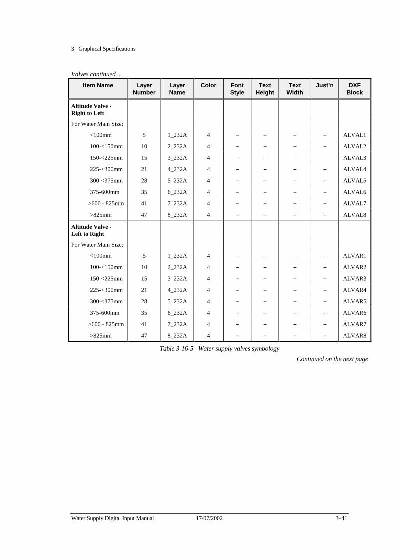
3 Graphical Specifications
Water Supply Digital Input Manual 17/07/2002 3–41
Valves continued ...
Item Name Layer Number
Layer Name
Color Font Style
Text Height
Text Width
Just’n DXF Block
Altitude Valve - Right to Left
For Water Main Size:
<100mm 5 1_232A 4 − − − − ALVAL1
100-<150mm 10 2_232A 4 − − − − ALVAL2
150-<225mm 15 3_232A 4 − − − − ALVAL3
225-<300mm 21 4_232A 4 − − − − ALVAL4
300-<375mm 28 5_232A 4 − − − − ALVAL5
375-600mm 35 6_232A 4 − − − − ALVAL6
>600 - 825mm 41 7_232A 4 − − − − ALVAL7
>825mm 47 8_232A 4 − − − − ALVAL8
Altitude Valve - Left to Right
For Water Main Size:
<100mm 5 1_232A 4 − − − − ALVAR1
100-<150mm 10 2_232A 4 − − − − ALVAR2
150-<225mm 15 3_232A 4 − − − − ALVAR3
225-<300mm 21 4_232A 4 − − − − ALVAR4
300-<375mm 28 5_232A 4 − − − − ALVAR5
375-600mm 35 6_232A 4 − − − − ALVAR6
>600 - 825mm 41 7_232A 4 − − − − ALVAR7
>825mm 47 8_232A 4 − − − − ALVAR8
Table 3-16-5 Water supply valves symbology Continued on the next page

3 Graphical Specifications
3–42 17/07/2002 Water Supply Digital Input Manual
Valves continued ...
Item Name Layer Number
Layer Name
Color Font Style
Text Height
Text Width
Just’n DXF Block
Altitude Pressure Sustaining Valve - Right to Left
For Water Main Size:
<100mm 5 1_232A 4 − − − − APVL1
100 - <150mm 10 2_232A 4 − − − − APVL2
150 - <225mm 15 3_232A 4 − − − − APVL3
225 - <300mm 21 4_232A 4 − − − − APVL4
300 - <375mm 28 5_232A 4 − − − − APVL5
375 - 600mm 35 6_232A 4 − − − − APVL6
>600 - 825mm 41 7_232A 4 − − − − APVL7
>825mm 47 8_232A 4 − − − − APVL8
Altitude Pressure Reducing Valve - Left to Right
For Water Main Size:
<100mm 5 1_232A 4 − − − − APVR1
100 - <150mm 10 2_232A 4 − − − − APVR2
150 - <225mm 15 3_232A 4 − − − − APVR3
225 - <300mm 21 4_232A 4 − − − − APVR4
300 - <375mm 28 5_232A 4 − − − − APVR5
375 - 600mm 35 6_232A 4 − − − − APVR6
>600 - 825mm 41 7_232A 4 − − − − APVR7
>825mm 47 8_232A 4 − − − − APVR8
Pressure Relief Valve
For Water Main Size:
<100mm 5 1_232A 4 − − − − PRELE1
100 - <150mm 10 2_232A 4 − − − − PRELE2
150 - <225mm 15 3_232A 4 − − − − PRELE3
225 - <300mm 21 4_232A 4 − − − − PRELE4
300 - <375mm 28 5_232A 4 − − − − PRELE5
375 - 600mm 35 6_232A 4 − − − − PRELE6
>600 - 825mm 41 7_232A 4 − − − − PRELE7
>825mm 47 8_232A 4 − − − − PRELE8
Table 3-16-6 Water supply valves symbology Continued on the next page
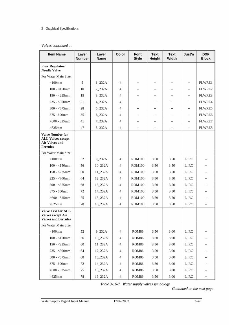
3 Graphical Specifications
Water Supply Digital Input Manual 17/07/2002 3–43
Valves continued ...
Item Name Layer Number
Layer Name
Color Font Style
Text Height
Text Width
Just’n DXF Block
Flow Regulator/ Needle Valve
For Water Main Size:
<100mm 5 1_232A 4 − − − − FLWRE1
100 - <150mm 10 2_232A 4 − − − − FLWRE2
150 - <225mm 15 3_232A 4 − − − − FLWRE3
225 - <300mm 21 4_232A 4 − − − − FLWRE4
300 - <375mm 28 5_232A 4 − − − − FLWRE5
375 - 600mm 35 6_232A 4 − − − − FLWRE6
>600 - 825mm 41 7_232A 4 − − − − FLWRE7
>825mm 47 8_232A 4 − − − − FLWRE8
Valve Number for ALL Valves except Air Valves and Ferrules
For Water Main Size:
<100mm 52 9_232A 4 ROM100 3.50 3.50 L, RC −
100 - <150mm 56 10_232A 4 ROM100 3.50 3.50 L, RC −
150 - <225mm 60 11_232A 4 ROM100 3.50 3.50 L, RC −
225 - <300mm 64 12_232A 4 ROM100 3.50 3.50 L, RC −
300 - <375mm 68 13_232A 4 ROM100 3.50 3.50 L, RC −
375 - 600mm 72 14_232A 4 ROM100 3.50 3.50 L, RC −
>600 - 825mm 75 15_232A 4 ROM100 3.50 3.50 L, RC −
>825mm 78 16_232A 4 ROM100 3.50 3.50 L, RC −
Valve Text for ALLValves except Air Valves and Ferrules
For Water Main Size:
<100mm 52 9_232A 4 ROM86 3.50 3.00 L, RC −
100 - <150mm 56 10_232A 4 ROM86 3.50 3.00 L, RC −
150 - <225mm 60 11_232A 4 ROM86 3.50 3.00 L, RC −
225 - <300mm 64 12_232A 4 ROM86 3.50 3.00 L, RC −
300 - <375mm 68 13_232A 4 ROM86 3.50 3.00 L, RC −
375 - 600mm 72 14_232A 4 ROM86 3.50 3.00 L, RC −
>600 - 825mm 75 15_232A 4 ROM86 3.50 3.00 L, RC −
>825mm 78 16_232A 4 ROM86 3.50 3.00 L, RC −
Table 3-16-7 Water supply valves symbology Continued on the next page
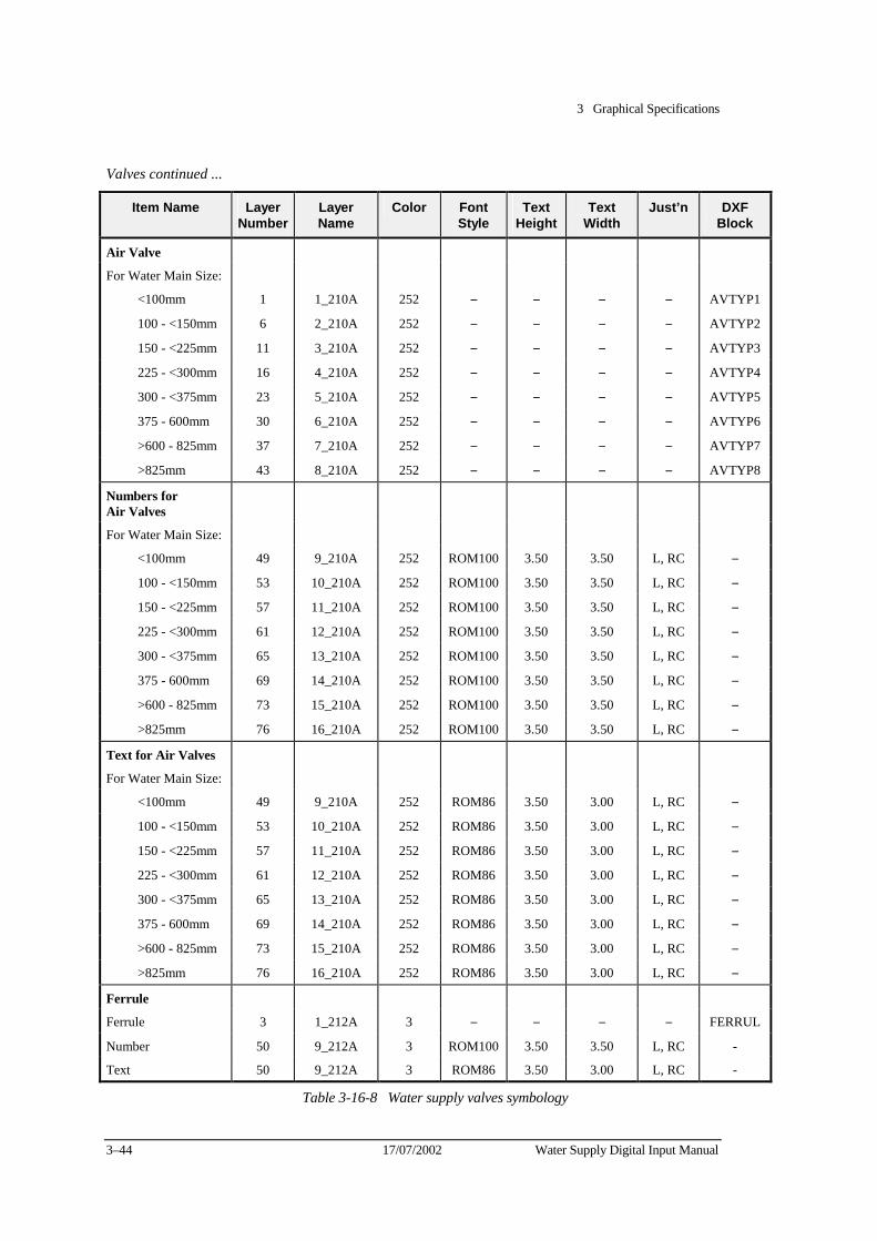
3 Graphical Specifications
3–44 17/07/2002 Water Supply Digital Input Manual
Valves continued ...
Item Name Layer Number
Layer Name
Color Font Style
Text Height
Text Width
Just’n DXF Block
Air Valve
For Water Main Size:
<100mm 1 1_210A 252 − − − − AVTYP1
100 - <150mm 6 2_210A 252 − − − − AVTYP2
150 - <225mm 11 3_210A 252 − − − − AVTYP3
225 - <300mm 16 4_210A 252 − − − − AVTYP4
300 - <375mm 23 5_210A 252 − − − − AVTYP5
375 - 600mm 30 6_210A 252 − − − − AVTYP6
>600 - 825mm 37 7_210A 252 − − − − AVTYP7
>825mm 43 8_210A 252 − − − − AVTYP8
Numbers for Air Valves
For Water Main Size:
<100mm 49 9_210A 252 ROM100 3.50 3.50 L, RC −
100 - <150mm 53 10_210A 252 ROM100 3.50 3.50 L, RC −
150 - <225mm 57 11_210A 252 ROM100 3.50 3.50 L, RC −
225 - <300mm 61 12_210A 252 ROM100 3.50 3.50 L, RC −
300 - <375mm 65 13_210A 252 ROM100 3.50 3.50 L, RC −
375 - 600mm 69 14_210A 252 ROM100 3.50 3.50 L, RC −
>600 - 825mm 73 15_210A 252 ROM100 3.50 3.50 L, RC −
>825mm 76 16_210A 252 ROM100 3.50 3.50 L, RC −
Text for Air Valves
For Water Main Size:
<100mm 49 9_210A 252 ROM86 3.50 3.00 L, RC −
100 - <150mm 53 10_210A 252 ROM86 3.50 3.00 L, RC −
150 - <225mm 57 11_210A 252 ROM86 3.50 3.00 L, RC −
225 - <300mm 61 12_210A 252 ROM86 3.50 3.00 L, RC −
300 - <375mm 65 13_210A 252 ROM86 3.50 3.00 L, RC −
375 - 600mm 69 14_210A 252 ROM86 3.50 3.00 L, RC −
>600 - 825mm 73 15_210A 252 ROM86 3.50 3.00 L, RC −
>825mm 76 16_210A 252 ROM86 3.50 3.00 L, RC −
Ferrule
Ferrule 3 1_212A 3 − − − − FERRUL
Number 50 9_212A 3 ROM100 3.50 3.50 L, RC -
Text 50 9_212A 3 ROM86 3.50 3.00 L, RC -
Table 3-16-8 Water supply valves symbology
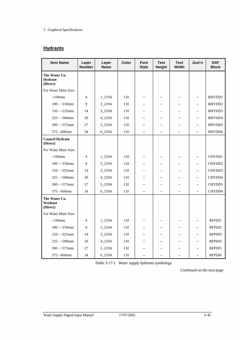
3 Graphical Specifications
Water Supply Digital Input Manual 17/07/2002 3–45
Hydrants
Item Name Layer Number
Layer Name
Color Font Style
Text Height
Text Width
Just’n DXF Block
The Water Co. Hydrant (Direct)
For Water Main Size:
<100mm 4 1_219A 110 − − − − BHYDD1
100 - <150mm 9 2_219A 110 − − − − BHYDD2
150 - <225mm 14 3_219A 110 − − − − BHYDD3
225 - <300mm 20 4_219A 110 − − − − BHYDD4
300 - <375mm 27 5_219A 110 − − − − BHYDD5
375 - 600mm 34 6_219A 110 − − − − BHYDD6
Council Hydrant (Direct)
For Water Main Size:
<100mm 4 1_219A 110 − − − − CHYDD1
100 - <150mm 9 2_219A 110 − − − − CHYDD2
150 - <225mm 14 3_219A 110 − − − − CHYDD3
225 - <300mm 20 4_219A 110 − − − − CHYDD4
300 - <375mm 27 5_219A 110 − − − − CHYDD5
375 - 600mm 34 6_219A 110 − − − − CHYDD6
The Water Co. Washout (Direct)
For Water Main Size:
<100mm 4 1_219A 110 − − − − BFPDI1
100 - <150mm 9 2_219A 110 − − − − BFPDI2
150 - <225mm 14 3_219A 110 − − − − BFPDI3
225 - <300mm 20 4_219A 110 − − − − BFPDI4
300 - <375mm 27 5_219A 110 − − − − BFPDI5
375 - 600mm 34 6_219A 110 − − − − BFPDI6
Table 3-17-1 Water supply hydrants symbology
Continued on the next page
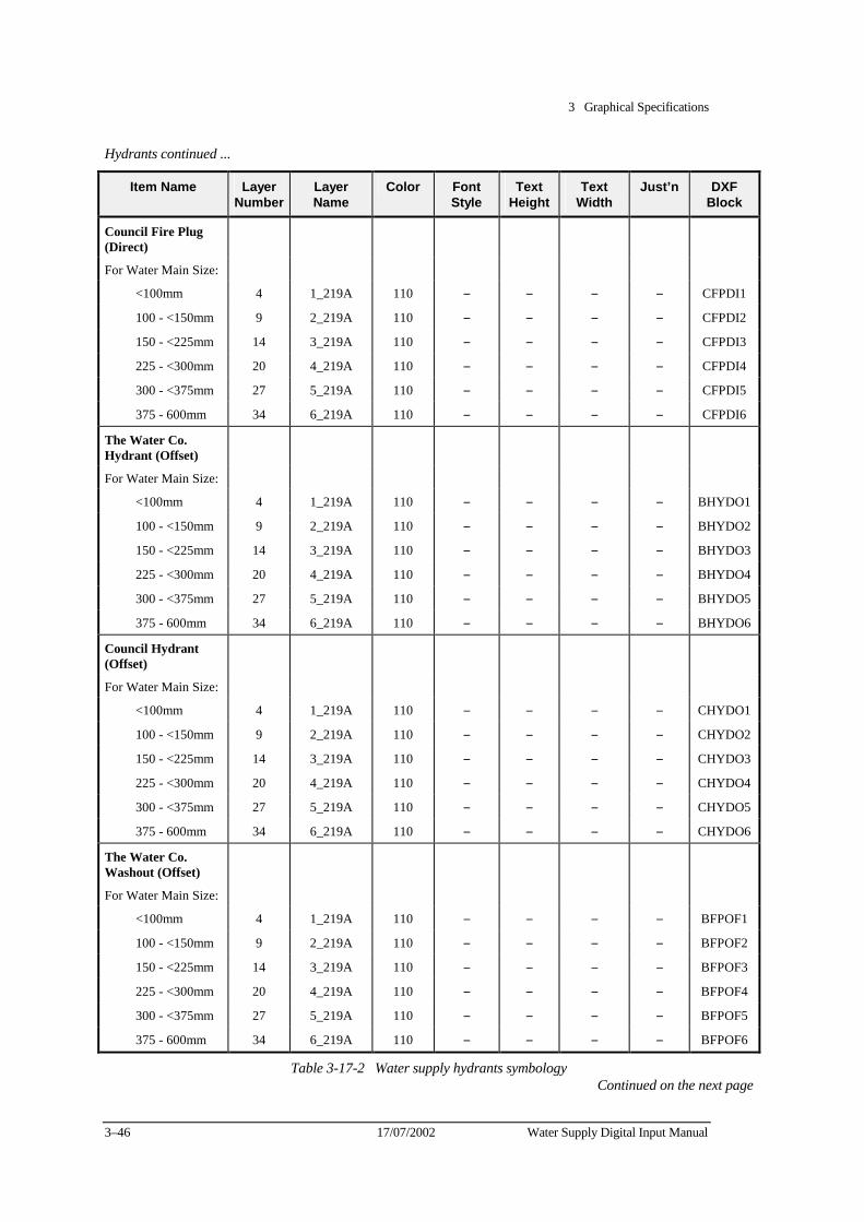
3 Graphical Specifications
3–46 17/07/2002 Water Supply Digital Input Manual
Hydrants continued ...
Item Name Layer Number
Layer Name
Color Font Style
Text Height
Text Width
Just’n DXF Block
Council Fire Plug (Direct)
For Water Main Size:
<100mm 4 1_219A 110 − − − − CFPDI1
100 - <150mm 9 2_219A 110 − − − − CFPDI2
150 - <225mm 14 3_219A 110 − − − − CFPDI3
225 - <300mm 20 4_219A 110 − − − − CFPDI4
300 - <375mm 27 5_219A 110 − − − − CFPDI5
375 - 600mm 34 6_219A 110 − − − − CFPDI6
The Water Co. Hydrant (Offset)
For Water Main Size:
<100mm 4 1_219A 110 − − − − BHYDO1
100 - <150mm 9 2_219A 110 − − − − BHYDO2
150 - <225mm 14 3_219A 110 − − − − BHYDO3
225 - <300mm 20 4_219A 110 − − − − BHYDO4
300 - <375mm 27 5_219A 110 − − − − BHYDO5
375 - 600mm 34 6_219A 110 − − − − BHYDO6
Council Hydrant (Offset)
For Water Main Size:
<100mm 4 1_219A 110 − − − − CHYDO1
100 - <150mm 9 2_219A 110 − − − − CHYDO2
150 - <225mm 14 3_219A 110 − − − − CHYDO3
225 - <300mm 20 4_219A 110 − − − − CHYDO4
300 - <375mm 27 5_219A 110 − − − − CHYDO5
375 - 600mm 34 6_219A 110 − − − − CHYDO6
The Water Co. Washout (Offset)
For Water Main Size:
<100mm 4 1_219A 110 − − − − BFPOF1
100 - <150mm 9 2_219A 110 − − − − BFPOF2
150 - <225mm 14 3_219A 110 − − − − BFPOF3
225 - <300mm 20 4_219A 110 − − − − BFPOF4
300 - <375mm 27 5_219A 110 − − − − BFPOF5
375 - 600mm 34 6_219A 110 − − − − BFPOF6
Table 3-17-2 Water supply hydrants symbology Continued on the next page
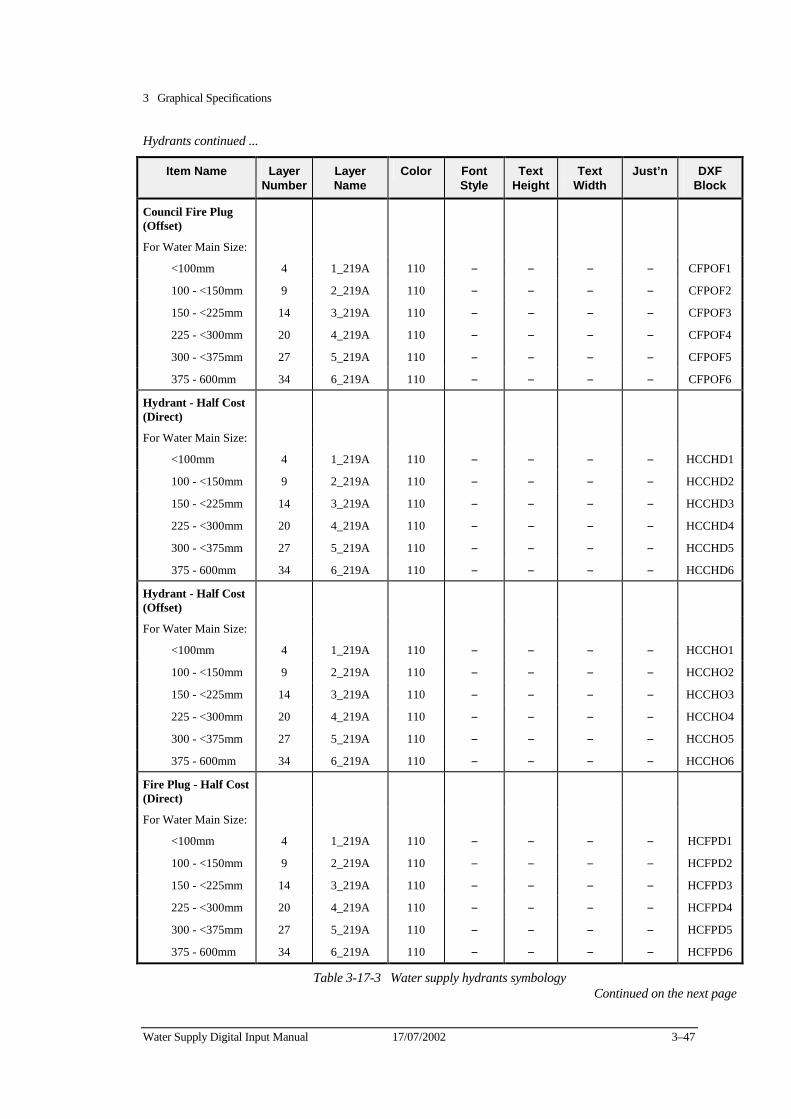
3 Graphical Specifications
Water Supply Digital Input Manual 17/07/2002 3–47
Hydrants continued ...
Item Name Layer Number
Layer Name
Color Font Style
Text Height
Text Width
Just’n DXF Block
Council Fire Plug (Offset)
For Water Main Size:
<100mm 4 1_219A 110 − − − − CFPOF1
100 - <150mm 9 2_219A 110 − − − − CFPOF2
150 - <225mm 14 3_219A 110 − − − − CFPOF3
225 - <300mm 20 4_219A 110 − − − − CFPOF4
300 - <375mm 27 5_219A 110 − − − − CFPOF5
375 - 600mm 34 6_219A 110 − − − − CFPOF6
Hydrant - Half Cost (Direct)
For Water Main Size:
<100mm 4 1_219A 110 − − − − HCCHD1
100 - <150mm 9 2_219A 110 − − − − HCCHD2
150 - <225mm 14 3_219A 110 − − − − HCCHD3
225 - <300mm 20 4_219A 110 − − − − HCCHD4
300 - <375mm 27 5_219A 110 − − − − HCCHD5
375 - 600mm 34 6_219A 110 − − − − HCCHD6
Hydrant - Half Cost (Offset)
For Water Main Size:
<100mm 4 1_219A 110 − − − − HCCHO1
100 - <150mm 9 2_219A 110 − − − − HCCHO2
150 - <225mm 14 3_219A 110 − − − − HCCHO3
225 - <300mm 20 4_219A 110 − − − − HCCHO4
300 - <375mm 27 5_219A 110 − − − − HCCHO5
375 - 600mm 34 6_219A 110 − − − − HCCHO6
Fire Plug - Half Cost (Direct)
For Water Main Size:
<100mm 4 1_219A 110 − − − − HCFPD1
100 - <150mm 9 2_219A 110 − − − − HCFPD2
150 - <225mm 14 3_219A 110 − − − − HCFPD3
225 - <300mm 20 4_219A 110 − − − − HCFPD4
300 - <375mm 27 5_219A 110 − − − − HCFPD5
375 - 600mm 34 6_219A 110 − − − − HCFPD6
Table 3-17-3 Water supply hydrants symbology Continued on the next page
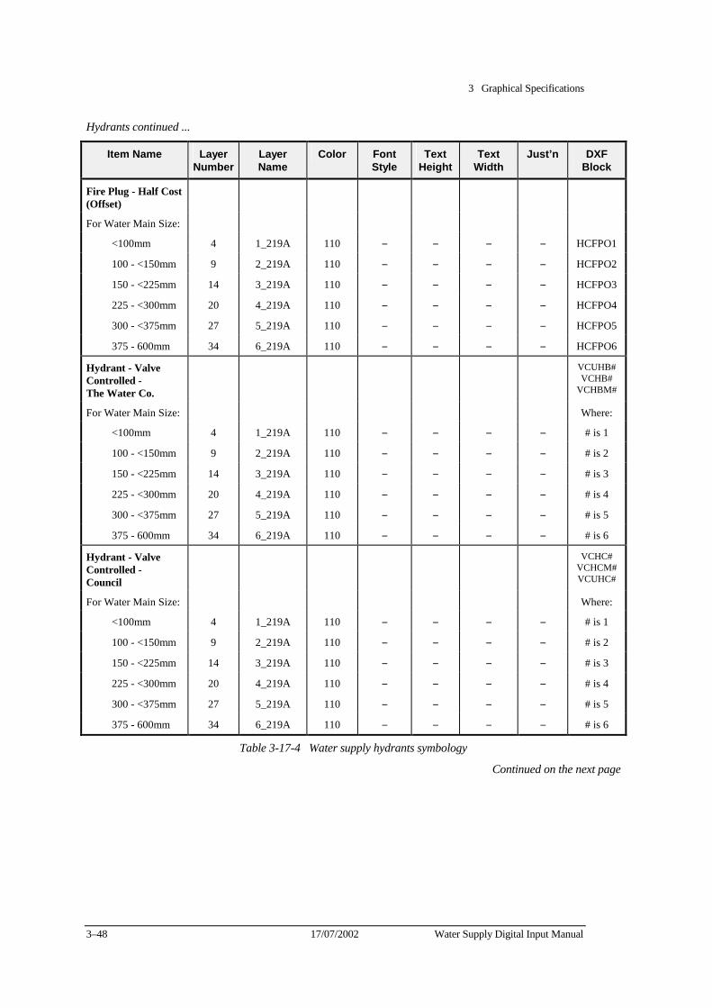
3 Graphical Specifications
3–48 17/07/2002 Water Supply Digital Input Manual
Hydrants continued ...
Item Name Layer Number
Layer Name
Color Font Style
Text Height
Text Width
Just’n DXF Block
Fire Plug - Half Cost (Offset)
For Water Main Size:
<100mm 4 1_219A 110 − − − − HCFPO1
100 - <150mm 9 2_219A 110 − − − − HCFPO2
150 - <225mm 14 3_219A 110 − − − − HCFPO3
225 - <300mm 20 4_219A 110 − − − − HCFPO4
300 - <375mm 27 5_219A 110 − − − − HCFPO5
375 - 600mm 34 6_219A 110 − − − − HCFPO6
Hydrant - Valve Controlled - The Water Co.
VCUHB#VCHB#
VCHBM#
For Water Main Size: Where:
<100mm 4 1_219A 110 − − − − # is 1
100 - <150mm 9 2_219A 110 − − − − # is 2
150 - <225mm 14 3_219A 110 − − − − # is 3
225 - <300mm 20 4_219A 110 − − − − # is 4
300 - <375mm 27 5_219A 110 − − − − # is 5
375 - 600mm 34 6_219A 110 − − − − # is 6
Hydrant - Valve Controlled - Council
VCHC# VCHCM#VCUHC#
For Water Main Size: Where:
<100mm 4 1_219A 110 − − − − # is 1
100 - <150mm 9 2_219A 110 − − − − # is 2
150 - <225mm 14 3_219A 110 − − − − # is 3
225 - <300mm 20 4_219A 110 − − − − # is 4
300 - <375mm 27 5_219A 110 − − − − # is 5
375 - 600mm 34 6_219A 110 − − − − # is 6
Table 3-17-4 Water supply hydrants symbology
Continued on the next page
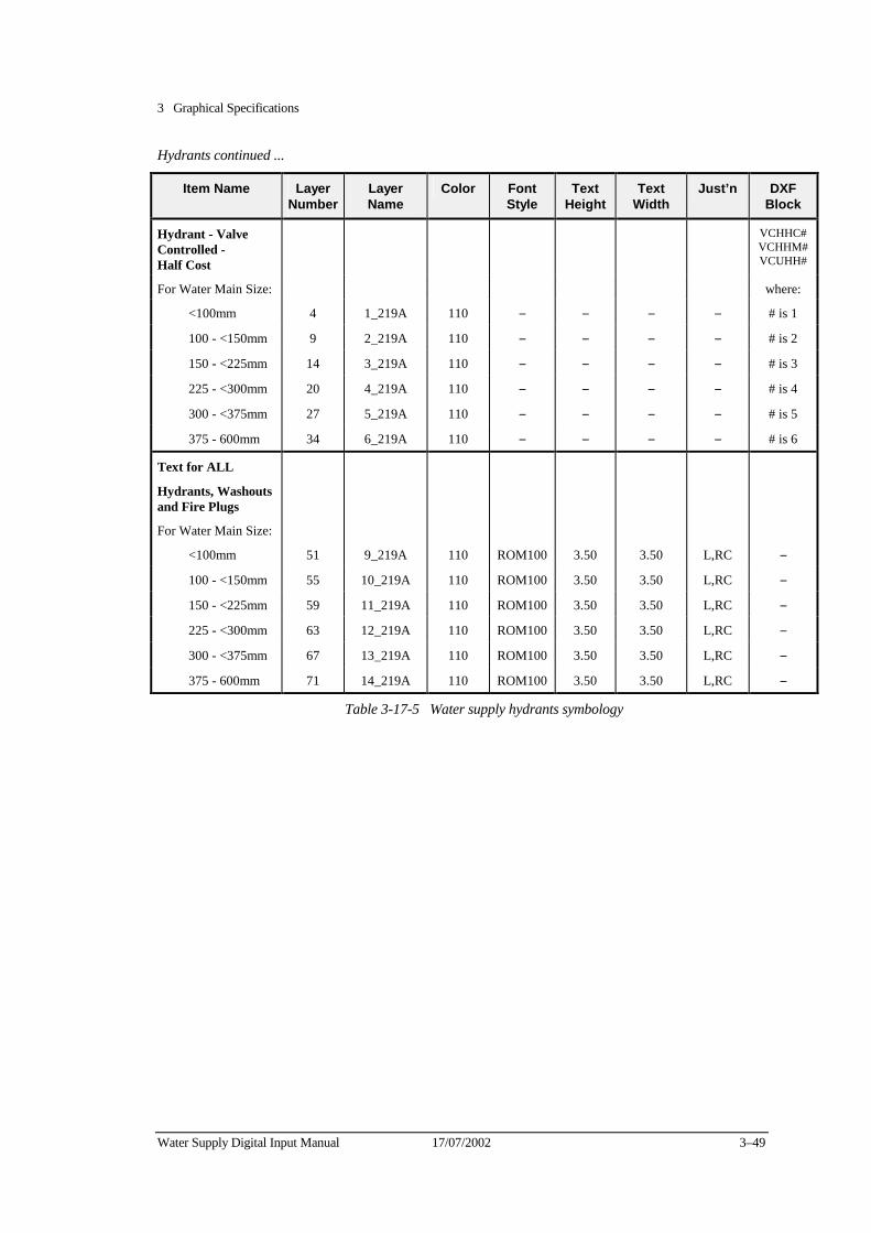
3 Graphical Specifications
Water Supply Digital Input Manual 17/07/2002 3–49
Hydrants continued ...
Item Name Layer Number
Layer Name
Color Font Style
Text Height
Text Width
Just’n DXF Block
Hydrant - Valve Controlled - Half Cost
VCHHC#VCHHM#VCUHH#
For Water Main Size: where:
<100mm 4 1_219A 110 − − − − # is 1
100 - <150mm 9 2_219A 110 − − − − # is 2
150 - <225mm 14 3_219A 110 − − − − # is 3
225 - <300mm 20 4_219A 110 − − − − # is 4
300 - <375mm 27 5_219A 110 − − − − # is 5
375 - 600mm 34 6_219A 110 − − − − # is 6
Text for ALL
Hydrants, Washouts and Fire Plugs
For Water Main Size:
<100mm 51 9_219A 110 ROM100 3.50 3.50 L,RC −
100 - <150mm 55 10_219A 110 ROM100 3.50 3.50 L,RC −
150 - <225mm 59 11_219A 110 ROM100 3.50 3.50 L,RC −
225 - <300mm 63 12_219A 110 ROM100 3.50 3.50 L,RC −
300 - <375mm 67 13_219A 110 ROM100 3.50 3.50 L,RC −
375 - 600mm 71 14_219A 110 ROM100 3.50 3.50 L,RC −
Table 3-17-5 Water supply hydrants symbology
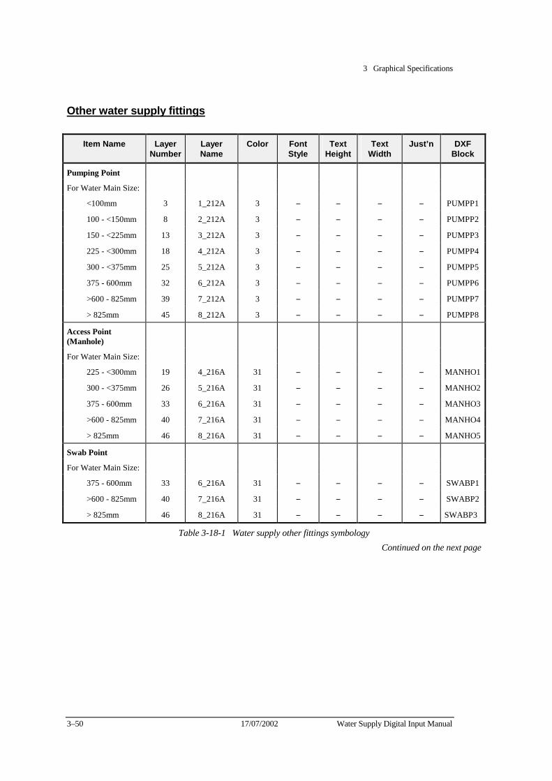
3 Graphical Specifications
3–50 17/07/2002 Water Supply Digital Input Manual
Other water supply fittings
Item Name Layer Number
Layer Name
Color Font Style
Text Height
Text Width
Just’n DXF Block
Pumping Point
For Water Main Size:
<100mm 3 1_212A 3 − − − − PUMPP1
100 - <150mm 8 2_212A 3 − − − − PUMPP2
150 - <225mm 13 3_212A 3 − − − − PUMPP3
225 - <300mm 18 4_212A 3 − − − − PUMPP4
300 - <375mm 25 5_212A 3 − − − − PUMPP5
375 - 600mm 32 6_212A 3 − − − − PUMPP6
>600 - 825mm 39 7_212A 3 − − − − PUMPP7
> 825mm 45 8_212A 3 − − − − PUMPP8
Access Point (Manhole)
For Water Main Size:
225 - <300mm 19 4_216A 31 − − − − MANHO1
300 - <375mm 26 5_216A 31 − − − − MANHO2
375 - 600mm 33 6_216A 31 − − − − MANHO3
>600 - 825mm 40 7_216A 31 − − − − MANHO4
> 825mm 46 8_216A 31 − − − − MANHO5
Swab Point
For Water Main Size:
375 - 600mm 33 6_216A 31 − − − − SWABP1
>600 - 825mm 40 7_216A 31 − − − − SWABP2
> 825mm 46 8_216A 31 − − − − SWABP3
Table 3-18-1 Water supply other fittings symbology Continued on the next page
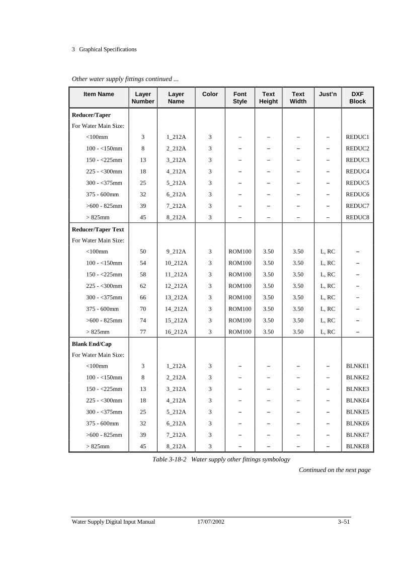
3 Graphical Specifications
Water Supply Digital Input Manual 17/07/2002 3–51
Other water supply fittings continued ...
Item Name Layer Number
Layer Name
Color Font Style
Text Height
Text Width
Just’n DXF Block
Reducer/Taper
For Water Main Size:
<100mm 3 1_212A 3 − − − − REDUC1
100 - <150mm 8 2_212A 3 − − − − REDUC2
150 - <225mm 13 3_212A 3 − − − − REDUC3
225 - <300mm 18 4_212A 3 − − − − REDUC4
300 - <375mm 25 5_212A 3 − − − − REDUC5
375 - 600mm 32 6_212A 3 − − − − REDUC6
>600 - 825mm 39 7_212A 3 − − − − REDUC7
> 825mm 45 8_212A 3 − − − − REDUC8
Reducer/Taper Text
For Water Main Size:
<100mm 50 9_212A 3 ROM100 3.50 3.50 L, RC −
100 - <150mm 54 10_212A 3 ROM100 3.50 3.50 L, RC −
150 - <225mm 58 11_212A 3 ROM100 3.50 3.50 L, RC −
225 - <300mm 62 12_212A 3 ROM100 3.50 3.50 L, RC −
300 - <375mm 66 13_212A 3 ROM100 3.50 3.50 L, RC −
375 - 600mm 70 14_212A 3 ROM100 3.50 3.50 L, RC −
>600 - 825mm 74 15_212A 3 ROM100 3.50 3.50 L, RC −
> 825mm 77 16_212A 3 ROM100 3.50 3.50 L, RC −
Blank End/Cap
For Water Main Size:
<100mm 3 1_212A 3 − − − − BLNKE1
100 - <150mm 8 2_212A 3 − − − − BLNKE2
150 - <225mm 13 3_212A 3 − − − − BLNKE3
225 - <300mm 18 4_212A 3 − − − − BLNKE4
300 - <375mm 25 5_212A 3 − − − − BLNKE5
375 - 600mm 32 6_212A 3 − − − − BLNKE6
>600 - 825mm 39 7_212A 3 − − − − BLNKE7
> 825mm 45 8_212A 3 − − − − BLNKE8
Table 3-18-2 Water supply other fittings symbology Continued on the next page
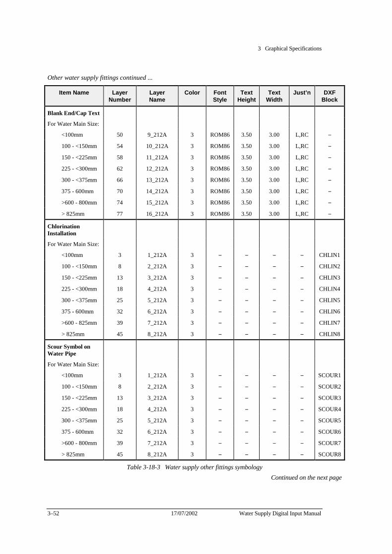
3 Graphical Specifications
3–52 17/07/2002 Water Supply Digital Input Manual
Other water supply fittings continued ...
Item Name Layer Number
Layer Name
Color Font Style
Text Height
Text Width
Just’n DXF Block
Blank End/Cap Text
For Water Main Size:
<100mm 50 9_212A 3 ROM86 3.50 3.00 L,RC −
100 - <150mm 54 10_212A 3 ROM86 3.50 3.00 L,RC −
150 - <225mm 58 11_212A 3 ROM86 3.50 3.00 L,RC −
225 - <300mm 62 12_212A 3 ROM86 3.50 3.00 L,RC −
300 - <375mm 66 13_212A 3 ROM86 3.50 3.00 L,RC −
375 - 600mm 70 14_212A 3 ROM86 3.50 3.00 L,RC −
>600 - 800mm 74 15_212A 3 ROM86 3.50 3.00 L,RC −
> 825mm 77 16_212A 3 ROM86 3.50 3.00 L,RC −
Chlorination Installation
For Water Main Size:
<100mm 3 1_212A 3 − − − − CHLIN1
100 - <150mm 8 2_212A 3 − − − − CHLIN2
150 - <225mm 13 3_212A 3 − − − − CHLIN3
225 - <300mm 18 4_212A 3 − − − − CHLIN4
300 - <375mm 25 5_212A 3 − − − − CHLIN5
375 - 600mm 32 6_212A 3 − − − − CHLIN6
>600 - 825mm 39 7_212A 3 − − − − CHLIN7
> 825mm 45 8_212A 3 − − − − CHLIN8
Scour Symbol on Water Pipe
For Water Main Size:
<100mm 3 1_212A 3 − − − − SCOUR1
100 - <150mm 8 2_212A 3 − − − − SCOUR2
150 - <225mm 13 3_212A 3 − − − − SCOUR3
225 - <300mm 18 4_212A 3 − − − − SCOUR4
300 - <375mm 25 5_212A 3 − − − − SCOUR5
375 - 600mm 32 6_212A 3 − − − − SCOUR6
>600 - 800mm 39 7_212A 3 − − − − SCOUR7
> 825mm 45 8_212A 3 − − − − SCOUR8
Table 3-18-3 Water supply other fittings symbology Continued on the next page
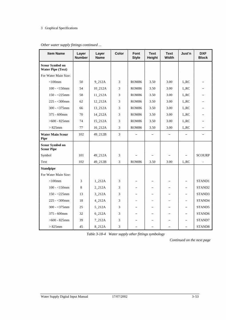
3 Graphical Specifications
Water Supply Digital Input Manual 17/07/2002 3–53
Other water supply fittings continued ...
Item Name Layer Number
Layer Name
Color Font Style
Text Height
Text Width
Just’n DXF Block
Scour Symbol on Water Pipe (Text)
For Water Main Size:
<100mm 50 9_212A 3 ROM86 3.50 3.00 L,RC −
100 - <150mm 54 10_212A 3 ROM86 3.50 3.00 L,RC −
150 - <225mm 58 11_212A 3 ROM86 3.50 3.00 L,RC −
225 - <300mm 62 12_212A 3 ROM86 3.50 3.00 L,RC −
300 - <375mm 66 13_212A 3 ROM86 3.50 3.00 L,RC −
375 - 600mm 70 14_212A 3 ROM86 3.50 3.00 L,RC −
>600 - 825mm 74 15_212A 3 ROM86 3.50 3.00 L,RC −
> 825mm 77 16_212A 3 ROM86 3.50 3.00 L,RC −
Water Main Scour Pipe
102 49_212B 3 − − − − −
Scour Symbol on Scour Pipe
Symbol 101 49_212A 3 − − − − SCOURP
Text 102 49_212B 3 ROM86 3.50 3.00 L,RC -
Standpipe
For Water Main Size:
<100mm 3 1_212A 3 − − − − STAND1
100 - <150mm 8 2_212A 3 − − − − STAND2
150 - <225mm 13 3_212A 3 − − − − STAND3
225 - <300mm 18 4_212A 3 − − − − STAND4
300 - <375mm 25 5_212A 3 − − − − STAND5
375 - 600mm 32 6_212A 3 − − − − STAND6
>600 - 825mm 39 7_212A 3 − − − − STAND7
> 825mm 45 8_212A 3 − − − − STAND8
Table 3-18-4 Water supply other fittings symbology Continued on the next page
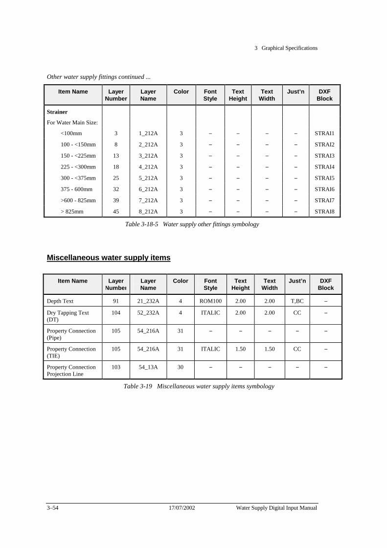
3 Graphical Specifications
3–54 17/07/2002 Water Supply Digital Input Manual
Other water supply fittings continued ...
Item Name Layer Number
Layer Name
Color Font Style
Text Height
Text Width
Just’n DXF Block
Strainer
For Water Main Size:
<100mm 3 1_212A 3 − − − − STRAI1
100 - <150mm 8 2_212A 3 − − − − STRAI2
150 - <225mm 13 3_212A 3 − − − − STRAI3
225 - <300mm 18 4_212A 3 − − − − STRAI4
300 - <375mm 25 5_212A 3 − − − − STRAI5
375 - 600mm 32 6_212A 3 − − − − STRAI6
>600 - 825mm 39 7_212A 3 − − − − STRAI7
> 825mm 45 8_212A 3 − − − − STRAI8
Table 3-18-5 Water supply other fittings symbology
Miscellaneous water supply items
Item Name Layer Number
Layer Name
Color Font Style
Text Height
Text Width
Just’n DXF Block
Depth Text 91 21_232A 4 ROM100 2.00 2.00 T,BC −
Dry Tapping Text (DT)
104 52_232A 4 ITALIC 2.00 2.00 CC −
Property Connection (Pipe)
105 54_216A 31 − − − − −
Property Connection (TIE)
105 54_216A 31 ITALIC 1.50 1.50 CC −
Property Connection Projection Line
103 54_13A 30 − − − − −
Table 3-19 Miscellaneous water supply items symbology
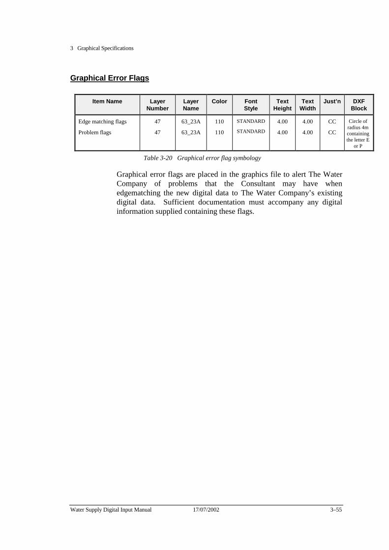
3 Graphical Specifications
Water Supply Digital Input Manual 17/07/2002 3–55
Graphical Error Flags
Item Name Layer Number
Layer Name
Color Font Style
Text Height
Text Width
Just’n DXF Block
Edge matching flags
Problem flags
47
47
63_23A
63_23A
110
110
STANDARD
STANDARD
4.00
4.00
4.00
4.00
CC
CC
Circle of radius 4m containing the letter E
or P
Table 3-20 Graphical error flag symbology
Graphical error flags are placed in the graphics file to alert The Water Company of problems that the Consultant may have when edgematching the new digital data to The Water Company’s existing digital data. Sufficient documentation must accompany any digital information supplied containing these flags.
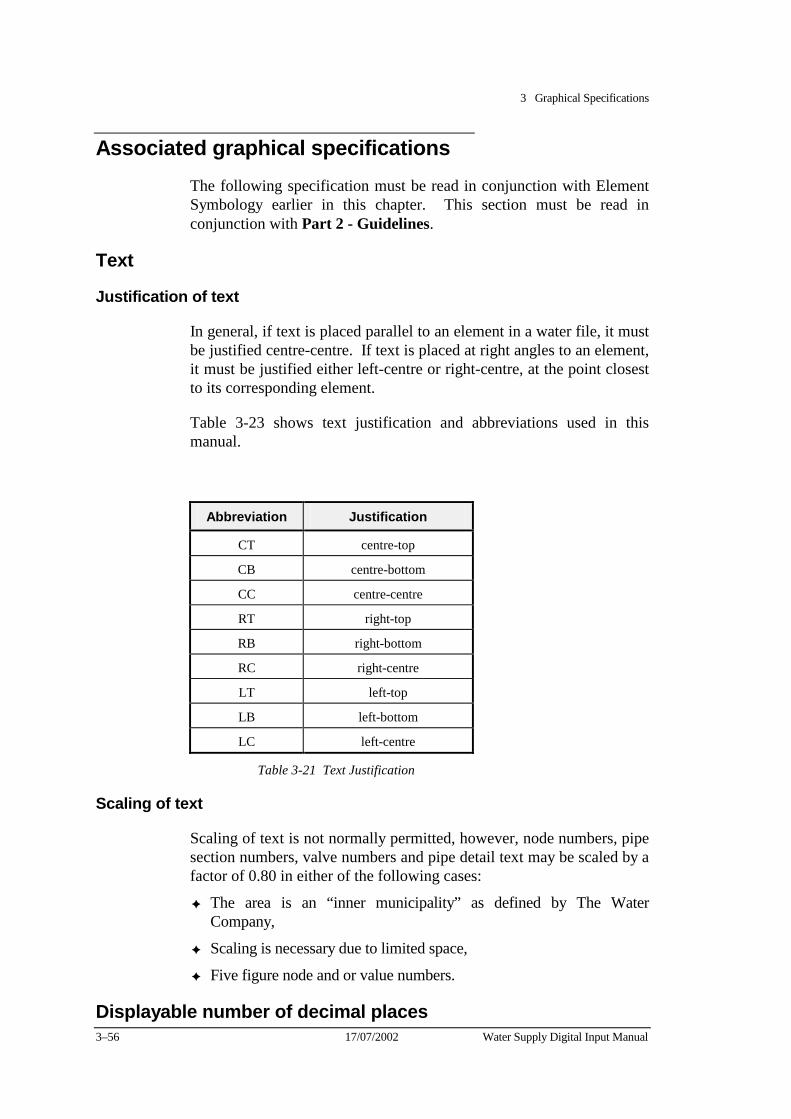
3 Graphical Specifications
3–56 17/07/2002 Water Supply Digital Input Manual
Associated graphical specifications The following specification must be read in conjunction with Element Symbology earlier in this chapter. This section must be read in conjunction with Part 2 - Guidelines.
Text
Justification of text
In general, if text is placed parallel to an element in a water file, it must be justified centre-centre. If text is placed at right angles to an element, it must be justified either left-centre or right-centre, at the point closest to its corresponding element.
Table 3-23 shows text justification and abbreviations used in this manual.
Abbreviation Justification
CT centre-top
CB centre-bottom
CC centre-centre
RT right-top
RB right-bottom
RC right-centre
LT left-top
LB left-bottom
LC left-centre
Table 3-21 Text Justification
Scaling of text
Scaling of text is not normally permitted, however, node numbers, pipe section numbers, valve numbers and pipe detail text may be scaled by a factor of 0.80 in either of the following cases:
✦ The area is an “inner municipality” as defined by The Water Company,
✦ Scaling is necessary due to limited space,
✦ Five figure node and or value numbers.
Displayable number of decimal places
3 Graphical Specifications
Water Supply Digital Input Manual 17/07/2002 3–57
All water main offset ties are to be displayed to one decimal place.
All property connection ties are to be displayed to two decimal places.
All depths are to be displayed to two decimal places.
All nominal pipe sizes are to be displayed in millimetres.
Water cells Cells are standard symbols used to represent particular elements. Figure 3-1 is a graphical listing of all cells relating to water data capture. These are all in the MicroStation Cell Library called FISCELL.CEL, which is available from the Water Company.
The DXF blocks used in the dxf graphical files are available from the Water Company as well. Their names are similar to those used inthe cell library and are easily identifiable. Sample plots showing the typical use and placement of water cells are included in Appendix D and E.

3 Graphical Specifications
3–58 17/07/2002 Water Supply Digital Input Manual
WATER CELL LIBRARY
1 OF 3
Figure 3-1
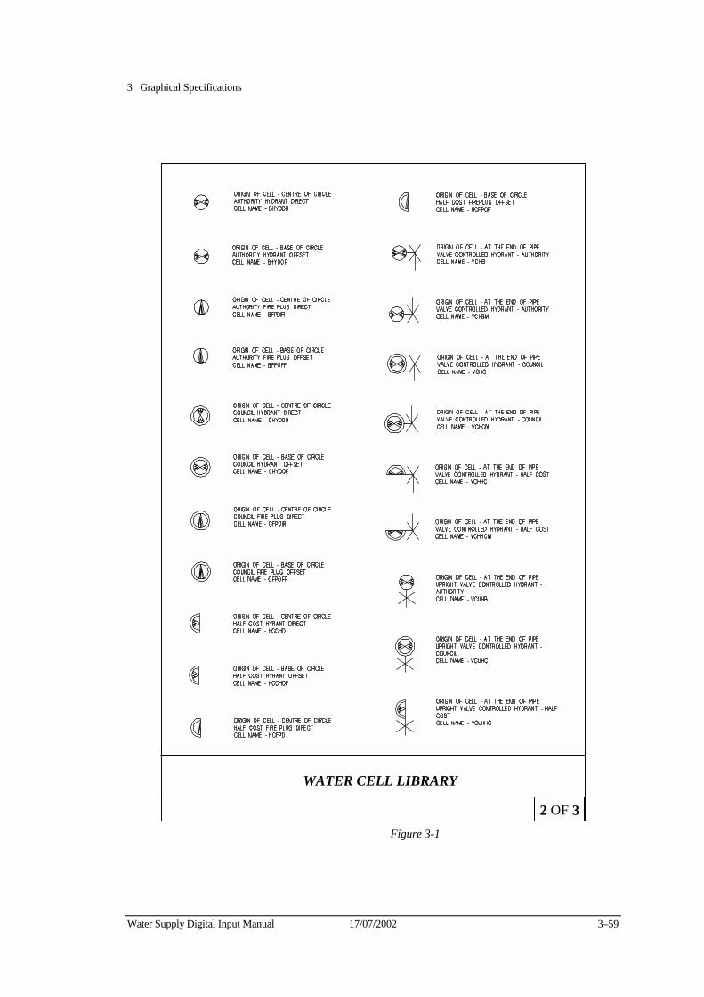
3 Graphical Specifications
Water Supply Digital Input Manual 17/07/2002 3–59
WATER CELL LIBRARY
2 OF 3
Figure 3-1
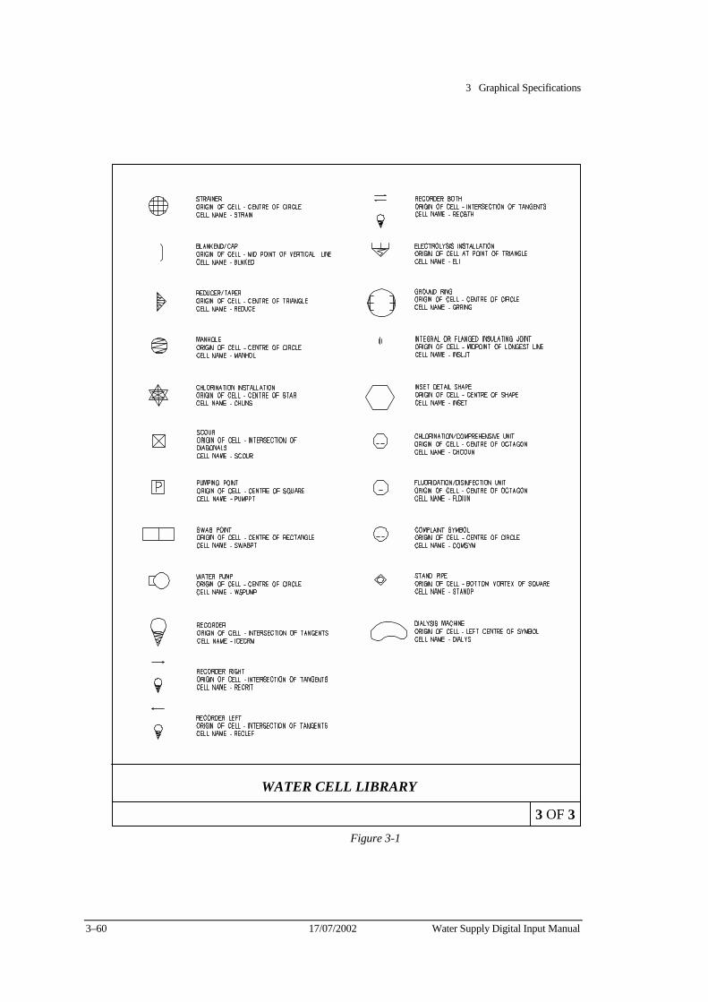
3 Graphical Specifications
3–60 17/07/2002 Water Supply Digital Input Manual
WATER CELL LIBRARY
3 OF 3
Figure 3-1

Part 2 Guidelines


Water Supply Digital Input Manual 17/07/2002 4–1
Chapter 4 Nodes This Chapter describes the requirements for the graphical and database entry of nodes.
Nodes are placed in graphics and are always linked to the database. They divide the pipe network into smaller units and their position is recorded in the database with AMG co-ordinates.
Nodes are usually located at pipe intersections and at file or municipal boundaries. It is important to note that pipe sections between nodes may not necessarily have the same characteristics throughout.
Node definitions Every water main must have an owner and connect node
Owner nodes
An owner node is placed on the first section of pipe placed. This becomes the owner of the particular pipe. An owner node may own more than one pipe section, if this is the case then pipe sections will have different pipe numbers. The number of this node is used to produce the pipe section owner id.
Connect nodes
A connect node is placed at the other end of the pipe section mentioned in the above paragraph. There are exceptions to this rule (eg Courts - where the connect node number is the same as the owner node number) which are covered in this chapter.
Note: Nodes are placed in graphics using the FIS Cell called WSNODE. The matter of owner and connect node is only related to the database records and not graphics.
4 Nodes
17/07/2002 Water Supply Digital Input Manual 4–2
Node numbers Node numbers will be issued upon request by the Water Company. Nodes should be numbered sequentially, where possible.
Do not change the specified level, rotate, or scale node numbers, except for a five figure node, pipe section and valve numbers which should be scaled down to 80% of the original size.
The node numbers must be placed within the road, where possible, with an orientation of 0 degrees (horizontal). The number must be preceded by a “+” symbol.
If there is no node placed on the end of a water main, the connect node number (for database attribute values) must be the same as the owner node number.
This would generally occur in a court bowl, dead-end street or very short section of pipe.
In general:
✦ A node must be placed where two pipes intersect,
✦ Place node numbers in the road reserve wherever possible,
✦ One node may act as both the owner and connect node in courts, bypasses and blank ended pipes.
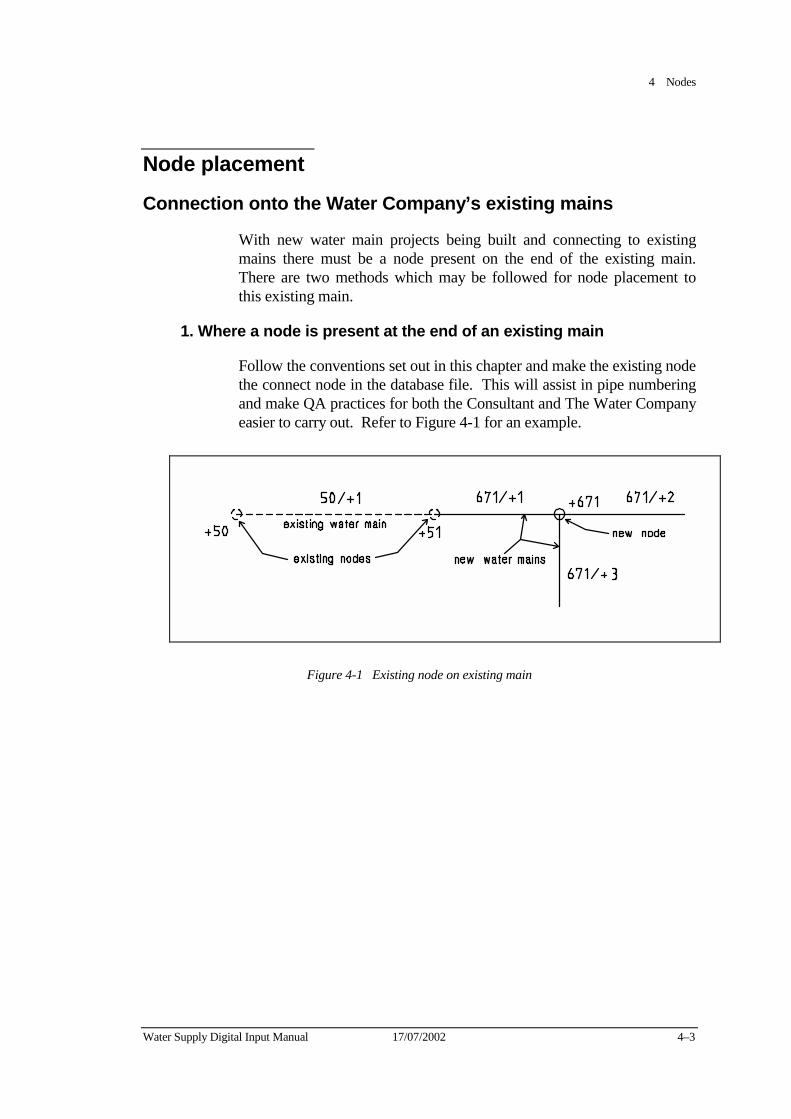
4 Nodes
Water Supply Digital Input Manual 17/07/2002 4–3
Node placement
Connection onto the Water Company’s existing mains
With new water main projects being built and connecting to existing mains there must be a node present on the end of the existing main. There are two methods which may be followed for node placement to this existing main.
1. Where a node is present at the end of an existing main
Follow the conventions set out in this chapter and make the existing node the connect node in the database file. This will assist in pipe numbering and make QA practices for both the Consultant and The Water Company easier to carry out. Refer to Figure 4-1 for an example.
Figure 4-1 Existing node on existing main
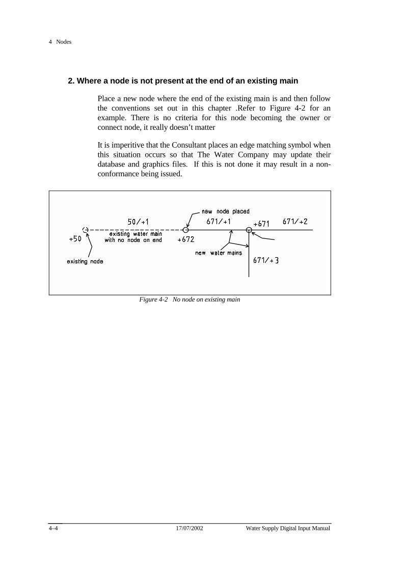
4 Nodes
17/07/2002 Water Supply Digital Input Manual 4–4
2. Where a node is not present at the end of an existing main
Place a new node where the end of the existing main is and then follow the conventions set out in this chapter .Refer to Figure 4-2 for an example. There is no criteria for this node becoming the owner or connect node, it really doesn’t matter
It is imperitive that the Consultant places an edge matching symbol when this situation occurs so that The Water Company may update their database and graphics files. If this is not done it may result in a non-conformance being issued.
Figure 4-2 No node on existing main
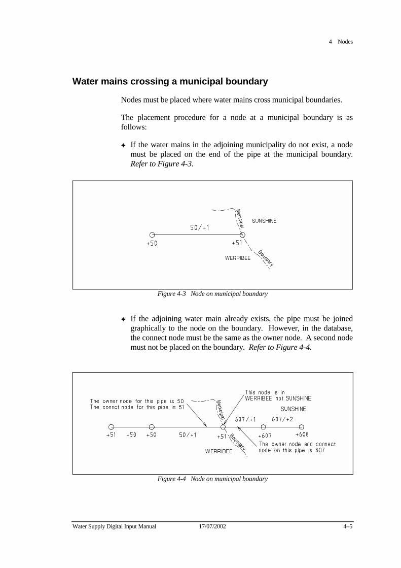
4 Nodes
Water Supply Digital Input Manual 17/07/2002 4–5
Water mains crossing a municipal boundary
Nodes must be placed where water mains cross municipal boundaries.
The placement procedure for a node at a municipal boundary is as follows:
✦ If the water mains in the adjoining municipality do not exist, a node must be placed on the end of the pipe at the municipal boundary. Refer to Figure 4-3.
Figure 4-3 Node on municipal boundary
✦ If the adjoining water main already exists, the pipe must be joined graphically to the node on the boundary. However, in the database, the connect node must be the same as the owner node. A second node must not be placed on the boundary. Refer to Figure 4-4.
Figure 4-4 Node on municipal boundary
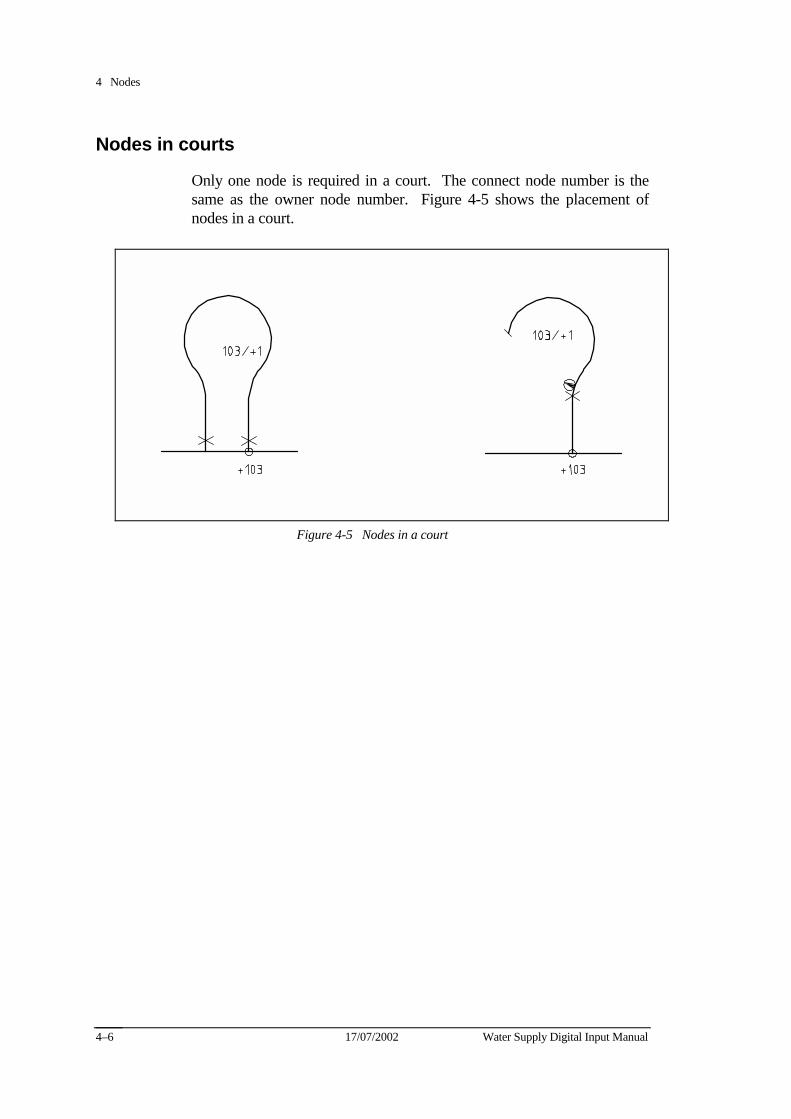
4 Nodes
17/07/2002 Water Supply Digital Input Manual 4–6
Nodes in courts
Only one node is required in a court. The connect node number is the same as the owner node number. Figure 4-5 shows the placement of nodes in a court.
Figure 4-5 Nodes in a court
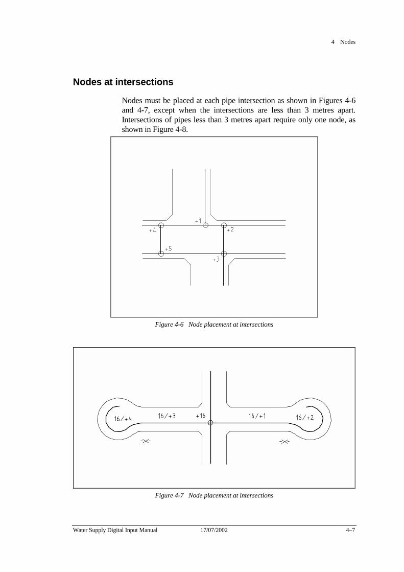
4 Nodes
Water Supply Digital Input Manual 17/07/2002 4–7
Nodes at intersections
Nodes must be placed at each pipe intersection as shown in Figures 4-6 and 4-7, except when the intersections are less than 3 metres apart. Intersections of pipes less than 3 metres apart require only one node, as shown in Figure 4-8.
Figure 4-6 Node placement at intersections
Figure 4-7 Node placement at intersections
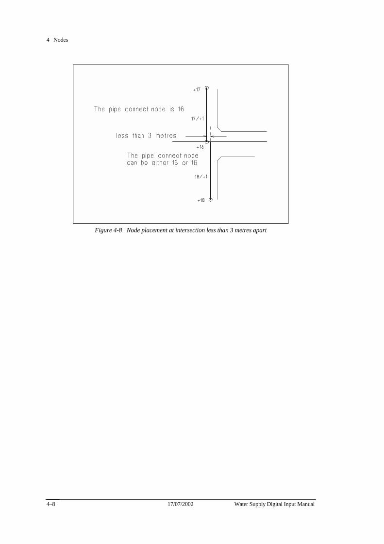
4 Nodes
17/07/2002 Water Supply Digital Input Manual 4–8
Figure 4-8 Node placement at intersection less than 3 metres apart
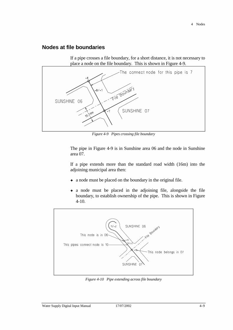
4 Nodes
Water Supply Digital Input Manual 17/07/2002 4–9
Nodes at file boundaries
If a pipe crosses a file boundary, for a short distance, it is not necessary to place a node on the file boundary. This is shown in Figure 4-9.
Figure 4-9 Pipes crossing file boundary
The pipe in Figure 4-9 is in Sunshine area 06 and the node in Sunshine area 07.
If a pipe extends more than the standard road width (16m) into the adjoining municipal area then:
✦ a node must be placed on the boundary in the original file.
✦ a node must be placed in the adjoining file, alongside the file boundary, to establish ownership of the pipe. This is shown in Figure 4-10.
Figure 4-10 Pipe extending across file boundary
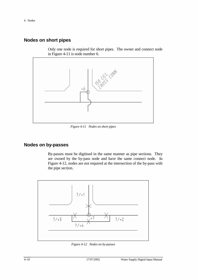
4 Nodes
17/07/2002 Water Supply Digital Input Manual 4–10
Nodes on short pipes
Only one node is required for short pipes. The owner and connect node in Figure 4-11 is node number 6.
Figure 4-11 Nodes on short pipes
Nodes on by-passes
By-passes must be digitised in the same manner as pipe sections. They are owned by the by-pass node and have the same connect node. In Figure 4-12, nodes are not required at the intersection of the by-pass with the pipe section.
Figure 4-12 Nodes on by-passes
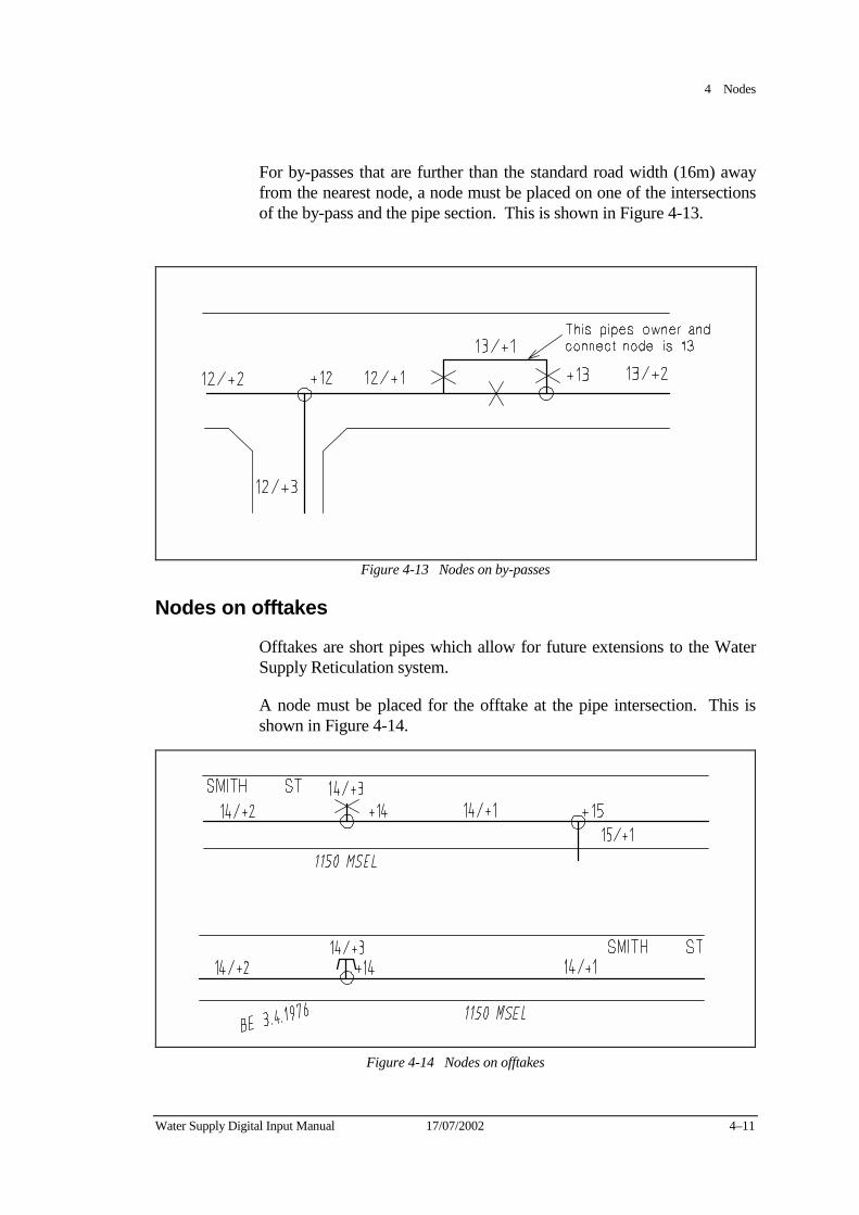
4 Nodes
Water Supply Digital Input Manual 17/07/2002 4–11
For by-passes that are further than the standard road width (16m) away from the nearest node, a node must be placed on one of the intersections of the by-pass and the pipe section. This is shown in Figure 4-13.
Figure 4-13 Nodes on by-passes
Nodes on offtakes
Offtakes are short pipes which allow for future extensions to the Water Supply Reticulation system.
A node must be placed for the offtake at the pipe intersection. This is shown in Figure 4-14.
Figure 4-14 Nodes on offtakes

4 Nodes
17/07/2002 Water Supply Digital Input Manual 4–12
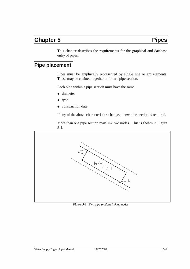
Water Supply Digital Input Manual 17/07/2002 5–1
Chapter 5 Pipes This chapter describes the requirements for the graphical and database entry of pipes.
Pipe placement Pipes must be graphically represented by single line or arc elements. These may be chained together to form a pipe section.
Each pipe within a pipe section must have the same:
✦ diameter
✦ type
✦ construction date
If any of the above characteristics change, a new pipe section is required.
More than one pipe section may link two nodes. This is shown in Figure 5-1.
Figure 5-1 Two pipe sections linking nodes
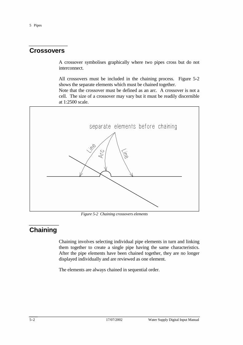
5 Pipes
17/07/2002 Water Supply Digital Input Manual 5–2
Crossovers A crossover symbolises graphically where two pipes cross but do not interconnect.
All crossovers must be included in the chaining process. Figure 5-2 shows the separate elements which must be chained together. Note that the crossover must be defined as an arc. A crossover is not a cell. The size of a crossover may vary but it must be readily discernible at 1:2500 scale.
Figure 5-2 Chaining crossovers elements
Chaining Chaining involves selecting individual pipe elements in turn and linking them together to create a single pipe having the same characteristics. After the pipe elements have been chained together, they are no longer displayed individually and are reviewed as one element.
The elements are always chained in sequential order.
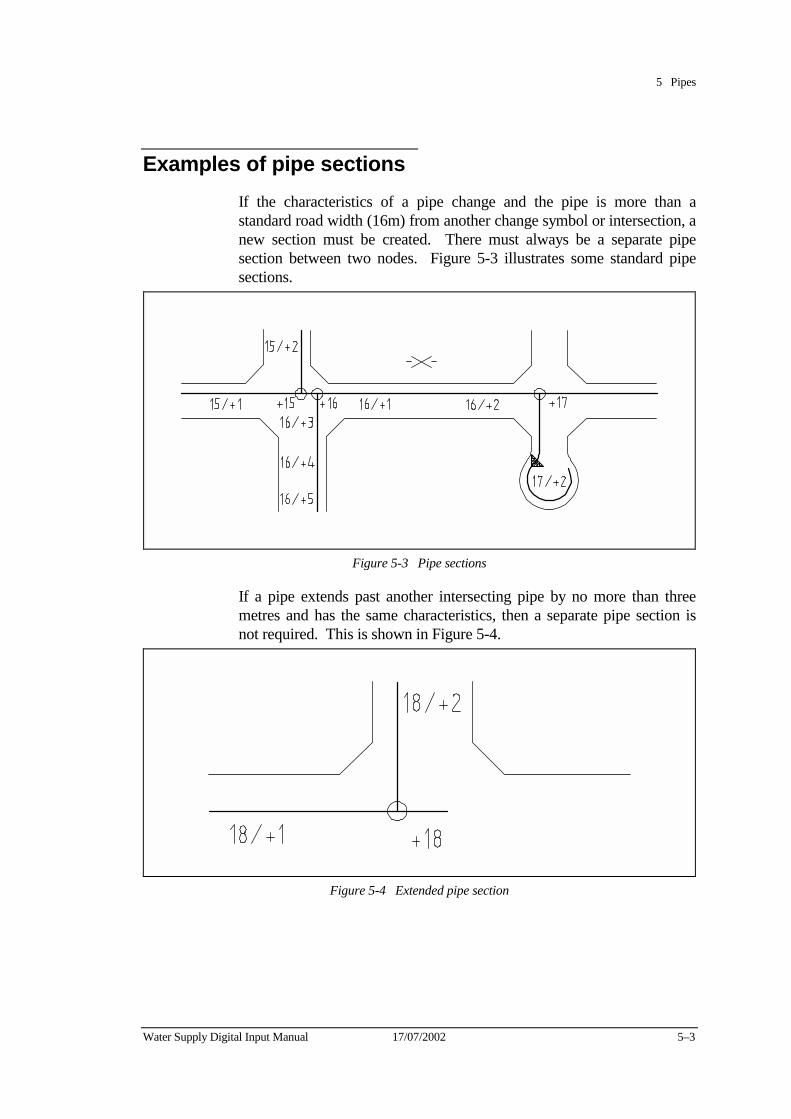
5 Pipes
Water Supply Digital Input Manual 17/07/2002 5–3
Examples of pipe sections If the characteristics of a pipe change and the pipe is more than a standard road width (16m) from another change symbol or intersection, a new section must be created. There must always be a separate pipe section between two nodes. Figure 5-3 illustrates some standard pipe sections.
Figure 5-3 Pipe sections
If a pipe extends past another intersecting pipe by no more than three metres and has the same characteristics, then a separate pipe section is not required. This is shown in Figure 5-4.
Figure 5-4 Extended pipe section
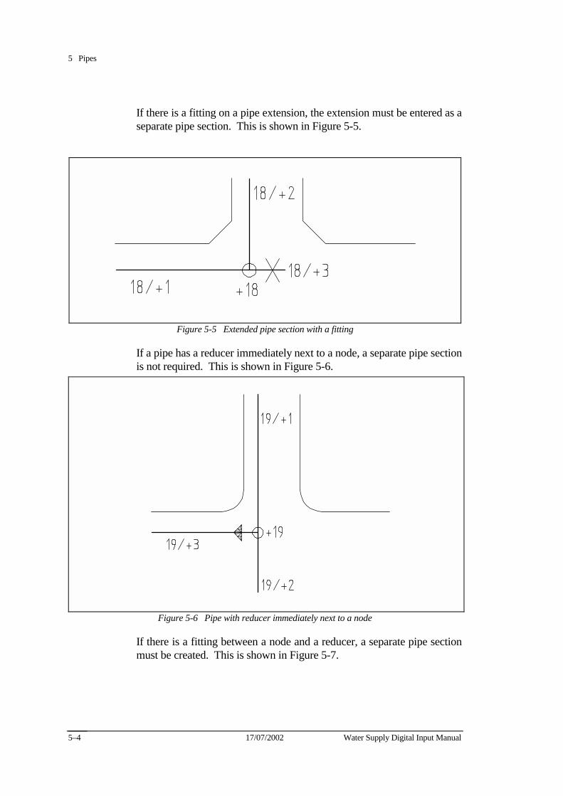
5 Pipes
17/07/2002 Water Supply Digital Input Manual 5–4
If there is a fitting on a pipe extension, the extension must be entered as a separate pipe section. This is shown in Figure 5-5.
Figure 5-5 Extended pipe section with a fitting
If a pipe has a reducer immediately next to a node, a separate pipe section is not required. This is shown in Figure 5-6.
Figure 5-6 Pipe with reducer immediately next to a node
If there is a fitting between a node and a reducer, a separate pipe section must be created. This is shown in Figure 5-7.
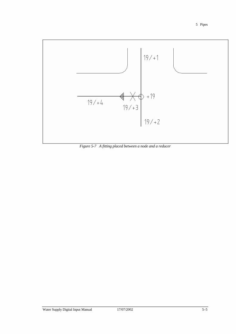
5 Pipes
Water Supply Digital Input Manual 17/07/2002 5–5
Figure 5-7 A fitting placed between a node and a reducer
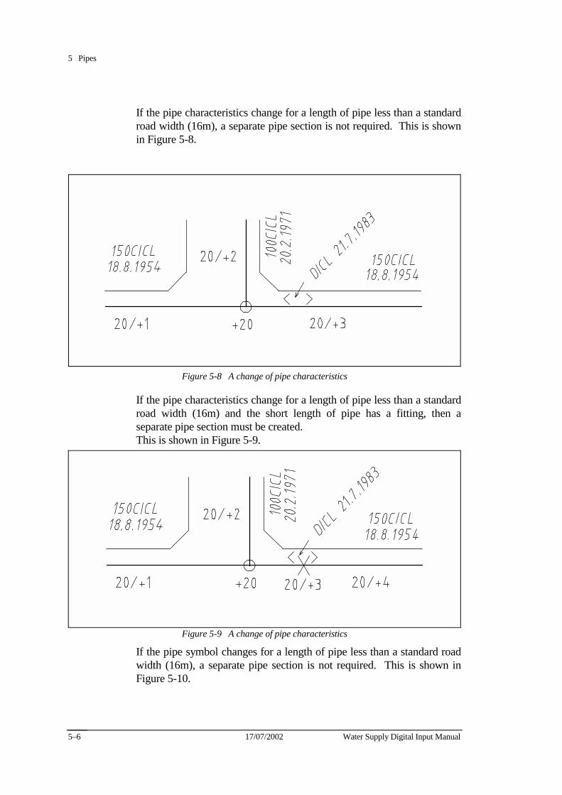
5 Pipes
17/07/2002 Water Supply Digital Input Manual 5–6
If the pipe characteristics change for a length of pipe less than a standard road width (16m), a separate pipe section is not required. This is shown in Figure 5-8.
Figure 5-8 A change of pipe characteristics
If the pipe characteristics change for a length of pipe less than a standard road width (16m) and the short length of pipe has a fitting, then a separate pipe section must be created. This is shown in Figure 5-9.
Figure 5-9 A change of pipe characteristics
If the pipe symbol changes for a length of pipe less than a standard road width (16m), a separate pipe section is not required. This is shown in Figure 5-10.
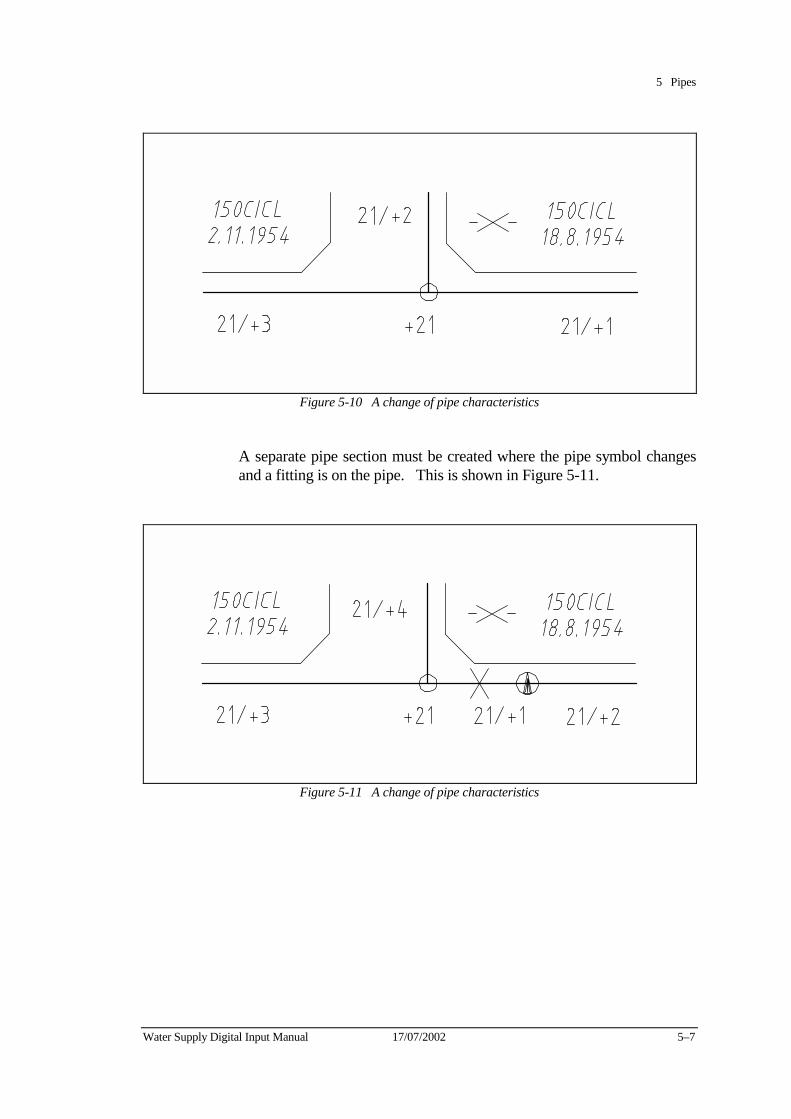
5 Pipes
Water Supply Digital Input Manual 17/07/2002 5–7
Figure 5-10 A change of pipe characteristics
A separate pipe section must be created where the pipe symbol changes and a fitting is on the pipe. This is shown in Figure 5-11.
Figure 5-11 A change of pipe characteristics
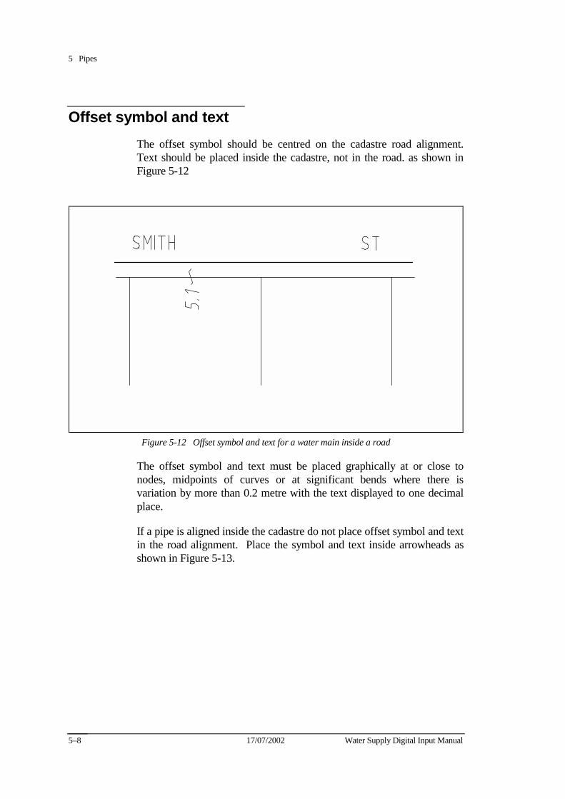
5 Pipes
17/07/2002 Water Supply Digital Input Manual 5–8
Offset symbol and text The offset symbol should be centred on the cadastre road alignment. Text should be placed inside the cadastre, not in the road. as shown in Figure 5-12
Figure 5-12 Offset symbol and text for a water main inside a road
The offset symbol and text must be placed graphically at or close to nodes, midpoints of curves or at significant bends where there is variation by more than 0.2 metre with the text displayed to one decimal place.
If a pipe is aligned inside the cadastre do not place offset symbol and text in the road alignment. Place the symbol and text inside arrowheads as shown in Figure 5-13.
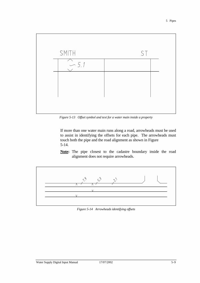
5 Pipes
Water Supply Digital Input Manual 17/07/2002 5–9
Figure 5-13 Offset symbol and text for a water main inside a property
If more than one water main runs along a road, arrowheads must be used to assist in identifying the offsets for each pipe. The arrowheads must touch both the pipe and the road alignment as shown in Figure 5-14.
Note: The pipe closest to the cadastre boundary inside the road alignment does not require arrowheads.
Figure 5-14 Arrowheads identifying offsets
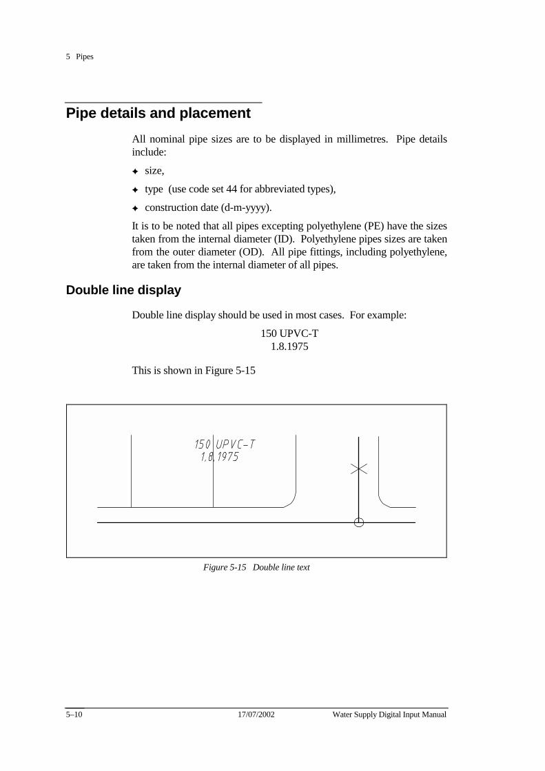
5 Pipes
17/07/2002 Water Supply Digital Input Manual 5–10
Pipe details and placement All nominal pipe sizes are to be displayed in millimetres. Pipe details include:
✦ size,
✦ type (use code set 44 for abbreviated types),
✦ construction date (d-m-yyyy).
It is to be noted that all pipes excepting polyethylene (PE) have the sizes taken from the internal diameter (ID). Polyethylene pipes sizes are taken from the outer diameter (OD). All pipe fittings, including polyethylene, are taken from the internal diameter of all pipes.
Double line display
Double line display should be used in most cases. For example:
150 UPVC-T 1.8.1975
This is shown in Figure 5-15
Figure 5-15 Double line text
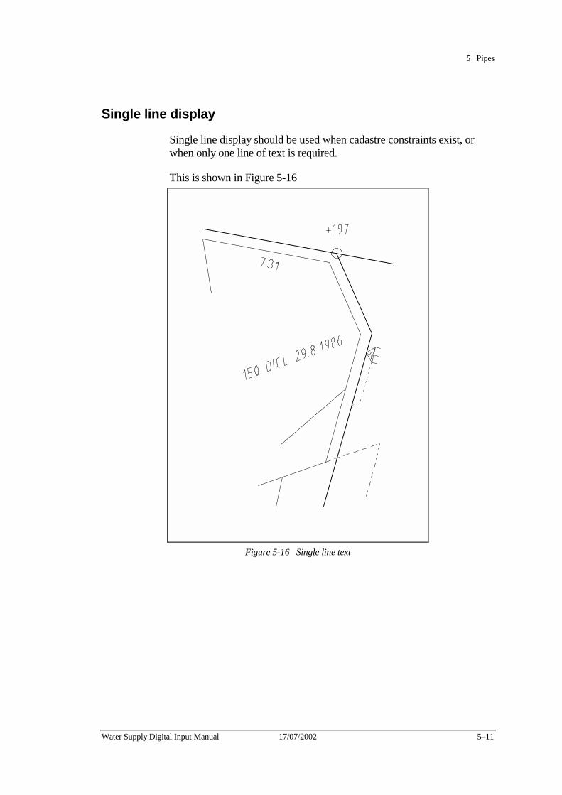
5 Pipes
Water Supply Digital Input Manual 17/07/2002 5–11
Single line display
Single line display should be used when cadastre constraints exist, or when only one line of text is required.
This is shown in Figure 5-16
Figure 5-16 Single line text
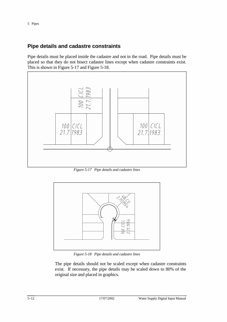
5 Pipes
17/07/2002 Water Supply Digital Input Manual 5–12
Pipe details and cadastre constraints
Pipe details must be placed inside the cadastre and not in the road. Pipe details must be placed so that they do not bisect cadastre lines except when cadastre constraints exist. This is shown in Figure 5-17 and Figure 5-18.
Figure 5-17 Pipe details and cadastre lines
Figure 5-18 Pipe details and cadastre lines
The pipe details should not be scaled except when cadastre constraints exist. If necessary, the pipe details may be scaled down to 80% of the original size and placed in graphics.
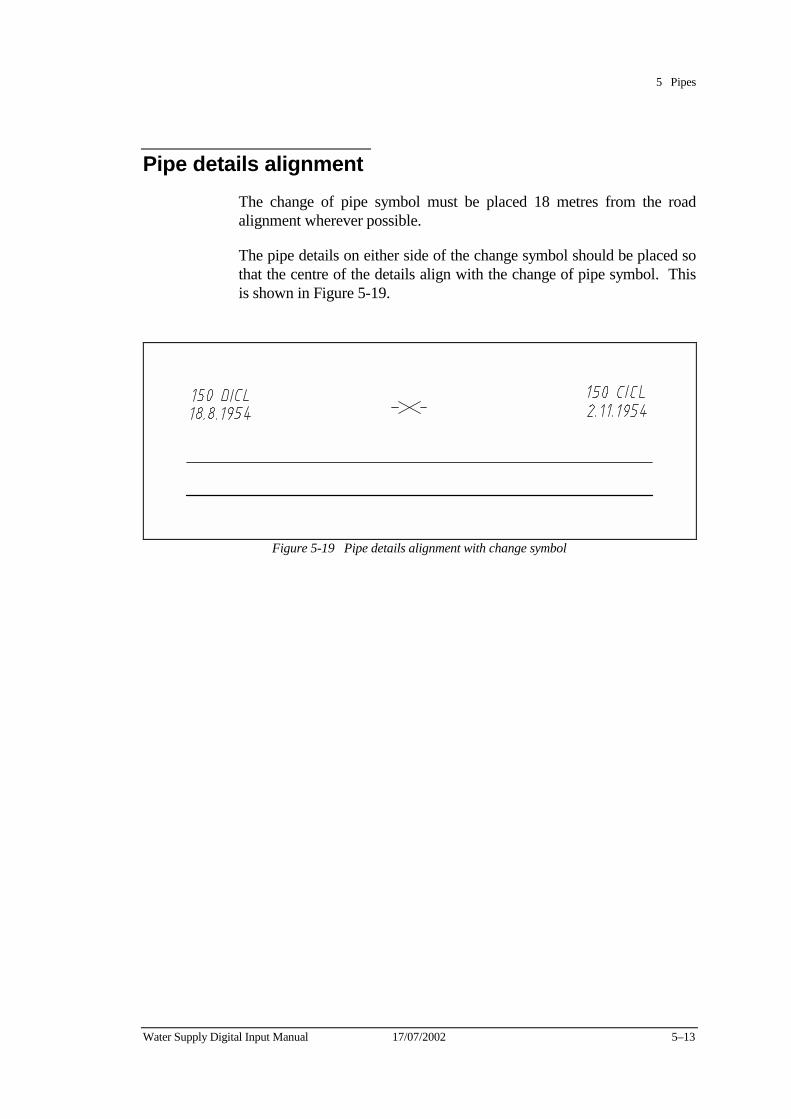
5 Pipes
Water Supply Digital Input Manual 17/07/2002 5–13
Pipe details alignment The change of pipe symbol must be placed 18 metres from the road alignment wherever possible.
The pipe details on either side of the change symbol should be placed so that the centre of the details align with the change of pipe symbol. This is shown in Figure 5-19.
Figure 5-19 Pipe details alignment with change symbol
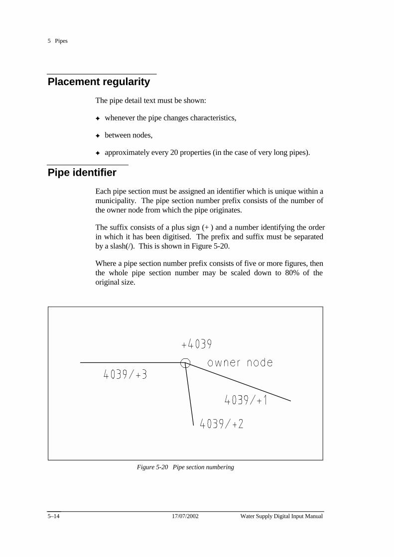
5 Pipes
17/07/2002 Water Supply Digital Input Manual 5–14
Placement regularity The pipe detail text must be shown:
✦ whenever the pipe changes characteristics,
✦ between nodes,
✦ approximately every 20 properties (in the case of very long pipes).
Pipe identifier Each pipe section must be assigned an identifier which is unique within a municipality. The pipe section number prefix consists of the number of the owner node from which the pipe originates.
The suffix consists of a plus sign (+) and a number identifying the order in which it has been digitised. The prefix and suffix must be separated by a slash(/). This is shown in Figure 5-20.
Where a pipe section number prefix consists of five or more figures, then the whole pipe section number may be scaled down to 80% of the original size.
Figure 5-20 Pipe section numbering
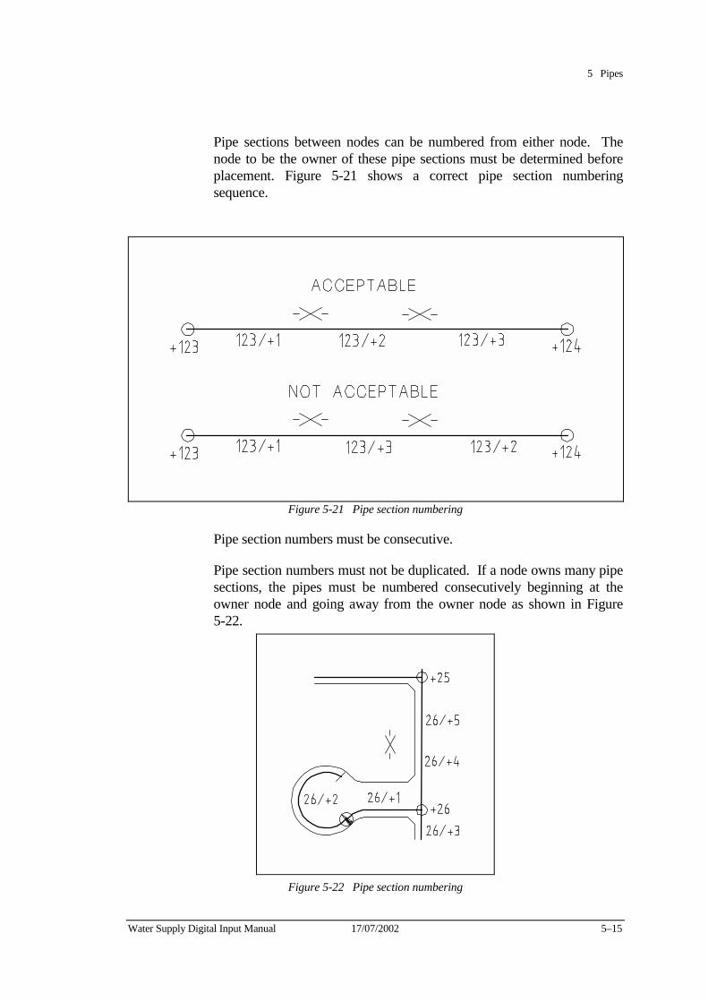
5 Pipes
Water Supply Digital Input Manual 17/07/2002 5–15
Pipe sections between nodes can be numbered from either node. The node to be the owner of these pipe sections must be determined before placement. Figure 5-21 shows a correct pipe section numbering sequence.
Figure 5-21 Pipe section numbering
Pipe section numbers must be consecutive.
Pipe section numbers must not be duplicated. If a node owns many pipe sections, the pipes must be numbered consecutively beginning at the owner node and going away from the owner node as shown in Figure 5-22.
Figure 5-22 Pipe section numbering

5 Pipes
17/07/2002 Water Supply Digital Input Manual 5–16
The first pipe in court bowls must be entered from the owner node. Figure 5-23 shows pipe section number sequences in a court bowl.
Figure 5-23 Pipe section numbers in a court bowl
Placement of pipe section numbers
Pipe section numbers should be placed at zero degrees, opposite the pipe details and within the road alignment, if possible. The numbers may be rotated to fit the road alignment if necessary. This is shown in Figure 5-24.
Figure 5-24 Pipe section number placement
Pipe section numbers should not be scaled, unless the prefix is five or more figures. Then it may be scaled down to 80%.
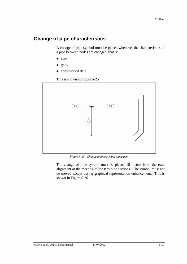
5 Pipes
Water Supply Digital Input Manual 17/07/2002 5–17
Change of pipe characteristics A change of pipe symbol must be placed whenever the characteristics of a pipe between nodes are changed, that is:
✦ size,
✦ type,
✦ construction date.
This is shown in Figure 5-25
Figure 5-25 Change of pipe symbol placement
The change of pipe symbol must be placed 18 metres from the road alignment at the meeting of the two pipe sections. The symbol must not be moved except during graphical representation enhancement. This is shown in Figure 5-26.
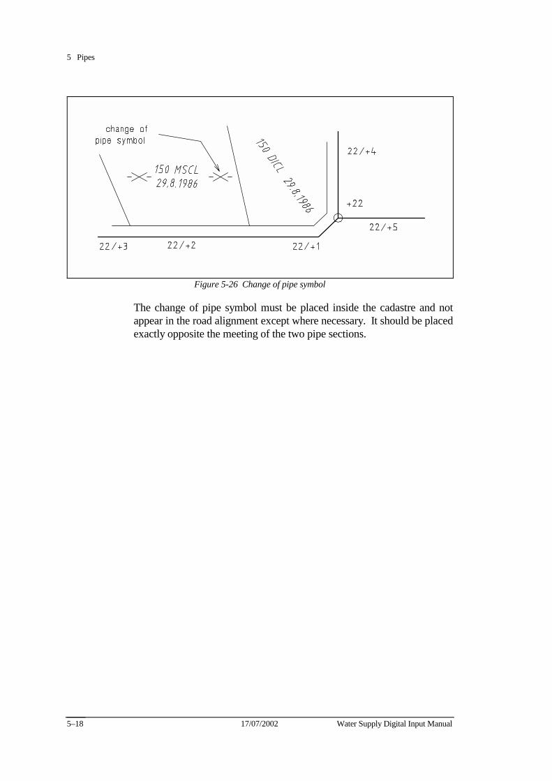
5 Pipes
17/07/2002 Water Supply Digital Input Manual 5–18
Figure 5-26 Change of pipe symbol
The change of pipe symbol must be placed inside the cadastre and not appear in the road alignment except where necessary. It should be placed exactly opposite the meeting of the two pipe sections.
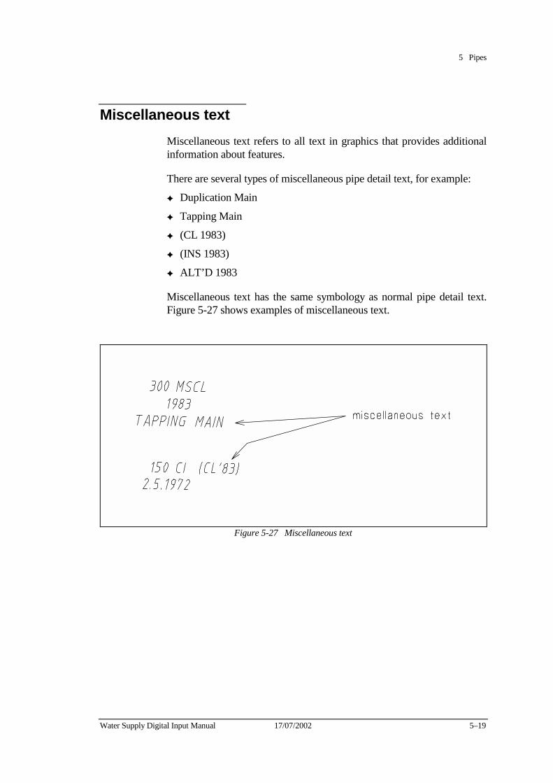
5 Pipes
Water Supply Digital Input Manual 17/07/2002 5–19
Miscellaneous text Miscellaneous text refers to all text in graphics that provides additional information about features.
There are several types of miscellaneous pipe detail text, for example:
✦ Duplication Main
✦ Tapping Main
✦ (CL 1983)
✦ (INS 1983)
✦ ALT’D 1983
Miscellaneous text has the same symbology as normal pipe detail text. Figure 5-27 shows examples of miscellaneous text.
Figure 5-27 Miscellaneous text
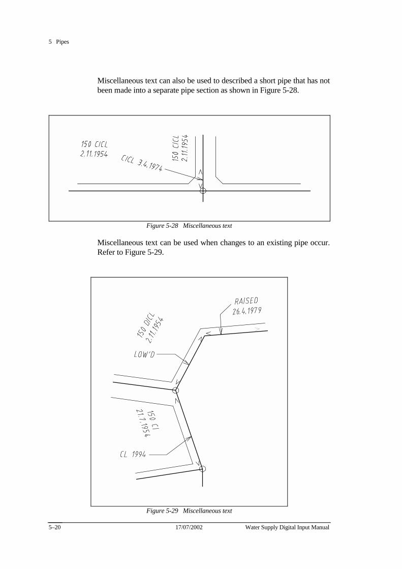
5 Pipes
17/07/2002 Water Supply Digital Input Manual 5–20
Miscellaneous text can also be used to described a short pipe that has not been made into a separate pipe section as shown in Figure 5-28.
Figure 5-28 Miscellaneous text
Miscellaneous text can be used when changes to an existing pipe occur. Refer to Figure 5-29.
Figure 5-29 Miscellaneous text
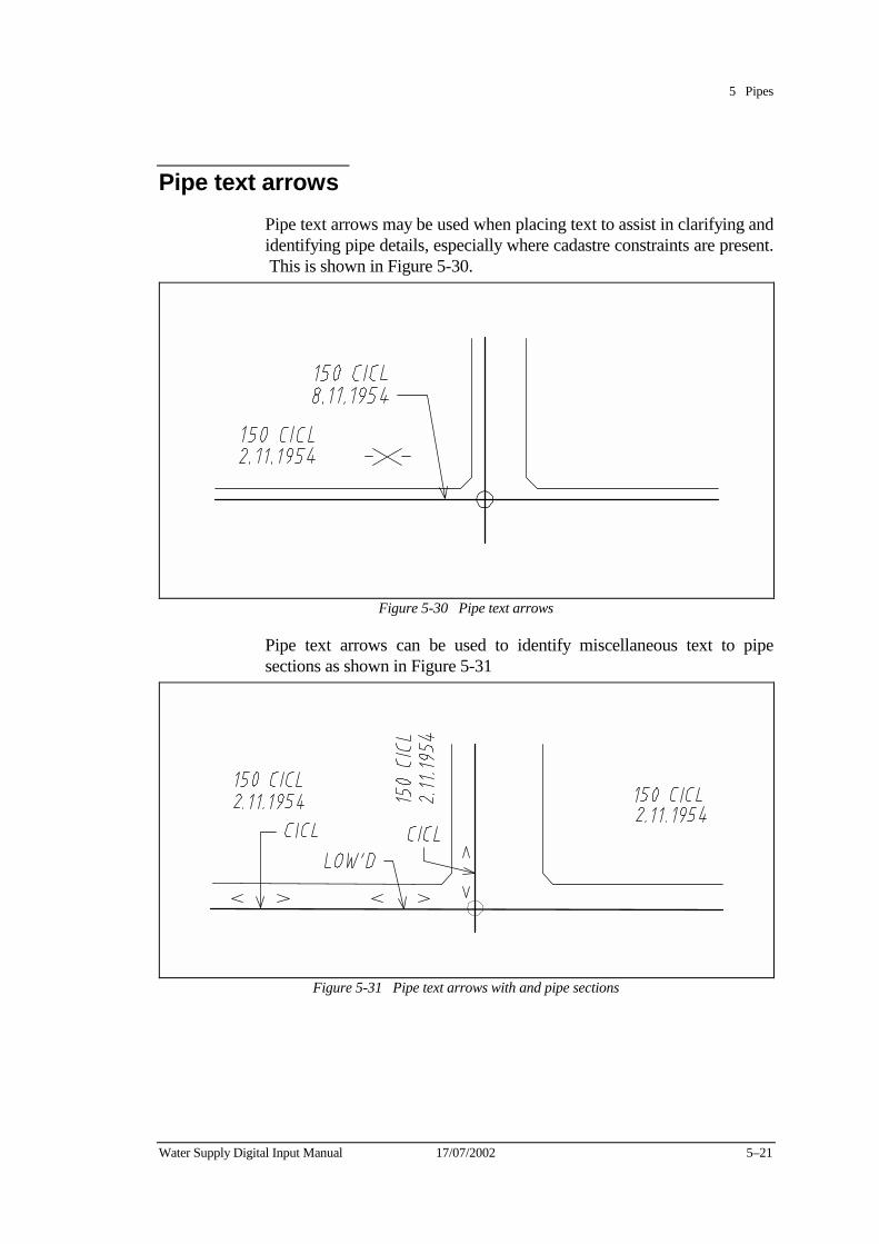
5 Pipes
Water Supply Digital Input Manual 17/07/2002 5–21
Pipe text arrows Pipe text arrows may be used when placing text to assist in clarifying and identifying pipe details, especially where cadastre constraints are present. This is shown in Figure 5-30.
Figure 5-30 Pipe text arrows
Pipe text arrows can be used to identify miscellaneous text to pipe sections as shown in Figure 5-31
Figure 5-31 Pipe text arrows with and pipe sections
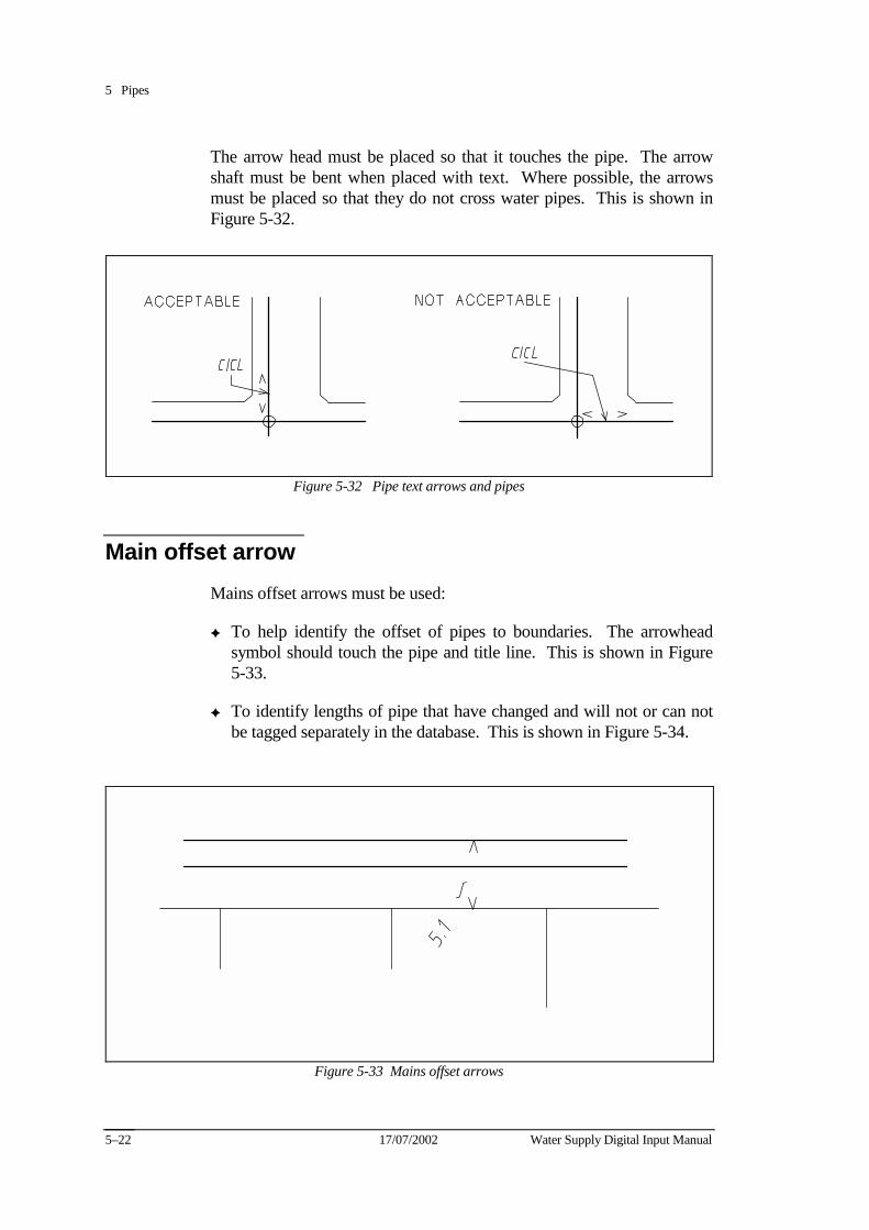
5 Pipes
17/07/2002 Water Supply Digital Input Manual 5–22
The arrow head must be placed so that it touches the pipe. The arrow shaft must be bent when placed with text. Where possible, the arrows must be placed so that they do not cross water pipes. This is shown in Figure 5-32.
Figure 5-32 Pipe text arrows and pipes
Main offset arrow Mains offset arrows must be used:
✦ To help identify the offset of pipes to boundaries. The arrowhead symbol should touch the pipe and title line. This is shown in Figure 5-33.
✦ To identify lengths of pipe that have changed and will not or can not be tagged separately in the database. This is shown in Figure 5-34.
Figure 5-33 Mains offset arrows
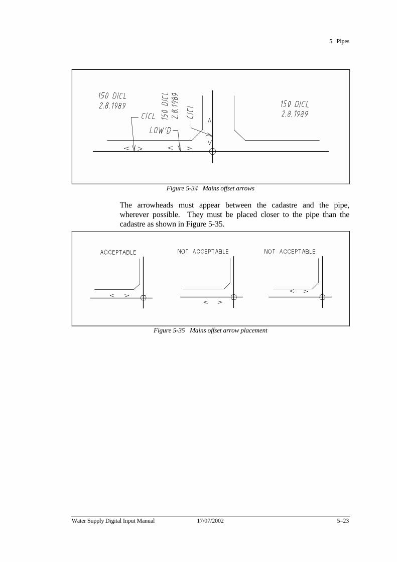
5 Pipes
Water Supply Digital Input Manual 17/07/2002 5–23
Figure 5-34 Mains offset arrows
The arrowheads must appear between the cadastre and the pipe, wherever possible. They must be placed closer to the pipe than the cadastre as shown in Figure 5-35.
Figure 5-35 Mains offset arrow placement
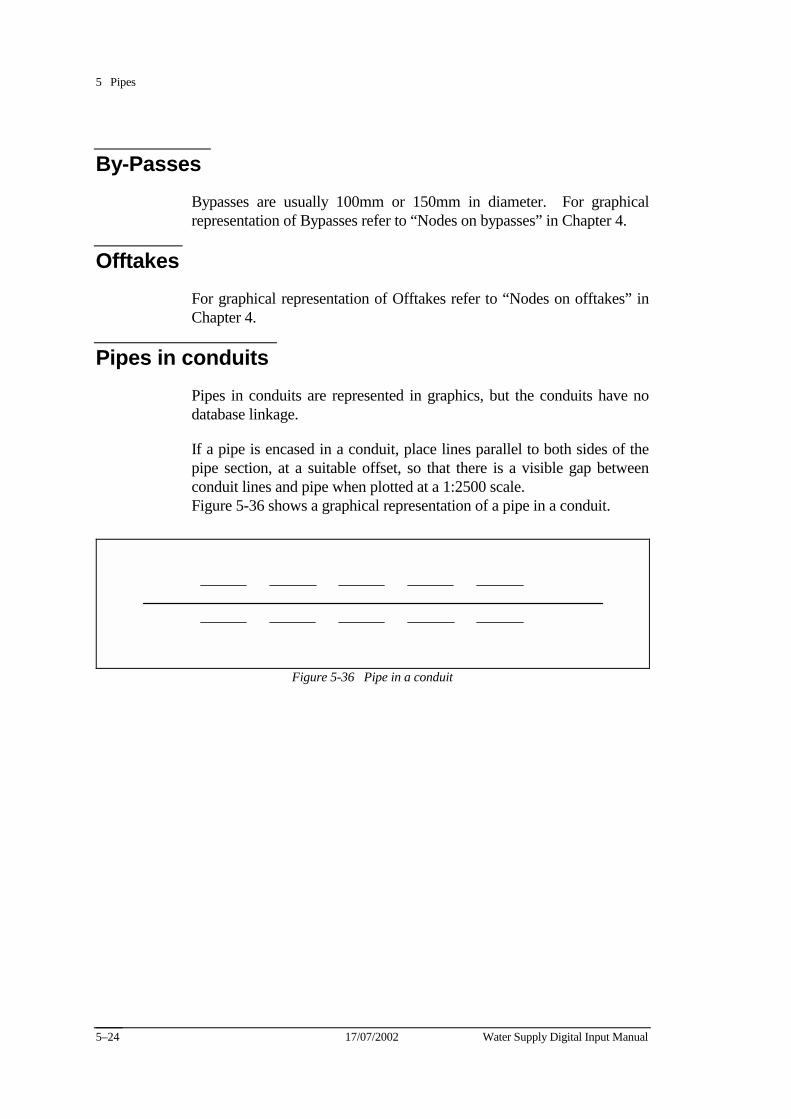
5 Pipes
17/07/2002 Water Supply Digital Input Manual 5–24
By-Passes Bypasses are usually 100mm or 150mm in diameter. For graphical representation of Bypasses refer to “Nodes on bypasses” in Chapter 4.
Offtakes For graphical representation of Offtakes refer to “Nodes on offtakes” in Chapter 4.
Pipes in conduits Pipes in conduits are represented in graphics, but the conduits have no database linkage.
If a pipe is encased in a conduit, place lines parallel to both sides of the pipe section, at a suitable offset, so that there is a visible gap between conduit lines and pipe when plotted at a 1:2500 scale. Figure 5-36 shows a graphical representation of a pipe in a conduit.
Figure 5-36 Pipe in a conduit
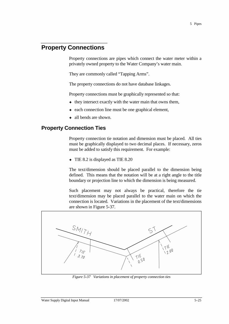
5 Pipes
Water Supply Digital Input Manual 17/07/2002 5–25
Property Connections Property connections are pipes which connect the water meter within a privately owned property to the Water Company’s water main.
They are commonly called “Tapping Arms”.
The property connections do not have database linkages.
Property connections must be graphically represented so that:
✦ they intersect exactly with the water main that owns them,
✦ each connection line must be one graphical element,
✦ all bends are shown.
Property Connection Ties
Property connection tie notation and dimension must be placed. All ties must be graphically displayed to two decimal places. If necessary, zeros must be added to satisfy this requirement. For example:
✦ TIE 8.2 is displayed as TIE 8.20
The text/dimension should be placed parallel to the dimension being defined. This means that the notation will be at a right angle to the title boundary or projection line to which the dimension is being measured.
Such placement may not always be practical, therefore the tie text/dimension may be placed parallel to the water main on which the connection is located. Variations in the placement of the text/dimensions are shown in Figure 5-37.
Figure 5-37 Variations in placement of property connection ties
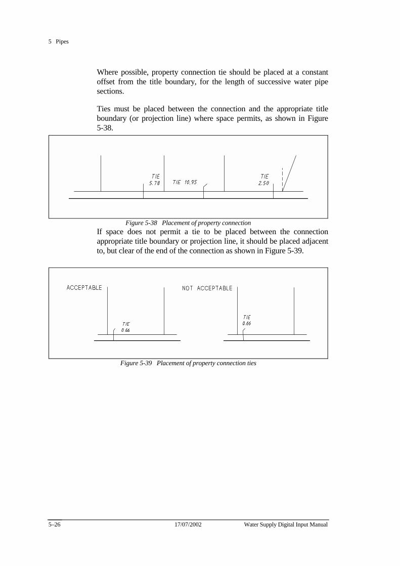
5 Pipes
17/07/2002 Water Supply Digital Input Manual 5–26
Where possible, property connection tie should be placed at a constant offset from the title boundary, for the length of successive water pipe sections.
Ties must be placed between the connection and the appropriate title boundary (or projection line) where space permits, as shown in Figure 5-38.
Figure 5-38 Placement of property connection If space does not permit a tie to be placed between the connection appropriate title boundary or projection line, it should be placed adjacent to, but clear of the end of the connection as shown in Figure 5-39.
Figure 5-39 Placement of property connection ties
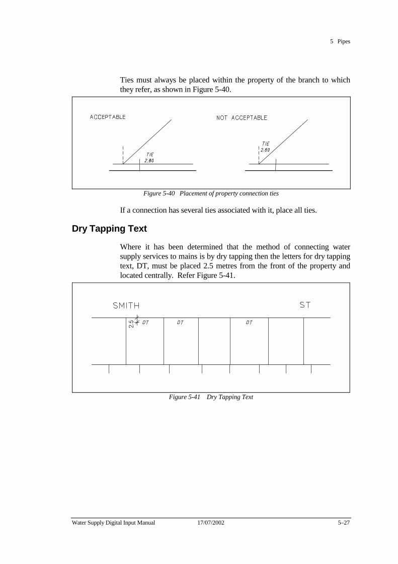
5 Pipes
Water Supply Digital Input Manual 17/07/2002 5–27
Ties must always be placed within the property of the branch to which they refer, as shown in Figure 5-40.
Figure 5-40 Placement of property connection ties
If a connection has several ties associated with it, place all ties.
Dry Tapping Text
Where it has been determined that the method of connecting water supply services to mains is by dry tapping then the letters for dry tapping text, DT, must be placed 2.5 metres from the front of the property and located centrally. Refer Figure 5-41.
Figure 5-41 Dry Tapping Text
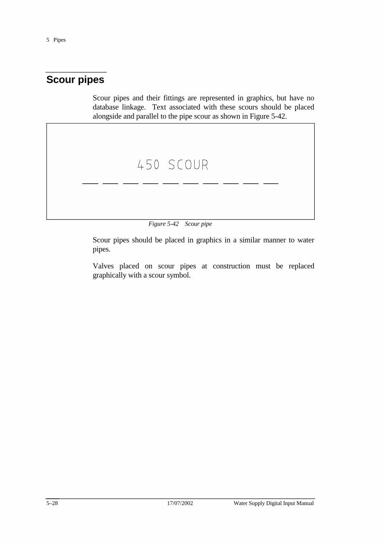
5 Pipes
17/07/2002 Water Supply Digital Input Manual 5–28
Scour pipes Scour pipes and their fittings are represented in graphics, but have no database linkage. Text associated with these scours should be placed alongside and parallel to the pipe scour as shown in Figure 5-42.
Figure 5-42 Scour pipe
Scour pipes should be placed in graphics in a similar manner to water pipes.
Valves placed on scour pipes at construction must be replaced graphically with a scour symbol.
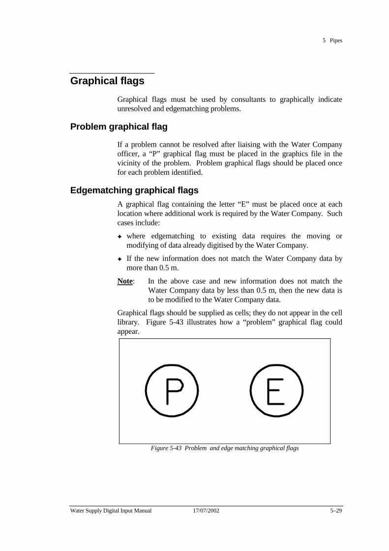
5 Pipes
Water Supply Digital Input Manual 17/07/2002 5–29
Graphical flags Graphical flags must be used by consultants to graphically indicate unresolved and edgematching problems.
Problem graphical flag
If a problem cannot be resolved after liaising with the Water Company officer, a “P” graphical flag must be placed in the graphics file in the vicinity of the problem. Problem graphical flags should be placed once for each problem identified.
Edgematching graphical flags A graphical flag containing the letter “E” must be placed once at each location where additional work is required by the Water Company. Such cases include:
✦ where edgematching to existing data requires the moving or modifying of data already digitised by the Water Company.
✦ If the new information does not match the Water Company data by more than 0.5 m.
Note: In the above case and new information does not match the Water Company data by less than 0.5 m, then the new data is to be modified to the Water Company data.
Graphical flags should be supplied as cells; they do not appear in the cell library. Figure 5-43 illustrates how a “problem” graphical flag could appear.
Figure 5-43 Problem and edge matching graphical flags
5 Pipes
17/07/2002 Water Supply Digital Input Manual 5–30
Documentation to be supplied
Consultants must supply information to the Water Company about each flag placed detailing:
✦ Municipality name,
✦ The graphical file number,
✦ Approximate AMG co-ordinates,
✦ A clear, accurate and precise description of the problem,
✦ Numbered attachments (for example, copies of field notes and/or plans to clarify the nature of the problem)
Other authority’s water mains For each pipe section that does not belong to the Water Company:
✦ Do not input pipes, fittings or associated text
✦ Documentation is to be forwarded to the Water Company relating to the details of these mains and their location.
✦ Place the following label -
OTHER AUTHORITY WATER MAIN
either along the alignment of the main pipe or across the general area covered by the mains.
If the other authority mains connect to one of the Water Company’s pipe sections, place a node at the intersection.
Abandoned Water Mains Where it has been determined that water pipes, etc. have been abandoned, the consultant must supply to the Water Company a hard copy plan detailing the extent of abandonment.
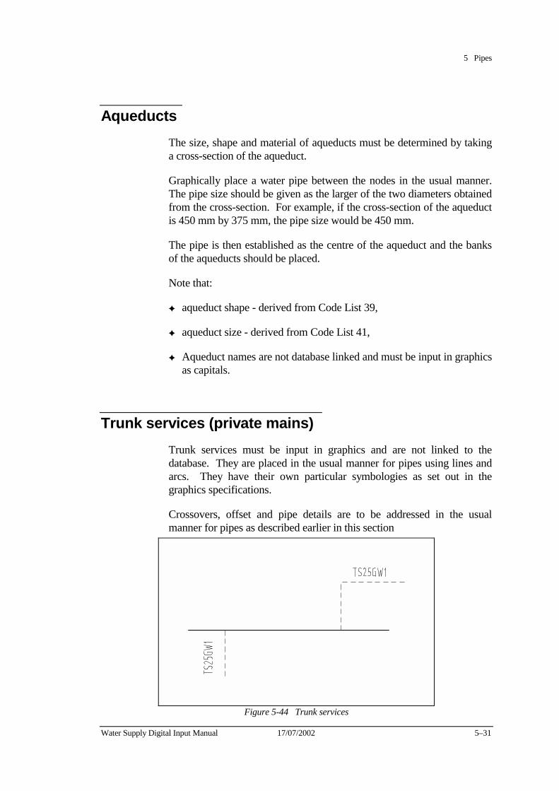
5 Pipes
Water Supply Digital Input Manual 17/07/2002 5–31
Aqueducts The size, shape and material of aqueducts must be determined by taking a cross-section of the aqueduct.
Graphically place a water pipe between the nodes in the usual manner. The pipe size should be given as the larger of the two diameters obtained from the cross-section. For example, if the cross-section of the aqueduct is 450 mm by 375 mm, the pipe size would be 450 mm.
The pipe is then established as the centre of the aqueduct and the banks of the aqueducts should be placed.
Note that:
✦ aqueduct shape - derived from Code List 39,
✦ aqueduct size - derived from Code List 41,
✦ Aqueduct names are not database linked and must be input in graphics as capitals.
Trunk services (private mains) Trunk services must be input in graphics and are not linked to the database. They are placed in the usual manner for pipes using lines and arcs. They have their own particular symbologies as set out in the graphics specifications.
Crossovers, offset and pipe details are to be addressed in the usual manner for pipes as described earlier in this section
Figure 5-44 Trunk services
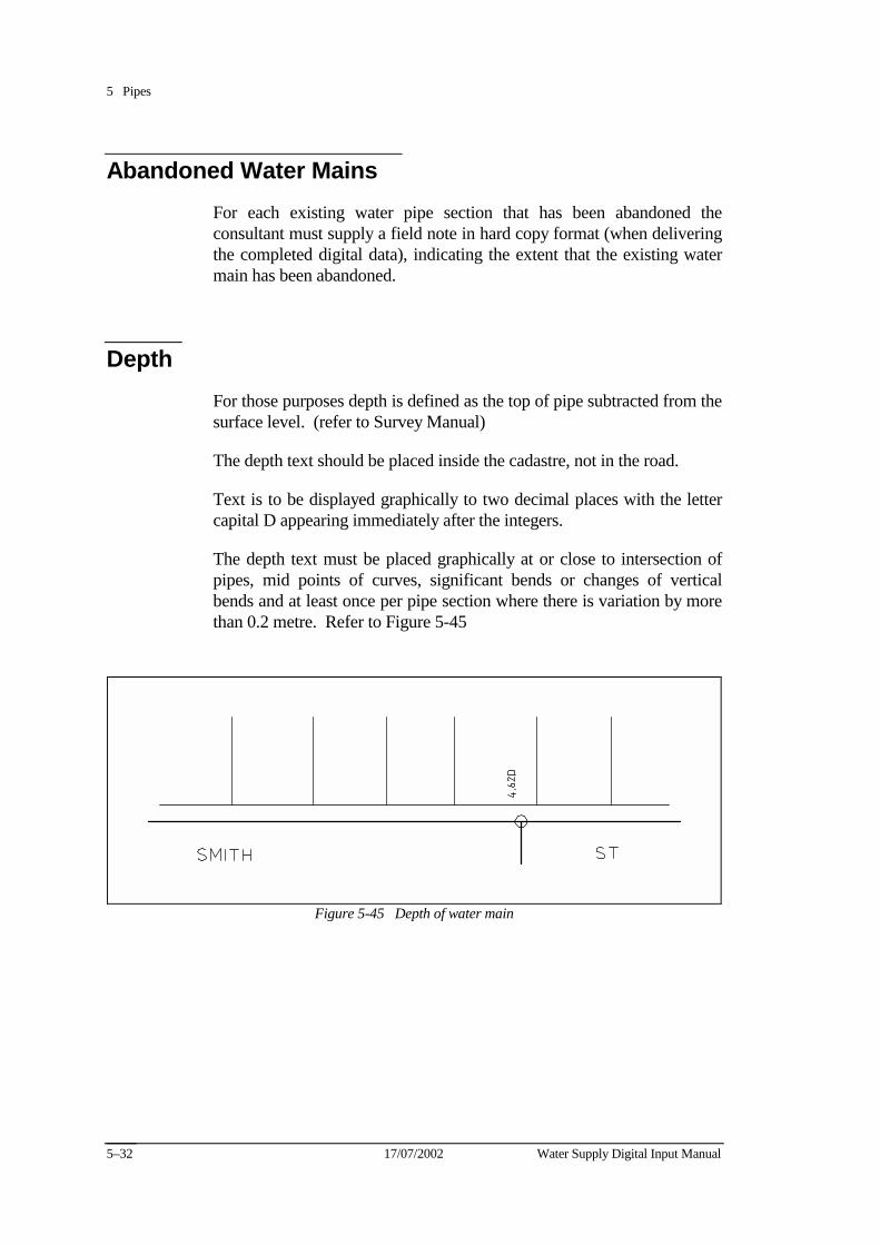
5 Pipes
17/07/2002 Water Supply Digital Input Manual 5–32
Abandoned Water Mains For each existing water pipe section that has been abandoned the consultant must supply a field note in hard copy format (when delivering the completed digital data), indicating the extent that the existing water main has been abandoned.
Depth For those purposes depth is defined as the top of pipe subtracted from the surface level. (refer to Survey Manual)
The depth text should be placed inside the cadastre, not in the road.
Text is to be displayed graphically to two decimal places with the letter capital D appearing immediately after the integers.
The depth text must be placed graphically at or close to intersection of pipes, mid points of curves, significant bends or changes of vertical bends and at least once per pipe section where there is variation by more than 0.2 metre. Refer to Figure 5-45
Figure 5-45 Depth of water main
Water Supply Digital Input Manual 17/07/2002 6–1
Chapter 6 Valves This chapter describes the requirement for the graphical entry of valves.
The valve symbols do have a database linkage whereas the numbers do not.
Valves sizes are the same as the internal pipe size.
Valves fall into the following categories unless otherwise determined:
✦ Valves that are sized between 80 mm and 450 mm inclusive are sluice valves,
✦ Valves that are greater than 450 mm are butterfly valves,
✦ Valves on pipes less than 80 mm are gate valves.
Air Valves There are three types of air valves:
✦ Type A rises above the ground from the side of the main,
✦ Type B is used in roads and is flush with the road surface,
✦ Type AB rises above the ground from the top of the main.
Ferrules Ferrules must be placed as ferrules and numbered as valves. Ferrules are assumed to be less than 80 mm diameter.

6 Valves
17/07/2002 Water Supply Digital Input Manual 6–2
Shut valves Shut valves are determined by the Water Company and relate to valves that isolate water supply distribution zones.
The shut valve symbol is only to be placed by the Water Company.
Valves and ferrules at the end of mains and in courts should be considered shut for database entry, however, they do not have the circle placed over the valves symbol. The corresponding entry in the database for that particular valve should show that valve as 100% shut (code list entry = 6).
Other valves Other types of valves including reflux, needle, altitude and pressure valves are less common but must be addressed in the same manner using the relevant cell and entry from the code lists.
Valve number These numbers are to be supplied, upon request, by the Water Company. Valve numbers must be unique within each municipality, but do not have to be sequential. All text associated with valves must have the same symbology and be placed on the same level as the valve number.
Five figure valve numbers should be scaled down to 80% of the original size.
Valve numbers should be placed at an angle of 45 degrees, as shown in Figure 6-1. Numbers should be placed in the road alignment wherever possible.
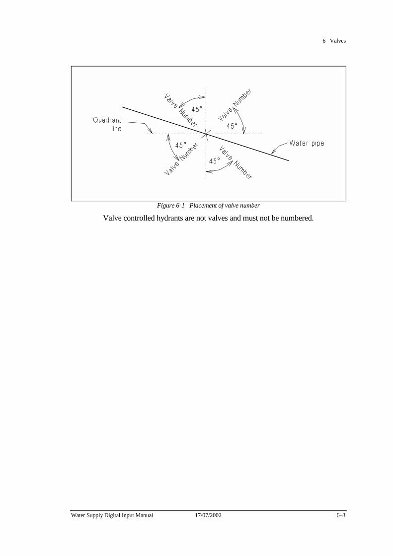
6 Valves
Water Supply Digital Input Manual 17/07/2002 6–3
Figure 6-1 Placement of valve number
Valve controlled hydrants are not valves and must not be numbered.
6 Valves
17/07/2002 Water Supply Digital Input Manual 6–4
Valve placement The following rules apply when placing valves:
✦ Valves must be placed in graphics in the position as determined by field survey,
✦ If a valve is between two reducers and the distance is less than a standard road width then:-
the valve must be entered on the same level as the pipe on which it is placed,
✦ If a valve is between a reducer and a node and the distance between the node and the reducer is less than three metres then:-
the valve must be entered on the same level as the pipe on which it is placed,
✦ If a water main is insulated, the valve is assumed not to be insulated, unless otherwise determined.
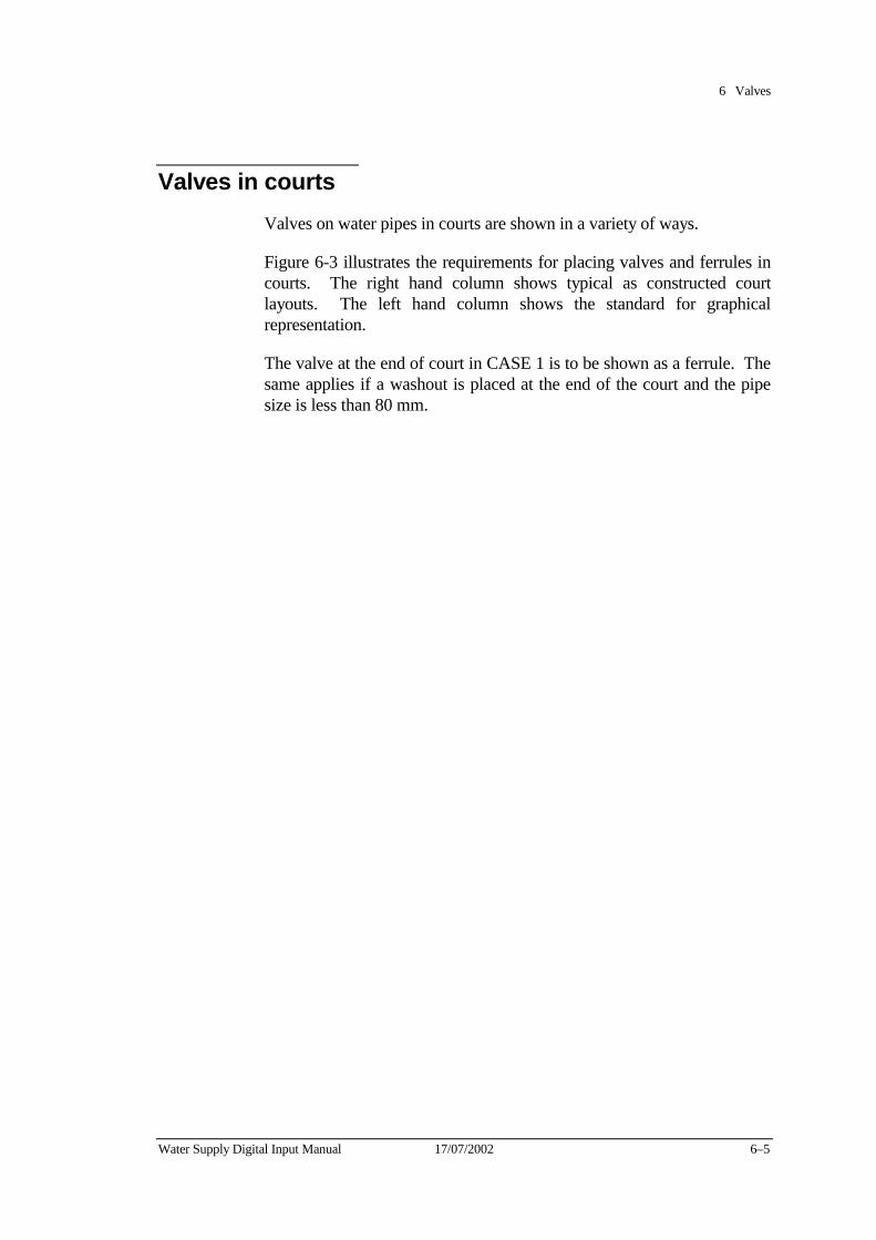
6 Valves
Water Supply Digital Input Manual 17/07/2002 6–5
Valves in courts Valves on water pipes in courts are shown in a variety of ways.
Figure 6-3 illustrates the requirements for placing valves and ferrules in courts. The right hand column shows typical as constructed court layouts. The left hand column shows the standard for graphical representation.
The valve at the end of court in CASE 1 is to be shown as a ferrule. The same applies if a washout is placed at the end of the court and the pipe size is less than 80 mm.
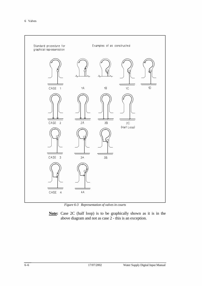
6 Valves
17/07/2002 Water Supply Digital Input Manual 6–6
Figure 6-3 Representation of valves in courts
Note: Case 2C (half loop) is to be graphically shown as it is in the above diagram and not as case 2 - this is an exception.
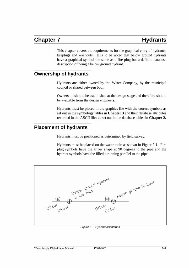
Water Supply Digital Input Manual 17/07/2002 7–1
Chapter 7 Hydrants This chapter covers the requirements for the graphical entry of hydrants, fireplugs and washouts. It is to be noted that below ground hydrants have a graphical symbol the same as a fire plug but a definite database description of being a below ground hydrant.
Ownership of hydrants Hydrants are either owned by the Water Company, by the municipal council or shared between both.
Ownership should be established at the design stage and therefore should be available from the design engineers.
Hydrants must be placed in the graphics file with the correct symbols as set out in the symbology tables in Chapter 3 and their database attributes recorded in the ASCII files as set out in the database tables in Chapter 2.
Placement of hydrants Hydrants must be positioned as determined by field survey.
Hydrants must be placed on the water main as shown in Figure 7-1. Fire plug symbols have the arrow shape at 90 degrees to the pipe and the hydrant symbols have the filled x running parallel to the pipe.
Figure 7-1 Hydrant orientation
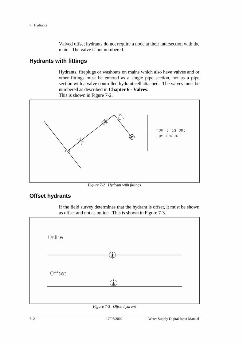
7 Hydrants
17/07/2002 Water Supply Digital Input Manual 7–2
Valved offset hydrants do not require a node at their intersection with the main. The valve is not numbered.
Hydrants with fittings
Hydrants, fireplugs or washouts on mains which also have valves and or other fittings must be entered as a single pipe section, not as a pipe section with a valve controlled hydrant cell attached. The valves must be numbered as described in Chapter 6 - Valves. This is shown in Figure 7-2.
Figure 7-2 Hydrant with fittings
Offset hydrants
If the field survey determines that the hydrant is offset, it must be shown as offset and not as online. This is shown in Figure 7-3.
Figure 7-3 Offset hydrant
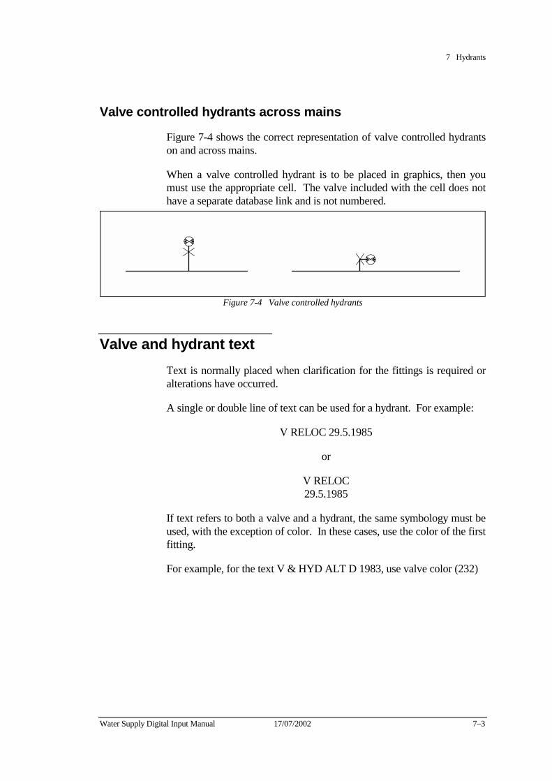
7 Hydrants
Water Supply Digital Input Manual 17/07/2002 7–3
Valve controlled hydrants across mains
Figure 7-4 shows the correct representation of valve controlled hydrants on and across mains.
When a valve controlled hydrant is to be placed in graphics, then you must use the appropriate cell. The valve included with the cell does not have a separate database link and is not numbered.
Figure 7-4 Valve controlled hydrants
Valve and hydrant text Text is normally placed when clarification for the fittings is required or alterations have occurred.
A single or double line of text can be used for a hydrant. For example:
V RELOC 29.5.1985
or
V RELOC 29.5.1985
If text refers to both a valve and a hydrant, the same symbology must be used, with the exception of color. In these cases, use the color of the first fitting.
For example, for the text V & HYD ALT D 1983, use valve color (232)
7 Hydrants
17/07/2002 Water Supply Digital Input Manual 7–4
Fireplug and washout symbol A fire plug usually occurs between the ends of a pipe, while a washout occurs at the end of a pipe.
A washout is placed at the end of a main to enable the Water Company to flush the main.
The cell library does not include a cell for a washout. If a washout located on a pipe of less than 80 mm a ferrule is to be placed (closed status). If a washout is located on a pipe 80 mm or greater a fireplug is to be placed. The database must indicate a washout.
If the fire plug is owned by a council it must be placed as a fireplug in the database and not as a washout.
Below Ground hydrants As from 1st January 1992, the Water Company implemented the change from above to below ground hydrants.
For graphical representation purposes, this hydrant is shown as a fireplug symbol.
There is a database value to differentiate between above or below ground hydrants and this must be recorded in the ASCII database file. Refer to Code Set 206.
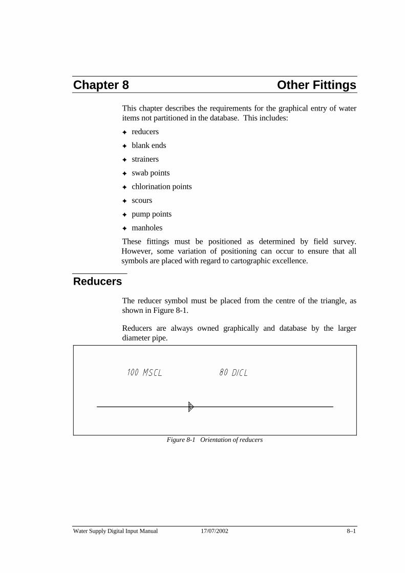
Water Supply Digital Input Manual 17/07/2002 8–1
Chapter 8 Other Fittings This chapter describes the requirements for the graphical entry of water items not partitioned in the database. This includes:
✦ reducers
✦ blank ends
✦ strainers
✦ swab points
✦ chlorination points
✦ scours
✦ pump points
✦ manholes
These fittings must be positioned as determined by field survey. However, some variation of positioning can occur to ensure that all symbols are placed with regard to cartographic excellence.
Reducers The reducer symbol must be placed from the centre of the triangle, as shown in Figure 8-1.
Reducers are always owned graphically and database by the larger diameter pipe.
Figure 8-1 Orientation of reducers
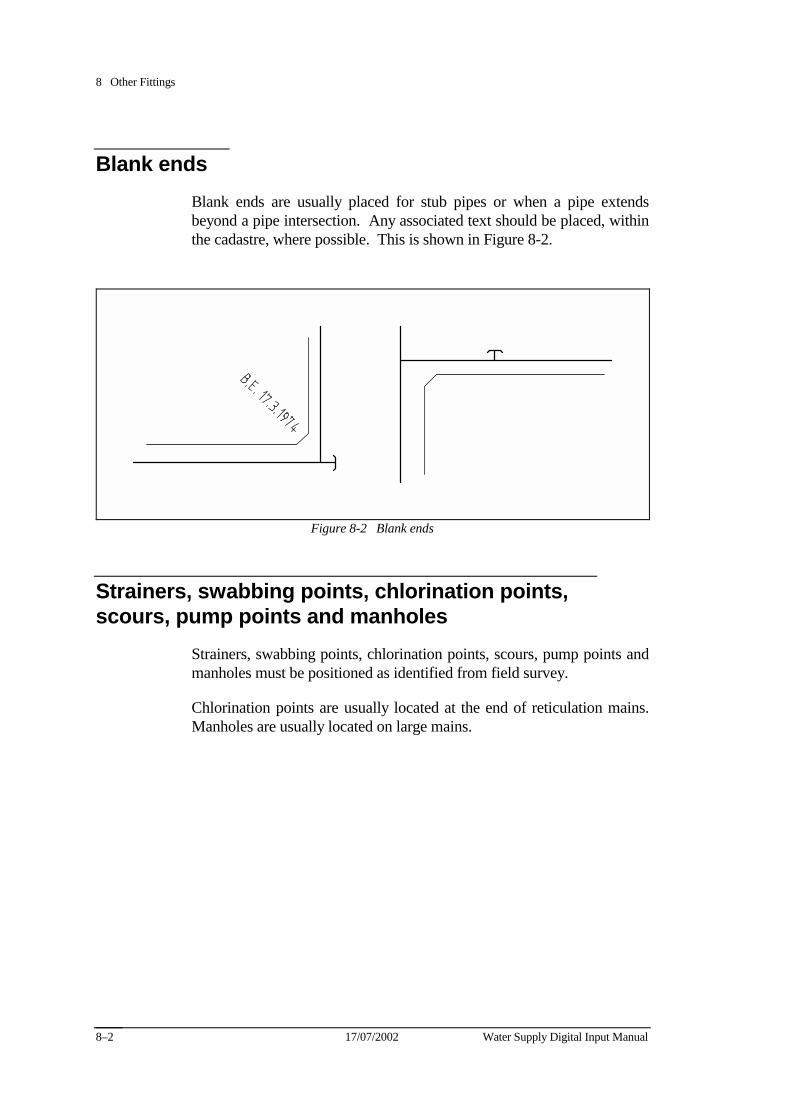
8 Other Fittings
17/07/2002 Water Supply Digital Input Manual 8–2
Blank ends Blank ends are usually placed for stub pipes or when a pipe extends beyond a pipe intersection. Any associated text should be placed, within the cadastre, where possible. This is shown in Figure 8-2.
Figure 8-2 Blank ends
Strainers, swabbing points, chlorination points, scours, pump points and manholes
Strainers, swabbing points, chlorination points, scours, pump points and manholes must be positioned as identified from field survey.
Chlorination points are usually located at the end of reticulation mains. Manholes are usually located on large mains.
Water Supply Digital Input Manual 17/07/2002 9–1
Chapter 9 Glossary of Terms
attribute
A database field (column) under which details are stored about a particular entity. An attribute could be seen as information about an entity (e.g. Material, size, etc.)
blank end
A short pipe with a welded blank plate attached to a water main which allows for future extensions.
block
A combination of elements which form a standard DXF graphical symbol for the representation of a feature. Blocks are able to be manipulated as a single element. These are the same as cells.
cell
A combination of elements which form a standard MicroStation graphical symbol for the representation of a feature. Cells are able to be manipulated as a single element.
code list
A list of numbered item descriptions which describe particular attribute values in standard terminology. Code list entry numbers record water supply item attributes in a relational database.
database file
An ASCII format file containing the database records of the attributes.
database schedule
A listing of all entities and associated attributes for which the Water Company requires valid database records. The schedule includes details of formats, default values and user notes for each attribute.
default value
A database entry to be input when a value cannot be determined.
9 Glossary of Terms
17/07/2002 Water Supply Digital Input Manual 9–2
edgematching
The process of joining new graphical information with that of the Water Company’s existing graphical data.
electrolysis point
Features on the water supply system which prevent corrosion by stray electric currents generated by the movement of water through the main.
element
An individual graphical item. For example, a line, circle or arc.
entity
A database table consisting of attributes (columns) and occurrences (rows). An entity is an object (eg. pipe, valve, node, etc.)
ferrule
A fitting placed where a service connection draws water from a reticulation water main.
fire plug
A fitting on the water supply system to allow the fire department access to the system or for flushing the water main.
FIS
“Facilities Information System”. This is the name given to the Water Company’s computer system which stores their assets in graphical and database form.
graphic file
Microstation .DGN or .DXF format file containing the digital water supply data.
hydrant
A fitting on the water supply system to allow the fire department access to the system or for flushing the water main.

9 Glossary of Terms
Water Supply Digital Input Manual 17/07/2002 9–3
level structure
A listing of the 63 MicroStation levels to which all items must be assigned in graphics files.
manhole
A fitting on large water mains that allows access to or inspection of the water main.
municipal index file
Graphics file showing the geographic division of and numbering of municipalities. The boundary lines define the placement of graphics data in each digital file.
node
Conveniently placed points used to break up the water pipe system into pipe sections. Nodes are not a physical feature of the water supply system - they exist in the graphics and database only.
occurrence
A database field (row) which records an entities attribute.
pipe id
The section number of a water pipe.
reducer
A fitting used to connect pipes of varying diameters with the minimum loss of pressure.
water pipe section
A length of water pipe between two nodes.
symbol
See cell or block.
9 Glossary of Terms
17/07/2002 Water Supply Digital Input Manual 9–4
symbology
The specification describing the way in which elements must appear in the graphic design files. Symbology defines the element class, element type, level, color, weight, line style, text criteria (font, height, width, justification) and cell requirements for each graphics item.
valve
A fitting on a water main that controls the rate and direction of water flow. Also used to isolate water mains for repair.

Appendices

Water Supply Digital Input Manual 17/07/2002 A–1
Appendix A
Supply of Digital Information form (blank)
See next page

Appendix A
Water Supply Digital Input Manual 17/07/2002 A–2
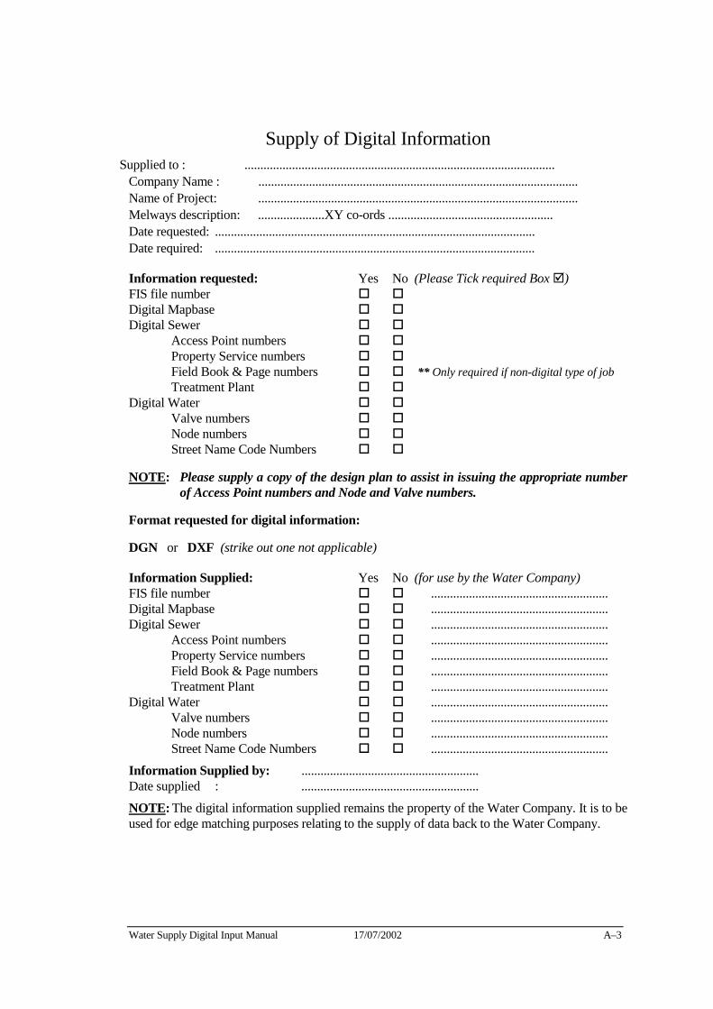
Water Supply Digital Input Manual 17/07/2002 A–3
Supply of Digital Information Supplied to : ..................................................................................................
Company Name : ..................................................................................................... Name of Project: ..................................................................................................... Melways description: .....................XY co-ords .................................................... Date requested: ..................................................................................................... Date required: .....................................................................................................
Information requested: Yes No (Please Tick required Box !) FIS file number " " Digital Mapbase " " Digital Sewer " " Access Point numbers " " Property Service numbers " " Field Book & Page numbers " " ** Only required if non-digital type of job Treatment Plant " " Digital Water " " Valve numbers " " Node numbers " " Street Name Code Numbers " "
NOTE: Please supply a copy of the design plan to assist in issuing the appropriate number of Access Point numbers and Node and Valve numbers.
Format requested for digital information:
DGN or DXF (strike out one not applicable)
Information Supplied: Yes No (for use by the Water Company) FIS file number " " ........................................................ Digital Mapbase " " ........................................................ Digital Sewer " " ........................................................ Access Point numbers " " ........................................................ Property Service numbers " " ........................................................ Field Book & Page numbers " " ........................................................ Treatment Plant " " ........................................................ Digital Water " " ........................................................ Valve numbers " " ........................................................ Node numbers " " ........................................................ Street Name Code Numbers " " ........................................................
Information Supplied by: ........................................................ Date supplied : ........................................................
NOTE: The digital information supplied remains the property of the Water Company. It is to be used for edge matching purposes relating to the supply of data back to the Water Company.

A–4 17/07/2002 Water Supply Digital Input Manual
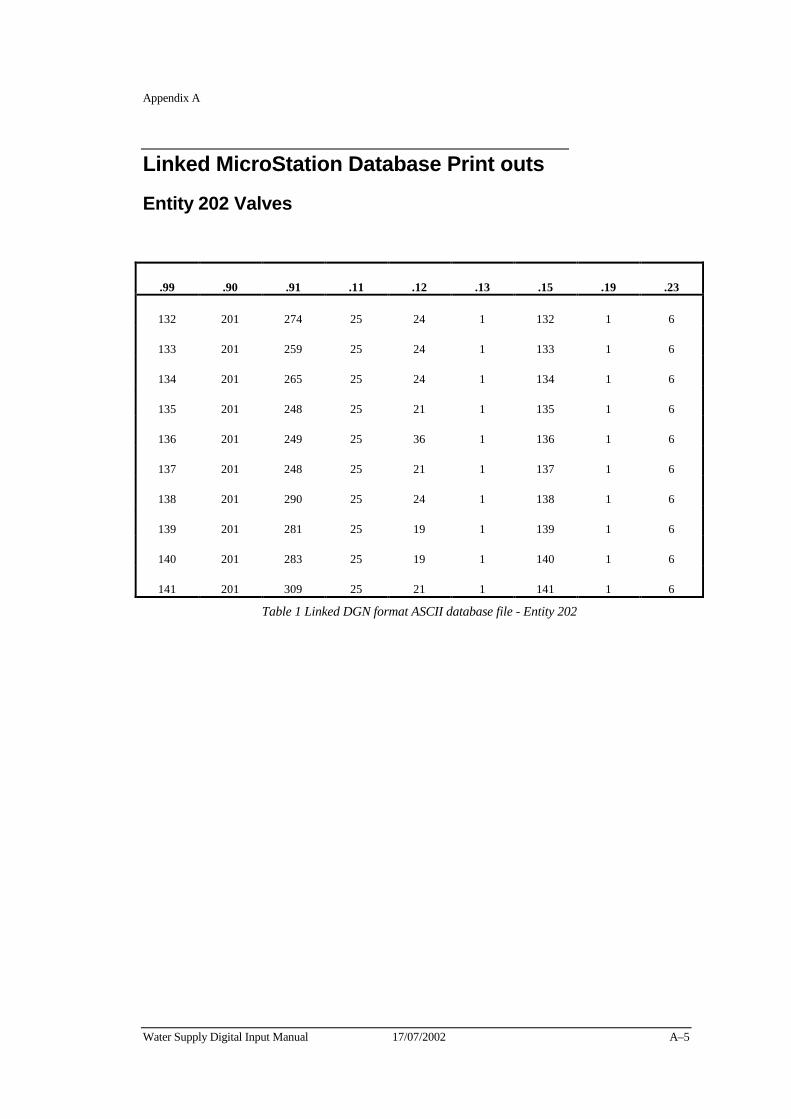
Appendix A
Water Supply Digital Input Manual 17/07/2002 A–5
Linked MicroStation Database Print outs
Entity 202 Valves
.99 .90 .91 .11 .12 .13 .15 .19 .23
132 201 274 25 24 1 132 1 6
133 201 259 25 24 1 133 1 6
134 201 265 25 24 1 134 1 6
135 201 248 25 21 1 135 1 6
136 201 249 25 36 1 136 1 6
137 201 248 25 21 1 137 1 6
138 201 290 25 24 1 138 1 6
139 201 281 25 19 1 139 1 6
140 201 283 25 19 1 140 1 6
141 201 309 25 21 1 141 1 6
Table 1 Linked DGN format ASCII database file - Entity 202

A–6 17/07/2002 Water Supply Digital Input Manual