DECT Deployment_Site Survey Manual
47
DECT DEPLOYMENT / SITE SURVEY MANUAL 9810 ® Issue:
description
sopho
Transcript of DECT Deployment_Site Survey Manual
DECT
DEP
LOY
MEN
T /
SIT
E SU
RV
EY M
AN
UA
L
9810® Issue:

A Publication ofPHILIPS BUSINESS COMMUNICATIONSHILVERSUM, THE NETHERLANDS
Date:Order No.:Manual.:
Great care has been taken to ensure that the information contained in this handbook is accurate and complete. Should any errors or omissions be dicovered or should any user wish to make a suggestion for improving this handbook, he is invited to send the relevant details to:
PHILIPS COMMUNICATION SYSTEMSPHILIPS BUSINESS COMMUNICATIONSPRODUCT QUALITY & SUPPORTP.O. BOX 321200 JD HILVERSUMTHE NETHERLANDS
© PHILIPS BUSINESS COMMUNICATION SYSTEMS B.V.
All right are reserved. Reproduction in whole or in part is prohibited without the written consent
of the copyright owner.
October 19989600 069 060013522 009 09891
1998

Page 1
Contents
1. INTRODUCTION...................................................................................................31.1. GENERAL ..................................................................................................31.2. OBJECTIVE................................................................................................31.3. PROCEDURE.............................................................................................31.4. ABBREVIATIONS.......................................................................................3
2. INFORMATION REQUIRED IN ADVANCE ..........................................................4
3. COVERAGE AND SPEECH QUALITY .................................................................53.1. GENERAL ..................................................................................................53.2. WHICH QUALITY IS REQUIRED WHERE.................................................63.3. OTHER QUALITY EFFECTING FACTORS ...............................................7
4. COVERAGE CALCULATION ...............................................................................8
5. TOOLS ................................................................................................................115.1. GENERAL ................................................................................................115.2. DESCRIPTION OF SITE SURVEY “COMPONENTS”..............................125.2.1. General.....................................................................................................125.2.2. Survey Base Station .................................................................................135.2.3. Tone Generation and Tone Sources ........................................................155.2.4. LED Indications on Survey Base Station..................................................155.2.5. Survey Handsets and Charging Stations..................................................15
6. PREPARATION ..................................................................................................176.1. CHECKING THE EQUIPMENT FOR CORRECT OPERATION...............176.2. MAPS .......................................................................................................186.3. OTHER PAPERWORK.............................................................................186.4. RFP POSITIONS DURING SURVEY .......................................................186.5. CUSTOMER PREPARATION ..................................................................19

Page 2
7. EXECUTION .......................................................................................................207.1. GENERAL ................................................................................................207.2. SETTING UP THE EQUIPMENT..............................................................217.3. HOW TO SURVEY ...................................................................................257.3.1. General.....................................................................................................257.3.2. How to Survey a Single Floor ...................................................................257.3.3. How to Survey a Wider Single Floor.........................................................277.3.4. How to Survey a Multi Floor Area.............................................................287.4. TRAFFIC DENSITY CALCULATIONS .....................................................29
8. REPORTING THE RESULTS .............................................................................30
9. CHECKLIST FOR SURVEY DATA .....................................................................32
10. DECT SURVEY REPORT TEMPLATE ...............................................................33
Appendices
A. SURVEY EXAMPLE ...........................................................................................35
B. ESTIMATION OF THE NUMBER OF RFPs .......................................................39B.1. GENERAL ................................................................................................39B.2. ESTIMATION FOR COVERAGE OF
TYPICAL INDOOR ENVIRONMENTS......................................................41B.4. ESTIMATION FOR COVERAGE IN TYPICAL OPEN SPACE .................42
C. (DE-)SUBSCRIBING THE SURVEY HANDSETS ..............................................43C.1. DE-SUBSCRIPTION PROCEDURE FOR A C922 ...................................43C.2. SUBSCRIPTION PROCEDURE FOR A C922 .........................................44C.3. DE-SUBSCRIPTION “ONIS” HANDSET ..................................................45

Page 3
1. INTRODUCTION
1.1. GENERAL
This document contains guidelines for surveying DECT System sites. A site survey isnecessary in advance of a product offer or in advance of installation. Radio coverage israther difficult to predict on the basis of maps and other information, making an on-sitesurvey necessary to determine the number and position of RFPs in the majority of cases.A survey will serve to complete the information necessary to plan an installation.
1.2. OBJECTIVE
The objective of a site survey is to determine the number and positions of RFPs toimplement radio coverage in the area required and to determine how to install the RFPsincluding the connection to the DECT system.The result of a Site survey gives you a clear overview of where RFPs (radios) must beinstalled, how the coverage will be, where the cell boundaries are, and the requirednumber of RFPs.
1.3. PROCEDURE
The procedure for a site survey comprises the following steps:
- Acquiring site information.- Preparing tools.- Execution of Site Survey.- Reporting the results.- Checklist to check whether there are no things forgotten.
The sections in this chapter are arranged according to the execution sequence.
1.4. ABBREVIATIONS
The following abbreviations are used in this manual:
- DECT = Digital Enhanced Cordless Telecommunications.- FE = Frame Error.- LED = Light Emitting Diode (lamp)- RFP = Radio Fixed Part (DECT transmitter/receiver connected to DECT system).- RFPI = Radio Fixed Part Identification (unique DECT system and RFP identifier)- RSSI = Radio Signal Strength Indication (received signal strength)
Page 4
2. INFORMATION REQUIRED IN ADVANCE
The following information should preferably be available in advance of a survey:
• Maps of the site.Maps of the site are an essential requirement in advance of a survey !A map of the complete site (if more than one building) and plans of each floor of eachbuilding are required. Make sure that dimensions are clearly stated on the maps.Additional information such as the use of buildings (e.g. office, hotel, factory, store, etc.),construction materials (walls, floors, ceilings, etc.), cabling infrastructure, etc. are helpfulin estimating RFP positions in advance.
• Number of users (PPs)Number of users (handsets), both initial and foreseeable growth, and areas of aboveaverage and below average traffic density.
• Allowed and prohibited RFP positionsA customer may prohibit installation of RFPs in certain areas, require the RFPs to beinstalled out of sight, etc.
• Details of required coverage.It should be clear in advance where coverage is required, e.g. whether elevators,stairwells, toilets, outdoor areas etc. are to be covered as well.
• Position of the DECT System and available CablingCheck whether existing cabling can be used for the connection between the DECTSystem and the RFPs. If the type and quality of the available cabling is not sufficient forthe connection and therefore limits the maximum distance between the RFP and DECTSystem, new cabling can be required.
• Sensitive electronic equipmentCheck whether sensitive electronic equipment is present or not, e.g. laboratory, medical,etc. Although the transmitted power of the RFPs is very low (about 250 mW) it mightinterfere with sensitive electronic equipment.
• Traffic informationIt is necessary to gather information on user density, amount of traffic, whetherredundancy is required, etc. This must be clear in advance because it determines thenumber of RFPs that are required and therefore also the cabling that is required.
An RFP must always have at least one channel free to allow handover (either-intra-cellor inter-cell handover). So if you are using a 6 channel RFP, make sure that themaximum expected traffic density will not be more than 5 channels simultaneously.

Page 5
3. COVERAGE AND SPEECH QUALITY
3.1. GENERAL
There is always a relation between coverage and speech quality. The further you get awayfrom the RFP, the lower the quality. Therefore it is important to see the relation betweenthe coverage and the expected voice quality. Figure 1 gives an impression on the relationbetween coverage and voice quality in an open environment.
Figure 1. Coverage and Speech Quality in open Environment.
Be aware that DECT is a digital communication system. It incorporates a “transmissionerrors hiding” system. This means that it tries to hide the transmission errors. The resultsof this mechanism are as follows:
Small incidental transmission error → Not noticeable in speechMinor transmission error → Click in speechMajor transmission error → Mute of speech
1 = Excellent(ISDN Telephone Quality)
2 = Good(Occasionally a click)
3 = Satisfactory(Clicks, occasionally a mute)
4 = Poor(Clicks, mutes, just intelligible speech)
5 = Very poor(Unintelligible)
6 = No speech at all
1 2 3 4 5 6
80 m
250 m
BaseStation

Page 6
3.2. WHICH QUALITY IS REQUIRED WHERE
The required quality depends on the customer requirements and the environment. Thefollowing quality levels are required:
• Excellent and GoodIn business and office environments, the excellent and good quality is mandatory!! Alower speech quality is not allowed!Also in First Aid environments, only excellent and good voice quality is allowed!!
• Excellent, Good, SatisfactoryIn less critical areas like basements, stocks and cold stores, a satisfactory quality isalso allowed. In a noisy environment people will not notice a click in the voiceconnection anymore, because the environment produces a lot of background noisealready. This environmental background noise may also contain clicks. Sometimes, thespeech of the telephone extension cannot be heard because of the background noise.
Notes: • A maximum of 20% of the whole coverage may be considered as Satisfactory.
• It may be necessary to install a hardwired emergency telephone in those areaswhere the quality is satisfactory. This ensures that people can always make acall in case of emergency.
• If you agree with the customer on lower speech quality, then make sure thatthis is well documented and signed by the customer. If the customer complainsabout it afterwards, then you can always refer to the agreement. Also, be awarethat, if the speech quality is low in certain areas, you might get blamed forhaving delivered a bad system!!
• If you allow less voice quality, make sure that it will never result in a droppedcall. Dropped calls are never allowed!!!.

Page 7
3.3. OTHER QUALITY EFFECTING FACTORS
The following factors effects the voice quality as well:
• Moving speed.The DECT techniques allow a maximum moving speed of 5 km/h. Bear this in mind ifyour DECT system must cover an elevator.
• Metal ConstructionIf the construction materials of the building are mainly made of metal, there will be a lotof reflections. In that case the voice quality will be poor (a lot of “clicks” and “mutes”)even if you are next to the RFP. Only if the handset doesn’t move, the voice quality willbe good.If you know (or expect) that there is a lot of metal in the construction of the building,make sure that you do a site survey thoroughly and very accurate. During the sitesurvey, check for frame errors (in C922 display “FE”) and check the voice quality.If you want to have a more accurate survey in metal environments, you must use asmall DECT system which a minimum of four RFPs and demonstrate to the customerthe maximum possible quality.
If you install a DECT system in metal environments, it will normally result in higher costprices for the DECT system than usually.

Page 8
4. COVERAGE CALCULATION
The coverage can be calculated in advance, before executing a site survey. Calculation isbased on the following theory.
The transmission path between RFP and the PP is the link. It is subject to radio-propagationrelated peculiarities, such as:
- Dynamically changing environment;- Attenuation of the signal, due to fixed and moving objects;- Multi-path propagation of the signal.
The signal from the transmitter is attenuated in the link before arriving at the receiver. The linkconsists usually of a path through “free air” and obstacles as walls, etc. Air causes attenuationand the obstacles causes also attenuation, called “insertion loss”. Table 1 gives typicalinsertion losses of some obstacles.
MATERIAL INSERTION LOSS (dB)
Glass 2Glass, metal reinforced grid 10Glass, metal clad sunguard 10Wall, indoor, plaster, wood 2
Wall, brick, 10 cm 3.5Wall concrete, 10 cm 6Wall concrete, 15 cm 9
Wall concrete, 20 cm, large windows 6Wall concrete, 40 cm 17
Ceiling, concrete, reinforced, tiles 17 - 20
Table 1. Typical Insertion Losses of some Obstacles.
With the actual DECT equipment, the "available link budget" is 38 dB . This is the maximumallowed loss in the link, under constraints of excellent and good speech quality and the abilityfor the user to move.
The distance between RFP and PP can be calculated by using the “ DECT range calculationchart” see figure 2.It must be used as follows:At the map of the building, start at the possible RFP location. Move away from the RFPlocation. Calculate the distance; encountering an obstacle, calculate the insertion loss. At thechart, start in the left lower corner (0,0), move horizontally to the right corresponding with the(actual) distance. Move vertically corresponding with the insertion loss of the encountered“obstacle”, etc. If the curve is crossed, read the max. distance for the case of that specific RFPin that specific situation. This gives an indication of the cell size in that specific direction.

Page 9
It must be emphasised that outside the calculated range, communication is possible but a goodvoice quality is no longer guaranteed!
Figure 2. DECT Range Calculation Chart.

Page 10
In “open air” the range is 80 m. from the RFP, again under constraints of good communicationquality.
The result of this coverage calculation should be a map with possible RFP positions. Now thecell boundaries must be determined by walking around and doing measurements. Thereforetools are required. This is explained in the next sections.

Page 11
5. TOOLS
5.1. GENERAL
The following tools are required for the site survey:
• The DECT Survey Kit.The DECT Survey Kit includes the following items:
- Suit Case to carry all of the following items.- Site Survey Base Station.- Two external antenna’s- One plastic insulator rod (approximately 35 cm)- 2x a set of 4x NiMH batteries- 2x charger for AA batteries.- 3x C922: advanced Site Survey PP
with desktop charger and mains adapter.- 3x spare batteries for C922- 3x protective pouch- 2x Headset for C922- Philips “Onis” handset (only for system maintenance)- Documentation.
. Deployment Manual (= this document)
. C922 User Guide
. Check list
• Tripod or stand. The Survey Base Station incorporates a standard mounting screw hole(3/8 UNC) to be used with a tripod.
Note that the tripod is not included in the Site Survey Kit. This gives you the freedom toselect a tripod type yourself. Because of the standard mounting screw hole, you can useany type of standard video or photo camera stand.
It is advised to use an air suspended tripod.
A good tripod is e.g.:Baby Aluminium Stand: “Art. 004-MASTER Air Cushioned Version”which can be purchased at “Manfrotto” in Italy.For product information, consult: www.manfrotto.com/lightsupp/products/index.html
For distributors consult: www.manfrotto.com/lightsupp/distributor/index.html
• Measuring equipment (such as a tape measure).
• Clipboard , pencils for marking the survey map(s), and an eraser.

Page 12
5.2. DESCRIPTION OF SITE SURVEY KIT "COMPONENTS"
5.2.1. General
The Site Survey Kit consists of the following components (see figure 3):
- Survey Base Station- Survey Handsets and Charging Stations.
Figure 3. Contents of the Site Survey Kit.
Page 13
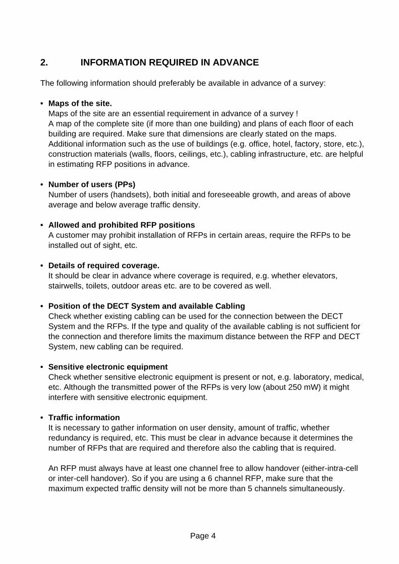
5.2.2. Survey Base Station
The Survey Base Station consists of a dedicated casing and incorporates:
- Dedicated Base Station- Two battery trays (each one for 4 AA-size batteries)- On/off slide-switch- Red/Green coloured LED- Threaded hole (3/8" UNC) in the bottom of the casing for attachment to a tripod.
In figure 4, the Site Survey Base Station is depicted.
Figure 4. Survey Base Station
Front view on SiteSurvey Base Station
Batterycompartment
Batterycompartment
OnOffOffTone
Sourceinput
Threadedhole (3/8"UNC) for
mounting toa stand
LEDIndicator
ExternalAntenna’s
ExternalAntenna Connectors

Page 14
The Site Survey Kit includes batteries (NiMH types) for the Base Station. It also includestwo chargers. The following procedure explains how to charge the batteries
Procedure with pre-discharge:
1. Make sure that the batteries that you want to charge, are NiMH or NiCd types.
2. Insert the batteries with correct polarity into the recesses.
3. Plug the charger into the 230 V socket. Batteries which are not fully discharged, willnow be discharged automatically to approx. 1 V.During this procedure the red LED will be lit.It is advised to discharge and then charge all batteries once a week.
4. As soon as the pre-discharge is finished, the charger will automatically switch tocharging mode (green LED will be lit continuously).
5. When all batteries are fully charged, the charger will switch to a pulse trickle charge(green LED flashes). Maintaining a trickle charge prevents any discharge. Thebatteries can remain in the charger and are ready for use as and when they arerequired.
Charging procedure without pre-discharge:
1. Make sure that the batteries that you want to charge, are NiMH or NiCd types.
2. Plug the charger into a 230 V socket.
3. Insert the batteries into the charger, ensuring that the correct polarity is observed.The charging starts immediately which is indicated by a continuous green LED).
4. When all batteries are fully charged, the charger will switch to a pulse trickle charge(green LED flashes). Maintaining a trickle charge prevents any discharge. Thebatteries can remain in the charger and are ready for use as and when they arerequired.
Note: Never use dry batteries in the charger, only NiCd or NiMH batteries. Remember,any interruption in the charging process, such as disconnection from the mainssocket or removal of the battery, will result in resetting the charging process. Forthis reason, leave the batteries in the connected charger until required.
For operating the Survey Base Station the following batteries can be used:

Page 15
- Standard AA-size Alkaline penlight batteries (NON-Rechargeable !)(Nominal Operation time 8 hrs.)
- AA-size rechargeable 1100 mAh NiMH batteries.(Nominal Operation time 6 hrs.)
- AA-size rechargeable NiCd batteries.(Nominal Operation time 4 hrs.)
5.2.3. Tone Generation and Tone Source
The Survey Base Station is equipped with a Tone Generator and a tone Source input. Thetone generator in the Base Station generates a tone for only 50 seconds. Then theconnection will be broken.The Tone source input can be used instead of using the tone generator in the BaseStation. The connector for this input is a normal 3,5 mm jack plug.Note that if you supply a constant tone to this input, and you go off hook, then theconnection will be broken after 50 seconds as well. If you supply speech to the tone sourceinput, and you go off-hook, then the connection will not be broken.
5.2.4. LED Indications on Survey Base Station
The LED indicator displays one of the following statuses:
- Green blinking Base Station starting up, just wait a few seconds.- Green steady on Base Station operational
5.2.5. Survey Handsets and Charging Stations
The Site Survey Kit incorporates the following handsets with associated charging stations:
• 3x C922C922 is a dedicated handset!! Therefore this handset cannot be replaced by anotherC922.The handset is supplied with a standard type desktop charging station.Details of operation, apart from site survey issues, are given in the associated userguide.
• Onis HandsetThe handset is supplied without battery charger, as it support the use of normal AAtype batteries. The handset is NOT required for the Site Survey / Deployment activityitself. It might be required (in very exceptional cases) to (de)subscribe a handset to thebase station. Note that this is normally NEVER necessary (!!) because the C922

Page 16
handsets are already subscribed to the Base Station. The C922 handsets are matchedwith the Base Station for valid signal strength readout.
Note: The supplied handsets are subscribed/registered to the Survey Base Station ondelivery. This can be checked by means of the section: “6.1. Checking The SurveyEquipment For Correct Operation”.

Page 17
6. PREPARATION
The thoroughness with which all preparations can be done depends upon the informationavailable regarding the site to be surveyed.
6.1 CHECKING THE SURVEY EQUIPMENT FOR CORRECT OPERATION
To check the equipment execute the following procedure:
1. Make sure that the Survey Base Station and handset batteries are fully charged.
2. Install the two external antenna’s at the Base Station.
3. If not yet done, install the batteries in the Base Station and switch the Base Station on.Check that the LED at the Base Station is steady on.
4. Make sure that the C922 handsets are switched on and “on-hook”.
5. Go “off-hook” on one C922. A tone must be heard. If not, check that the Base Station isswitched on and that the battery of the handset is fully charged.Repeat this step for each C922 handset.(If everything is OK, and yet you don’t hear a tone on one handset, the problem mightbe that the handset is not subscribed. In that case, consult Appendix C.)
6. Put the Base Station in a corridor. Keep a distance of 20 metres between the C922handsets and the Base Station and make sure that there is nothing/nobody in-between.
7. Press: R***76# on each C922 handset.
8. Now you are in a menu. Scroll to “Site Survey” and press “OK”.The following is displayed (for explanation of the fields, consult section 7.2. “Setting upthe Equipment”)
9. Check that the RSSI reading is between -62 and –67 dBm. If not then, the Survey Kitmust be repaired.
�FERSSI -65 dBmRFPI 1000123456TelBook Menu
Page 18
6.2. MAPS
Maps should be prepared in a format that can be easily carried around the site. Whenenlarging or reducing the format make sure that dimensions are not lost (be sure that thereis a calibration line at each map). Also, each map must be clearly marked with the locationidentity.
6.3. OTHER PAPERWORK
Before executing a survey, a query list needs to be assembled, listing the information to begathered during the survey apart from the radio coverage information (see chapter 9.).
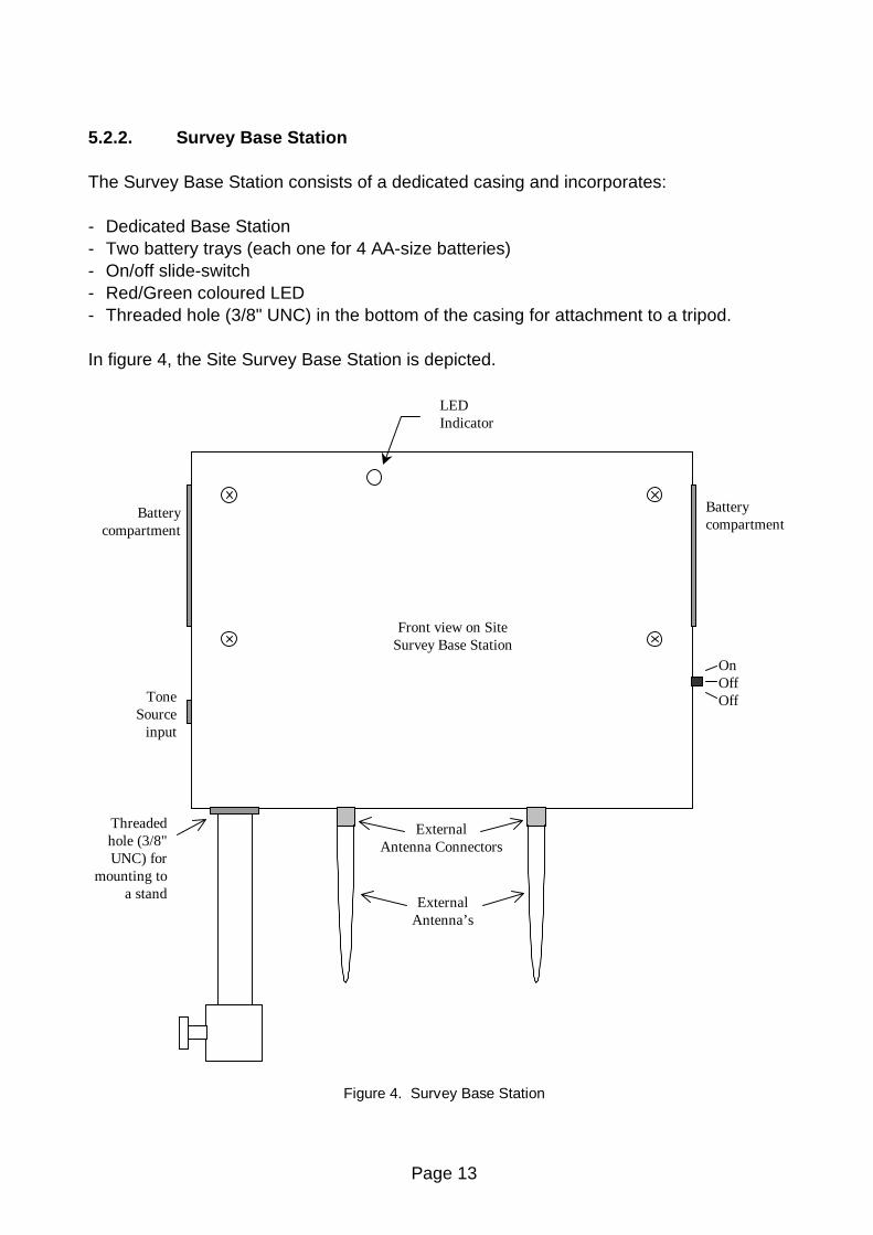
6.4. RFP POSITIONS DURING SURVEY
If possible, plan the RFP positions to be measured before starting the survey, includingalternative configurations, taking into account estimated cell sizes.The following RFP ranges can be used as a rough guide to planning the RFP positions:
- In the line of sight the RFP has a range of about 80m.- In halls the RFP has a range of < 80m.- In buildings the RFP has a range of about 15-40m. This assumes that walls are made of
light brick, plasterboard or wallboard with metal frames. Normal electrical wiring, centralheating pipes, office furniture and desktop computer equipment have no significanteffect. The signal shadowing effect of stairways, lift shafts shielded rooms etc. should beconsidered.
The following items may well cause shadowing of the radio signal:- Thick walls, especially cavity walls and reinforced concrete walls.- Windows or glass in doors with steel wire reinforcement or metallic reflection film.- Steel doors, partitions or walls.- Fire resistant doors.- A wall of steel cabinets, large computer equipment or machinery.- Thick concrete floors.
During the site survey, be aware of the following:
- Choose a corridor or other large open space rather than an enclosed area so that theradio signal passes through as few walls as possible to reach as large an area aspossible.
- Radio reception inside a vehicle may be poor unless very close to the RFP.

Page 19
- The RFP should be placed high enough to be unaffected by surrounding objects. Forexample, an RFP in a car park needs to be placed higher than a vehicle that may beparked next to it.
- RPFs must be placed at least 1 metre apart from each other!
- The presence of another un-synchronised DECT System or similar system in adjacentbuildings may cause interference.
- An RFP or a PP might interfere with sensitive laboratory equipment, medical equipmentetc. (E.g. do not install an RFP in an operating-room in a Hospital!)
- Check that no significant interference from un-suppressed engines or electric motorshas been experienced.
6.5. CUSTOMER PREPARATION
If a customer contact person is assigned, this gives the opportunity to collect additionalinformation as required, set times and dates, discuss accessibility (access to certain areasmay be restricted at certain times or altogether, some areas may be locked), and give thecustomer an idea of what to expect i.e. how a survey is done. It may be a good idea tohave other employees on the customer site informed that a 'stranger' with a handset mightbe seen wandering around in their workspace.

Page 20
7. EXECUTION
7.1. GENERAL
Site Survey execution should be done with at least one, preferably two persons.There are three main criteria for the cell boundary:
- Voice quality;- Signal strength- Frame errors (if there are audible clicks in the voice connection).
To check the voice quality, a voice connection should be set-up between two persons. Oneperson should stay close to the Base Station, the other one should move away todetermine the cell boundary. This gives a good impression on the radio signal behaviourclose to the base station and at the cell boundary.The person determining the cell boundary checks on voice quality, signal strength andframe errors. He/she can do this by means of a single handset with headset, or onehandset for listening and another handset for checking the signal strength.
In figure 5, the functions of the persons are depicted.
Figure 5. Site Survey / Deployment in Action
Signal strength andFrame errormeasurement
Sound qualitycheck
Base Station

Page 21
If you are with two persons, one should stay at the Base Station position and the other oneshould determine the cell boundary.
7.2. SETTING UP THE EQUIPMENT
Before starting the execution make sure that the handset(s) for the site survey aresubscribed to the Survey Base Station. Now execute the following steps:
1. Set-up a Survey Base Station at a planned RFP position.Choose the locations for the Survey Base Station as close as possible to the locationswhere the RFPs can be actually installed. Look also for suitable cable ducts.
2. Switch the Survey Base Station on. The LED should be steady green after a fewseconds. If you go off-hook with one of the extensions the LED will start blinkinggreen.
3. Adjust the tripod to put the Survey Base Station near the ceiling (for an officeenvironment) or as high up as possible in a large area (such as a warehouse). If theSurvey Base Station is outside then put it at a height of about 5 m.
4. Ensure that the handset is receiving the Survey Base Station signal. You can checkthis by going off-hook. You must hear a tone (released after 50 seconds).
5. Write down, or take notice of the value that you see in the idle display.(normally round about –72).
6. Enable the special (measurement) mode in the C922 which you should use for surveypurposes:Press: R ***76#
SURV - 72No user Name
3TelBook Menu
RSSI value for cellboundary, typically forthis handset
Local number

Page 22
7. Now you are in a menu. Scroll to “Site Survey” and press “OK”.Now the PP is ready for the site survey.
The important fields are:
- FEHere you see the Frame Errors. Frame errors may occur from time to time. Each 1seconds the accumulative value over the 1 seconds is displayed!
- RSSIThe RSSI will never be better than about –40dB, because the RSSI value isinternally limited in the C922 to this value.
If the RSSI goes down to ,the value that you have written down (or in mind) of step5 then that is your cell boundary!!!
You are allowed to add -2 to that value, so that the value for the cell boundary ishigher and the cell boundary will be wider. (E.g. instead of –72, you might go to –74). Note that the sound quality will be a bit worse, but in normal circumstances thisis not noticeable.
- RFPI:This is the unique number (PARI) of your Base Station. By means of this numberyou can see that the handset is “locked” to (looks at) your Base Station and not toanother DECT system, if operational in the environment.
(The survey handset should be held at about 1,2m above the ground when makingmeasurements.)
7. Check the speech quality. This can be done in the following ways:
- Set-up a voice connection from the C922 to the C922 handset.Press the “I” button and dial one digit (2, 3 or 4) to set-up a call to another C922.Now you have a voice connection and you can check the speech quality.
�FERSSI -60 dBmRFPI 1000123456TelBook Menu

Page 23
- Just go off-hook with the C922. You will hear a tone for 50 seconds. Then the toneis quit automatically. You can see the difference between the tone that quits and adropped call by watching the display carefully. If the display shows 50 for a veryshort time, then it indicates that the tone was release automatically. If it showssomething else, it means that the call was dropped.
- You can also connect a tone source (CD player, Cassette player with speech) to theBase Station. There is a small 3,5 mm jack input at the left side of the Base Stationbox.If you have connected a music source, you can go off hook and you will hear thetone.Note that if this tone is constant, the connection will be broken after 50 seconds!
Note: The sound should be without “clicks” or other interruptions.If there are sync errors and clicks while you are moving, it may indicate thatthere are a lot of reflections in the area. Reflections are caused by metal walls,etc. Check whether there is a lot of metal in the walls. In some exceptionalcases, DECT cannot be installed in environments with a lot of metal due toexcessive reflections against the walls and ceiling.
Only the cell boundaries need to be determined, it is not necessary to survey thecomplete area within the cell boundary. Staircases, elevator shafts, shielded roomsetc. deserve special attention if seamless coverage is required there. Fire doorsshould be closed.
8. Note the results on the relevant maps. Take care that the relation between the SurveyBase Station position and the corresponding cell is clearly defined, using thenumbering scheme given in chapter 8.Note that for a multi-story building it must be clear on what floor the Survey BaseStation was positioned and that the result may be several cell contours on differentfloors. In this case in particular a careful record must be kept for later unambiguousanalysis.
The position of an elevator shaft, lorry or other large movable object may also effectradio reception. If possible arrange for the object to be moved and check the cellboundary again.
9. Repeat steps 1...10 for the remaining planned RFP positions.Make sure that, when applicable, positions are also measured that may be relevant foralternative configurations.Cells should be at least adjacent to one another; overlap is not required except wheretraffic density requires this.

Page 24
10. It may, at this stage, be necessary to move some of the planned RFP positions or addnew RFP positions to eliminate shadows or optimise cell size. If so, it may also benecessary to do additional measurements to check that the new RFP positions do notcreate other problems.
11. Choose the RFP positions required. This may need to be done in consultation with acustomer engineer.In choosing RFP positions, the required cabling to the DECT System should beconsidered. RFP positions must be defined such that later installation problems areminimised, i.e. the RFP can be physically attached at the planned position and thewiring can be laid with the minimum of effort.
12. Record details of the planned RFP positions, including wiring considerations, specialinstallation instructions etc.Depending on the materials (no metal in it, thin materials etc.) of the ceiling, an RFPcan be concealed above a suspended ceiling, provided it is not of a metalconstruction.An RFP can be installed within a metre or two of the planned position withoutadversely affecting radio reception.
13. To quit the special (measurement) mode in the PP:- Make sure that you are on-hook- Press: R ***76#

Page 25
7.3. HOW TO SURVEY
7.3.1. General
During the execution of a Site Survey, you must make sure that you know all the detailsabout the required coverage, e.g.
- If a car park must be covered, must it be covered for an empty car park, full car park,only out side cars or also inside cars. If also inside the cars, then must this be measuredwith the doors and windows of the cars closed or open etc.
- Must toilets be covered as well, and how good must the voice quality be in a toilet withthe doors closed.
- Are basements to be covered as well, if so, how good must the coverage be.
It is very important that these details are written down on paper, and that the customeragrees with that.
Note: If you do the site survey, make sure that all doors are closed. Close all fire doors aswell.
7.3.2. How to Survey A Single Floor
The following is the basic procedure to determine the cell centre and the cell boundaries.In figure 6, an example of a single floor is depicted.
Figure 6. Example of a Single Floor Coverage.
CP 1
CP 2
BaseStation
CP 3
CP 4

Page 26
The procedure is as follows:
1. Determine the outer points in the building. These points are the so-called “CriticalPoints”. (In figure 6, these are CP1 and CP2).
2. Place the Survey Base Station on CP 1 on a height of approximately 1.2 meters. Walkaway from the Base Station at an angle of roughly 45 degrees. Write down where thecell boundary is.
3. Place the Survey Base Station on CP2 on a height of approximately 1.2. Walk awayfrom the Base Station at an angle of roughly 45 degrees. Write down where the cellboundary is.
4. The best location for the cell centre is where the critical point contours cross.
5. Position the Site Survey Base Station on the CP1/CP2 cross, and raise it to the heightwhere the base station must be fitted.
6. Now check the cell boundary. Check that the RSSI value at CP1 and CP2 aresufficient. Draw the cell on the map.
7. Determine new Critical Points (CP 3 and CP 4 in figure 6) at the external walls andrepeat the procedure from step 1 onwards.
Page 27
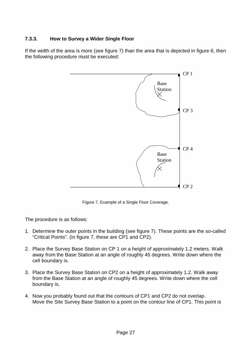
7.3.3. How to Survey a Wider Single Floor
If the width of the area is more (see figure 7) than the area that is depicted in figure 6, thenthe following procedure must be executed:
Figure 7. Example of a Single Floor Coverage.
The procedure is as follows:
1. Determine the outer points in the building (see figure 7). These points are the so-called“Critical Points”. (in figure 7, these are CP1 and CP2).
2. Place the Survey Base Station on CP 1 on a height of approximately 1.2 meters. Walkaway from the Base Station at an angle of roughly 45 degrees. Write down where thecell boundary is.
3. Place the Survey Base Station on CP2 on a height of approximately 1.2. Walk awayfrom the Base Station at an angle of roughly 45 degrees. Write down where the cellboundary is.
4. Now you probably found out that the contours of CP1 and CP2 do not overlap.Move the Site Survey Base Station to a point on the contour line of CP1. This point is
CP 1
CP 2
BaseStation
CP 3
CP 4BaseStation

Page 28
considered as being the cell centre.Measure the cell boundary for cell 1.
5. Move the Site Survey Base Station to a point on the contour line of CP2. This point isconsidered as being the cell centre.Measure the cell boundary for cell 2.
6. Where the cells cross the outer walls of the building, two new Critical Points (CP3 andCP4) are defined.
7. Use the procedure “How to Survey A Single Floor” in section 7.3.2. to determine thecell centre of the next cell
7.3.4. How to Survey a Multi Floor Area
There are two approaches in surveying a multi story building:
1. Survey each floor as individual parts. The radiation between floors is not used forcoverage, but is only used to allow higher traffic density.In this approach you are always sure that the coverage on each floor is reliable.
2. Survey one floor and write down the cell boundaries on the higher and lower floor aswell.Knowing the cells on the higher and lower floors, you can survey these floors, todetermine where additional Base Stations must be placed.
Note: Radiation through floors depends highly on the construction materials of thefloors. These materials are normally reinforced concrete, which gives a lot ofsignal loss. Also, in ceilings there are most likely cable ducts, which producesholes in the coverage on the higher and lower floors. Therefore, coverage viafloors is not always reliable!!!!!

Page 29
7.4. TRAFFIC DENSITY CALCULATIONS
Traffic density calculations must be done to make sure that you have a low blockingprobability in the system.
For traffic calculations you must know:
- the number of users,- the type of users.
There are three user types distinguished:
TRAFFIC APPLICATION ARE ERLANG/USER
Low normal offices 0,05Average Exec-secretary groups 0,1– 0,15
High traffic help desks, Tele-services 0,2 – 0,25
Table 2. Three user types.
With a blocking probability of 0,5% the following maximum Erlang values are allowed perRFP:
1,6 Erlang for a 6 channel RFP5,2 Erlang for a 12 channel RFP
Now you can calculate the traffic density as follows:
Nbr of RFPs = (nbr of users) x Erlang/userMax. load per RFP
Example:
In one cell there will be 20 users: 5 average traffic and 15 low traffic.The load will be: (5 x 0,15) + (15 x 0,05) = 1,5 Erlang
Conclusion: One 6 channel RFP will be sufficient for this cell.

Page 30
8. REPORTING RESULTS
It is important to make a comprehensive survey report that records test results andprovides useful information for the engineer who is to actually install the equipment. Thefollowing information should be included in the survey report (see chapter 10 for a possibletemplate):
- A description of the site, explaining which buildings and grounds are to be included inthe report. A description of the topography of outdoor areas may be useful.
- A specification of the construction of the buildings and construction materials.- Determine the customer requirements for:
. the number of handsets
. required coverage
. performance requirements (traffic density, grade of service etc.)- The location of the DECT System.- Cabling details. Include a specification of cables already present on the site and a list of
new cabling required. Include the distance between RFP and the DECT System forexisting and new cabling.
- Copies of the maps of the site with the positions of Survey Base Stations and the cellboundaries.. Different cell boundaries can be marked with different patterns to avoid confusion i.e.
dotted, dashed, dot dash etc. Do not use colours, as these may be lost whenphotocopying.
. Use the following numbering conventions :
xCyy refers to the identity of the cell, where:x: is the level at which the measurement was made.
(-1 is basement, 0 is ground floor, 1 is 1st floor etc.)yy: is the RFP position number which was being measured.
Example of labelling floor plans:0C1 = Ground floor Cell 10C2 = Ground floor Cell 21C3 = First floor Cell 32C4 = Second floor Cell 4-1C5 = Basement/cellar Cell 5
- A list of possible configurations will help the customer to decide exactly what is required.- A specification of where RFPs should be placed. This can be marked on the survey
map, but additional information such as height and fixing instructions should be includedwhere appropriate.
- A specification of the areas that will be covered by the RFPs and areas that may causeproblems. This can be useful when testing the system.

Page 31
The theoretical maximum number of overlapping cells is 10 for 12 channel RFPs and 20for 6 channel RFPs, if all timeslots and frequencies are used. If not all timeslots andfrequencies are used, this value is higher. However this is unlikely to be reached inpractical situations.
For a large site where a thorough survey has been impossible, it may be prudent to add10% extra RFPs to the product offer to allow for unforeseen problem areas.
An example of a survey report is given in appendix A.

Page 32
9. CHECKLIST FOR SURVEY DATA
- Building characteristics (list for each building). Building identification (refer to maps if available). Type of use. Dimensions (refer to maps if available). Number of floors (refer to maps if available). Height per floor. Partitioning per floor (refer to floor plans if available). Construction details (type of construction and materials used)
- Radio coverage requirementsList areas where radio coverage is not absolutely required or are to be excluded fromradio coverage.
- Radio coverageList areas where radio coverage is not feasible or requires specific RFPs.
- Objects inside buildingsDetails of furniture, cupboards, machinery, etc. in the interior of buildings per floor.
- DECT SystemPosition of the DECT System.
- Connections between DECT System and RFP(s)For each RFP the following details of its connection to a DECT System are required:. length of cable between DECT System and RFP.. whether existing cabling is present that might be used and if so, the type of cabling
(twisted pairs, star quad, wire diameter, etc.), presence of free pairs, etc.. cabling layout (risers, horizontal wiring, distribution frames) and whether existing
cabling can be used or new wiring is required.

Page 33
10. DECT SURVEY REPORT TEMPLATE
Number :.......................................................
From : ..............................................................................................................................[Engineer doing the survey]
To : ..............................................................................................................................[Sales Manager]
Copy : ..............................................................................................................................
Date :......................... /....... /........
1. Site :.................................................................................................................................[Full address of site]
2. Execution of surveyEngineers : .............................................................................................. [Names and addresses of engineers who executed the survey]
Customer engineer(s) : ............................................................................................. [Name and address of customer engineer(s)]
Date : [Date of survey]
3. Outline description of site [Short description of site (dimensions, environment, number/ type of buildings, etc.]
4. Number of handsets and expected traffic [Description of expected traffic and indication of above or below average traffic
areas]
5. Test results. [This should include the site maps and any additional information that may be useful]
6. Connections DECT System - RFPs
6.1 Location of DECT System. [Indicate the location of the DECT System]

Page 34
6.2 Existing cabling [Indicate what cabling is available and how it is distributed across the site]
6.3 Connection of RFPs and cable lengths [List for planned RFP approximate cable length, and whether existing wiring can be used or new cabling is required]
6.4 RFP installation [For each RFP indicate exactly where it can be installed, e.g. "in the corridor against the wall of room 32, 2.5 m high") and whether customer restrictions apply as to where RFPs may be installed]
7. Possible configurations [List alternative configurations regarding the deployment of RFPs. Refer to coverage maps and detail areas where coverage cannot be guaranteed]
Page 35
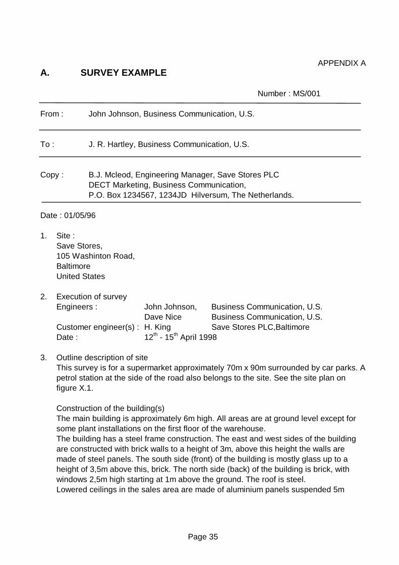
APPENDIX AA. SURVEY EXAMPLE
Number : MS/001
From : John Johnson, Business Communication, U.S.
To : J. R. Hartley, Business Communication, U.S.
Copy : B.J. Mcleod, Engineering Manager, Save Stores PLCDECT Marketing, Business Communication,P.O. Box 1234567, 1234JD Hilversum, The Netherlands.
Date : 01/05/96
1. Site :Save Stores,105 Washinton Road,BaltimoreUnited States
2. Execution of surveyEngineers : John Johnson, Business Communication, U.S.
Dave Nice Business Communication, U.S.Customer engineer(s) : H. King Save Stores PLC,BaltimoreDate : 12th - 15th April 1998
3. Outline description of siteThis survey is for a supermarket approximately 70m x 90m surrounded by car parks. Apetrol station at the side of the road also belongs to the site. See the site plan onfigure X.1.
Construction of the building(s)The main building is approximately 6m high. All areas are at ground level except forsome plant installations on the first floor of the warehouse.The building has a steel frame construction. The east and west sides of the buildingare constructed with brick walls to a height of 3m, above this height the walls aremade of steel panels. The south side (front) of the building is mostly glass up to aheight of 3,5m above this, brick. The north side (back) of the building is brick, withwindows 2,5m high starting at 1m above the ground. The roof is steel.Lowered ceilings in the sales area are made of aluminium panels suspended 5m

Page 36
above the ground. Lowered ceilings in the staff area are also aluminium panelssuspended 3m above the ground.
The petrol station consists of a single brick building and a covered petrol pump area.
4. Number of handsets and expected trafficThe maximum number of portable handsets required is 12, but the number is expectedto rise to 25 in the future.
5. Test results:Refer to the site map, figure A.1. The RFP and cells are numbered as follows:
xRyy refers to the identity of the RFP, where :x is the level (-1 is basement, 0 is ground floor, 1 is 1st floor etc.)yy is the RFP position number. This number should be unique.
xCyy refers to the identity of the cell, where :x is the level at which the measurement was made (-1 is basement, 0 is
ground floor, 1 is 1st floor etc.)yy is the RFP position number which was being measured.
6. Connections DCCs - RFPs
6.1 Location of the DECT SystemThe DECT System is located in the staff entrance hall.One DCC board is sufficient to connect four RFPs.
6.2 Existing cablingAll cabling is 0,5 mm unshielded twisted pair. Cables are distributed in cable ductsthroughout the supermarket in the floor and above the lowered ceiling. There is acable to the petrol station building with spare pairs.Cable runs are expected to be less than 200 m using existing spare pairs.
6.3 Connection of RFPs and cable lengths- RFP 0R02 cable length : 35m using existing cables.- RFP 0R03 cable length : 27m using existing cables.- RFP 0R04 cable length : 150m using existing cables.- RFP 0R05 cable length : 15m using existing cables.
6.4 RFP installationThe RFPs are positioned as follows :- RFP 0R02 is fixed to the wall inside the sales area at approximately 1m under the
lowered ceiling.- RFP 0R03 is fixed to the outside wall at a height of approximately 3m.

Page 37
- RFP 0R04 is fixed at a convenient location at the petrol station at a height of 2,5mto 3m.
- RFP 0R05 is fixed at a convenient location in the staff entrance hall.
7. Possible configurations:Configuration 1
The minimum configuration would have RFPs at positions 0R02 and 0R03 plus anRFP at position 0R04 to cover the petrol station building.The cell coverage would be as follows :- RFP 0R02 covers the sales area, the cold store, staff area and part of the offices.- RFP 0R03 covers the offices, most of the staff area and the north of the building.- RFP 0R04 all the outside areas to the south and east of the building, including
the loading bay and staff car park.The RFP tested at position 0R01 is not required.
Note: There is no redundancy; failure of an RFP would result in a large area beingout of range of any other RFP.
Configuration 2This configuration is the same as configuration 1, but with the addition of an RFP atlocation 0R05. This covers most of the offices and staff area. This will give someredundancy in the event of RFP 0R02 or 0R03 failing.This configuration requires five RFPS.

Page 38
Figure A.1. Example Site Plan.

Page 39
APPENDIX B
B. ESTIMATION OF THE NUMBER OF RFPs
B.1. GENERAL
A rough estimation of the number of RFPs, can be useful for an initial negotiation about anew DECT system.
Note: This estimation method is based on “average sites” and is not applicable for anysite. The result is only an indication and must not be used for the final product offer.A Site Survey is always required to determine the exact number of RFPs.No rights can be obtained from these estimation tables.
This estimation method is based on tables. These tables are based on the followingassumptions:
- No radiation between floors.- Average building types.- Average call density.
There are two tables for two types of estimations:
• Estimation for coverage of typical indoor environments .This gives information about the number of RFPs required for typical indoorenvironments. The information is given in table B.1.
• Estimation for coverage in typical open space (indoor/outdoor)In table B.1 you find information about coverage in an open space environment.
A complex site may be more easily split into areas which are estimated separately and theresulting number of RFPs totalled together.One example of this would be a site with an office building, an open warehouse and a carpark, using table B.1 for the offices and table B.2 for the warehouse and the car park.

Page 40
To use the estimation tables in this chapter, execute the following procedure:
1. Collect site info from the customer.
2. Find out the length(s) and the width(s) of the area(s) to be covered.Round up these dimensions to the nearest multiple of 20 metres.
3. Find out if the single area(s) of the site fall(s) within the scheme for "Estimation forcoverage in typical Open Space” and calculate the number of RFPs for this/thesearea(s).
4. The remaining areas are most likely “Typical Indoor Environments”. If so, calculate thenumber of RFPs according to the table for “Estimation for coverage of typical IndoorEnvironments”.If there are parts of the site that do not fit into the specification “Typical Indoor” or“Typical Outdoor” then, you cannot use the estimation tables at all!!
5. Find out how many handsets will be purchased for use on the system
6. Remember that the customer can always add more handsets in the future once thebasic infrastructure (RFPs and common equipment) is in place.

Page 41
B.2. ESTIMATION FOR COVERAGE OF TYPICAL INDOOR ENVIRONMENTS
Table B.1. gives information about the number of RFPs, that are required for estimation thecoverage of typical indoor environments. Using the table, bear in mind the followingremarks:
• Using the length and width of each area, rounded up to multiples of 20 metres, look-upthe number of RFPs from the table B.1.
• This table have been calculated on the basis that each RFPs provides 1200 sq.m.coverage.
• The resulting estimate is used for budgetary purposes to guide the customer onwhether to proceed with a site survey.
• A firm price can only be quoted after a Site Survey.
• A complex site may be more easily split into areas which are estimated separately andthe resulting number of RFPs totalled together.One example of this would be a site with an office building, an open warehouse and acar park, using table B.1 for the offices and table B.2 for the warehouse and the carpark.
Dimensions
(m)20 40 60 80 100 120 140 160 180 200 220 240 260 280
20 1 1 2 2 3 3 4 4 5 5 6 6 7 7
40 1 2 2 3 4 4 5 6 6 7 8 8 9 10
60 2 2 3 4 5 6 7 8 9 10 11 12 13 14
80 2 3 4 6 7 8 10 11 12 14 15 16 18 19
100 3 4 5 7 9 10 12 14 15 17 19 20 22 24
120 3 4 6 8 10 12 14 16 18 20 22 24 26 28
140 4 5 7 10 12 14 17 19 21 24 26 28 31 33
160 4 6 8 11 14 16 19 22 24 27 30 32
180 5 6 9 12 15 18 21 24 27 30 33
200 5 7 10 14 17 20 24 27 30 34
220 6 8 11 15 19 22 26 30 33
240 6 8 12 16 20 24 28 32
260 7 9 13 18 22 26 31
280 7 10 14 19 24 28 33
Table B.1: Estimated number of required RFPs for coverage of typical indoor environments.

Page 42
B.3. ESTIMATION FOR COVERAGE IN TYPICAL OPEN SPACE
Table B.2. gives information about the number of RFPs, that are required for estimation forcoverage in typical open space (indoor/outdoor). Using the table, bear in mind the followingremarks:
• Using the length and width of each area, rounded up to multiples of 20 metres, look-upthe number of RFPs from the table B.1.
• This table have been calculated on the basis that each RFP provides 2400 sq.m.coverage
• The resulting estimate is used for budgetary purposes ONLY, to guide the customer onwhether to proceed with a site survey.
• A firm price can only be quoted after a Site Survey.
Dimensions
(m)20 40 60 80 100 120 140 160 180 200 220 240 260 280
20 1 1 1 1 2 2 2 2 3 3 3 3 4 4
40 1 1 1 2 2 2 3 3 3 4 4 4 5 5
60 1 1 2 2 3 3 4 4 5 5 6 6 7 7
80 1 2 2 3 4 4 5 6 6 7 8 8 9 10
100 2 2 3 4 5 5 6 7 8 9 10 10 11 12
120 2 2 3 4 5 6 7 8 9 10 11 12 13 14
140 2 3 4 5 6 7 9 10 11 12 13 14 16 17
160 2 3 4 6 7 8 10 11 12 14 15 16 18 19
180 3 3 5 6 8 9 11 12 14 15 17 18 20 21
200 3 4 5 7 9 10 12 14 15 17 19 20 22 24
220 3 4 6 8 10 11 13 15 17 19 21 22 24 26
240 3 4 6 8 10 12 14 16 18 20 22 24 26 28
260 4 5 7 9 11 13 16 18 20 22 24 26 29 31
280 4 5 7 10 12 14 17 19 21 24 26 28 31 33
Table B.2. Estimated number of required RFPs for coverage of typical open space (indoors and outdoors)

Page 43
APPENDIX C
C. (DE-)SUBSCRIBING THE SURVEY HANDSETS
Caution: - Subscribing/registering the handsets, is normally never necessary!!!! Only ifthe handsets are not subscribed anymore (very exceptional) then you mustsubscribe the handset(s) again, or if you have to replace a handset.
- If you need to replace a handset, you must de-subscribe the existing handsetin advance. After de-subscribing the existing handset, you can subscribe thenew handset
- Never de-subscribe the “Onis” handset! This handset is only used for service,and not for the execution of the Site Survey.Carefully keep the “Onis” handset with the Base Station. If lost, the kit is notrepairable anymore!!!
C.1. DE-SUBSCRIPTION PROCEDURE FOR A C922
The De-subscription procedure removes the relation between the Base Station and thehandset. This means that the handset cannot be used anymore on the Base Station,unless it is subscribed again.
The procedure for de-subscribing the C922 handset is as follows:
1. Make sure that the Base Station is switched on and operational. Also make sure thatthe “Onis” handset is operational with fully charged batteries.
2. Write down the RSSI value (SURV – xx) and the local number that is displayed on the“idle” display of the handset (C922) that you want to de-subscribe. You need to enterthese value if you want to subscribe the same handset again.
SURV - 72No user Name
3TelBook Menu
RSSI value for cellboundary, typically forthis handset
Local number

Page 44
3. At “Onis” handset:Press the menu button ( R/→ )
4. Scroll to “SETUP” and press “OK”.
5. Scroll to “REMOVE HS” and press “OK”.
6. Scroll to the local number of the handset that you want to remove. The local number isthe internal extension number (one digit), which is visible in the “idle” display of thehandset that you want to remove (see step 2).
7. Press “OK”.
8. The handset requests for a “Code”. This is the four digits “Authentication Code” thatyou find at the rear side of the Survey Base Station.The following is an example of the notation:
RC 1234.
9. Press “OK”. You will hear a confirmation beep.
10. At “Onis” handset, press the menu button ( R/→ )
C.2. SUBSCRIPTION PROCEDURE FOR A C922
The procedure for subscribing the C922 handset is as follows:
1. Switch power of Survey Base Station off and on to put it in Site Survey mode. TheSurvey Base Station is in subscription mode for approx. 60 seconds. So, you mustexecute steps 2 till 9 within 60 seconds!!!
2. Write down the RSSI value (SURV – xx) and the local number that is displayed on the“idle” display of the handset (C922) that you want to de-subscribe. You need to enterthis value in step 7.If there is no value in the display, because it is already de-subscribed, then you shouldhave this value available as result of the de-subscription procedure in section C.1.
3. At C922:Press: R 6Select “New”
4. Now the handset displays “Enter PARK”. Don’t enter a PARK, just make sure that thereis no other DECT system in the environment that is in subscription mode.Press “OK”.

Page 45
5. You must now enter the “Authentication Code”. This is a four-digit code, which you canfind on the rear side of the Survey Base Station.The following is an example of the notation:
RC 1234.
6. Then press “OK”.
7. Enter a system name. Enter the following: SURV-xx , where “xx ” is the RSSI value ofthe cell boundary. This value was already in the display before you de-subscribed thehandset (see step 2 in section C.1, or Step 2 in this section).The value that you enter, will be shown on the display if the handset is idle.Press “OK”
8. Now the handset requests for a “Local Number”. Enter the local number of the handset.This value was already in the display before you de-subscribed the handset (see step 2in section C.1, or Step 2 in this section).The value that you enter, will be shown on the display if the handset is idle.Press “OK”.
9. Now the subscription procedure is finished. If you go “off-hook” you should hear a tone.
C.3. (DE-)SUBSCRIPTION “ONIS” HANDSET
Never de-subscribe or re-subscribe the “Onis” handset! This handset is only used forservice, and not for the execution of the Site Survey.Carefully keep the “Onis” handset with the Base Station. If lost, the kit is not repairableanymore!!!