SUBMITTAL DATA: PKA-A12HA7 & PUY-A12NKA7(-BS) · 2019-10-09 · Model Number Indoor Unit PKA-A12HA7...
8
Job Name: System Reference: Date: Indoor Unit: PKA-A12HA7 Outdoor Unit: □ PUY-A12NKA7 □ PUY-A12NKA7-BS INDOOR UNIT FEATURES • Sleek, compact design • Simple installation • Vane setting for air flow direction control • Auto fan speed mode • Ideal for spaces such as server rooms, daycare centers, classrooms, churches, small offices, and more OUTDOOR UNIT FEATURES • Variable speed INVERTER-driven compressor • Power receiver pre-charged with refrigerant volume for piping length up to 100 ft (70 ft. for A12/18/24/30) • Low ambient cooling down to -40ºF providing 100% capacity (only for PUY models with wind baffles installed) • 24-hour continuous operation (cooling mode) • High pressure protection • Fast restarts in cooling mode (15 seconds for 12/18/36/42; 50 seconds for 24/30) • Superior energy and operational efficiency SUBMITTAL DATA: PKA-A12HA7 & PUY-A12NKA7(-BS) 12,000 BTU/H WALL-MOUNTED AIR-CONDITIONING SYSTEM Specifications are subject to change without notice. © 2018 Mitsubishi Electric Trane HVAC US LLC. All rights reserved. P-SERIES
Transcript of SUBMITTAL DATA: PKA-A12HA7 & PUY-A12NKA7(-BS) · 2019-10-09 · Model Number Indoor Unit PKA-A12HA7...

Job Name:
System Reference: Date:
Indoor Unit:PKA-A12HA7
Outdoor Unit:□ PUY-A12NKA7□ PUY-A12NKA7-BS
INDOOR UNIT FEATURES• Sleek, compact design• Simple installation• Vane setting for air flow direction control• Auto fan speed mode• Ideal for spaces such as server rooms, daycare centers, classrooms, churches, small offices, and more
OUTDOOR UNIT FEATURES• Variable speed INVERTER-driven compressor• Power receiver pre-charged with refrigerant volume for piping length up to 100 ft (70 ft. for A12/18/24/30)• Low ambient cooling down to -40ºF providing 100% capacity (only for PUY models with wind baffles installed)• 24-hour continuous operation (cooling mode)• High pressure protection• Fast restarts in cooling mode (15 seconds for 12/18/36/42; 50 seconds for 24/30)• Superior energy and operational efficiency
SUBMITTAL DATA: PKA-A12HA7 & PUY-A12NKA7(-BS)12,000 BTU/H WALL-MOUNTED AIR-CONDITIONING SYSTEM
Specifications are subject to change without notice. © 2018 Mitsubishi Electric Trane HVAC US LLC. All rights reserved.
P-SERIES
Model Number
Indoor Unit PKA-A12HA7
Outdoor UnitPUY-A12NKA7
PUY-A12NKA7-BS
Cooling1
Maximum Capacity Btu/h 12,000
Rated Capacity Btu/h 12,000
Minimum Capacity Btu/h 5,800
Maximum Power Input W 1,000
Rated Power Input W 1,000
Moisture Removal Pints/h 2.0
Sensible Heat Factor 0.81
Power Factor % 94.5
EfficiencySEER 20.8
EER1 12.0
Electrical
Voltage, Phase, Frequency 208 / 230V, 1-phase, 60 Hz
Guaranteed Voltage Range V AC 198 – 253
Voltage: Indoor - Outdoor, S1-S2 V AC 208 / 230
Voltage: Indoor - Outdoor, S2-S3 V DC 24
Voltage: Indoor - Remote controller V DC 12
Recommended Fuse/Breaker Size A 15
Recommended Wire Size (Indoor - Outdoor) AWG 14
Indoor Unit
MCA A 1
Fan Motor Full Load Amperage A 0.33
Fan Motor Output W 30
Airflow Rate, Dry CFM 320-370-425
Airflow Rate, Wet CFM 290-335-380
External Static Pressure in.WG n/a
Sound Pressure Level dB(A) 36-40-43
Drain Pipe Size In. (mm) 5/8 (16)
Condensate Lift Mechanism, Max. Distance In. (mm) n/a
Heat Exchanger Type Plate fin coil
External Finish Color White Munsell 1.0Y 9.2/0.2
Unit Dimensions
W: In. (mm) 35-3/8 (898)
D: In. (mm) 9-13/16 (249)
H: In. (mm) 11-5/8 (295)
Package Dimensions
W: In. 39-6/16
D: In. 15-12/16
H: In. 13-6/16
Unit Weight Lbs. (kg) 29 (13)
Package Weight Lbs. 33
Indoor Unit OperatingTemperature range
Cooling Intake Air Temp (Maximum / Minimum) °F 90 DB, 73 WB / 66 DB, 59 WB
SPECIFICATIONS: PKA-A12HA7 & PUY-A12NKA7(-BS)
Specifications are subject to change without notice. © 2018 Mitsubishi Electric Trane HVAC US LLC. All rights reserved.
Model Number
Indoor Unit PKA-A12HA7
Outdoor UnitPUY-A12NKA7
PUY-A12NKA7-BS
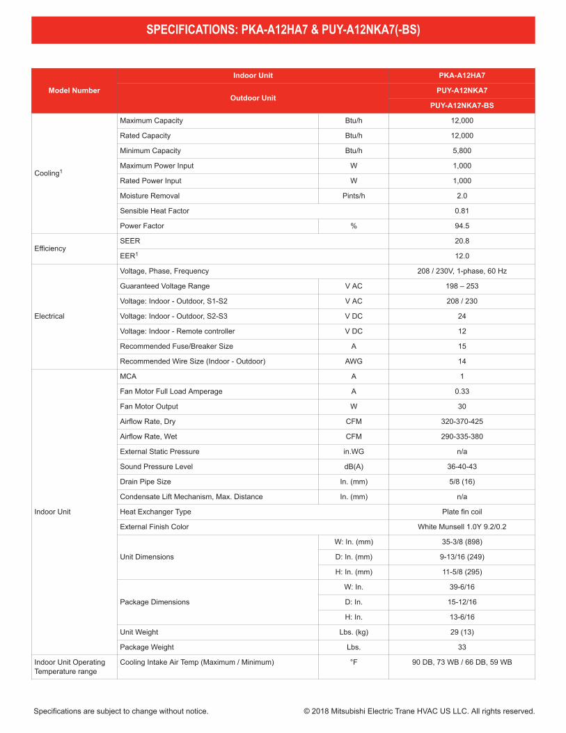
Outdoor Unit
MCA A 11
MOCP A 28
Fan Motor Full Load Amperage A 0.50
Fan Motor Output W 46
Airflow Rate CFM 1,590
Refrigerant Control Electronic Expansion Valve
Heat Exchanger Type Cross fin
Sound Pressure Level, Cooling1 dB(A) 44
Compressor Type INVERTER-driven twin rotary
Compressor Model SNB092FNCM
Compressor Rated Load Amps A 7
Compressor Locked Rotor Amps A 12
Compressor Oil Type // Charge oz. FV50S // 12
External Finish Color Ivory Munsell 3Y 7.8/1.1
Base Pan Heater n/a
Unit Dimensions
W: In. (mm) 31-13/16 + 7/16 (809+62)
D: In. (mm) 11-3/16 (300)
H: In. (mm) 24-13/16 (630)
Package Dimensions
W: In. 37-1/16
D: In. 16-3/16
H: In. 27-7/16
Unit Weight Lbs. (kg) 92 (41)
Package Weight Lbs. (kg) 104 (47)
Outdoor Unit OperatingTemperature Range
Cooling Intake Air Temp (Maximum / Minimum) °F 115 DB / -40* DB
RefrigerantType R410A
Charge Lbs, oz 4 lbs, 7 oz
Piping
Gas Pipe Size O.D. (Flared) In.(mm) 1/2 (12.7)
Liquid Pipe Size O.D. (Flared) In.(mm) 1/4 (6.35)
Maximum Piping Length Ft. (m) 165 (50)
Maximum Height Difference Ft. (m) 100 (30)
Maximum Number of Bends 15
SPECIFICATIONS: PKA-A12HA7 & PUY-A12NKA7(-BS)
Specifications are subject to change without notice. © 2018 Mitsubishi Electric Trane HVAC US LLC. All rights reserved.
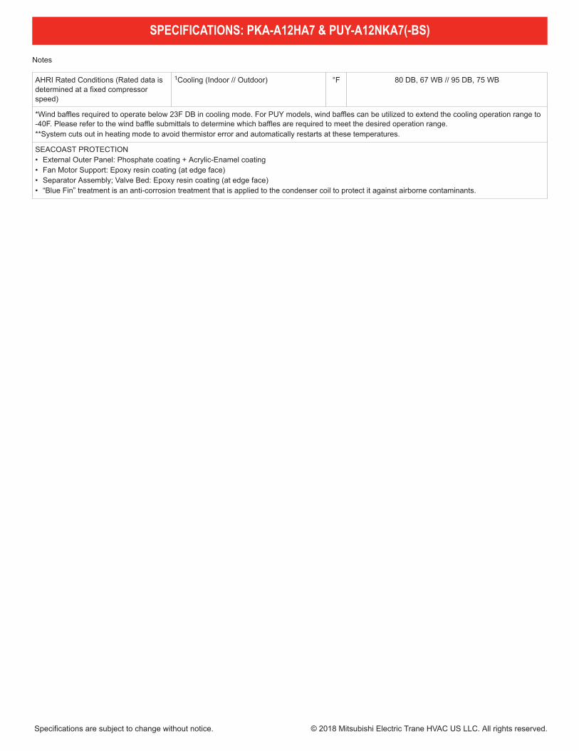
Notes
AHRI Rated Conditions (Rated data isdetermined at a fixed compressorspeed)
1Cooling (Indoor // Outdoor) °F 80 DB, 67 WB // 95 DB, 75 WB
*Wind baffles required to operate below 23F DB in cooling mode. For PUY models, wind baffles can be utilized to extend the cooling operation range to-40F. Please refer to the wind baffle submittals to determine which baffles are required to meet the desired operation range.**System cuts out in heating mode to avoid thermistor error and automatically restarts at these temperatures.
SEACOAST PROTECTION• External Outer Panel: Phosphate coating + Acrylic-Enamel coating• Fan Motor Support: Epoxy resin coating (at edge face)• Separator Assembly; Valve Bed: Epoxy resin coating (at edge face)• “Blue Fin” treatment is an anti-corrosion treatment that is applied to the condenser coil to protect it against airborne contaminants.
SPECIFICATIONS: PKA-A12HA7 & PUY-A12NKA7(-BS)
Specifications are subject to change without notice. © 2018 Mitsubishi Electric Trane HVAC US LLC. All rights reserved.
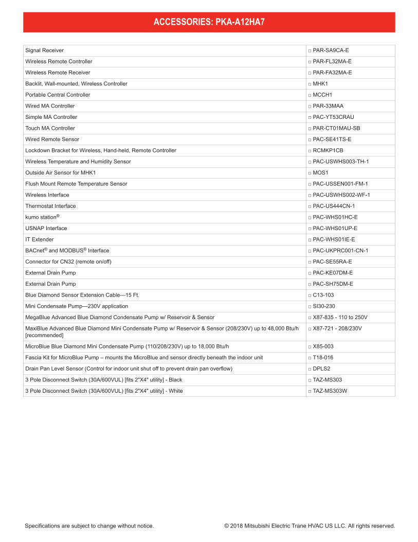
Signal Receiver □ PAR-SA9CA-E
Wireless Remote Controller □ PAR-FL32MA-E
Wireless Remote Receiver □ PAR-FA32MA-E
Backlit, Wall-mounted, Wireless Controller □ MHK1
Portable Central Controller □ MCCH1
Wired MA Controller □ PAR-33MAA
Simple MA Controller □ PAC-YT53CRAU
Touch MA Controller □ PAR-CT01MAU-SB
Wired Remote Sensor □ PAC-SE41TS-E
Lockdown Bracket for Wireless, Hand-held, Remote Controller □ RCMKP1CB
Wireless Temperature and Humidity Sensor □ PAC-USWHS003-TH-1
Outside Air Sensor for MHK1 □ MOS1
Flush Mount Remote Temperature Sensor □ PAC-USSEN001-FM-1
Wireless Interface □ PAC-USWHS002-WF-1
Thermostat Interface □ PAC-US444CN-1
kumo station® □ PAC-WHS01HC-E
USNAP Interface □ PAC-WHS01UP-E
IT Extender □ PAC-WHS01IE-E
BACnet® and MODBUS® Interface □ PAC-UKPRC001-CN-1
Connector for CN32 (remote on/off) □ PAC-SE55RA-E
External Drain Pump □ PAC-KE07DM-E
External Drain Pump □ PAC-SH75DM-E
Blue Diamond Sensor Extension Cable—15 Ft. □ C13-103
Mini Condensate Pump—230V application □ SI30-230
MegaBlue Advanced Blue Diamond Condensate Pump w/ Reservoir & Sensor □ X87-835 - 110 to 250V
MaxiBlue Advanced Blue Diamond Mini Condensate Pump w/ Reservoir & Sensor (208/230V) up to 48,000 Btu/h[recommended]
□ X87-721 - 208/230V
MicroBlue Blue Diamond Mini Condensate Pump (110/208/230V) up to 18,000 Btu/h □ X85-003
Fascia Kit for MicroBlue Pump – mounts the MicroBlue and sensor directly beneath the indoor unit □ T18-016
Drain Pan Level Sensor (Control for indoor unit shut off to prevent drain pan overflow) □ DPLS2
3 Pole Disconnect Switch (30A/600VUL) [fits 2"X4" utility] - Black □ TAZ-MS303
3 Pole Disconnect Switch (30A/600VUL) [fits 2"X4" utility] - White □ TAZ-MS303W
ACCESSORIES: PKA-A12HA7
Specifications are subject to change without notice. © 2018 Mitsubishi Electric Trane HVAC US LLC. All rights reserved.

Air Outlet Guide □ PAC-SJ07SG-E
Front Wind Baffle □ WB-PA4
Side Advanced Wind Baffle □ WB-SD4
Rear Advanced Wind Baffle □ WB-RE4
Drain Socket □ PAC-SJ08DS-E
Centralized Drain Pan □ PAC-SG63DP-E
M-NET Converter □ PAC-SJ19MA-E
M-NET Converter □ PAC-SJ96MA-E
Control/Service Tool □ PAC-SK52ST
Hail Guard □ HG-A5
Condensing Unit Mounting Pad 16" x 36" x 3" □ ULTRILITE1
Outdoor Unit Stand—12" High □ QSMS1201M
Outdoor Unit Stand—18" High □ QSMS1801M
Outdoor Unit Stand—24" High □ QSMS2401M
Heavy Duty Wall Mounting Bracket for Outdoor Units—Coated Steel □ QSWB2000M-1
Heavy Duty Wall Mounting Bracket for Outdoor Units—316 Series Stainless Steel □ QSWBSS
1/4" x 1/2" x 15' / 1/2" Lineset (Twin-Tube Insulation) □ MLS141212T-15
1/4" x 1/2" x 30' / 1/2" Lineset (Twin-Tube Insulation) □ MLS141212T-30
1/4" x 1/2" x 50' / 1/2" Lineset (Twin-Tube Insulation) □ MLS141212T-50
1/4" x 1/2" x 65' / 1/2" Lineset (Twin-Tube Insulation) □ MLS141212T-65
1/4" x 1/2" x 100' / 1/2" Lineset (Twin-Tube Insulation) □ MLS141212T-100
ACCESSORIES: PUY-A12NKA7(-BS)
Specifications are subject to change without notice. © 2018 Mitsubishi Electric Trane HVAC US LLC. All rights reserved.
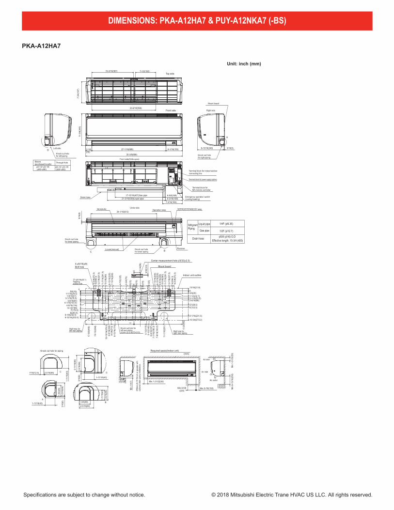
PKA-A12HA7
13
OUTLINES AND DIMENSIONS6
Unit: inch (mm)
1/2F ([12.7)
1/4F ([6.35)RefrigerantPiping
Drain hose
Gas pipe
Liquid pipe
[2-1/2~[3-1/8 ([65~[80)
[2-1/2~[3-1/8 ([65~[80)
Through holeSleeve(purchased locally)
Center measurement hole [3/32([2.5)
5/32
(3.8
)
2-1/
4(58
)
0
Wall hole forleft rear piping
Knock out hole forleft rear piping2-3/4×12-3/16(70×310) Wall hole for
right rear piping
77-[3/16([5.1)Tappingscrew hole
4-[5/16([9)Bolt hole Mount board
Indoor unit outline
05/8(16)
9-15/16(253.5)9-1/8(232.5)
1-1/16(28.5)1-9/16(41)
3-1/16(78.5)
4-1/16(103.5)4-9/16(116)6-1/2(166)
7(178.5)8(203.5)
3-9/16(91)
13/16(21.8)
9-1/16(231.5)
10-3/4(273.2)
0
1-1/4(32.7)
2-9/16(66)2-1/16(53.5)
5(128.5)6(153.5)
3/4(20)
9/16
(15)
14-5
/8(3
72.3
)14
(356
.3)
12-7
/8(2
37.5
)
11-7
/16(
291.
5)10
-3/8
(265
)9-
5/16
(238
)8-
13/1
6(22
5)7-
13/1
6(20
0)
4-7/
8(12
5)
2-3/
4(70
)
9/16
(15)
14-5
/8(3
72.3
)14
(356
.3)
12-7
/8(3
27.5
)
10-3
/8(2
65)
11-7
/16(
291.
5)
7-13
/16(
200)
8-13
/16(
225)
4-7/
8(12
5)
2-3/
4(70
)
0
17-5
/8(4
49)
7-9/
16(1
93.5
)7-
1/16
(180
.3)
6-9/
16(1
67)
5-1/
2(14
0)4-
1/2(
115)
6-13
/16(
174)
8-3/
8(21
3)9-
5/16
(238
)10
-15/
16(2
78.3
)
15-1
/2(3
94)
11-1
/16(
281)
17-5
/8(44
9)0
Emergency operation switch(cooling/heating)
Terminal block for MA-remote controller
Terminal block for power supply (option)
Front side(Grille open)
Terminal block for indoor/outdoorconnecting line
17-15/16(457)Gas pipe21-3/16(539)Liquid pipe
6-5/8(169)6-3/16(158)Drain hose
7-3/16(184)
250m
m,9
-13/
16in
ch o
r gre
ater
with
op
tiona
l dra
in p
ump
inst
alla
tion.
Required space(Indoor unit)(mm)
Air inlet
Air inlet
Air outlet
Min
.1-3
1/32
(50)
Min
.9-1
3/16
(250
)
Min.5-7/8(150)Min.8-5/8(220)
Min.1-31/32(50)
Min
.1/4
(7)
Knock out hole for piping
D
2-3/
16(5
6)
2-11
/16(
69)
3/16
(6)
1-11/16(43)
C2-3/16(56)7/16(12.5)
1-11
/16(
43)
B1-3/4(46)
2-5/16(60)
2-5/
16(5
9)
1-11
/16(
43)
A
1-11/16(43)
1-3/
4(46
)2-
3/16
(56)
3/16
(6)
A
Knock out holefor right piping
Right side
Mount board
3/16(5)9-13/16(249)
Top side15-3/16(387) 7-1/2(192)
7-3/
4(19
7)
23-9/16(599)
C B
Operation lamp DEFROST/STAND BY lamp
ReceiverLouver(manual)
Vane(auto)
Knock out holefor lower piping
Knock out holefor lower piping
Under side
5/16
(8) 24-1/16(612)
DKnock out holefor left piping
Left side
Front side
6-1/16(155)2-1/8(55)
27-1/16(688)
11-5
/8(2
95)
35-3/8(898)
[5/8 ([16) O.DEffective length: 15-3/4 (400)
DIMENSIONS: PKA-A12HA7 & PUY-A12NKA7 (-BS)
Specifications are subject to change without notice. © 2018 Mitsubishi Electric Trane HVAC US LLC. All rights reserved.
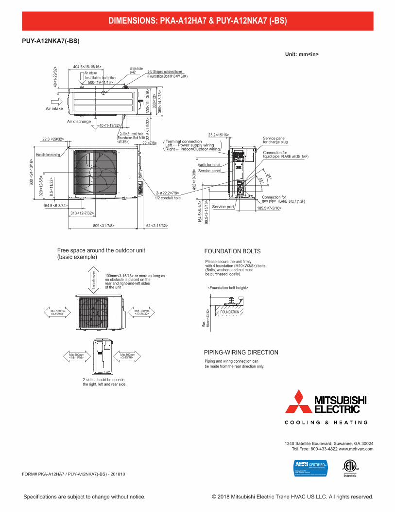
PUY-A12NKA7(-BS)
14
PUZ-A12NKA7 PUZ-A18NKA7 PUY-A12NKA7 PUY-A18NKA7PUZ-A12NKA7-BS PUZ-A18NKA7-BS PUY-A12NKA7-BS PUY-A18NKA7-BS
6 OUTLINES AND DIMENSIONS
1/2 conduit hole
144<5-21/32>
2-{22.2<7/8>
22<7/8>
38<1
-1/2
>24
1<9-
1/2>
Min.100mm<3-15/16>
Piping and wiring connection canbe made from the rear direction only.
*1 In the place where short cycle tends to occur, cooling and heating capacity and power consumption might get lowered 10%. Air outlet guide (optional PAC-SG58SG-E) will help them improve. *2 If air discharges to the wall, the surface might get stained.
2 sides should be open inthe right, left and rear side.
Min.100mm<3-15/16> as long as no obstacle is placed on therear and light-and-left sidesof the unit
*1*2 *1
Air intake
Air discharge4-oval hole
Air intake
Service panel
Connection for liquid pipe
Service panel for charge plug
Service port
Connection for gas pipe
Min.100mm<3-15/16>
Min.500mm<19-11/16>
Min.350mm<13-25/32>
Basi
cally
open
Max
.
<Foundation bolt height>
FOUNDATION
Please secure the unit firmlywith 4 foundation M10<W3/8> bolts.(Bolts, washers and nut must be purchased locally.)
18m
m<2
3/32
>
{33<1-5/16> drain hole
43.6
<1-2
3/32
>15
2<6>
155
400<15-25/32>
347.5<13-11/16>
45.4<1-25/32>
365<
14-3
/8>
330<
13>
300<
11-1
3/16
>
40<1-9/16>
Handle
600<
23-5
/8>
10<3
/8>
300<
11-1
3/16
>
150<5-29/32>287.5<11-11/32>
500<19-11/16>
800<31-1/2>
69<2-23/32>
183<7-7/32>
90<3
-17/
32>
155<
6-3/
32>
23<29/32>
32.5
<1-9
/32>
18<23/32>
FLARE {12.7<1/2>
FLARE {6.35<1/4>
Installation bolt pitch
PIPING-WIRING DIRECTION
Minimum installation space for outdoor unit
Free space around the outdoor unit(basic example)
FOUNDATION BOLTS
Unit: mm<in>
Air discharge
Air intake
Air intake
oval hole2-10×21
drain holeø 42 2-U Shaped notched holes
(Foundation Bolt M10<W 3/8>)
(Foundation Bolt M10<W 3/8>)
330<
13>
300<
11-1
3/16
>
40 <1-19/32>
404.5<15-15/16>
48<1
-29/
32>
360<
14-3
/16>
32.5
<1-9
/32>
500<19-11/16>
Min.500mm<19-11/16>
Min.100mm <3-15/16>
Service portFLARE 12.7 (1/2F)
Connection forgas pipe
FLARE ø
ø
6.35 (1/4F)Connection forliquid pipe
Service panelfor charge plug
Service panelEarth terminal
Terminal connectionLeft ... Power supply wiringRight ... Indoor/Outdoor wiring
23.2<15/16>
99.5
<3-1
5/16
>16
4.5<
6-1/
2>49
2<19
-3/8
>
185.5 <7-5/16>
43 °35 °
2-ø22.2<7/8>1/2 conduit hole
Installation bolt pitch
Handle for moving
22 <7/8>
320<
12-5
/8>
809 <31-7/8> 62 <2-15/32>
154.5 <6-3/32>
310 <12-7/32>
8.5<
11/3
2>
22.3 <29/32>
630
<24-
13/1
6>
Min.100mm<3-15/16>
Basic
ally
open
Min.350mm <13-25/32>
Max.
<Foundation bolt height>
18m
m<2
3/32
>
Free space around the outdoor unit(basic example)
100mm<3-15/16> or more as long asno obstacle is placed on therear and right-and-left sidesof the unit
2 sides should be open in the right, left and rear side.
Please secure the unit firmlywith 4 foundation (M10<W3/8>) bolts.(Bolts, washers and nut must be purchased locally).
FOUNDATION BOLTS
Piping and wiring connection canbe made from the rear direction only.
PIPING-WIRING DIRECTION
FOUNDATION
OCH636
FORM# PKA-A12HA7 / PUY-A12NKA7(-BS) - 201810
1340 Satellite Boulevard, Suwanee, GA 30024Toll Free: 800-433-4822 www.mehvac.com
DIMENSIONS: PKA-A12HA7 & PUY-A12NKA7 (-BS)
Specifications are subject to change without notice. © 2018 Mitsubishi Electric Trane HVAC US LLC. All rights reserved.

![Job Name: PUY-A24NHA7-BS - MyLinkDrivemeus1.mylinkdrive.com/files/PKA-A24KA7___PUY-A24NHA7-BS_Prod… · 3-Pole Disconnect Switch (30A/600V/UL) [fits 2" X 4" utility box] TAZ-MS303](https://static.fdocuments.in/doc/165x107/5ad849be7f8b9a865b8d3684/job-name-puy-a24nha7-bs-3-pole-disconnect-switch-30a600vul-fits-2-x-4.jpg)


![Job Name: PUY-A12NKA7-BS - MyLinkDrivemeus1.mylinkdrive.com/...A12HA7___PUY-A12NKA7-BS_Product_Data… · 3-Pole Disconnect Switch (30A/600V/UL) [fits 2" X 4" utility box] TAZ-MS303](https://static.fdocuments.in/doc/165x107/5b84951e7f8b9a784a8c97a1/job-name-puy-a12nka7-bs-3-pole-disconnect-switch-30a600vul-fits-2-x.jpg)