Status and Progress of a Fault Current Limiting HTS...
29
solutions Status and Progress of a Fault Current Limiting HTS Cable To Be Installed In The Consolidated Edison Grid J. Yuan, J. Maguire, D. Folts, N. Henderson, American Superconductor D. Knoll, Southwire M. Gouge, R. Duckworth, J. Demko, ORNL Z. Wolff ,Consolidated Edison Tenth EPRI Superconductivity Conference October 11-13, 2011 Tallahassee, FL
Transcript of Status and Progress of a Fault Current Limiting HTS...

solutions
Status and Progress of a Fault Current Limiting HTS Cable To Be Installed
In The Consolidated Edison Grid
J. Yuan, J. Maguire, D. Folts, N. Henderson, American Superconductor
D. Knoll, Southwire
M. Gouge, R. Duckworth, J. Demko, ORNL
Z. Wolff ,Consolidated Edison
Tenth EPRI Superconductivity Conference
October 11-13, 2011
Tallahassee, FL

solutions
Outline
• Hydra Project Overview
- Specification
- Team roles and responsibility
- Main goals and objectives
• Fault Current Limiting Cable Operation Principle
• FCL Cable System Components
• 3m & 25m Prototype Cable Test Results
• Refrigeration System
• Conclusions

solutions
HYDRA Project Overview
World’s First FCL Distribution Cable to be Installed in Operating Grid
• Consolidated Edison’s Substations
• Electrical Characteristics
- Design Voltage/Current – 13.8kV, 4,000 amp ~96MVA
- Design Fault Current – 40kA @ 67ms
• Physical Characteristics
- Length ~ 170m
- HTS Conductor Length ~50km
- Cold Dielectric, Triax Design
• Hardware Deliverables
- One ~170m Long, 3 Phase HTS Cable
- Two 13.8kV Outdoor Terminations
- One Refrigeration System
• Commissioning – Summer 2014

solutions
Team Roles and Responsibilities
DHS
Science &
Technology
Directorate
AMSC
Prime
Contractor
ORNL
Test Agency
DH
Industries
Ultera
Altran
Solutions
Consolidated
Edison
AMSC
System
Design
Wire
Development
Project
Management
Wire
Manufacturing
Technical
Oversight
Utility
Requirements
Construction
Management
System Hardware
Development
System
Planning
Cooling
System
Installation
Support
Site
Design
Permitting
Civil
Work
O&M
Contract
Cable & Accessory
Design
Cable & Accessory
Installation
Cable
Manufacturing
25m Prototype
Cable Test Site
Technical
Support

solutions
HYDRA Project Main Objectives
• Demonstrate High Temperature Superconductor Fault
Current Limiting Link Between Substations
• Demonstrate Feasibility of an Installation of a Fault Current
Limiting HTS System in Population-Condensed Urban Area
• Demonstrate an Installation and Operation of a Reliable
Cryogenic System

solutions
Fault Current Limiting Cable Operation Principal
Simplified View of Superconductor wire
high resistance layer
zero resistance superconductor layer
switched high resistance superconductor layer
high resistance layer
• Superconductor wire has zero resistance up to the “critical” current
Load Current
Fault Current
Allows the construction of fault current limiting cables
• AMSC supplies a superconductor wire that instantlyintroduces high resistance above the critical current
• Immediate limitation of fault current magnitudes
• Insertion of resistance decreases X/R and fault asymmetry

solutions
Paralleling Urban Buses: The Appeal
Advantages of Paralleled Substations – Simple Case
• Connect additional load without additional transformers or new substations
• Increases transformer asset utilization
• Reduces cost of N-1 contingency planning; only 1 transformer required versus
2
• Increased interconnectivity protects vulnerable, critical loads in the event of a
catastrophic failure
Typical 2-transformer
urban substations
Paralleling Dense Urban Load Centers Leads to Operational Efficiencies
Total Load ≤60% total transformer MVA Total Load ≤60% total transformer MVATypical
Loading
Practice
solutions
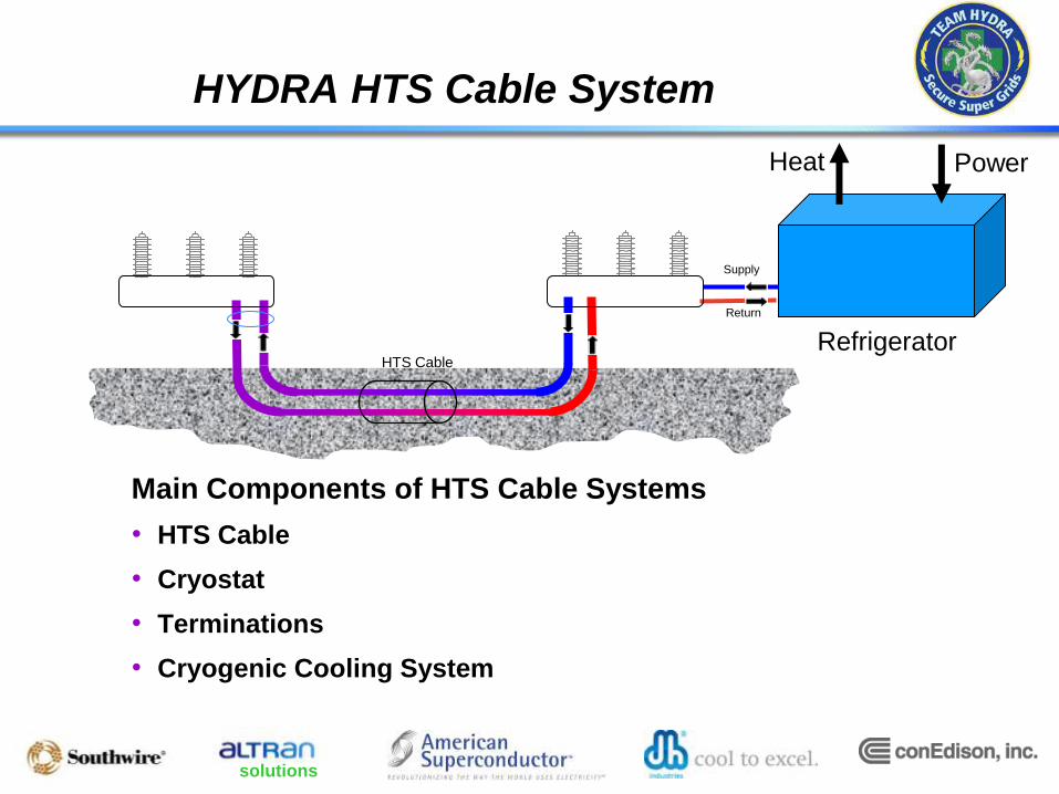
HYDRA HTS Cable System
Power
Supply
Return
Refrigerator
Heat
HTS Cable
Main Components of HTS Cable Systems
• HTS Cable
• Cryostat
• Terminations
• Cryogenic Cooling System

solutions
Components of the HTS Cable System
• Superconducting Cable System
- Cable Core
• Transport the current
• Limit the fault current
• Withstand the voltage
- Cryostat
• Insulate thermally – keep the cable
cold
• Transport the liquid nitrogen
- Termination
• Connect the system to the grid
• Manage the transition between cold
temperature and room temperature
• Provide connection to the cooling
system

solutions
Cable Design- Triax® by Southwire
CryostatFormer
Phase 1 Superconductor
Dielectric
Phase 2 SuperconductorDielectric
Phase 3 Superconductor
Dielectric
Copper Neutral
Photo courtesy of Ultera
Triax is a trademark of Southwire
Supply LN2
solutions
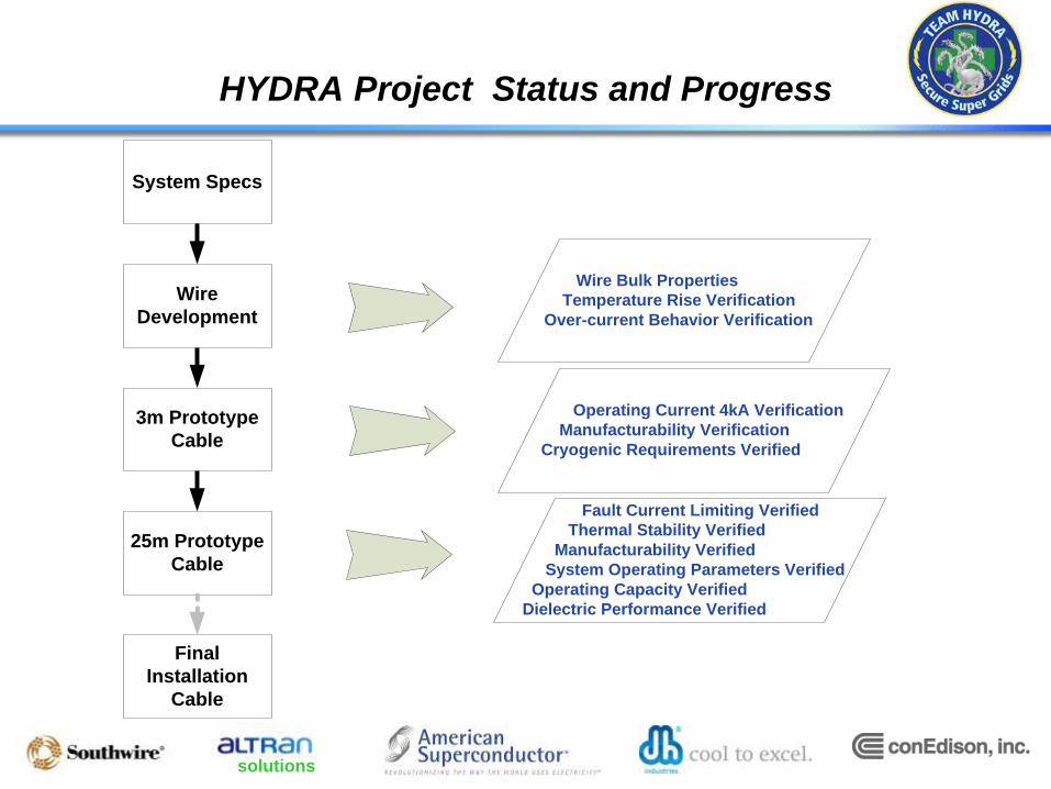
HYDRA Project Status and Progress
Wire
Development
System Specs
3m Prototype
Cable
25m Prototype
Cable
Final
Installation
Cable
Wire Bulk Properties
Temperature Rise Verification
Over-current Behavior Verification
Operating Current 4kA Verification
Manufacturability Verification
Cryogenic Requirements Verified
Fault Current Limiting Verified
Thermal Stability Verified
Manufacturability Verified
System Operating Parameters Verified
Operating Capacity Verified
Dielectric Performance Verified

solutions
3m Cable Let-Through Tests
• Three 9.1kA 270ms shots
- ~20min apart
- Three faults within one hour
• Results
- Cable is superconducting throughout the current surge
- No evident heating observed

solutions
3m Cable FCL Test Conclusions
• The cable is superconducting after the tests
• No change in temperature seen in 9.1kArms 270ms thru
fault tests
• Less than 1K in temperature rise in 7.2kArms 2000ms
thru fault tests.
• Current limiting capability is evident
- Prospective current of 60kArms limited to 30kArms
- Cable voltage is 8Vpeak / m at first cycle and 11Vpeak/ m at last
cycle

solutions
25m Prototype Cable Test Setup
Termination
25m HTS Triax® Cable
Refrigeration system

solutions
25m Cable Test LN2 Flow Diagram
Subcooler
V1V2V3
V4V5
LN2 Pump
Triax HTS
Cable
Termination
Termination

solutions
25m Cable Test Plan
25m Prototype
Cable Tests
Dielectric
Tests
Performance
Characteristics
Thermal
Tests
Other
Tests
Cable
Resistance
DC Critical
Current
AC
Loss
FCL
Low Voltage
FCL
High Voltage
Thermal
Stability
Thermal
Cycle
Voltage
Soak
Partial
Discharge
AC
Withstand
Lightning
Impulse
Post-BIL
Partial
Discharge
AC
Withstand
Leak
Check
Post BIL&
FCL DC Ic
Post Thermal
Cycle DC Ic

solutions
25-m HTS Cable Ic Tests
25-m Cable Ic
5000
5500
6000
6500
7000
7500
8000
8500
9000
73 74 75 76 77 78 79
Temperature (K)
Cri
tic
al
Cu
rre
nt
(A)
Phase 1
Phase 2
Phase 3
Requirements of phase conductor Ic at 77.3K

solutions
Stability Test
71.8
72.0
72.2
72.4
72.6
72.8
73.0
73.2
73.4
73.6
73.8
74.0
74.2
74.4
0.00 5.00 10.00 15.00 20.00 25.00 30.00
time (hr)
Te
mp
era
ture
(K
)
108.0
110.0
112.0
114.0
116.0
118.0
120.0
122.0
124.0
126.0
128.0
130.0
132.0
134.0
Ca
ble
Pre
ss
ure
(p
si)
TE118
TE119
PT100
refrigerator return temperature
refrigerator supply temperature
cable pressure
4000Arms was applied

solutions
AC Loss
0.00
1.00
2.00
3.00
4.00
5.00
6.00
7.00
8.00
9.00
0 1000 2000 3000 4000 5000
3 p
has
e A
C lo
ss (
W/m
)
Current (Arms)
72K

solutions
FCL Test
Measured versus Simulated Results
Symmetrical Fault
-80
-70
-60
-50
-40
-30
-20
-10
0
10
20
30
40
50
60
70
80
0.0000 0.0083 0.0167 0.0250 0.0333 0.0417 0.0500 0.0583 0.0667 0.0750 0.0833 0.0917 0.1000
Time (S)
Cu
rre
nt
(kA
)
Measured Limited Current (kA)
Meas Unlimited Current
Simulated Limited Current (kA)
Measured & Simulated
Limited Current
Unlimited Fault Current
solutions
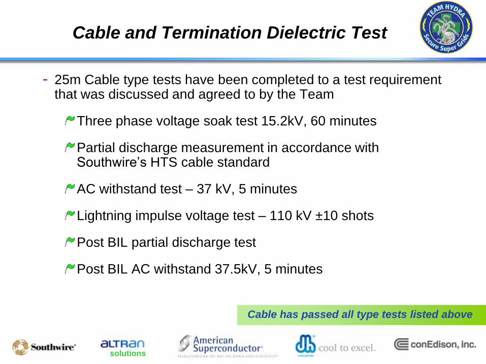
Cable and Termination Dielectric Test
- 25m Cable type tests have been completed to a test requirement that was discussed and agreed to by the Team
Three phase voltage soak test 15.2kV, 60 minutes
Partial discharge measurement in accordance with Southwire’s HTS cable standard
AC withstand test – 37 kV, 5 minutes
Lightning impulse voltage test – 110 kV ±10 shots
Post BIL partial discharge test
Post BIL AC withstand 37.5kV, 5 minutes
Cable has passed all type tests listed above
solutions
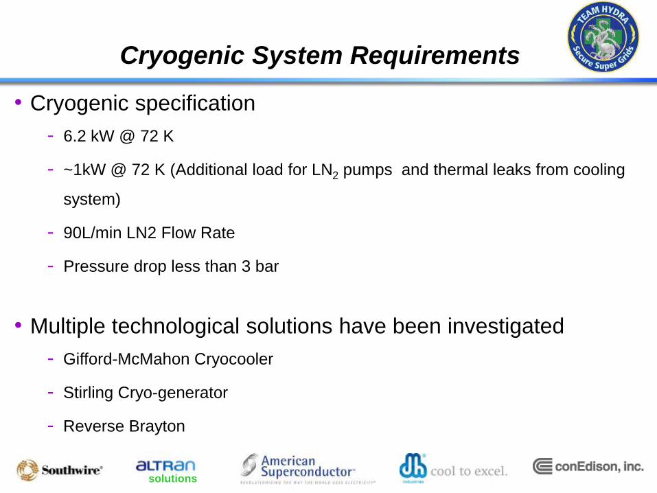
Cryogenic System Requirements
• Cryogenic specification
- 6.2 kW @ 72 K
- ~1kW @ 72 K (Additional load for LN2 pumps and thermal leaks from cooling
system)
- 90L/min LN2 Flow Rate
- Pressure drop less than 3 bar
• Multiple technological solutions have been investigated
- Gifford-McMahon Cryocooler
- Stirling Cryo-generator
- Reverse Brayton

solutions
Refrigerator Requirements
• Refrigeration Cycle chosen is Stirling Cryo-generator
- Modulated design (3 x 4kW @ 77K)
- Best return on specific efficiency (We/Wc) vs. capital cost
• Flexibility Requirement:
- 80% of time at 50% heat load on HTS cable
• Reliability
- Redundancy accomplished at component level, pumps
- No 1st order single point of failure allowed
• Capacity Margin
- Current design has 20% safety margin to the expected losses

solutions
Refrigeration System Diagram
- Estimated foot print size & weight
• 11.6 m x 9 m ( 38’ x 30’ ) + outdoor
water chiller
• ~ 15 000 kg ( 33 000 lbs ) empty
• Fits within available space
Subcooler
V1
V2
V3 V4V5
LN2 Pump
~170m Triax HTS CableTermination
Termination
Primary
Cooler
Back-up
Cooler
Buffer Tank

solutions
Accomplishments to Date
The key invention has been demonstrated
• Demonstration of the Fault Current Limiting aspects of 2G
wire and the cable design
• Exceptionally good agreement between Fault Current
Limiting model predictions and measured performance in
25 meter cable demonstration
• The HTS FCL Cable successfully passed all the
qualification tests for installation in the power grid
solutions
Conclusions
• American Superconductor and the project team are demonstrating
significant progress toward the development of a long length fault
current limiting superconducting cable for integration into the
Consolidated Edison grid.
• Short cable tests demonstrated the current limiting capability
• 25m cable and termination type tests have been successfully
completed.
• Cable manufacturing process has been approved
• A 170m long HTS cable with fault current limiting functionality is
planned to connect two of Con Edison’s substations in late 2014.

solutions
Acknowledgment: This material is based upon work supported by the Department of Homeland Security, Science & Technology Directorate, under contract #HSHQDC-08-9-00001.
Disclaimer: This report was prepared as an account of work sponsored by an agency of the United States Government. Neither the United States Government nor any agency thereof, nor any of their employees, makes any warranty, express or implied, or assumes any legal liability or responsibility for the accuracy, completeness, or usefulness of any information, apparatus, product, or process disclosed, or represents that its use would not infringe privately owned rights. Reference herein to any specific commercial product, process, or service by trade name, trademark, manufacturer, or otherwise does not necessarily constitute or imply its endorsement, recommendation, or favoring by the United States Government or any agency thereof. The views and opinions of authors expressed herein do not necessarily state or reflect those of the United States Government or any agency thereof.