Hydra Fault Current Limiting HTS Cable to be Installed...
27
solutions Hydra Fault Current Limiting HTS Cable to be Installed in the Consolidated Edison Grid J. McCall, J. Yuan, D. Folts, N. Henderson, American Superconductor D. Knoll, Southwire M. Gouge, R. Duckworth, J. Demko, ORNL Z. Wolff, S. Sagareli, Y. Abouyaala, Consolidated Edison 11th EPRI Superconductivity Conference October 28-30, 2013 Houston, TX
Transcript of Hydra Fault Current Limiting HTS Cable to be Installed...

solutions
Hydra Fault Current Limiting HTS Cable
to be Installed in the Consolidated Edison Grid
J. McCall, J. Yuan, D. Folts, N. Henderson, American Superconductor
D. Knoll, Southwire
M. Gouge, R. Duckworth, J. Demko, ORNL
Z. Wolff, S. Sagareli, Y. Abouyaala, Consolidated Edison
11th EPRI Superconductivity Conference
October 28-30, 2013
Houston, TX

solutions
Outline
• Hydra Project Primary Objectives
• Hydra Project Overview
• Fault Current Limiting Cable Operation Principles
• Paralleling Urban Buses
• FCL Cable System Components
• 25m Prototype Cable Test Results
• Phase 1 Achievements
• Phase 2 Status
• Hydra Project Summary

solutions
Hydra Project Primary Objectives
• Develop and Demonstrate Fault Current Limiting HTS
Cable to protect critical urban power network
infrastructure
• Phase 1- Develop inherently Fault Current Limiting
Cable design - Passed all Industry Qualification tests and engineering studies
- Con Edison approved for installation in urban power network
• Phase 2- System design, installation and 1-year
operational demonstration - Site design, construction permitting and system design underway
- Operation connecting two Con Edison 13.8kV substations
solutions
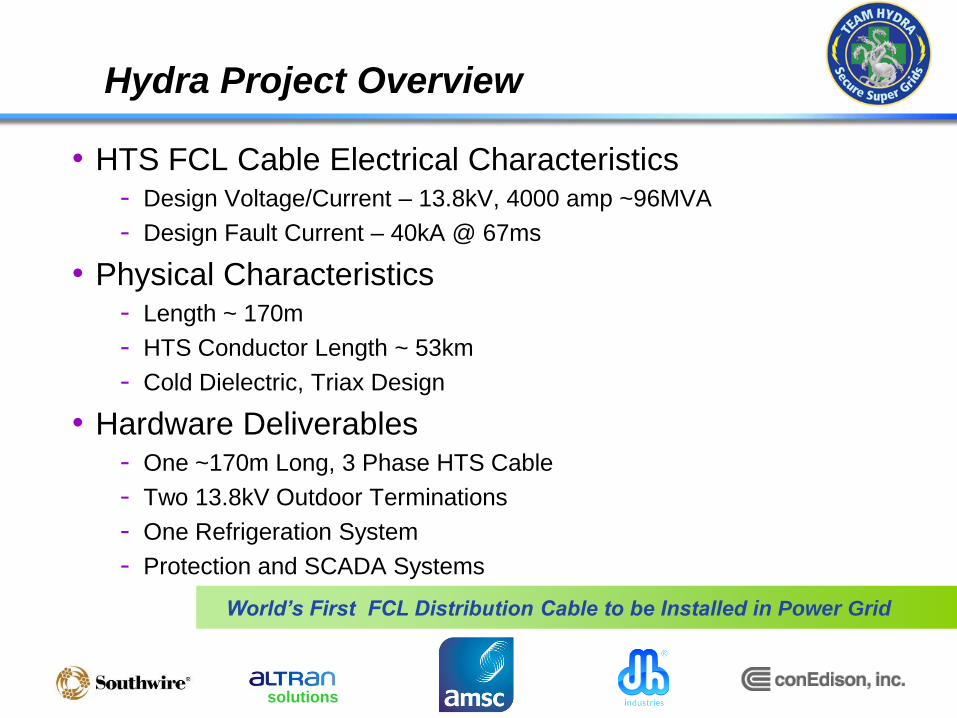
Hydra Project Overview
World’s First FCL Distribution Cable to be Installed in Power Grid
• HTS FCL Cable Electrical Characteristics - Design Voltage/Current – 13.8kV, 4000 amp ~96MVA
- Design Fault Current – 40kA @ 67ms
• Physical Characteristics - Length ~ 170m
- HTS Conductor Length ~ 53km
- Cold Dielectric, Triax Design
• Hardware Deliverables - One ~170m Long, 3 Phase HTS Cable
- Two 13.8kV Outdoor Terminations
- One Refrigeration System
- Protection and SCADA Systems
solutions
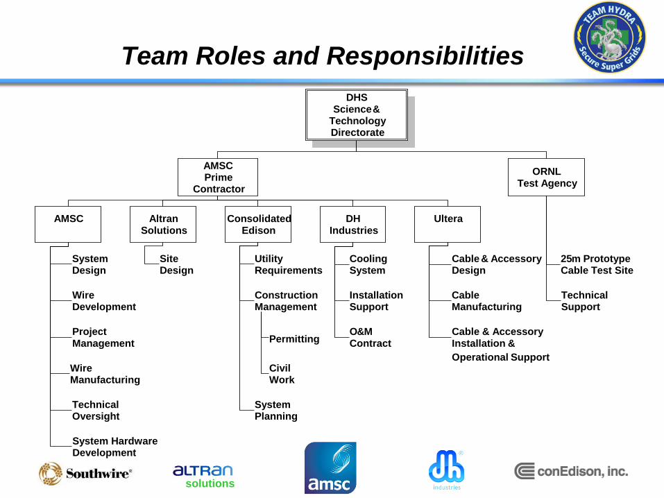
Team Roles and Responsibilities
DHS Science &
Technology Directorate
AMSC Prime
Contractor
ORNL Test Agency
DH Industries
Ultera
Altran Solutions
Consolidated Edison
AMSC
System Design
Wire Development
Project Management
Wire Manufacturing
Technical Oversight
Utility Requirements
Construction Management
System Hardware Development
System Planning
Cooling System
Installation Support
Site Design
Permitting
Civil Work
O & M Contract
Cable & Accessory Design
Cable & Accessory
Operational Support
Installation &
Cable Manufacturing
25 m Prototype Cable Test Site
Technical Support
solutions
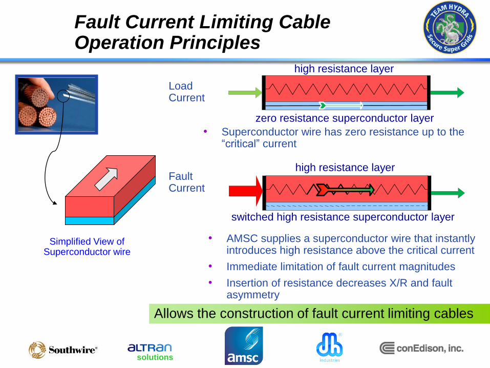
Fault Current Limiting Cable Operation Principles
Simplified View of Superconductor wire
high resistance layer
zero resistance superconductor layer
switched high resistance superconductor layer
high resistance layer
• Superconductor wire has zero resistance up to the “critical” current
Load Current
Fault Current
Allows the construction of fault current limiting cables
• AMSC supplies a superconductor wire that instantly introduces high resistance above the critical current
• Immediate limitation of fault current magnitudes
• Insertion of resistance decreases X/R and fault asymmetry

solutions
Paralleling Urban Buses: The Appeal
Advantages of Paralleled Substations – Simple Case
• Connect additional load without additional transformers or new substations
• Increases transformer asset utilization
• Reduces cost of N-1 contingency planning; only 1 transformer required versus 2
• Increased interconnectivity protects vulnerable, critical loads in the event of a
catastrophic failure
Typical 2-transformer
urban substations
Paralleling Dense Urban Load Centers Leads to Operational Efficiencies
Total Load ≤60% total transformer MVA Total Load ≤60% total transformer MVA
Typical
Loading
Practice

solutions
Rockview Area Substation
T3
Granite Hill Area Substation
General Electrical Configuration (Existing)
G5
Step-down Transformer
Circuit Breaker
Power flow
13.8 kV Distribution to Yonkers Customers
13.8 kV Distribution to Yonkers Customers
138 kV Transmission
solutions
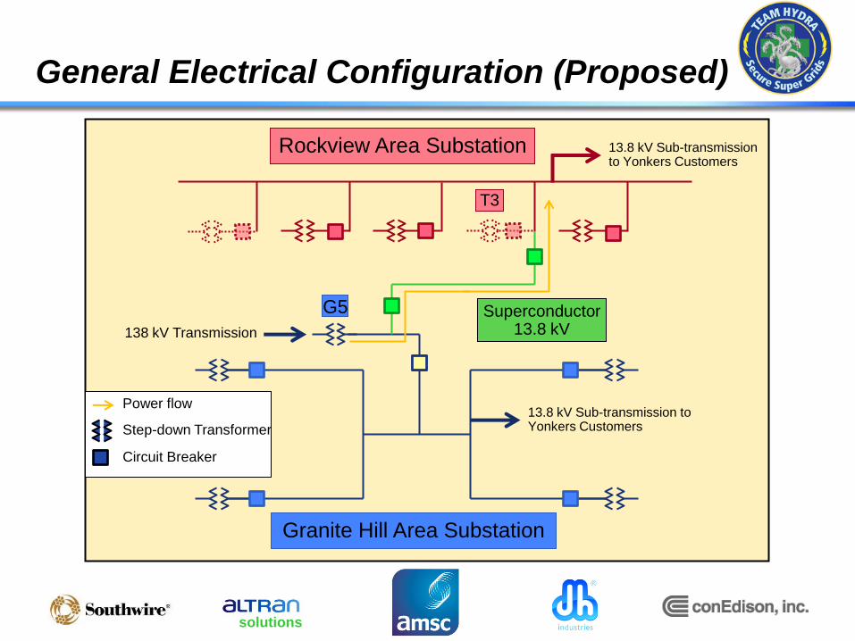
Rockview Area Substation
T3
Granite Hill Area Substation
General Electrical Configuration (Proposed)
Superconductor 13.8 kV
G5
138 kV Transmission
Step-down Transformer
Circuit Breaker
13.8 kV Sub-transmission to Yonkers Customers
13.8 kV Sub-transmission to Yonkers Customers
Power flow
solutions
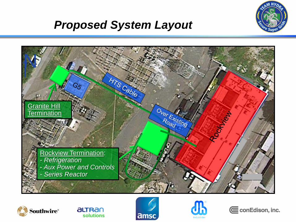
Proposed System Layout
Rockview Termination: - Refrigeration - Aux Power and Controls - Series Reactor
Granite Hill Termination
N

solutions
Hydra HTS Cable System
Power
Supply
Return
Refrigerator
Heat
HTS Cable
Main Components of HTS Cable Systems
• HTS Cable
• Cryostat
• Terminations
• Cryogenic Cooling System

solutions
Components of the HTS Cable System
• Superconducting Cable System
- Cable Core
• Transport the current
• Limit the fault current
• Withstand the voltage
- Cryostat
• Insulate thermally – keep the cable
cold
• Transport the liquid nitrogen
- Termination
• Connect the system to the grid
• Manage the transition between cold
temperature and room temperature
• Provide connection to the cooling
system

solutions
Cable Design - Triax® by Southwire
Cryostat Former
Phase 1 Superconductor
Dielectric
Phase 2 Superconductor Dielectric
Phase 3 Superconductor
Dielectric
Copper Neutral
Photo courtesy of Ultera
Triax is a trademark of Southwire
Supply LN2

solutions
25m HTS Prototype Cable Test Setup
Termination
25m HTS Triax® Cable
Refrigeration system

solutions
25m HTS Cable Test LN2 Flow Diagram
Subcooler
V1V2V3
V4V5
LN2 Pump
Triax HTS
Cable
Termination
Termination
solutions
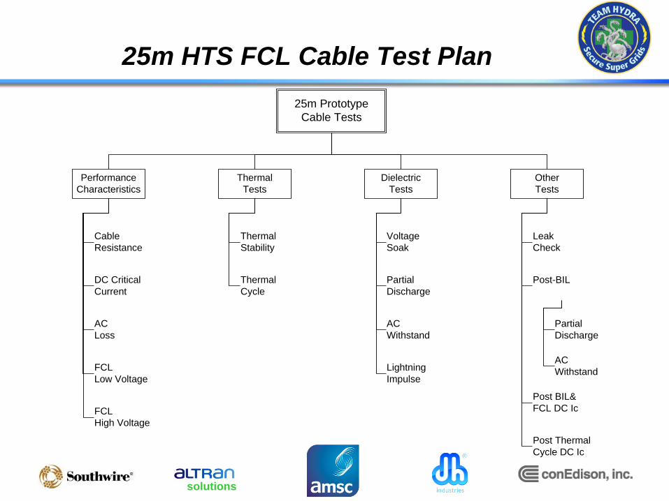
25m HTS FCL Cable Test Plan
25m Prototype
Cable Tests
Dielectric
Tests
Performance
Characteristics
Thermal
Tests
Other
Tests
Cable
Resistance
DC Critical
Current
AC
Loss
FCL
Low Voltage
FCL
High Voltage
Thermal
Stability
Thermal
Cycle
Voltage
Soak
Partial
Discharge
AC
Withstand
Lightning
Impulse
Post-BIL
Partial
Discharge
AC
Withstand
Leak
Check
Post BIL&
FCL DC Ic
Post Thermal
Cycle DC Ic
solutions
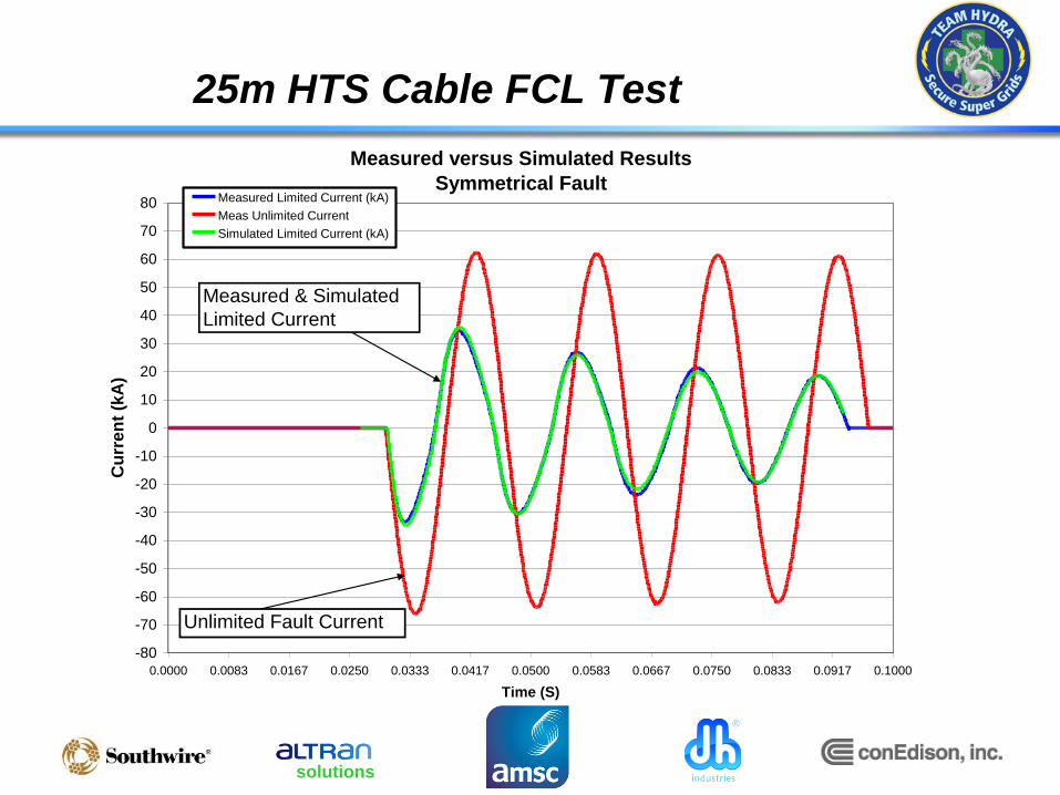
25m HTS Cable FCL Test
Measured versus Simulated Results
Symmetrical Fault
-80
-70
-60
-50
-40
-30
-20
-10
0
10
20
30
40
50
60
70
80
0.0000 0.0083 0.0167 0.0250 0.0333 0.0417 0.0500 0.0583 0.0667 0.0750 0.0833 0.0917 0.1000
Time (S)
Cu
rre
nt
(kA
)
Measured Limited Current (kA)
Meas Unlimited Current
Simulated Limited Current (kA)
Measured & Simulated
Limited Current
Unlimited Fault Current

solutions
25m Cable and Termination Dielectric Tests
- 25m Cable type tests have been completed to a test requirement that was discussed and agreed to by the Team
Three phase voltage soak test 15.2kV, 60 minutes
Partial discharge measurement in accordance with Southwire’s HTS cable standard
AC withstand test – 37.5 kV, 5 minutes
Lightning impulse voltage test – ±110 kV, 10 shots
Post BIL partial discharge test
Post BIL AC withstand 37.5kV, 5 minutes
Cable has passed all type tests listed above

solutions
Hydra Project Phase 1 Achievements
Wire
Development
System Specs
3m Prototype
Cable
25m Prototype
Cable
HTS FCL Cable Qualified for
Power Network
Wire Bulk Properties Verified
Temperature Rise Verified
Over-current Behavior Verified
Operating Current 4kA Verified
Manufacturability Verified
Refrigeration Requirements Verified
Fault Current Limiting Verified
Thermal Stability Verified
Manufacturability Verified
System Operating Parameters Verified
Operating Capacity Verified
Dielectric Performance Verified
FCL Performance Verified
Engineering Models Validated
Passed Industry Qualification Tests
Con Edison approved for installation
between two urban substations

solutions
Hydra Project Phase 2 Status
• HTS FCL Cable installation site selected in Westchester
County connecting two 13.8kV substations
• HTS FCL Cable will allow asset sharing of 13.8 kV
transformer combined with fault current protection to
equipment
• First-of-kind grid architecture requires new approach to
relay protection and tap changer controls
• Site design and construction permitting progressing
• Equipment procurement and manufacture underway
• System control design and integration on-going

solutions
Hydra HTS FCL Cable Manufacture
• AMSC provided 53km of
HTS FCL wire to Southwire
• Southwire/nkt cables
(“Ultera”) manufacture of
HTS FCL Cable underway
• Cable installation plan in
process
• Cable termination materials
on order for integration with
cable assembly at
substations
25m HTS TriaxTM FCL cable
Full Scale Terminations
solutions
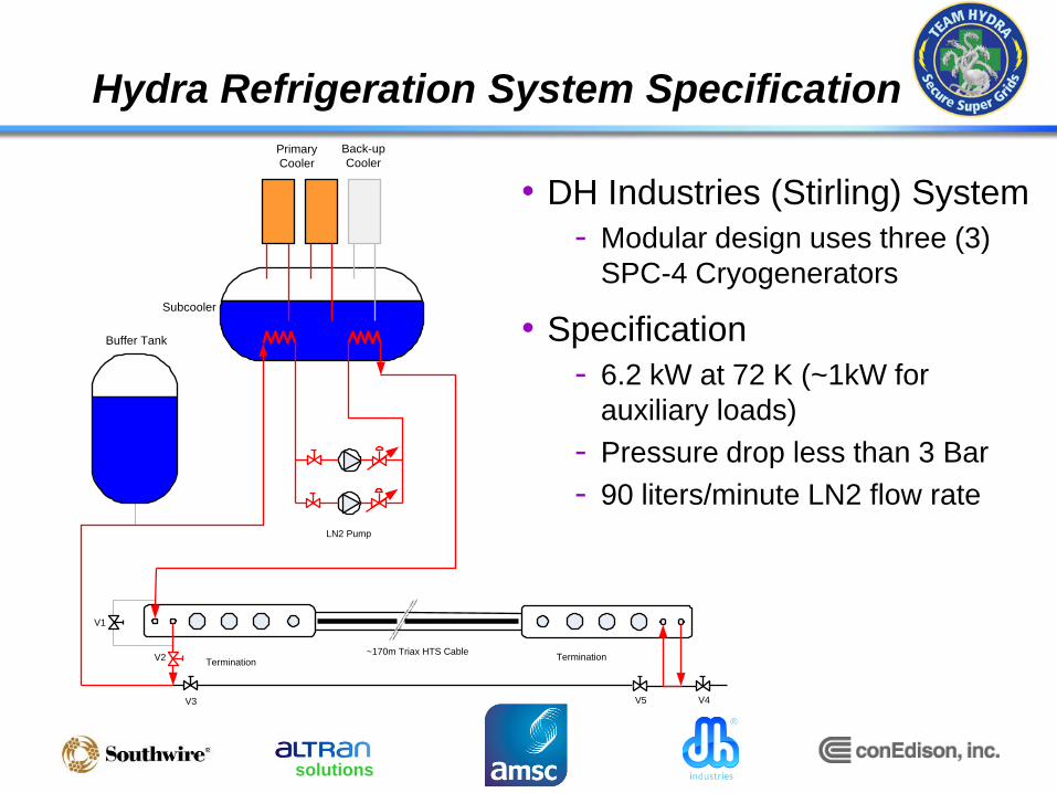
Subcooler
V1
V2
V3 V4V5
LN2 Pump
~170m Triax HTS CableTermination
Termination
Primary
Cooler
Back-up
Cooler
Buffer Tank
• DH Industries (Stirling) System
- Modular design uses three (3)
SPC-4 Cryogenerators
• Specification
- 6.2 kW at 72 K (~1kW for
auxiliary loads)
- Pressure drop less than 3 Bar
- 90 liters/minute LN2 flow rate
Hydra Refrigeration System Specification

solutions
Hydra Refrigeration System Manufacture
• Reliability - Redundancy accomplished at component
level (modular design)
- No first-order single points of failure
allowed
- Designed with 20% safety margin to the
expected losses
• Manufacture - Electrical design and fabrication completed
- Vessels and vacuum-jacketed lines being
manufactured
- Assembly and factory testing in early 2014

solutions
Hydra Project Summary
• HTS FCL Cable passed all Industry Qualification tests
• 25 meter cable test results validated FCL performance
model predictions
• Equipment procurement and manufacture progressing
• Below grade construction package out for bid
• Construction expected to start in early 2014, followed by
equipment installation and commissioning tests
• Operational demonstration will connect two Con Edison
substations enabling 13.8kV asset sharing in the power
network

solutions
Acknowledgment: This material is based upon work supported by the Department of Homeland Security, Science & Technology Directorate, under contract #HSHQDC-08-9-00001. Disclaimer: This report was prepared as an account of work sponsored by an agency of the United States Government. Neither the United States Government nor any agency thereof, nor any of their employees, makes any warranty, express or implied, or assumes any legal liability or responsibility for the accuracy, completeness, or usefulness of any information, apparatus, product, or process disclosed, or represents that its use would not infringe privately owned rights. Reference herein to any specific commercial product, process, or service by trade name, trademark, manufacturer, or otherwise does not necessarily constitute or imply its endorsement, recommendation, or favoring by the United States Government or any agency thereof. The views and opinions of authors expressed herein do not necessarily state or reflect those of the United States Government or any agency thereof.