
Stability management of high speed axial flow compressor ...
14
HOSTED BY ORIGINAL ARTICLE Stability management of high speed axial flow compressor stage through axial extensions of bend skewed casing treatment Dilipkumar Bhanudasji Alone a,n , S. Satish Kumar a , Shobhavathy M. Thimmaiah a , Janaki Rami Reddy Mudipalli a , A.M. Pradeep b , Srinivasan Ramamurthy c , Venkat S. Iyengar a a Propulsion Division, CSIR-NAL, Bangalore 560037, India b Aerospace Engineering Department, IIT Bombay, Powai 400076, India c NCAD, CSIR-NAL, Bangalore 560017, India Received 24 November 2014; accepted 5 January 2016 Available online 12 September 2016 KEYWORDS High speed compressor; Bend skewed casing treatments; Axial extensions; Stall margin improve- ments; Peak stage efficiency; Hot wire probe; Stall; Abrupt Abstract This paper presents the experimental results to understand the performance of moderately loaded high speed single stage transonic axial flow compressor subjected to various configurations of axial extensions of bend skewed casing treatment with moderate porosity. The bend skewed casing treatment of 33% porosity was coupled with rectangular plenum chamber of depth equal to the slots depth. The five axial extensions of 20%, 40%, 60%, 80% and 100% were used for the experimental evaluations of compressor performance. The main objective was to identify the optimum extension of the casing treatment with reference to rotor leading edge which results in maximum stall margin improvements with minimum loss in the stage efficiency. At each axial extension the compressor performance is distinctive. The improvement in the stall margin was very significant at some axial extensions with 4%–5% penalty in the stage efficiency. The compressors stage shows recovery in terms of efficiency at lower axial extensions of 20% and 40% with increase in the peak stage efficiency. Measurements of flow parameters showed the typical behaviors at near stall flow conditions. Hot wire sensor was placed at the rotor upstream in the tip region to capture the oscillations in the inlet axial and tangential velocities at stall conditions. In the absence of casing treatment the compressor exhibit abrupt stall with very high oscillations in the http://ppr.buaa.edu.cn/ www.sciencedirect.com Propulsion and Power Research 2212-540X & 2016 National Laboratory for Aeronautics and Astronautics. Production and hosting by Elsevier B.V. This is an open access article under the CC BY-NC-ND license (http://creativecommons.org/licenses/by-nc-nd/4.0/). http://dx.doi.org/10.1016/j.jppr.2016.01.009 n Corresponding author. Tel.: +9180 25051527. E-mail address: [email protected] (Dilipkumar Bhanudasji Alone). Peer review under responsibility of National Laboratory for Aeronautics and Astronautics, China. Propulsion and Power Research 2016;5(3):236–249
Transcript of Stability management of high speed axial flow compressor ...
http://ppr.buaa.edu.cn/
H O S T E D B Ywww.sciencedirect.com
Propulsion and Power Research
Propulsion and Power Research 2016;5(3):236–249
2212-540X & 2016 NaCC BY-NC-ND licens
http://dx.doi.org/10.10
nCorresponding aut
E-mail address: dil
Peer review under rand Astronautics, Chin
ORIGINAL ARTICLE
Stability management of high speed axial flowcompressor stage through axial extensions of bendskewed casing treatment
DilipkumarBhanudasji Alonea,n, S. Satish Kumara, Shobhavathy M. Thimmaiaha,Janaki Rami Reddy Mudipallia, A.M. Pradeepb, Srinivasan Ramamurthyc,Venkat S. Iyengara
aPropulsion Division, CSIR-NAL, Bangalore 560037, IndiabAerospace Engineering Department, IIT Bombay, Powai 400076, IndiacNCAD, CSIR-NAL, Bangalore 560017, India
Received 24 November 2014; accepted 5 January 2016Available online 12 September 2016
KEYWORDS
High speedcompressor;Bend skewed casingtreatments;Axial extensions;Stall margin improve-ments;Peak stage efficiency;Hot wire probe;Stall;Abrupt
tional Laboratory foe (http://creativecom
16/j.jppr.2016.01.00
hor. Tel.: +9180 25
esponsibility of Natia.
Abstract This paper presents the experimental results to understand the performance ofmoderately loaded high speed single stage transonic axial flow compressor subjected to variousconfigurations of axial extensions of bend skewed casing treatment with moderate porosity. Thebend skewed casing treatment of 33% porosity was coupled with rectangular plenum chamber ofdepth equal to the slots depth. The five axial extensions of 20%, 40%, 60%, 80% and 100% wereused for the experimental evaluations of compressor performance. The main objective was toidentify the optimum extension of the casing treatment with reference to rotor leading edge whichresults in maximum stall margin improvements with minimum loss in the stage efficiency. At eachaxial extension the compressor performance is distinctive. The improvement in the stall margin wasvery significant at some axial extensions with 4%–5% penalty in the stage efficiency. Thecompressors stage shows recovery in terms of efficiency at lower axial extensions of 20% and 40%with increase in the peak stage efficiency. Measurements of flow parameters showed the typicalbehaviors at near stall flow conditions. Hot wire sensor was placed at the rotor upstream in the tipregion to capture the oscillations in the inlet axial and tangential velocities at stall conditions. In theabsence of casing treatment the compressor exhibit abrupt stall with very high oscillations in the
r Aeronautics and Astronautics. Production and hosting by Elsevier B.V. This is an open access article under themons.org/licenses/by-nc-nd/4.0/).
9
051527.
(Dilipkumar Bhanudasji Alone).
onal Laboratory for Aeronautics

Stability management of high speed axial flow compressor stage through axial extensions of bend skewed casing treatment 237
inlet axial and tangential velocity of the flow. The extents of oscillations reduce with bend skewedcasing treatment. Few measurements were also performed in the plenum chamber and salientresults are presented in this paper.& 2016 National Laboratory for Aeronautics and Astronautics. Production and hosting by Elsevier B.V.
This is an open access article under the CC BY-NC-ND license
(http://creativecommons.org/licenses/by-nc-nd/4.0/).
1. Introduction
High speed axial flow compressors are integral parts ofaero-engines because of their ability to produce relativelyhigher pressure ratio per stage with reasonably goodefficiency. The main drawback of these machines arerelatively lower operating range because of the instabilitieslike rotating stall and surge in the absence of control tools.These instabilities are normally triggered at off-designconditions and will be catastrophic in nature if they arenot controlled and allow growing. Bend skewed casingtreatment with 33% porosity coupled with plenum chamberis designed and used for evaluating the performance ofsingle stage axial flow compressor with stage total pressureratio of 1.36 at 12,930 rpm, corrected speed was used forthe experimental analysis. Casing treatments is the powerfulold techniques used for controlling the instabilities in tipstrong rotors. Researcher across the globe [1–24], designedseveral types of casing treatment ranging from simplehoneycomb, circumferential grooved, axial grooved andrecently bends skewed casing treatments to improve thestall margin of the compressor. However, the criterion forthe selection of casing treatments for the tip critical rotorswas proposed given by Greitzer et al. [1]. Venzel and Moss[2] studied the effect of circumferential grooved and slottedcasing treatment on the performance of multistage com-pressors. They found the stall pressure ratio was slightlylower than the baseline and the overall compressor effi-ciency with the grooved casing was not appreciably differsfrom the baseline, but it was 1 to 2 points lower with theslotted casing. In case of radial tip distortion stall pressureratio was slightly improves with both the casing treatments.The casing treatment used was not effective in extendingthe stall margin of the compressor. Donald Urasek [3]studied the effect of circumferential grooved casing treat-ment on the performance of two stage high pressure ratiofan and found stall margin improvement without affectingthe efficiency. Slotted casing was more effective in enhan-cing the stall margin of the compressor at the cost ofefficiency penalty which is confirmed by Guruprasad [5]through experimental results. He also confirmed that higherstall margin gains with minimum efficiency penalty can beachieved by optimizing various geometric parametersof casing treatments. Parametric studies on the axial slotcasing treatment was carried out by many researcher [6–12]to understand its potential benefits numerically and experi-mentally on low speed as well as high speed compressors.
Almost everyone confirm the benefits of this type of casingtreatment but at the cost of degradation in the efficiency.Axial skewed slotted casing treatment was then modified togive birth to another very interesting casing treatment calledbend skewed casing treatment by Junqiang Zhu et al. [12–16]. This type of casing treatment has a combinations ofaxial as well as bend slots. Experimental and numericalresults of an isolated rotor showed considerable improve-ment in the stall margin without efficiency penalty. Theaxial skewed casing treatment improves the stall margin by27.66% and degrades the compressor efficiency by 3%whereas the bend skewed groove achieves 18.09%improvement with negligible loss in the compressor effi-ciency at lower axial extensions. The bend skewed casingtreatment weakens the circulation in the tip region becauseof the rear skewed slot. Gourdain et al. [17], Schnell et al.[18,19], Voges et al. [20] studied bend skewed casingtreatment numerically and experimentally and confirm thepositive benefit of this type of casing treatment in enhan-cing the stall margin by periodical injection of energizedfluid out of the casing slots and stabilizing the tip clearancevortex.
From the above literatures it is clear that the bend skewedcasing treatment has a potential to improve the stall marginwith minimum penalty on the efficiency. However, theresearch does not give the substantial understanding ofbehavior of this type of casing treatment with plenumchamber in the high speed compressor stage environment.Experimental data presented by Junqiang Zhu et al. [12–16]is on subsonic compressor with the isolated rotor environ-ment, in which effect of presence of stator will not behighlighted. The rotor stator gap also plays significant rolewith casing treatment retrofitted above the rotor as reportedby Gourdain et al. [17]. Also, the casing treatment geometryused by Junqiang Zhu is having higher porosity of 67%.There is a gap in the research to understand the behavior oflower porosity bend skewed casing treatment in the transonicenvironment which is very close to the real engine applica-tions. This fact motivated us to take the rigorous experi-mental research on the lower porosity bend skewed casingtreatment and understand the compressor stage performancewith different geometrical parameters. Dilipkumar Aloneet al. [21–24], generated exhaustive experimental data tounderstand off-design unsteady behavior of the transoniccompressor stage and also evaluated an impact of variousgeometrical parameters of bend skewed casing treatmentslike porosity, axial locations, and an un-explored parameter

Table 1 Specifications of the compressor stage.
Nomenclature
C axial chord at rotor tip (unit: mm)CT casing treatmentCF choke flow conditionDC direct currentFFT fast Fourier transformm mass flow rate (unit: kg/s)mcorrected corrected mas flow rate (unit: kg/s)
mcorrected ¼m ffiffiθ
pδ
N rotor rotation (unit: rpm)Ncorrected corrected rotation (unit: rpm)
Ncorrected ¼ Nffiffiθ
pNSF near stall flow conditionPr stage total pressure ratioR local blade radius (unit: mm)RMS root mean squareSF stall flow conditionSC smooth casingTI turbulence intensity (unit: %)V axial velocity (unit: m/sec)0.2C 20% rotor axial chord coverage0.4C 40% rotor axial chord coverage0.6C 60% rotor axial chord coverage0.8C 80% rotor axial chord coverage1C 100% rotor axial chord coverage
Greek letters
θ temperature ratio, θE TatmTsealevel
, Tsealevel E288.15 Kδ pressure ratio, δE Patm
Psealevel, PsealevelE1.01325 bar
η efficiencyΔ differencev isentropic index, γE1.4
Subscripts
SC smooth casingCT casing treatmentt tip radiuspeak peak or maximumatm atmospherics static condition0 total condition1 rotor inlet condition2 rotor exit condition3 stator exit condition
CSIR Council of Scientific and Industrial ResearchNAL National Aerospace LaboratoriesNCAD National Civil Aircraft Development
Dilipkumar Bhanudasji Alone et al.238
plenum chamber on the transonic axial compressor. From theexperimental data it is confirmed that even with lowerporosity bend skewed casing treatment at optimum axialcoverage in combinations of plenum chamber it is possible toovercome the drawback of conventional casing treatment inimproving the stall margin at the cost of efficiency penalty.An experimental result shows significant improvement install margin with increase in compressor stage peak effi-ciency. This paper presents interesting results to understandthe effects of axial extensions of bend skewed casingtreatment coupled with plenum chamber on the performanceof single stage high speed axial flow compressors. Experi-mental results presented here are steady as well as unsteadystate using hot wire anemometers. In addition, this paperpresent few interesting measurements in the plenum chamberlocated above the casing treatments slots using hot wireprobe. In addition this is first ever attempt to understand theflow behavior in the plenum chamber of the bend skewedcasing treatment. The presence of plenum chamber andunsteady measurements in the plenum chamber bringuniqueness and novelty to this investigation compared toother paper reported in the literatures.
Stage Single transonic
Stage pressure ratio 1.36Corrected mass flow rate 23 kg/sCorrected speed 12930 rpmRotor blade 21 (transonic)Stator blade 18 (subsonic)Tip relative Mach number 1.15Tip diameter 450 mm
2. Test facility descriptions
Experimental analysis was carried out in open circuitsingle stage moderately loaded transonic axial flow com-pressor facility of the CSIR-NAL, Propulsion Division;India. The test facility has an overhang rotor. The single
stage compressor is powered by DC motor with power ratingof 1.15 MW@1000 rpm. The power to the compressor stagewas fed through 1:18 step up high speed gear box andelectronic Torquemeter. Motor speed was precisely con-trolled using feedback controller. Compressor swallows theair mass flow through the flow metering inlet Bellmouth; getcompressed in the rotor and discharged to the atmospherethrough volute casing and 18 m long and 2 feet diameterexhaust ducting. Venturimeter located at the downstream ofexhaust ducting is also used to measure the air mass flowrate. Butterfly exit throttle valve provided at the exit of theducting was used for controlling the airflow rate through thecompressor stage for generating the performance map. Inaddition to main butterfly valve small bypass flow controlvalve was used for fine control of the mass flow near stall.Solenoid actuated emergency surge relief valve was used toprevent the compressors going into the instabilities.

Figure 1 Photograph of the experimental test set up.
Figure 2 Bend skewed casing treatment.Figure 3 Casing treatment retrofitted above the rotor at 20%, 40%and 100% axial extensions. (a) 20% axial extension, (b) 40% axialextension, and (c) 100% axial extension.
Stability management of high speed axial flow compressor stage through axial extensions of bend skewed casing treatment 239
Compressor stage pressure ratio was measured using fourtotal pressure rakes placed at the stator exit and one totalpressure rake placed at the rotor inlet. Total pressure rakecover the entire annulus height of the compressor at theinlet and at the stator exit. Stator exit rake have 15 pointseach, whereas inlet rake has 21 total pressure points.Experimental test rig is equipped with circumferentiallymounted static pressure taps for the wall static pressuremeasurements at rotor inlet, rotor exit and at the stator exit.K-type pre-calibrated thermocouples were used for the flowtemperature measurements at the rotor inlet and at the statorexit. High speed electronic torquemeter was used formeasuring the power input to the compressor stage. Singlecomponent hot wire probe was used for detecting theinstabilities and for measuring the fluctuations in the inletaxial and tangential velocities at stall mass flow rate. Thehot wire probe was calibrated using hotwire probe cali-brator. Three hole aerodynamic probes was used formapping the variations of the various flow parameters atthe rotor exit at choke flow and near stall flow conditions.The comparative variations of these flow parameters arestudied along the radial direction for the smooth casing andfour axial extensions of the bend skewed casing treatments.The flow parameters show very distinct behavior in the tipregions for all the casing treatment and smooth casing. The
probe movement was precisely controlled near the casingand hub wall using probe actuators and DC stepper motor.
All the experiments were conducted at the same timeearly morning to ensure clean, dust free and similar ambientconditions. During this time other facilities like windtunnels and high speed test rigs were not in operational.This ensures the precise acquiring of the steady andparticularly noise free unsteady data. The sound levelswere within 45 dB in the control room which is fitted withacoustic liners wherein all the electronics, data acquisitionsystem and rig control is located.
Technical specifications of the compressor test facilityare given in Table 1.
The photograph of the compressor test facility is shownin Figure 1.
3. Bend skewed casing treatment descriptions
Casing treatment designed for an experimental programis bend skewed type. It has equi-spaced 105 bend slots withuniform width which results in porosity of 33%. The slotwidth was kept equal to maximum thickness of the rotorblade. Bend skewed casing treatments slots are having

Figure 4 Compressor performance map with solid casing and different axial extensions of bend skewed casing treatments. (a) Stage efficiencyagainst corrected mass flow rate and (b) stage total pressure ratio against corrected mass flow rate.
Figure 5 Change in stalling mass flow rate.
Dilipkumar Bhanudasji Alone et al.240
frontal axial section and then 451 skewed rear section. Boththe slots were inclined by 451 in the radial direction, such away that flow emerging from the treatments slots is incounter-clockwise direction. The axial length of the casingtreatment is kept equal to axial chord of the rotor tip. Thedepth of the slots is kept in such a way to get depth to slotwidth ratio of 2.9. Casing treatment was coupled with theplenum chamber of equal depth above the casing slots.Depth of the groove and plenum chamber was 11 mm.Schematic of the casing treatment ring is shown in Figure 2.Figure 3 shows the casing treatment and plenum chamberring retrofitted above the rotor at 20%, 40% and 100% axialextensions.
4. Results and discussions
This section is focus on the experimental results showingthe sensitivity of the compressor stage to the various axialextensions of the bend skewed casing treatment. Thecompressor performance is discussed in the form ofcompressor operating envelop and compared with the
smooth casing. Based on the compressor performancemap stall margin in terms of displace of stall mass flowrate to lower side is also evaluated. Followed by overallperformance detailed variations of the rotor exit flowparameters will be discussed. Lastly behavior of the inletaxial and tangential velocities, plenum chamber velocitymeasured by hot wire will be presented and discussed. Allthe experimental measurements were carried out with

Figure 6 Change in peak stage pressure ratio.
Figure 7 Change in peak stage efficiency.
Stability management of high speed axial flow compressor stage through axial extensions of bend skewed casing treatment 241
measurement accuracy of 71%. Flow angle measurementusing aerodynamic probe were carried out within 71/21measurement accuracy.
4.1. Compressor performance map
Compressor performance map is generated to estimatethe stable operating range of the compressors stage withsmooth casing and casing treatment for five different axialextensions. Compressor stage was operated at differentconstant speed lines and mass flow rate was preciselycontrolled using exit throttle valve till the instability occurs.Mass flow rate is corrected using sea level and localambient conditions for plotting.
Performance map is plotted in terms of stage totalpressure ratio and efficiency against corrected mass flowrate for different operating speeds. Figure 4 shows theperformance map of the compressor stage. From theperformance map it is clear that with all the casingtreatment axial extensions compressor stage stalls at lowermass flow rates compared to smooth casing except for the100% axial coverage and at 80% design speed. Percentagedisplacement in the mass flow stalling mass flow rate is
calculated using Eq. (1). The compressor stage efficiency isevaluated using the compressor power output and powerinput measured using torquemeter using Eq. (2). Percentagereduction in the stalling mass flow rate with casingtreatments is determine the stall margin improvement.Percentage change in the peak stage pressure ratio andpeak stage efficiency is also calculated using Eqs. (3) and(4) respectively.
From the performance map shown in Figure 4, it isobserved that in the presence of smooth casing peak stagetotal pressure ratio of the compressor stage increases from1.09 to 1.242 with increase in the operating speed from50% to 80%. However the peak stage efficiency decreasesfrom 86% at 50% speed to 82.2% at 80% design speed. Inthe presence of smooth casing the reduction in the peakstage efficiency is very significant with increase in theoperating speed. This reduction in the efficiency is theresults of higher losses due to higher viscous effects whichnormally increased with the tip speed. Compressor stagestalled at higher mass flow rate with smooth casing. Stableoperating range of the compressor stage with smooth casingestimated is 22% at 50% speed which further reduces to17% at higher operating speed of 80%.
Figures 5–7 show the variations of stalling mass flowrate, stage peak pressure ratio and efficiency gain/loss withcasing treatments.
Change in mass flow rate ð%Þ ¼ΔmCorrected�Stall ¼ mCorrected � SC � mCorrected� CT
mCorrected� CT
h i� 100 ð1Þ
Compressor stage efficiency ð%Þ ¼
η¼ Compressor power outputCompressor power input ¼
mCpT01 ðPrÞγ � 1γ �1
h i
PInputTorquemeter� 100
ð2Þ
Change in peak pressure ratio ð%Þ ¼ΔPrpeak ¼ Prpeak� CT �Prpeak� SC
Prpeak � SC
h i� 100 ð3Þ
Change in peak stage efficiency ð%Þ ¼Δηpeak ¼ ηpeak�CT�ηpeak�SC
ð4Þ
From Figure 5 it is clear that with 100% axial extensionwith increase in the operating speeds compressor stalls atrelatively higher mass flow rate and thus less effective inincreasing the stable operating range of compressor. At 80%speed it results in negative performance and stalls at highermass flow rate than the smooth casing. Drop in peak pressureratio also increases with speeds and can be seen from Figure 6.This loss in total pressure further reduces the peak stageefficiency. Penalty in the efficiency is higher at lower speed butcompressor shows the improvement at higher speed byminimizing the losses associated with the viscous effects athigher operating speeds and can be seen from Figure 7. At80% axial extension and at all the operating speeds except70% compressor stalled at lower mass flow rate and results insignificant gain in the stall margin, but again in terms of
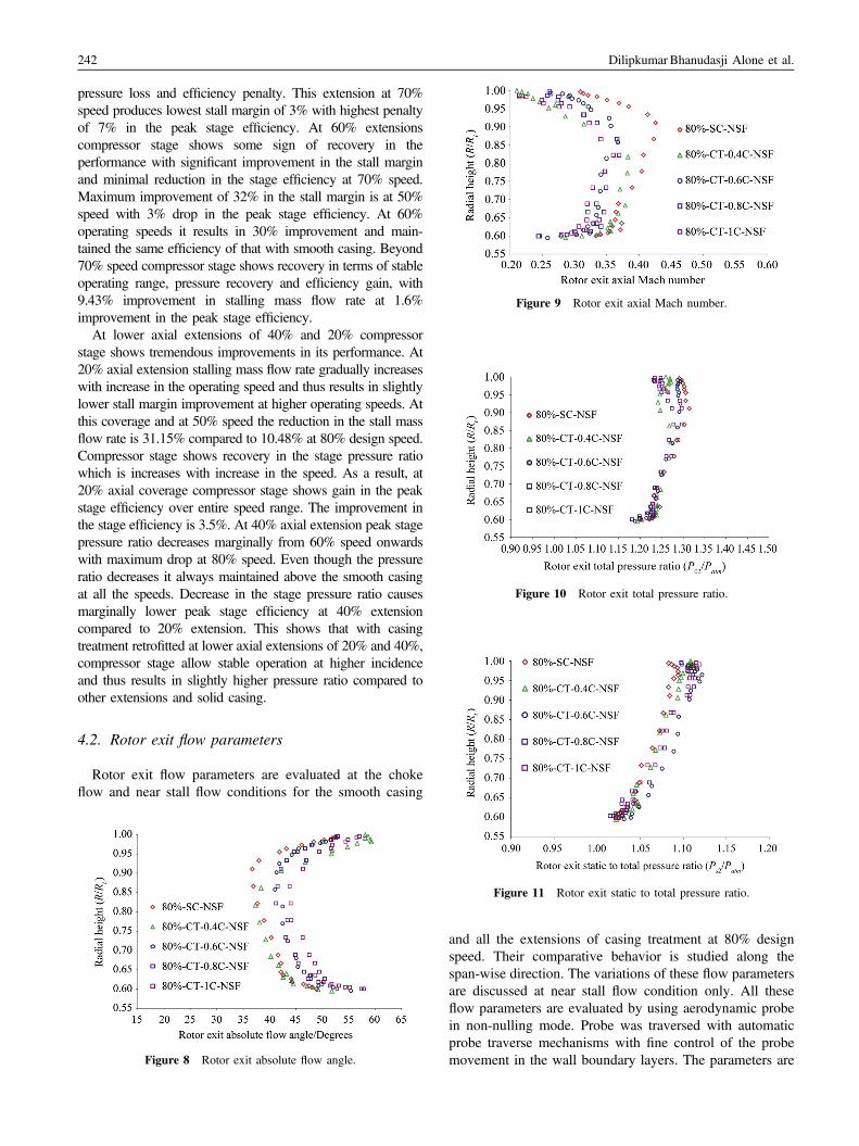
Figure 9 Rotor exit axial Mach number.
Figure 10 Rotor exit total pressure ratio.
Dilipkumar Bhanudasji Alone et al.242
pressure loss and efficiency penalty. This extension at 70%speed produces lowest stall margin of 3% with highest penaltyof 7% in the peak stage efficiency. At 60% extensionscompressor stage shows some sign of recovery in theperformance with significant improvement in the stall marginand minimal reduction in the stage efficiency at 70% speed.Maximum improvement of 32% in the stall margin is at 50%speed with 3% drop in the peak stage efficiency. At 60%operating speeds it results in 30% improvement and main-tained the same efficiency of that with smooth casing. Beyond70% speed compressor stage shows recovery in terms of stableoperating range, pressure recovery and efficiency gain, with9.43% improvement in stalling mass flow rate at 1.6%improvement in the peak stage efficiency.At lower axial extensions of 40% and 20% compressor
stage shows tremendous improvements in its performance. At20% axial extension stalling mass flow rate gradually increaseswith increase in the operating speed and thus results in slightlylower stall margin improvement at higher operating speeds. Atthis coverage and at 50% speed the reduction in the stall massflow rate is 31.15% compared to 10.48% at 80% design speed.Compressor stage shows recovery in the stage pressure ratiowhich is increases with increase in the speed. As a result, at20% axial coverage compressor stage shows gain in the peakstage efficiency over entire speed range. The improvement inthe stage efficiency is 3.5%. At 40% axial extension peak stagepressure ratio decreases marginally from 60% speed onwardswith maximum drop at 80% speed. Even though the pressureratio decreases it always maintained above the smooth casingat all the speeds. Decrease in the stage pressure ratio causesmarginally lower peak stage efficiency at 40% extensioncompared to 20% extension. This shows that with casingtreatment retrofitted at lower axial extensions of 20% and 40%,compressor stage allow stable operation at higher incidenceand thus results in slightly higher pressure ratio compared toother extensions and solid casing.
4.2. Rotor exit flow parameters
Rotor exit flow parameters are evaluated at the chokeflow and near stall flow conditions for the smooth casing
Figure 8 Rotor exit absolute flow angle.
Figure 11 Rotor exit static to total pressure ratio.
and all the extensions of casing treatment at 80% designspeed. Their comparative behavior is studied along thespan-wise direction. The variations of these flow parametersare discussed at near stall flow condition only. All theseflow parameters are evaluated by using aerodynamic probein non-nulling mode. Probe was traversed with automaticprobe traverse mechanisms with fine control of the probemovement in the wall boundary layers. The parameters are

Stability management of high speed axial flow compressor stage through axial extensions of bend skewed casing treatment 243
discussed here are rotor exit absolute flow angle, axialMach number, total and static pressure ratio.
4.2.1. Rotor exit absolute flow angle and axial Mach numberFigure 8 shows the variations of rotor exit absolute flow
angle. A variation is plotted along the blade height as non-dimensional radial height (R/Rt). Absolute flow angle gives thedegrees of the variation of absolute swirl imparted by the rotorat the rotor exit. Profile shows gradual decrements in the swirlas a result of lower blade curvature along the blade span till90% of the blade span. It is also functions of axial velocitywhich is increases till 90% blade span as shown in Figure 9. Inthe tip region swirl again increases due to the boundary layereffects and decrease in the axial velocity caused by flowretardations close to the wall.
The variation in the flow angle from rotor hub to tip issignificant at near stall conditions because of closure of exitthrottle valve. Closure of exit valve reduces the mass flow ratethrough the compressor stage which reduces the axial Machnumber, which further cause increase in the inlet incidence.The increase in the incidence further increases the flowdeviations at the rotor exit and thus increase the flow angle.
Figure 12 Comparative variations of rotor inlet axial and tangential velocaxial and tangential velocities, (b) variations of rotor inlet axial and tangetangential velocities, and (d) exploded view of FFT showing the dominati
For the smooth casing flow angle increases up to 521 in the tipwhereas it was 481 in the hub section. Flow angle increaseswith the casing treatment extensions as results of reductions inthe axial velocity and can be seen from Figure 9.
At 40% axial extension the flow angle is more because oflower stalling mass flow rate as confirmed from Figure 5.This retardation is very rapid in the tip zone. Flow anglemeasured in the tip region with this coverage is close to 601.Another interesting observations is that even though the100% axial coverage results in lower stall margin improve-ments, probe measurements shows the flow retardationscaused by the slots throughout the blade span, due to moreexposure of the casing slots and plenum to the rotor. Theperformance of 60% and 80% extensions falls in between40% and 100% axial coverage.
4.2.2. Rotor exit total pressure and static to total ratioFigures 10 and 11 show the comparative variations of rotor
exit total pressure and static to total pressure ratio respectivelyat near stall flow condition. Total pressure profile is skewed inthe tip region and skewness is increased with casing treatmentcompared to smooth casing. Total and static, both the pressure
ity for the smooth casing at stall condition. (a) Variations of rotor inletntial velocities for six rotor revolutions, (c) FFT rotor inlet axial andng stalls frequencies.

Dilipkumar Bhanudasji Alone et al.244
increases toward the tip till 90% span, beyond which it startdrooping because of casing wall effects. Increase in the totaland static pressure in the span wise directions is due to morework imparted by the dynamic action of the compressor rotorbecause of higher local peripheral speed. Smooth casing showsmarginally higher pressure ratio throughout the blade height aswith smooth casing compressor stalls at higher mass flow ratecompared to all the extensions of casing treatments. Howeverfor all the casing treatment extensions static pressure is higherthan the smooth casing as with casing treatments compressorstage stalls at a lower mass flow rate and thus improves thediffusion and can be observe from Figure 11. Diffusion ishighest in the tip region with casing treatments.
Figure 13 Comparative variations of rotor inlet axial velocity for the smoVariations of rotor inlet axial velocity for the smooth casing and four axial eaxial velocity for the smooth casing and four axial extensions of bend skewaxial velocity for the smooth casing and four axial extensions of bend skewestall frequencies.
4.3. Rotor inlet axial and tangential velocities forsmooth casing and casing treatment at stall condition
During the stall conditions the inlet velocity fluctuates inthe axial and tangential directions. The fluctuations arepredominant in the rotor inlet and at the tip section.Behavior of the axial and tangential velocities is studiedusing single component hot wire probe for the smoothcasing and casing treatments. In stall, behavior of the axialvelocity is studied for four axial extensions of the casingtreatment and tangential velocity is studied for the two axialextensions.
oth casing and casing treatment extensions at stall flow conditions. (a)xtensions of bend skewed casing treatment, (b) variations of rotor inleted casing treatment for the six rotor revolutions, (c) FFT of rotor inletd casing treatment, and (d) exploded view of FFT showing dominating

Stability management of high speed axial flow compressor stage through axial extensions of bend skewed casing treatment 245
4.3.1. Smooth casingWhen the compressor stage is fitted with smooth casing it
stalls at relatively higher mass flow rate compare to casingtreatments. The compressor stage shows abrupt nature ofthe stall as after the peak pressure ratio even smaller closureof the exit throttle valve, compressor enters into the instablemode. The behavior of the inlet axial velocity is studied andcompared with the other axial extensions. The unsteadydata plotted here for the 60% design speed due to thelimitations of hot wire sensor. Figure 12 shows the behaviorof instantaneous inlet axial and tangential velocities mea-sured at the rotor inlet in the tip region, with the help ofsingle component hot wire probe. Unsteady data is acquiredwith sampling frequency of 50 kHz. From Figure 12(a) and(b) is very clear that the oscillations in the axial andtangential velocities are very rapid and high for the smoothcasing and also can be confirm from the FFT plots shown inFigure 12(c) and (d). The inlet axial velocity varies from188 m/s to 10 m/s very rapidly and thus indicate high
Figure 14 Comparative variations of rotor inlet tangential velocity for the(a) Variations of rotor inlet tangential velocity for the smooth casing and forotor inlet tangential velocity for the smooth casing and two axial extensionof rotor inlet tangential velocity for the smooth casing and two axial extenshowing dominating stall frequencies.
intensity of stall. The tangential velocity also present andshow the signifying dominances. Its magnitude almostreaches the tangential speed of the rotor and few occasionsit matches with the magnitude of axial velocity.
The presence of tangential components gives the activenature to the stall cell. Compressor possesses abrupt natureof stalling characteristics with smooth casing. Growth oftangential velocity increases the rotor inlet blockage sig-nificantly and causing the rotor incidence to increasestalling value. As plotted in the FFT results shown inFigure 12(c) and (d), it is clear that stall cells travels at70 Hz which is 53% of the normal stalling frequency at thisspeed. From Figure 12(b) is clearly seen that for the sixrotor revolutions that correspond to 0.045 s, there are threedistinct axial and tangential velocity peaks. One stall cellstravels corresponds to two rotor revolutions, indicate thatstall cell travels at nearly half the rotor speed.
At stall conditions the amplitude of oscillations of theaxial velocity is significantly higher compared to that of
smooth casing and casing treatment extensions at stall flow conditions.ur axial extensions of bend skewed casing treatment, (b) variations ofs of bend skewed casing treatment for the six rotor revolutions, (c) FFTsions of bend skewed casing treatment, and (d) exploded view of FFT

Figure 15 Variations of turbulent Intensity.
Dilipkumar Bhanudasji Alone et al.246
tangential velocity. For axial velocity the amplitude ofoscillations is almost touching 30 m/s whereas for intangential directions it is merely 7.5 m/s. From this wecan conclude that axial components are still dominating inthe stall regions. This could be because of location of themeasurement plane which is 1 chord away from the rotorleading edge. Trends shows that very close to rotor leadingedge tangential component may be dominating over theaxial components. At this operating condition with smoothcasing Turbulence Intensity calculated is 41.75% which iscomparatively higher than all the casing treatment exten-sions and can be confirm from Figure 15.
Figure 16 Flow behaviors in the plenum chamber at choke flow andstall conditions at 60% speed. (a) Plenum chamber velocity behavior atchoke flow and stall conditions, (b) exploded view showing variationsfor six rotor revolution, and (c) FFT of velocity signals.
4.3.2. Axial extensions of bend skewed casing treatmentBehavior of the inlet axial velocity and tangential
velocity at stall conditions is studied for different axialextensions of casing treatments. The variation of thetangential velocity is compared with the smooth casing.The location of the hot wire probe was kept same for all themeasurements. Figure 13 shows the comparative behaviorof inlet axial velocity for smooth casing and 20%, 40%,60%, 100% axial extensions of bend skewed casingtreatment. From Figure 13(a) and (b), it is clear that withall the extensions of casing treatments compressors stalls atlower mass flow rate and thus enhanced the stall margin ofthe compressor stage at this speed. At stall conditions thelowest mean axial velocity of 62 m/s measured is with 20%axial coverage compared to 92 m/s with smooth casing.Amongst all the casing treatment extensions, highest axialvelocity at stall is 68 m/s with 100% extension, whereasother two axial extensions of 60% and 40% it falls inbetween 20% and 100% axial extensions. With increase inthe axial extensions from 20% to 100% stall cells sloweddown and travels at slightly lower speed and can be seenfrom the FFT analysis shown in Figure 13(c) and (d).At 100% axial extensions stall cell travels at 60 Hz which
corresponds to 45% of the rotor speed, at 60% extension ittravels at 63 Hz which corresponds to 48% of the rotor
speed and with 20% coverage it travels at 73 Hz, whichcorresponds to 55% of the rotor speed. The amplitude ofoscillations reduces with the casing treatment compared tothat of with smooth casing. Oscillations are highest with60% axial extensions as for this axial extension the bendpart of the casing treatments come over the rotor leadingedge. For this extension this bend part is located above thesensitive portion of the rotor chord and thus causing suddenchange in the upcoming streamlines. This increases theoscillations in the flow and thus also increases the turbulent

Stability management of high speed axial flow compressor stage through axial extensions of bend skewed casing treatment 247
intensity compared to other axial extensions and can beseen from Figure 15. Turbulent intensity based on the axialvelocity is calculated using the mean and root mean square(rms) values of axial velocity and using Eq. (5)
Turbulent Intensity ð%Þ ¼ Vrms
Vmeanð5Þ
Tangential velocity measurements are shown inFigure 14. Comparative behavior of tangential velocity isstudied only for the axial extensions of 20% and 40%. Theflow behavior is compared with the smooth casing. FromFigure 14(a) and (b) it is clear that with casing treatment isin place, the fluctuations in the tangential velocity reducedsignificantly. Casing treatment at these axial extensions isable to remove the blockage created by the tangentialvelocity at stall. At 40% axial extension also the appearanceof tangential components of the velocity is very smallcompared to smooth casing. Further placing the treatment at20% axial extension the oscillations in the tangentialdisappeared and can be confirmed from the FFT resultsshown in Figure 14(c) and (d). At 20% axial extensions andat stall condition aerodynamic blockage created due to theboundary layer growth/separations ahead of the rotorleading edges are effectively eliminated. This phenomenonallows compressor stage to operate at higher incidencewithout going into abrupt stall as with the smooth casing.These mechanisms results in progressive nature of stallwhich further improve the pressure recovery of the com-pressor stage and can be seen from the compressorperformance map shown in Figure 4.
4.3.3. Velocity measurements in the plenum chamberVariation of the flow velocity emerging from the casing
slots in the plenum chamber is measured for the 100% axialextensions. Probe was placed at half the plenum depth fromthe top wall. The flow in the plenum chamber is verycomplicated as the flow was neither coming in axial nor inthe tangential direction. Single component probe may notgive the actual picture of the complex and swirling flowentering the plenum chamber through the casing slots.Probe was rotate to get the actual flow direction and finallyaligned to the direction where the velocity of the flow washighest. To confirm the direction of swirling flow enteringthe plenum flow visualizations was done using tufts. Flowwas entering the plenum chamber from the rear section ofthe casing treatment slots at an angle of 451 and goingtowards the front section of the slots. The measurementswere carried out at 100% axial extensions at choke flow andstall flow condition. Figure 16 shows the variation of flowvelocity in the plenum chamber. At choke flow conditionthe mean velocity measured in the plenum chamber was40 m/s, which was lower than the main stream velocity atthis condition.
The pressurized fluid from the rear section of the bladewas entering the chamber through the slots and leavingthrough other slots. The severity of the flow entering theplenum chamber was more in the stall condition due to
additional back pressure. The plenum chamber is acting as abridge for channelizing the flow from high pressure to lowpressure side. At stall condition and at this coverage plenumchamber was getting filled with the fluid and thus the flowvelocity was almost reaches to 1 to 2 m/s and can be seenfrom Figure 16(a) and exploded view shown in Figure 16(b). From these figures it is quite clear that in addition topressure difference there was periodic injection of the fluidinto the plenum chamber as rotor blade passes the casingtreatment slots. Periodic injections of the fluids can beobserved from the velocity peak. Each 0.016 s represent thetime required for one stall event with 100% axial extensionswhich is slightly higher than the normal stalling frequencyof half of the rotor speed. With this axial extensions stallcells travels at 45% of the rotor speed and can be seen fromFFT analysis shown in Figure 16(c).
Turbulent intensity was calculated at this condition atchoke flow and stall conditions. The intensity of turbulencewas 11% at choke condition whereas it reaches to 66% withstall conditions. From this we can conclude that the flowentering the plenum is highly swirly and thus increase theturbulence level. This turbulence further causes mixinglosses which results in the total pressure loss and degrada-tions in the efficiency of the stage with this axial extension.
5. Conclusions
From the experimental studies on the axial extensions ofbend skewed casing treatments following conclusions aredrawn.
1. All the extensions of casing treatment do not producethe fruitful results. Axial extensions of 100% at 80%speed compressor stage stalls at higher mass flow rateand results in negative stall margin.
2. At 80% axial extensions the at all the operating speedsexcepts 70% compressor stall with lower mass flow rateand results in significant gain in the stall margin, butagain in terms of pressure loss and efficiency penalty.
3. At 60% extensions compressor stage performanceshows significant improvement with maximum improve-ment of 32% in the stall margin at 50% speed with 3%drop in the peak stage efficiency.
4. Beyond 70% speed compressor stage shows recovery interms of stable operating range, pressure recovery andefficiency gain.
5. At lower axial extensions of 40% and 20% compressorstage performance improves drastically. At 20% axialextensions stall margin improvement at lower operatingspeed is higher than at higher operating speed. Com-pressor stage shows recovery in the stage pressure ratiowhich is increases with increase in the speed.
6. Rotor inlet hot wire measurements shows that withsmooth casing inlet axial velocity varies very rapidlyand thus indicates the very strong nature of stall. Thepresence of the tangential velocity in the stall gives the

Dilipkumar Bhanudasji Alone et al.248
active nature to the stall cell. Growth of tangentialvelocity increases the rotor inlet blockage significantlycausing the rotor incidence to increase stalling value.
7. For the smooth casing stall cells travels at 53% of therotor speed. At stall conditions the amplitude of oscilla-tions of the axial velocity is significantly highercompared to that of tangential velocity.
8. At stall conditions with 20% axial coverage compressorstall at lowest mean axial velocity of 62 m/s comparedto 92 m/s with smooth casing. Amongst all the casingtreatment extensions, highest axial velocity at stallcondition is 68 m/s with 100% extension.
9. With increase in the axial extensions from 20% to 100%stall cells slowed down by traveling at slightly lowerspeed. At 100% axial extensions stall cell travels at 45%of the rotor speed, at 60% extension it travels at 48% ofthe rotor speed and with 20% coverage it travels at 55%of the rotor speed.
10. When the bend skewed casing treatment is in placed thefluctuations in the tangential velocity reduces signifi-cantly. At 20% and 40% axial extensions casingtreatment remove the blockage created by the tangentialvelocity at stall condition. These further results inprogressive nature of stall with this type of casingtreatment.
11. It will be interesting to carry out in depth unsteadycomputational analysis to understand the flow physicsassociated with this casing treatment coupled to axialflow compressor stage in near future.
12. The main limitations of this experimental study were acompressor stage performance evaluation restricted upto 80% design. The performance evaluation could notcarry out at design speed due to rotor dynamics issues. Itwill be interesting to see behavior of compressor stagein the presence of bend skewed casing treatmentconditions at design condition in near future.
13. Another limitation is the unsteady measurements usinghot wire probes. The measurements were restricted till60% design speed to avoid potential damage to the hotwire probe. Specifically design hot wire probe orunsteady probe can be used for higher speed in nearfuture.
14. Also, the specifically designed multipoint probe can beused to resolve the unsteady flow field in the bendskewed casing treatment slots in near future.
Acknowledgments
Authors take this opportunity to thank Director, CSIR-NAL, for funding the research program through eleventhsfive year plan and allow publishing the results. Indefatig-able hard work of Mr. Joseph Arul Raj and Mr. G.S. Ravi,Team members of AFCR are genuinely accredited. Wewould also like to express thanks to Head, PropulsionDivision and Electrical Section, NWTC, Belur for theirsupport and encouragement. Also special thanks are due to
Mr. Veera Sheshakumar and Mr. Vijay Tijare for helping inrotor dynamics aspects of the test rig.
References
[1] E.M. Greitzer, J.P. Nikkanen, H.D. Joslyn, Fundamentalcriterion for the application of rotor casing treatment, Trans.ASME J. Fluid Eng. 101 (1979) 237–243.
[2] L. Venzel, J.E. Moss Jr, Effect of casing treatment onperformance of multistage compressor, NASA TMX-3175,Jan., 1975.
[3] D. Urasek, Effect of casing treatment on performance of atwo stage high pressure ratio fan, NASA-TP-1409, Feb.,1779.
[4] D. Royce W. Osborn. Effect of tip clearance on overallperformance of transonic fan stage with and without casingtreatment, NASA TMX-3479, 1977.
[5] S.A. Guruprasad, Experimental investigations on the influ-ence of axial extension and location of outer casing treatmenton the performance of an axial flow compressor, in:Proceedings of the 4th International Symposium AIF, Dres-den, Germany, 1999.
[6] H. Takata, Y. Tsukuda, Stall margin improvement by casingtreatment, its mechanism and effectiveness, ASME J. Eng.Power 1 (1977) 237–243.
[7] H. Fujita, H. Takata, A study on configurations of casingtreatment for axial flow compressors, Bull. JSME 27 (230)(1984) 1675–1681.
[8] G.D.J. Smith, N.A. Cumptsy, Flow phenomenon in com-pressor casing treatment, Trans. ASME, J. Eng. Gas.Turbines Power 106 (3) (1984).
[9] P.C. Adams, G.D.J. Smith, The effect of axial slot casingtreatment geometry on the stall margin improvement andefficiency of a low speed axial flow compressor, ISABE 87-7036, 1987.
[10] R. Emmrich, H. Hönen, R. Niehuis, Time resolved investiga-tions of an axial compressor with casing treatment, part-1:experiment, GT2007-27581, in: Proceedings of the ASMETurbo Expo: Power for Land, Sea and Air, Montreal Canada,2008.
[11] R. Emmrich, R. Kunte, H. Hönen, R. Niehuis, Time resolvedinvestigations of an axial compressor with casing treatment,part 2: experiment, GT2007-27582, in: Proceedings of theASME Turbo Expo: Power for Land, Sea and Air, MontrealCanada, 2008.
[12] R. Emmrich, H. Hönen, R. Niehuis, Time resolved experi-mental investigations of an axial compressor with casingtreatment, J. Turbomach. 131 (2009) 011018-1-9.
[13] J. Zhu, W. Chu, The effects of bend skewed groove casingtreatment on performance and flow field near end wall of anaxial compressor, AIAA 2005-809, in: Proceedings of the43rd AIAA Aerospace Sciences meeting and exhibit, 10–13January, Reno, Nevada, 2005.
[14] X. Lu, W. Chu, Y. Zhang, J. Zhu, Experimental andnumerical investigation of a subsonic compressor withbend-skewed slot-casing treatment, Proc. IMechE Vol. 220Part C: J. Mech. Eng. Sci. (2006).
[15] X. Lu, J. Zhu, C. Nie, W.H. Huang, The stability-limiting ina subsonic axial flow compressor and its passive control withcasing treatment, GT2008-50006, in: Proceedings of the

Stability management of high speed axial flow compressor stage through axial extensions of bend skewed casing treatment 249
ASME Turbo Expo: Power for Land, Sea and Air, Berlin,Germany, 2008.
[16] X. Lu, W. Chu, J. Zhu, Y. Zhang, Numerical investigationsof the coupled flow through a subsonic compressor rotor andaxial skewed slot, J. Turbomach. 131 (2009) 011001-1.
[17] N. Gourdain, M. Montagnac, J.F. Boussuge, Numericalsimulation of an axial compressor with non-axisymmetriccasing treatment, in: Proceedings of the 2nd EuropeanConference for Aerospace Sciences (EUCASS).
[18] M. Voges, R. Schnell, C. Willert, R. Mönig, M.W. Müller, C.Zscherp, Investigation of blade tip interaction with casingtreatment in a transonic compressor, part 1: particle imagevelocimetry, GT2008-50210, in: Proceedings of the ASMETurbo Expo: Power for Land, Sea and Air, Berlin, Germany,2008, Journal of Turbomachinery 133 (2011) 011007-1.
[19] R. Schnell, M. Voges, R. Mönig, M.W. Müller, C. Zscherp,Investigation of blade tip interaction with casing treatment ina transonic compressor, part 2: numerical results, GT2008-50212, in: Proceedings of the ASME Turbo Expo: Power forLand, Sea and Air, Berlin, Germany, 2008, Journal ofTurbomachinery 133 (2011) 011008-1.
[20] M. Voges, C. Willert, RMönig, H.P. Schiffer, The effect of abend-slot casing treatment on the blade tip flow field of atransonic compressor rotor, GT2013-94006, in: Proceedingsof the ASME Turbo Expo, Turbine Technical Conferenceand Exposition, San Antonio, Texas, USA, 2013.
[21] D.B. Alone, S. Satish Kumar, M.T. Shobhavathy, J.R.Reddy, A.M. Pradeep, S. Ramamurthy, S.V. Iyengar, Per-formance characterization of the effect of axial positioning ofbend skewed casing treatment retrofitted to a transonic axialflow compressor, GT2014-26099, in: Proceedings of theASME Turbo Expo, June 16–20, Dusseldorf, Germany,2014.
[22] D.B. Alone, S. Satish Kumar, M.T. Shobhavathy, J.R.Reddy, A.M. Pradeep, S. Ramamurthy, S.V. Iyengar, Experi-mental investigation on the effect of porosity of bend skewedcasing treatment on a single stage transonic axial flowcompressor, GT2014-26102, in: Proceedings of the ASMETurbo Expo, June 16–20, Dusseldorf, Germany, 2014.
[23] D.B. Alone, S. Satish Kumar, M.T. Shobhavathy, J.R.Reddy, A.M. Pradeep, S. Ramamurthy, S.V. Iyengar, Onunderstanding the effect of plenum chamber of a bendskewed casing treatment on the performance of a transonicaxial flow compressor, GT2014-26103, in: Proceedings ofthe ASME Turbo Expo, June 16–20, Dusseldorf, Germany,2014.
[24] D.B. Alone, S. Satish Kumar, M.T. Shobhavathy, J.R.Reddy, A.M. Pradeep, S. Ramamurthy and S.V. Iyengar,Improvement of moderately loaded transonic axial compres-sor performance using low porosity bend skewed casingtreatment, Int. J. Rotating Mach. 2014 (2014), 14 pp. ArticleID 625876, http://dx.doi.org/10.1155/2014/625876.