
Sony Ta Dx80
14
SERVICE MANUAL INTEGRATED STEREO AMPLIFIER E Model SPECIFICATIONS TA-DX80 Ver 1.0 2001.03 9-929-592-11 Sony Corporation 2001C0500-1 Audio Entertainment Group C 2001.3 General Engineering Dept. TA-DX80 is the amplifier section in MHC-DX80, MHC-VX888. The following measured at AC 120, 220, 240 V 50/60 Hz DIN power output (rated) 75 + 75 watts (6 ohms at 1 kHz, DIN) Continuous RMS power output (reference) 100 + 100 watts (6 ohms at 1 kHz, 10% THD) Inputs MD/VIDEO (AUDIO) IN: voltage 450 mV/250 mV, (phono jacks) impedance 47 kilohms MIC: sensitivity 1 mV, (phone jack) impedance 10 kilohms Outputs PHONES: accepts headphones of (stereo mini jack) 8 ohms or more FRONT SPEAKER: accepts impedance of 6 to 16 ohms SURROUND SPEAKER: accepts impedance of 6 ohms General Power requirements Mexican models: 120 V AC, 60Hz E91 models: 220 V AC, 50/60 Hz Other models: 120 V, 220 V or 230 – 240 V AC, 50/60Hz Adjustable with voltage selector Power consumption 180 watts Dimensions (w/h/d) Approx. 150 × 360 × 343 mm Mass: Approx. 5.5 kg Design and specifications are subject to change without notice. • Abbreviation E91: 220 V AC area in E model
-
Upload
heladiomontesdeoca -
Category
Documents
-
view
237 -
download
6
Transcript of Sony Ta Dx80

SERVICE MANUAL
INTEGRATED STEREO AMPLIFIER
E Model
SPECIFICATIONS
TA-DX80Ver 1.0 2001.03
9-929-592-11 Sony Corporation2001C0500-1 Audio Entertainment Group
C 2001.3 General Engineering Dept.
TA-DX80 is the amplifier section inMHC-DX80, MHC-VX888.
The following measured at AC 120, 220, 240 V 50/60 HzDIN power output (rated) 75 + 75 watts
(6 ohms at 1 kHz, DIN)Continuous RMS power output (reference)
100 + 100 watts(6 ohms at 1 kHz, 10% THD)
InputsMD/VIDEO (AUDIO) IN: voltage 450 mV/250 mV,(phono jacks) impedance 47 kilohmsMIC: sensitivity 1 mV,(phone jack) impedance 10 kilohmsOutputsPHONES: accepts headphones of(stereo mini jack) 8 ohms or moreFRONT SPEAKER: accepts impedance of 6 to 16 ohmsSURROUND SPEAKER: accepts impedance of 6 ohms
GeneralPower requirementsMexican models: 120 V AC, 60HzE91 models: 220 V AC, 50/60 HzOther models: 120 V, 220 V or 230 – 240 V AC, 50/60Hz
Adjustable with voltage selector
Power consumption 180 watts
Dimensions (w/h/d) Approx. 150 × 360 × 343 mmMass: Approx. 5.5 kg
Design and specifications are subject to change without notice.
• AbbreviationE91: 220 V AC area in E model
2
TA-DX80
TABLE OF CONTENTS
1. SERVICING NOTE .................................................. 2
2. GENERAL ................................................................... 3
3. DISASSEMBLY3-1. Disassembly Flow ........................................................... 43-2. Case ................................................................................. 43-3. Front Panel Section ......................................................... 53-4. MAIN Board ................................................................... 5
4. DIAGRAMS4-1. Note for Printed Wiring Boards and
Schematic Diagrams ....................................................... 54-2. Printed Wiring Board – MAIN Board – ........................ 64-3. Schematic Diagram – MAIN Board – ........................... 74-4. Printed Wiring Boards
– INLET/PANEL/TRANS Boards – .............................. 84-5. Schematic Diagram
– INLET/PANEL/TRANS Boards – .............................. 9
4. EXPLODED VIEW ................................................... 10
5. ELECTRICAL PARTS LIST ............................... 10
SAFETY-RELATED COMPONENT WARNING!!
COMPONENTS IDENTIFIED BY MARK 0 OR DOTTEDLINE WITH MARK 0 ON THE SCHEMATIC DIAGRAMSAND IN THE PARTS LIST ARE CRITICAL TO SAFEOPERATION. REPLACE THESE COMPONENTS WITHSONY PARTS WHOSE PART NUMBERS APPEAR ASSHOWN IN THIS MANUAL OR IN SUPPLEMENTS PUB-LISHED BY SONY.
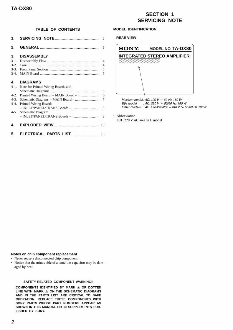
MODEL IDENTIFICATION
– REAR VIEW –
Notes on chip component replacement• Never reuse a disconnected chip component.• Notice that the minus side of a tantalum capacitor may be dam-
aged by heat.
MODEL NO. TA-DX80
INTEGRATED STEREO AMPLIFIER
Mexican model : AC: 120 V - 60 Hz 180 WE91 model : AC: 220 V - 50/60 Hz 180 WOther models : AC: 120/220/230 – 240 V - 50/60 Hz 180W
• AbbreviationE91: 220 V AC area in E model
SECTION 1SERVICING NOTE

3
TA-DX80SECTION 2GENERAL
This section is extracted frominstruction manual.
• LOCATION OF CONTROLS
– Front view –
1 Indicator
2 LINK/SURROUND/SUB WOOFER indicator
3 SURROUND SPEAKER MODE switch
4 SURROUND SPEAKER LEVEL control
1 SYSTEM CONTROL connector
2 SPEAKER terminal
3 VOLTAGE SELECTOR switch
(EXCEPT Mexican and E91 models)
4 - AC IN terminal
• AbbreviationE91: 220 V AC area in E model
– Rear view –
1
2
3
4

4
TA-DX80
• This set can be disassembled in the order shown below.
3-1. DISASSEMBLY FLOW
SECTION 3DISASSEMBLY
Note: Follow the disassembly procedure in the numerical order given.
3-2. CASE
3-3. FRONT PANEL SECTION(Page 5)
3-2. CASE(Page 4)
3-4. MAIN BOARD(Page 5)
1 screw (case3 TP2)(8 mm)
1 screw (case3 TP2)(10 mm)
1 screw (case3 TP2)(10 mm)
1 screw (case3 TP2)(8 mm)
2 three screws(BVTP3 × 8)
2 four screws(BVTP3 × 8)
3 case

TA-DX80
55
3-3. FRONT PANEL SECTION
3 screw(BVTP3 × 10)
5 two screws(BVTP3 × 10)
6 two screws(BVTP3 × 16)
3 two screws(BVTP3 × 8)
4
8 MAIN board
1 wire (flat type) (15 core)(CN111)
7 heat sink assy
2 connector(CN501)
4 front panel section
1 wire (flat type) (15 core)(CN111)
3 claw
2 three screws(BVTP3 × 8)
3-4. MAIN BOARD
SECTION 4DIAGRAMS
4-1. NOTE FOR PRINTED WIRING BOARDS AND SCHEMATIC DIAGRAMS
Note on Printed Wiring Board:• X : parts extracted from the component side.• Y : parts extracted from the conductor side.• : Pattern from the side which enables seeing.• Indication of transistor.
B
These are omitted.
C E
Q
B
These are omitted.
C E
Q
Note on Schematic Diagram:• All capacitors are in µF unless otherwise noted. pF: µµF
50 WV or less are not indicated except for electrolyticsand tantalums.
• All resistors are in Ω and 1/4 W or less unless otherwise
specified.• 2 : nonflammable resistor.• 5 : fusible resistor.• C : panel designation.
• A : B+ Line.• B : B– Line.• Voltages are dc with respect to ground under no-signal
conditions.• Voltages are taken with a VOM (Input impedance 10 MΩ).
Voltage variations may be noted due to normal produc-tion tolerances.no mark : POWER ON
• Signal path.F : AUDIO
• AbbreviationBR : Brazilian modelE91 : 220 V AC area in E modelMX : Mexican model
Note: The components identified by mark 0 or dotted linewith mark 0 are critical for safety.Replace only with part number specified.
• AbbreviationE91 : 220 V AC area in E modelMX : Mexican model

TA-DX80
66
JW301
C104
C154
IC101
R311
R312
D301
D302
C103C153
R104
C152
R154
C102
IC111
C101
C151
C113
R115
C111
C112Q111
R111R112
R113
R116
R152
Q124
R102
Q125
C114
IC141
C141
C191
R141
R101
R191
R192
R142
R155
TM301
C123
C173
C303
JW101
JW11
0
JW11
1
JW11
2
JW11
3
JW114
JW115
JW118
JW11
9
JW12
0
JW12
1
JW210
JW10
8
R151
JW10
5
JW104
R105
R136
Q127
R135
JW10
01
JW12
2
C262
R554
Q122
Q123
R126
R206
C551
C202
C502
R268
C203
R127
R201
C201
R202
R203
C204
C206
C207R211
R213
D251
R205
R256
R255
R505
R251
Q201
Q251
Q263
R266
R261
R267
R208
R210
R214
R212C257
C251
R252
C253
C256
C254
C552
C252
R207
R506
C255
C205
R257
D201
R253
R260
D252
R555
R556
D202
C553
C554C504
D502 D5
52
Q121
Q171
R121
R122
R123
R171
R172
R173
C231
R231
R232
R233
R234
R235
D231
R551
R501
R128
C501
R553
CN501
R258
Q126
R133
EP501
D501
IC20
1
Q551
R204
R264
R265
Q421
Q422
Q423
Q424
Q425
Q426
R435
R437
R436
R438
R433
R434
CN111
R134
R432
R430
R431
R429
JW144
JW145
JW146
JW147
JW14
8
JW14
9
JW15
0
JW151
JW152 JW153
JW156
JW157
JW158
JW159
JW160
JW161
JW162
JW163
JW164
JW16
5
JW167
JW168
JW169
JW171JW172
JW173
JW174
JW179
JW181
JW182
JW183
JW184
JW185 JW186
JW189
JW193
JW194
JW195
JW196
JW19
7 JW198
JW199
JW191
JW192
R254
C261
JW154
Q428
R443
JW15
5
R440
R441
Q427
R502
R442
R552
LP2
R504
Q321 Q323Q322
Q324
Q325
Q326 Q327
Q328
R331
R332
R325
R326
R327
R328
R330
R323
R324
R321
R322
R333
R334
D321
C322
C321
C323C324
C121
R125
IC121
Q262
Q261
R262
R263
C503
R335
C163
C161
C162 Q161
C171
R161R162
R163
R166
R165
R329
R503
R124
R130 Q501
C126
C176
JW125
JW12
6
JW128
JW129
JW130
JW131
JW13
2
JW133
JW134
JW135
JW136
JW13
7JW13
8
JW13
9
JW140
JW14
1
JW14
2
JW14
3
JW170
JW175
JW17
6
JW177
JW17
8
JW180
JW187
R185 R186
Q177
JW16
6
R129 JW127
JW12
4JW12
3
JW35
1
JW18
8
C122
C131
C132
R220
MAIN BOARD
13
12
1
2
CN101SYSTEM
CONTROL
TOHCD-DX80
ORHCD-VX888
8 1
5 4
+
–
–
+R
L
SPEAKERIMPEDANCE USE
6Ω – 16Ω
TM301
E
E
8 1
5 4
RY302-2
-1
-2
-1
RY301
8
5
1
4
E
E
E
E
E
EE E
E E E
E
E
9 8
16 1
E
C
B
B
C
E
EE
E
E
E
E
E E
E
E
E
A PANEL BOARDCN401
3 1
BTRANSBOARDNO701
E
E
E
E
E
E
E
(CHASSIS)
1-680-836-
11
(11)
B
C
D
E
F
G
H
I
J
A
1 2 3 4 5 6 7 8 9 10
4-2. PRINTED WIRING BOARD – MAIN Board –
• SemiconductorLocation
Ref. No. Location
D201 I-7D202 J-2D231 E-9D251 G-7D252 G-7D301 E-4D302 D-4D321 D-5D501 C-8D552 B-7
IC101 A-3IC111 C-4IC121 A-5IC141 C-2IC201 H-9
Q111 C-3Q121 J-9Q122 B-8Q123 B-8Q124 B-4Q125 B-4Q126 B-9Q127 C-3Q161 C-5Q171 G-9Q177 C-5Q201 J-8Q251 G-8Q261 F-6Q262 F-6Q263 H-8Q321 E-5Q322 E-5Q323 E-5Q324 D-5Q325 D-5Q326 D-4Q327 D-5Q328 D-4Q421 A-10Q422 B-10Q423 B-10Q424 C-10Q425 D-10Q426 C-10Q427 B-10Q428 B-10Q501 B-6Q551 B-7
(Page 8)
(Page 8)

TA-DX80
77
4-3. SCHEMATIC DIAGRAM – MAIN Board –
The components identified by mark 0 or dottedline with mark 0 are critical for safety.Replace only with part number specified.
(Page 9)
(Page 9)

TA-DX80
88
C451
R452
R453 C401
R451
C405C455
R402
R403
JW406
JW407
R425
R454 C453
Q404
D404
Q401
Q402Q403
R426
R427
R428R421R424
R404C403
CN401
S101
JW401
JW408
JW402
C404
C454
R439 C406
R423
R422
Q461
R455 C452 Q411
R401
R405C402
D412D462
D411
D461
JW404JW405
IC401
D406
D405 D402
D403
C591
F501F502F503
JW513 JW512JW511
NO701
JW504
JW505
CN801
PANEL BOARD
D401(STANDBY)
E E E
E
D404LINK
D403, 406SURROUND
D402, 405SUB WOOFER
AMAIN
BOARDCN111
S101SURROUND SPEAKER
MODE
3 1
S
D
G4
1
5
8
S
G
D
RV401
-1
-2
SURROUND SPEAKERLEVEL
1-680-837-
11
(11)
S501VOLTAGE SELECTOR
230-240V t 220V t 120V
(EXCEPT MX, E91)
2 1
NO801
(E91)
(MX)
(EXCEPT MX)
(EXCEPT E91)(EXCEPT MX)(EXCEPT MX, E91)
1
3
BMAIN BOARD
CN501
*
T501POWER TRANSFORMER
* NOT REPLACEABLE:BUILT IN TRANSFORMER
1-680-838-
11
(11)
TRANS BOARD
2 1
2 1 CN601~ AC IN
1-68
1-95
6-
11
(11)
INLET BOARD
B
C
D
E
F
A
1 2 3 4 5 6 7
4-4. PRINTED WIRING BOARDS – INLET/PANEL/TRANS Boards –
• SemiconductorLocation
Ref. No. Location
D401 A-1D402 B-2D403 B-2D404 B-1D405 B-1D406 B-1D411 D-2D412 E-2D461 D-1D462 E-1
IC401 E-2
Q401 B-2Q402 B-2Q403 B-1Q404 B-1Q411 E-2Q461 E-1
(Page 6)
(Page 6)

TA-DX80
99
4-5. SCHEMATIC DIAGRAM – INLET/PANEL/TRANS Boards –
The components identified by mark 0 or dottedline with mark 0 are critical for safety.Replace only with part number specified.
(Page 7)
(Page 7)

1010
TA-DX80SECTION 5
EXPLODED VIEW
The components identified bymark 0 or dotted line with mark0 are critical for safety.Replace only with part numberspecified.
• Items marked “*” are not stocked since theyare seldom required for routine service. Somedelay should be anticipated when orderingthese items.
• The mechanical parts with no reference num-ber in the exploded views are not supplied.
• AbbreviationAR : Argentina modelBR : Brazilian modelE2 : 120 V AC area in E modelE3 : Middle and Near East modelE91 : 220 V AC area in E model
NOTE:• -XX and -X mean standardized parts, so they
may have some difference from the originalone.
• Color Indication of Appearance PartsExample:KNOB, BALANCE (WHITE) . . . (RED)
↑ ↑Parts Color Cabinet's Color
• Hardware (# mark) list is given in the last ofthe electrical parts list.
Ref. No. Part No. Description Remark Ref. No. Part No. Description Remark
EA : Saudi Arabia modelIA : Indonesian modelMY : Malaysia modelMX : Mexican modelSP : Singapore model
4
3
2
5
6
9
1
7
8
10
13
#1
#2
#1
#2
#2
#2
#4
T501
#4
not supplied
not supplied
not supplied
#2
#2#3
10
1
11
9
1213
not supplied
1 4-225-252-01 CUSHION (FOOT)2 4-232-744-01 KNOB (LEVEL)3 4-232-743-01 KNOB (MODE)4 A-4412-974-A FRONT PANEL ASSY (BR)4 X-4953-604-1 FRONT PANEL ASSY (EXCEPT BR)
5 1-680-837-11 PANEL BOARD6 4-951-620-01 SCREW (2.6X8), +BVTP7 A-2007-958-A MAIN BOARD, COMPLETE (MX, E2, AR)7 A-4476-124-A MAIN BOARD, COMPLETE (EA, MY, SP, E3)7 A-4726-057-A MAIN BOARD, COMPLETE (BR)
7 A-4725-795-A MAIN BOARD, COMPLETE (E91)
7 A-4476-714-A MAIN BOARD, COMPLETE (IA)8 1-773-012-11 WIRE (FLAT TYPE) (15 CORE)9 3-363-099-41 SCREW (CASE 3 TP2) (10mm)10 3-363-099-01 SCREW (CASE 3 TP2) (8mm)11 4-227-526-31 CASE (EXCEPT BR, MX)
11 4-227-526-41 CASE (MX)11 4-227-526-51 CASE (BR)12 1-680-838-11 TRANS BOARD13 1-681-956-11 INLET BOARD
0T501 1-435-316-11 TRANSFORMER, POWER (EXCEPT BR)
0T501 1-435-663-11 TRANSFORMER, POWER (BR)
SECTION 6ELECTRICAL PARTS LIST
Ref. No. Part No. Description Remark Ref. No. Part No. Description Remark
INLET MAIN
1-681-956-11 INLET BOARD***********
< CONNECTOR >
0CN601 1-526-931-11 INLET, AC (- AC IN)* CN801 1-568-226-11 PIN, CONNECTOR 2P**************************************************************
A-2007-958-A MAIN BOARD, COMPLETE (MX, E2, AR)A-4476-124-A MAIN BOARD, COMPLETE (EA, MY, SP, E3)A-4476-714-A MAIN BOARD, COMPLETE (IA)A-4725-795-A MAIN BOARD, COMPLETE (E91)A-4726-057-A MAIN BOARD, COMPLETE (BR)
*********************
7-685-646-79 SCREW +BVTP 3X8 TYPE2 N-S
< CAPACITOR >
C101 1-126-965-11 ELECT 22uF 20% 50VC102 1-136-161-00 FILM 0.047uF 5% 50VC103 1-126-961-11 ELECT 2.2uF 20% 50VC104 1-136-165-00 FILM 0.1uF 5% 50VC111 1-136-165-00 FILM 0.1uF 5% 50V
C112 1-136-165-00 FILM 0.1uF 5% 50VC113 1-126-961-11 ELECT 2.2uF 20% 50VC114 1-162-306-11 CERAMIC 0.01uF 30% 16VC121 1-126-961-11 ELECT 2.2uF 20% 50VC122 1-109-952-11 ELECT 0.47uF 20% 50V
C123 1-162-215-31 CERAMIC 47PF 5% 50VC126 1-126-965-11 ELECT 22uF 20% 50VC131 1-126-960-11 ELECT 1uF 20% 50VC132 1-126-960-11 ELECT 1uF 20% 50VC141 1-126-961-11 ELECT 2.2uF 20% 50V
C151 1-126-965-11 ELECT 22uF 20% 50VC152 1-136-161-00 FILM 0.047uF 5% 50VC153 1-126-961-11 ELECT 2.2uF 20% 50VC154 1-136-165-00 FILM 0.1uF 5% 50VC161 1-136-165-00 FILM 0.1uF 5% 50V
C162 1-136-165-00 FILM 0.1uF 5% 50VC163 1-126-961-11 ELECT 2.2uF 20% 50VC171 1-126-961-11 ELECT 2.2uF 20% 50VC173 1-162-215-31 CERAMIC 47PF 5% 50VC176 1-126-965-11 ELECT 22uF 20% 50V
C191 1-126-961-11 ELECT 2.2uF 20% 50VC201 1-126-961-11 ELECT 2.2uF 20% 50V
NOTE:• Due to standardization, replacements in the
parts list may be different from the parts speci-fied in the diagrams or the components usedon the set.
• -XX and -X mean standardized parts, so theymay have some difference from the originalone.
• RESISTORSAll resistors are in ohms.METAL: Metal-film resistor.METAL OXIDE: Metal oxide-film resistor.F: nonflammable
• Items marked “*” are not stocked since theyare seldom required for routine service.Some delay should be anticipated when order-ing these items.
• SEMICONDUCTORSIn each case, u: µ, for example:uA. . : µA. . uPA. . : µPA. .uPB. . : µPB. . uPC. . : µPC. .uPD. . : µPD. .
• CAPACITORSuF: µF
• COILSuH: µH
The components identified bymark 0 or dotted line with mark0 are critical for safety.Replace only with part numberspecified.
When indicating parts by referencenumber, please include the board.
C202 1-162-290-31 CERAMIC 470PF 10% 50VC203 1-162-282-31 CERAMIC 100PF 10% 50VC204 1-104-664-11 ELECT 47uF 20% 10V
C205 1-136-163-00 FILM 0.068uF 5% 50V(E91)
C205 1-136-495-11 FILM 0.068uF 5% 50V(EXCEPT E91)
C206 1-136-163-00 FILM 0.068uF 5% 50V(E91)
C206 1-136-495-11 FILM 0.068uF 5% 50V(EXCEPT E91)
C207 1-128-560-11 ELECT 22uF 20% 100V
C231 1-126-959-11 ELECT 0.47uF 20% 50VC251 1-126-961-11 ELECT 2.2uF 20% 50VC252 1-162-290-31 CERAMIC 470PF 10% 50VC253 1-162-282-31 CERAMIC 100PF 10% 50VC254 1-104-664-11 ELECT 47uF 20% 10V
C255 1-136-163-00 FILM 0.068uF 5% 50V(E91)
C255 1-136-495-11 FILM 0.068uF 5% 50V(EXCEPT E91)
C256 1-136-163-00 FILM 0.068uF 5% 50V(E91)
C256 1-136-495-11 FILM 0.068uF 5% 50V(EXCEPT E91)
C257 1-128-560-11 ELECT 22uF 20% 100V
C261 1-162-306-11 CERAMIC 0.01uF 30% 16VC262 1-162-306-11 CERAMIC 0.01uF 30% 16VC303 1-137-351-11 MYLAR 0.022uF 10% 100VC321 1-104-665-11 ELECT 100uF 20% 10VC322 1-126-961-11 ELECT 2.2uF 20% 50V
C323 1-126-924-11 ELECT 330uF 20% 10VC324 1-126-965-11 ELECT 22uF 20% 50VC501 1-130-777-00 MYLAR 0.1uF 10% 100V
(EXCEPT BR)C501 1-137-749-11 MYLAR 0.1uF 100V
(BR)C502 1-127-812-11 ELECT 3300uF 20% 63V
(BR, MX, E2, AR)
C502 1-135-516-11 ELECT 3300uF 20% 63V(EA, MY, SP, IA, E3, E91)
C503 1-128-582-11 ELECT 10uF 20% 63VC504 1-126-933-11 ELECT 100uF 20% 16VC551 1-130-777-00 MYLAR 0.1uF 10% 100V
(EXCEPT BR)
• AbbreviationAR : Argentina modelBR : Brazilian modelE2 : 120 V AC area in E modelE3 : Middle and Near East modelE91 : 220 V AC area in E model
EA : Saudi Arabia modelIA : Indonesian modelMY : Malaysia modelMX : Mexican modelSP : Singapore model

Ref. No. Part No. Description Remark Ref. No. Part No. Description Remark
11
TA-DX80
C551 1-137-749-11 MYLAR 0.1uF 100V(BR)
C552 1-127-812-11 ELECT 3300uF 20% 63V(BR, MX, E2, AR)
C552 1-135-516-11 ELECT 3300uF 20% 63V(EA, MY, SP, IA, E3, E91)
C553 1-128-582-11 ELECT 10uF 20% 63VC554 1-126-933-11 ELECT 100uF 20% 16V
< CONNECTOR >
* CN101 1-565-291-11 SOCKET, CONNECTOR 13P(SYSTEM CONTROL)
CN111 1-784-776-11 CONNECTOR, FFC 15PCN501 1-564-506-11 PLUG, CONNECTOR 3P
< DIODE >
D201 8-719-911-19 DIODE 1SS133T-72 (EXCEPT BR, IA, E91)D201 8-719-991-33 DIODE 1SS133T-77 (BR, IA, E91)D202 8-719-911-19 DIODE 1SS133T-72 (EXCEPT BR, IA, E91)D202 8-719-991-33 DIODE 1SS133T-77 (BR, IA, E91)D231 8-719-911-19 DIODE 1SS133T-72 (EXCEPT BR, IA, E91)
D231 8-719-991-33 DIODE 1SS133T-77 (BR, IA, E91)D251 8-719-911-19 DIODE 1SS133T-72 (EXCEPT BR, IA, E91)D251 8-719-991-33 DIODE 1SS133T-77 (BR, IA, E91)D252 8-719-911-19 DIODE 1SS133T-72 (EXCEPT BR, IA, E91)D252 8-719-991-33 DIODE 1SS133T-77 (BR, IA, E91)
D301 8-719-911-19 DIODE 1SS133T-72 (EXCEPT BR, IA, E91)D301 8-719-991-33 DIODE 1SS133T-77 (BR, IA, E91)D302 8-719-911-19 DIODE 1SS133T-72 (EXCEPT BR, IA, E91)D302 8-719-991-33 DIODE 1SS133T-77 (BR, IA, E91)D321 8-719-911-19 DIODE 1SS133T-72 (EXCEPT BR, IA, E91)
D321 8-719-991-33 DIODE 1SS133T-77 (BR, IA, E91)D501 8-719-302-38 DIODE RBV-602-01D502 8-719-921-63 DIODE MTZJ-T-72-7.5BD552 8-719-921-63 DIODE MTZJ-T-72-7.5B
< EARTH TERMINAL >
* EP501 1-537-738-21 TERMINAL, EARTH
< IC >
IC101 8-759-167-88 IC NJM4565DIC111 8-759-167-88 IC NJM4565DIC121 8-759-208-08 IC BU4052BCIC141 8-759-167-88 IC NJM4565DIC201 8-749-016-95 IC STK402-100S
< TRANSISTOR >
Q111 8-729-119-78 TRANSISTOR 2SC2785TP-HFEQ121 8-729-141-30 TRANSISTOR 2SC3623ATP-LKQ122 8-729-029-21 TRANSISTOR DTA114ESA-TP (BR)Q122 8-729-422-57 TRANSISTOR BN1A4M-TP (EXCEPT BR)Q123 8-729-119-78 TRANSISTOR 2SC2785TP-HFE
Q124 8-729-119-78 TRANSISTOR 2SC2785TP-HFEQ125 8-729-119-78 TRANSISTOR 2SC2785TP-HFEQ126 8-729-119-78 TRANSISTOR 2SC2785TP-HFEQ127 8-729-119-78 TRANSISTOR 2SC2785TP-HFEQ161 8-729-119-78 TRANSISTOR 2SC2785TP-HFE
Q171 8-729-141-30 TRANSISTOR 2SC3623ATP-LK
Q177 8-729-119-78 TRANSISTOR 2SC2785TP-HFEQ201 8-729-140-84 TRANSISTOR 2SC1841TP-PAFAEAQ251 8-729-140-84 TRANSISTOR 2SC1841TP-PAFAEAQ261 8-729-140-84 TRANSISTOR 2SC1841TP-PAFAEA
Q262 8-729-140-82 TRANSISTOR 2SA988TP-PAFAEAQ263 8-729-140-84 TRANSISTOR 2SC1841TP-PAFAEAQ321 8-729-119-76 TRANSISTOR 2SA1175TP-HFEQ322 8-729-119-78 TRANSISTOR 2SC2785TP-HFEQ323 8-729-119-78 TRANSISTOR 2SC2785TP-HFE
Q324 8-729-119-78 TRANSISTOR 2SC2785TP-HFEQ325 8-729-119-78 TRANSISTOR 2SC2785TP-HFEQ326 8-729-140-84 TRANSISTOR 2SC1841TP-PAFAEAQ327 8-729-140-84 TRANSISTOR 2SC1841TP-PAFAEAQ328 8-729-140-84 TRANSISTOR 2SC1841TP-PAFAEA
Q421 8-729-119-78 TRANSISTOR 2SC2785TP-HFEQ422 8-729-119-78 TRANSISTOR 2SC2785TP-HFEQ423 8-729-119-78 TRANSISTOR 2SC2785TP-HFEQ424 8-729-119-78 TRANSISTOR 2SC2785TP-HFEQ425 8-729-119-78 TRANSISTOR 2SC2785TP-HFE
Q426 8-729-119-78 TRANSISTOR 2SC2785TP-HFEQ427 8-729-119-78 TRANSISTOR 2SC2785TP-HFEQ428 8-729-119-78 TRANSISTOR 2SC2785TP-HFEQ501 8-729-018-60 TRANSISTOR 2SD2012-LC (E91)Q501 8-729-026-68 TRANSISTOR 2SD2525 (TP) (EXCEPT E91)
Q551 8-729-018-59 TRANSISTOR 2SB1375 (LB-SONY) (E91)Q551 8-729-030-19 TRANSISTOR 2SB1640 (TP) (EXCEPT E91)
< RESISTOR >
R101 1-249-429-11 CARBON 10K 5% 1/4WR102 1-249-429-11 CARBON 10K 5% 1/4WR104 1-249-441-11 CARBON 100K 5% 1/4WR105 1-249-441-11 CARBON 100K 5% 1/4WR111 1-249-433-11 CARBON 22K 5% 1/4W
R112 1-249-419-11 CARBON 1.5K 5% 1/4WR113 1-247-895-00 CARBON 470K 5% 1/4WR115 1-249-441-11 CARBON 100K 5% 1/4WR116 1-249-437-11 CARBON 47K 5% 1/4WR121 1-249-433-11 CARBON 22K 5% 1/4W
R122 1-249-417-11 CARBON 1K 5% 1/4WR123 1-249-429-11 CARBON 10K 5% 1/4WR124 1-249-429-11 CARBON 10K 5% 1/4WR125 1-249-429-11 CARBON 10K 5% 1/4WR126 1-249-425-11 CARBON 4.7K 5% 1/4W
R127 1-249-441-11 CARBON 100K 5% 1/4WR128 1-249-429-11 CARBON 10K 5% 1/4WR129 1-249-429-11 CARBON 10K 5% 1/4WR130 1-249-429-11 CARBON 10K 5% 1/4WR133 1-249-429-11 CARBON 10K 5% 1/4W
R134 1-249-441-11 CARBON 100K 5% 1/4WR135 1-247-899-11 CARBON 680K 5% 1/4WR136 1-249-429-11 CARBON 10K 5% 1/4WR141 1-249-429-11 CARBON 10K 5% 1/4WR142 1-249-429-11 CARBON 10K 5% 1/4W
R151 1-249-429-11 CARBON 10K 5% 1/4WR152 1-249-429-11 CARBON 10K 5% 1/4WR154 1-249-441-11 CARBON 100K 5% 1/4WR155 1-249-441-11 CARBON 100K 5% 1/4WR161 1-249-433-11 CARBON 22K 5% 1/4W
MAIN

Ref. No. Part No. Description Remark Ref. No. Part No. Description Remark
12
TA-DX80
MAIN PANEL
R162 1-249-419-11 CARBON 1.5K 5% 1/4WR163 1-247-895-00 CARBON 470K 5% 1/4WR165 1-249-441-11 CARBON 100K 5% 1/4WR166 1-249-437-11 CARBON 47K 5% 1/4WR171 1-249-433-11 CARBON 22K 5% 1/4W
R172 1-249-417-11 CARBON 1K 5% 1/4WR173 1-249-429-11 CARBON 10K 5% 1/4WR185 1-247-899-11 CARBON 680K 5% 1/4WR186 1-249-429-11 CARBON 10K 5% 1/4WR191 1-249-429-11 CARBON 10K 5% 1/4W
R192 1-249-429-11 CARBON 10K 5% 1/4WR201 1-249-417-11 CARBON 1K 5% 1/4WR202 1-249-438-11 CARBON 56K 5% 1/4WR203 1-249-409-11 CARBON 220 5% 1/4WR204 1-249-438-11 CARBON 56K 5% 1/4W
0R205 1-224-164-11 WIREWOUND 0.22 10% 5W F0R206 1-224-164-11 WIREWOUND 0.22 10% 5W F
R207 1-249-417-11 CARBON 1K 5% 1/4WR208 1-249-431-11 CARBON 15K 5% 1/4WR210 1-260-076-11 CARBON 10 5% 1/2W
0R211 1-212-881-11 FUSIBLE 100 5% 1/4W F0R212 1-212-881-11 FUSIBLE 100 5% 1/4W F0R213 1-202-972-61 FUSIBLE 1 5% 1/4W F
R214 1-249-429-11 CARBON 10K 5% 1/4WR220 1-249-433-11 CARBON 22K 5% 1/4W
R231 1-249-433-11 CARBON 22K 5% 1/4WR232 1-249-433-11 CARBON 22K 5% 1/4WR233 1-249-417-11 CARBON 1K 5% 1/4WR234 1-249-441-11 CARBON 100K 5% 1/4WR235 1-247-903-00 CARBON 1M 5% 1/4W
R251 1-249-417-11 CARBON 1K 5% 1/4WR252 1-249-438-11 CARBON 56K 5% 1/4WR253 1-249-409-11 CARBON 220 5% 1/4WR254 1-249-438-11 CARBON 56K 5% 1/4W
0R255 1-224-164-11 WIREWOUND 0.22 10% 5W F
0R256 1-224-164-11 WIREWOUND 0.22 10% 5W FR257 1-249-417-11 CARBON 1K 5% 1/4WR258 1-249-431-11 CARBON 15K 5% 1/4WR260 1-260-076-11 CARBON 10 5% 1/2WR261 1-249-421-11 CARBON 2.2K 5% 1/4W
R262 1-249-433-11 CARBON 22K 5% 1/4WR263 1-249-417-11 CARBON 1K 5% 1/4WR264 1-249-433-11 CARBON 22K 5% 1/4WR265 1-249-433-11 CARBON 22K 5% 1/4WR266 1-249-439-11 CARBON 68K 5% 1/4W
R267 1-249-431-11 CARBON 15K 5% 1/4WR268 1-249-435-11 CARBON 33K 5% 1/4W
0R311 1-216-457-00 METAL OXIDE 1.2K 5% 2W F0R312 1-216-457-00 METAL OXIDE 1.2K 5% 2W F
R321 1-249-437-11 CARBON 47K 5% 1/4W
R322 1-249-438-11 CARBON 56K 5% 1/4WR323 1-249-429-11 CARBON 10K 5% 1/4WR324 1-249-435-11 CARBON 33K 5% 1/4WR325 1-249-431-11 CARBON 15K 5% 1/4WR326 1-249-433-11 CARBON 22K 5% 1/4W
R327 1-249-426-11 CARBON 5.6K 5% 1/4WR328 1-249-427-11 CARBON 6.8K 5% 1/4W
R329 1-249-425-11 CARBON 4.7K 5% 1/4WR330 1-249-425-11 CARBON 4.7K 5% 1/4WR331 1-249-429-11 CARBON 10K 5% 1/4W
R332 1-249-441-11 CARBON 100K 5% 1/4WR333 1-249-417-11 CARBON 1K 5% 1/4WR334 1-249-441-11 CARBON 100K 5% 1/4WR335 1-249-429-11 CARBON 10K 5% 1/4WR429 1-249-429-11 CARBON 10K 5% 1/4W
R430 1-249-429-11 CARBON 10K 5% 1/4WR431 1-249-429-11 CARBON 10K 5% 1/4WR432 1-249-417-11 CARBON 1K 5% 1/4WR433 1-249-429-11 CARBON 10K 5% 1/4WR434 1-249-429-11 CARBON 10K 5% 1/4W
R435 1-249-429-11 CARBON 10K 5% 1/4WR436 1-249-417-11 CARBON 1K 5% 1/4WR437 1-249-441-11 CARBON 100K 5% 1/4WR438 1-249-441-11 CARBON 100K 5% 1/4WR440 1-249-417-11 CARBON 1K 5% 1/4W
R441 1-249-441-11 CARBON 100K 5% 1/4WR442 1-249-429-11 CARBON 10K 5% 1/4WR443 1-249-441-11 CARBON 100K 5% 1/4WR501 1-249-433-11 CARBON 22K 5% 1/4W
0R502 1-215-919-11 METAL OXIDE 2.2K 5% 3W F
0R503 1-215-919-11 METAL OXIDE 2.2K 5% 3W F0R504 1-215-919-11 METAL OXIDE 2.2K 5% 3W F
R505 1-249-417-11 CARBON 1K 5% 1/4WR506 1-249-417-11 CARBON 1K 5% 1/4WR551 1-249-433-11 CARBON 22K 5% 1/4W
0R552 1-215-919-11 METAL OXIDE 2.2K 5% 3W F0R553 1-215-919-11 METAL OXIDE 2.2K 5% 3W F0R554 1-215-919-11 METAL OXIDE 2.2K 5% 3W F
R555 1-249-417-11 CARBON 1K 5% 1/4WR556 1-249-417-11 CARBON 1K 5% 1/4W
< RELAY >
RY301 1-515-920-11 RELAY (24V)RY302 1-515-920-11 RELAY (24V)
< TERMINAL BOARD >
TM301 1-694-675-12 TERMINAL BOARD (4P)(SPEAKER IMPEDANCE USE 6Ω-16Ω)
**************************************************************
1-680-837-11 PANEL BOARD************
< CAPACITOR >
C401 1-124-257-00 ELECT 2.2uF 20% 50VC402 1-126-160-11 ELECT 1uF 20% 50VC403 1-124-257-00 ELECT 2.2uF 20% 50VC404 1-124-261-00 ELECT 10uF 20% 50VC405 1-162-207-31 CERAMIC 22PF 5% 50V
C406 1-162-282-31 CERAMIC 100PF 10% 50VC451 1-124-257-00 ELECT 2.2uF 20% 50VC452 1-126-160-11 ELECT 1uF 20% 50VC453 1-124-257-00 ELECT 2.2uF 20% 50VC454 1-124-261-00 ELECT 10uF 20% 50V
C455 1-162-207-31 CERAMIC 22PF 5% 50V
The components identified by mark 0 or dottedline with mark 0 are critical for safety.Replace only with part number specified.

Ref. No. Part No. Description Remark Ref. No. Part No. Description Remark
13
TA-DX80
The components identified by mark 0 or dottedline with mark 0 are critical for safety.Replace only with part number specified.
< CONNECTOR >
CN401 1-784-737-11 CONNECTOR, FFC 15P
< DIODE >
D401 8-719-056-11 LED SML72423C-TP15 (STANDBY)D402 8-719-057-97 LED SEL5923A-TP15 (SUB WOOFER)D403 8-719-057-97 LED SEL5923A-TP15 (SURROUND)D404 8-719-057-97 LED SEL5923A-TP15 (LINK)D405 8-719-057-97 LED SEL5923A-TP15 (SUB WOOFER)
D406 8-719-057-97 LED SEL5923A-TP15 (SURROUND)D411 8-719-921-40 DIODE MTZJ-T-77-4.7B (BR, IA, E91)D411 8-719-947-13 DIODE MTZJ-T-72-4.7B (EXCEPT BR, IA, E91)D412 8-719-911-19 DIODE 1SS133T-72 (EXCEPT BR, IA, E91)D412 8-719-991-33 DIODE 1SS133T-77 (BR, IA, E91)
D461 8-719-921-40 DIODE MTZJ-T-77-4.7B (BR, IA, E91)D461 8-719-947-13 DIODE MTZJ-T-72-4.7B (EXCEPT BR, IA, E91)D462 8-719-911-19 DIODE 1SS133T-72 (EXCEPT BR, IA, E91)D462 8-719-991-33 DIODE 1SS133T-77 (BR, IA, E91)
< IC >
IC401 8-759-167-88 IC NJM4565D
< TRANSISTOR >
Q401 8-729-119-78 TRANSISTOR 2SC2785TP-HFEQ402 8-729-029-21 TRANSISTOR DTA114ESA-TP (BR)Q402 8-729-422-57 TRANSISTOR BN1A4M-TP (EXCEPT BR)Q403 8-729-029-21 TRANSISTOR DTA114ESA-TP (BR)Q403 8-729-422-57 TRANSISTOR BN1A4M-TP (EXCEPT BR)
Q404 8-729-029-21 TRANSISTOR DTA114ESA-TP (BR)Q404 8-729-422-57 TRANSISTOR BN1A4M-TP (EXCEPT BR)Q411 8-729-202-67 FET 2SK246GR3-TPE2Q461 8-729-202-67 FET 2SK246GR3-TPE2
< RESISTOR >
R401 1-249-425-11 CARBON 4.7K 5% 1/4WR402 1-249-425-11 CARBON 4.7K 5% 1/4WR403 1-249-425-11 CARBON 4.7K 5% 1/4WR404 1-249-441-11 CARBON 100K 5% 1/4WR405 1-247-903-00 CARBON 1M 5% 1/4W
R421 1-249-409-11 CARBON 220 5% 1/4WR422 1-249-417-11 CARBON 1K 5% 1/4WR423 1-249-441-11 CARBON 100K 5% 1/4WR424 1-247-807-31 CARBON 100 5% 1/4WR425 1-249-417-11 CARBON 1K 5% 1/4W
R426 1-247-807-31 CARBON 100 5% 1/4WR427 1-247-807-31 CARBON 100 5% 1/4WR428 1-249-409-11 CARBON 220 5% 1/4WR439 1-249-429-11 CARBON 10K 5% 1/4WR451 1-249-425-11 CARBON 4.7K 5% 1/4W
R452 1-249-425-11 CARBON 4.7K 5% 1/4WR453 1-249-425-11 CARBON 4.7K 5% 1/4WR454 1-249-441-11 CARBON 100K 5% 1/4WR455 1-247-903-00 CARBON 1M 5% 1/4W
< VARIABLE RESISTOR >
RV401 1-227-170-11 RES, VAR, CARBON 100K/100K(SURROUND SPEAKER LEVEL)
< ROTARY ENCODER >
S101 1-476-553-11 ENCODER, ROTARY(SURROUND SPEAKER MODE)
**************************************************************
1-680-838-11 TRANS BOARD************
1-533-217-31 HOLDER, FUSE
< CAPACITOR >
0C591 1-113-925-11 CERAMIC 0.01uF 20% 250V
< FUSE >
0F501 1-532-504-31 FUSE T4AL/250V (BR)0F501 1-533-471-11 FUSE, GLASS TUBE (DIA.5) T4AL/250V
(EXCEPT BR, E91)0F502 1-532-464-31 FUSE T2.5AL/250V (BR)0F502 1-532-464-41 FUSE T2.5AL/250V (E91)0F502 1-533-469-11 FUSE, GLASS TUBE (DIA.5) T2.5AL/250V
(EXCEPT BR, MX, E91)
0F503 1-532-464-31 FUSE T4AL/250V (BR)0F503 1-533-469-11 FUSE, GLASS TUBE (DIA.5)
(EXCEPT BR, MX, E91)
< SWITCH >
0S501 1-771-291-11 SWITCH, POWER (VOLTAGE SELECTOR)(EXCEPT MX, E91)
************************************************************
MISCELLANEOUS**************
8 1-773-012-11 WIRE (FLAT TYPE) (15 CORE)0T501 1-435-316-11 TRANSFORMER, POWER (EXCEPT BR)0T501 1-435-663-11 TRANSFORMER, POWER (BR)************************************************************
**************HARDWARE LIST**************
#1 7-685-647-79 SCREW +BVTP 3X10 TYPE2 N-S#2 7-685-646-79 SCREW +BVTP 3X8 TYPE2 N-S#3 7-685-650-79 SCREW +BVTP 3X16 TYPE2 IT-3#4 7-685-881-09 SCREW +BVTT 4X8 (S)
PANEL TRANS

TA-DX80
REVISION HISTORY
Clicking the version allows you to jump to the revised page.Also, clicking the version at the upper right on the revised page allows you to jump to the next revisedpage.
Ver. Date Description of Revision
1.0 2001.03 New


![Cisco DX80 Data Sheet - evideo.com.auevideo.com.au/app/uploads/2014/07/dx80.pdf · A high-quality audio system for speakerphone ... (standard-definition [SD] card speed Class 4 or](https://static.fdocuments.in/doc/165x107/6011ff724a6b8b5d6d2b6a9d/cisco-dx80-data-sheet-a-high-quality-audio-system-for-speakerphone-standard-definition.jpg)
