Overview of SGIP Member Ameren Illinois' Smart Grid Test Bed
1
Smart Grid Tables
Exploring the Energy Grid Grades 9-‐12
Exploration 1
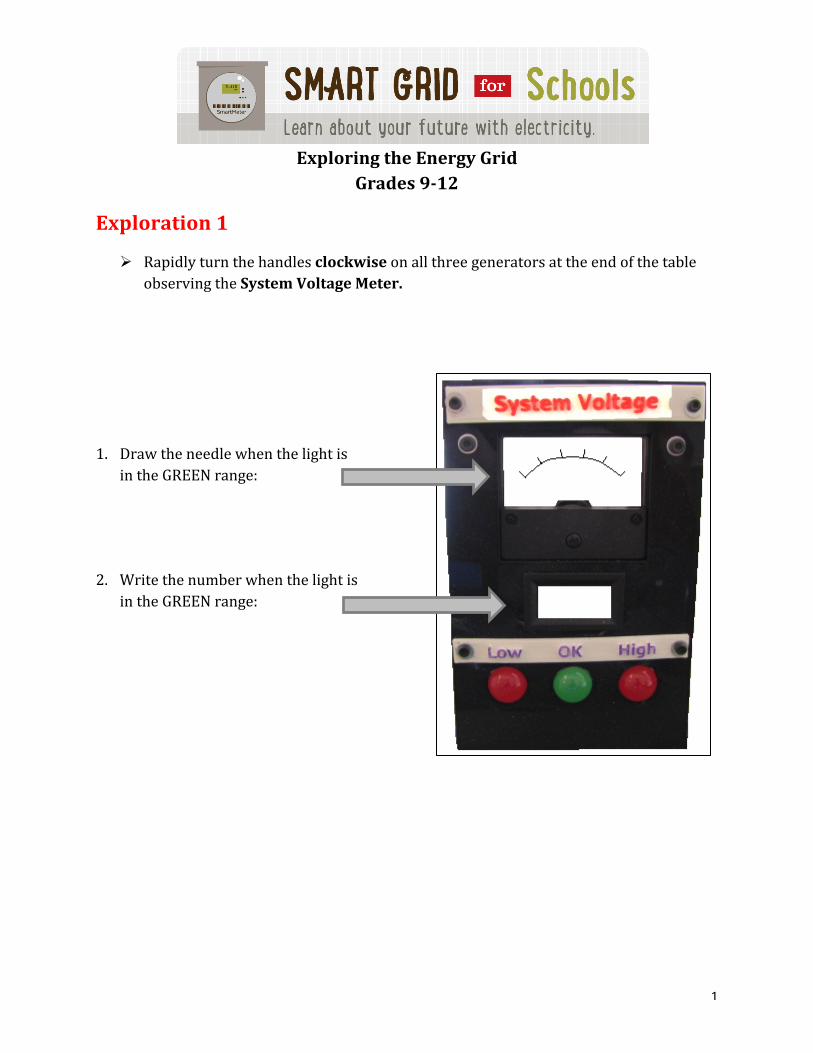
Ø Rapidly turn the handles clockwise on all three generators at the end of the table observing the System Voltage Meter.
1. Draw the needle when the light is in the GREEN range:
2. Write the number when the light is in the GREEN range:

2
Discussion 1
In 1831 Michael Faraday discovered one of the fundamental principles of electromagnetism. It is called Faraday’s Law. His law explains how electricity and magnetism interact, and forms the basis for modern electric motors and generators. Electric generators convert kinetic (motion) energy into electrical energy.
Study the generator to determine its working parts and read the diagrams on the sides of the tables to help you answer the discussion questions.
1. Draw a line to connect the parts of a generator to its name:
Hand crank
Drive belt
Stator
Rotor
Commutator
Brushes
Output terminals
2. What investigation do you think that Michael Faraday was probably doing when he first discovered his Law?
3. Explain how you think the generator is producing electricity.
4. What is the part of the generator that spins rapidly on the inside of the generator?
5. What is around the outside of the spinning rotor?
6. What is the purpose of the commutator?
7. What is the purpose of the brushes?
3
Exploration 2
Ø Make sure the Smart Grid Enable Switch is off and use the Smart Grid Table Wiring Directions located on the table to connect the power companies to the customers.
1. After you have wired the table crank the three generators rapidly, observing how the Low, OK, and High voltage outputs affects the building lights. Describe the connection between the System Voltage and buildings:
2. In the real world, the voltage on the electric grid must be maintained within a very narrow range. In this model electric grid, the voltage must be maintained at approximately 6.5 – 9.5 Volts in order to keep the customers’ lights on. What happens if you use just one of the generators?
3. Different parts of the grid affect a building’s power source. Describe what happens when you flip the bypass switch on the back of the SmartGrid box and disconnect any one wire.
4. With the wire disconnected turn the Smart Grid Enable Switch ON! Explain the connection between the Smart Grid Panel and the buildings:
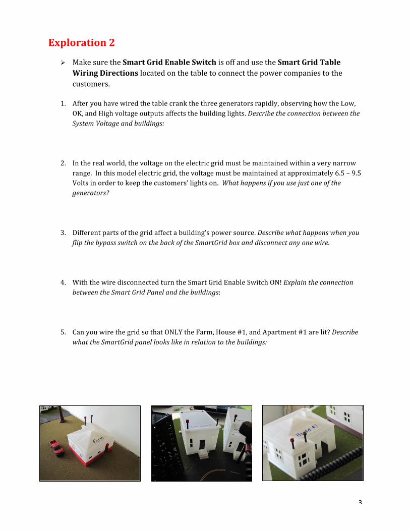
5. Can you wire the grid so that ONLY the Farm, House #1, and Apartment #1 are lit? Describe what the SmartGrid panel looks like in relation to the buildings:
4
Discussion 2
1. What do the green lights on the Smart Grid Control Panel tell you?
2. What do the red lights on the Smart Grid Control Panel tell you?
3. How does a utility company with standard meters (no SmartGrid) find out if a wire is broken or disconnected?
4. How do they determine which wire is broken?
5. How does a utility company with Smart Meters (with SmartGrid) find out if a wire is broken or disconnected?
6. How do they determine which wire is broken?
Reconnect all the buildings to the grid.
Apply It! Sometimes electricity goes off because of storm damage to transmission lines.
1. Has the electricity ever gone off at your home? 2. How long was it off?
Ø Turn the Smart Grid Switch OFF Ø A storm hit your area causing the power to go out in your neighborhood. Ask your
teacher (or someone else) to cause a problem in your grid. 3. Keeping the SmartGrid off, describe how you found and fixed the problems:
Ø Turn the Smart Grid Switch ON Ø Another storm hit your neighborhood. Ask your teacher (or someone else) to cause
problem in your grid. 4. With the SmartGrid on, describe how you found and fixed the problems:
5. How do you think the Smart Grid help utility companies?
6. How do you think the Smart Grid help customers?
5
Expanding
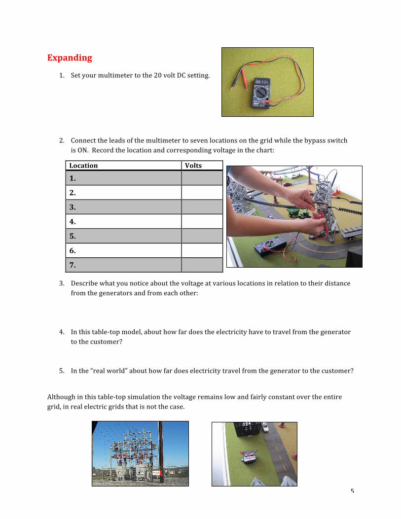
1. Set your multimeter to the 20 volt DC setting.
2. Connect the leads of the multimeter to seven locations on the grid while the bypass switch is ON. Record the location and corresponding voltage in the chart:
3. Describe what you notice about the voltage at various locations in relation to their distance from the generators and from each other:
4. In this table-‐top model, about how far does the electricity have to travel from the generator to the customer?
5. In the “real world” about how far does electricity travel from the generator to the customer?
Although in this table-‐top simulation the voltage remains low and fairly constant over the entire grid, in real electric grids that is not the case.
Location Volts
1. 2. 3. 4. 5. 6. 7.

6
Electrical power coming out of the real generator is at a relatively low voltage. Low voltage is not very efficient for transmission over large distances, so the voltage has to be “stepped up.” Typical high voltage power lines operate between 138,000 and 765,000 volts. When entering into a city, the voltage is typically stepped down to approximately 10,000 volts. In your neighborhood, it is stepped down again to two lines of 120 volts each. That is why most of your appliances are 120 volts and some, like the dryer, furnace, water heater, and oven operate on 240 volts. In many European countries, household voltage is 220 volts.
Besides describing generators, Faraday’s Law can be used to describe transformers. A transformer is used to change voltage in an electrical system. It has two coils of wire that are wrapped around a core, which is typically iron. When electricity flows in one coil, it “induces” electricity to flow in the other. The side that has more “turns” (loops) of wire has the higher voltage. In this way, voltage can be stepped up for long-‐distance transmission, and stepped down for distribution in neighborhoods.
Primary coil (or “primary winding”) Secondary coil (or “secondary winding”)
This is the side where the electricity “goes in” This is the output
6. Design a transformer that will change one voltage to another. Remember, even the smaller of the two coils can still have over 100 feet of wire.

7
7. Label the following diagram:
1. Why must the voltage of the electricity coming out of the power plant be “stepped up”?
2. In a step up transformer, which side has more wire, the primary coil or the secondary coil?
3. In a step down transformer, which side has more wire, the primary coil or the secondary coil?
4. If the output of a step up transformer has double the input voltage, how would you expect the lengths of wire in the primary and secondary coils to compare?
7. Design a transformer that has an input voltage of 12 volts and an output of 3 volts. Remember, even the smaller coil probably has well over 300 turns of wir