Single Stage Compressor Control · Minimum IGV fallback on IGV position fault Dynamic compressor...
190
Single Stage Compressor Control Catalog Numbers 1711-P02NSSCCN12600C, 1711-P02NSSCCN4X600C, 1711-P02NSSCCN121000C, 1711-P02NSSCCN4X1000C User Manual
Transcript of Single Stage Compressor Control · Minimum IGV fallback on IGV position fault Dynamic compressor...

Single Stage Compressor ControlCatalog Numbers 1711-P02NSSCCN12600C, 1711-P02NSSCCN4X600C, 1711-P02NSSCCN121000C, 1711-P02NSSCCN4X1000C
User Manual

Important User Information
Solid-state equipment has operational characteristics differing from those of electromechanical equipment. Safety Guidelines for the Application, Installation and Maintenance of Solid State Controls (publication SGI-1.1 available from your local Rockwell Automation® sales office or online at http://www.rockwellautomation.com/literature/) describes some important differences between solid-state equipment and hard-wired electromechanical devices. Because of this difference, and also because of the wide variety of uses for solid-state equipment, all persons responsible for applying this equipment must satisfy themselves that each intended application of this equipment is acceptable.
In no event will Rockwell Automation, Inc. be responsible or liable for indirect or consequential damages resulting from the use or application of this equipment.
The examples and diagrams in this manual are included solely for illustrative purposes. Because of the many variables and requirements associated with any particular installation, Rockwell Automation, Inc. cannot assume responsibility or liability for actual use based on the examples and diagrams.
No patent liability is assumed by Rockwell Automation, Inc. with respect to use of information, circuits, equipment, or software described in this manual.
Reproduction of the contents of this manual, in whole or in part, without written permission of Rockwell Automation, Inc., is prohibited.
Throughout this manual, when necessary, we use notes to make you aware of safety considerations.
Allen-Bradley, CompactLogix, PanelView Plus Compact, Rockwell Software, Rockwell Automation, and TechConnect are trademarks of Rockwell Automation, Inc.
Trademarks not belonging to Rockwell Automation are property of their respective companies.
WARNING: Identifies information about practices or circumstances that can cause an explosion in a hazardous environment, which may lead to personal injury or death, property damage, or economic loss.
ATTENTION: Identifies information about practices or circumstances that can lead to personal injury or death, property damage, or economic loss. Attentions help you identify a hazard, avoid a hazard, and recognize the consequence.
SHOCK HAZARD: Labels may be on or inside the equipment, for example, a drive or motor, to alert people that dangerous voltage may be present.
BURN HAZARD: Labels may be on or inside the equipment, for example, a drive or motor, to alert people that surfaces may reach dangerous temperatures.
IMPORTANT Identifies information that is critical for successful application and understanding of the product.

Table of Contents
Preface Who Should Use this Manual . . . . . . . . . . . . . . . . . . . . . . . . . . . . . . . . . . . . . . . 7Additional Resources . . . . . . . . . . . . . . . . . . . . . . . . . . . . . . . . . . . . . . . . . . . . . . . 7
Chapter 1Introduction Product Description. . . . . . . . . . . . . . . . . . . . . . . . . . . . . . . . . . . . . . . . . . . . . . . . 9
Application Overview . . . . . . . . . . . . . . . . . . . . . . . . . . . . . . . . . . . . . . . . . . . . . . 9
Chapter 2Single Stage Compressor Controller Installation
Single Stage Compressor Controller Components . . . . . . . . . . . . . . . . . . 13Mechanical Installation . . . . . . . . . . . . . . . . . . . . . . . . . . . . . . . . . . . . . . . . . . . 14
Electrostatic Precautions . . . . . . . . . . . . . . . . . . . . . . . . . . . . . . . . . . . . . . 14Unpack. . . . . . . . . . . . . . . . . . . . . . . . . . . . . . . . . . . . . . . . . . . . . . . . . . . . . . 14Inspection . . . . . . . . . . . . . . . . . . . . . . . . . . . . . . . . . . . . . . . . . . . . . . . . . . . 14Environmental/Location Requirements . . . . . . . . . . . . . . . . . . . . . . . . 15Tools . . . . . . . . . . . . . . . . . . . . . . . . . . . . . . . . . . . . . . . . . . . . . . . . . . . . . . . . 15Mount the Enclosure . . . . . . . . . . . . . . . . . . . . . . . . . . . . . . . . . . . . . . . . . 15
Power Distribution and Grounding. . . . . . . . . . . . . . . . . . . . . . . . . . . . . . . . 16Single Stage Compressor Controller Power Up . . . . . . . . . . . . . . . . . . . . . 17
Chapter 3SSCC Hardware Description Controller . . . . . . . . . . . . . . . . . . . . . . . . . . . . . . . . . . . . . . . . . . . . . . . . . . . . . . . 19
Digital Inputs . . . . . . . . . . . . . . . . . . . . . . . . . . . . . . . . . . . . . . . . . . . . . . . . 20Digital Outputs . . . . . . . . . . . . . . . . . . . . . . . . . . . . . . . . . . . . . . . . . . . . . . 21Analog Inputs . . . . . . . . . . . . . . . . . . . . . . . . . . . . . . . . . . . . . . . . . . . . . . . . 22Analog Outputs . . . . . . . . . . . . . . . . . . . . . . . . . . . . . . . . . . . . . . . . . . . . . . 23PanelView Plus Compact Graphic Terminal . . . . . . . . . . . . . . . . . . . . 24
Chapter 4Human Machine Interface Activate the HMI7 . . . . . . . . . . . . . . . . . . . . . . . . . . . . . . . . . . . . . . . . . . . . . . . 25
Navigation . . . . . . . . . . . . . . . . . . . . . . . . . . . . . . . . . . . . . . . . . . . . . . . . . . . . . . 27Navigation Toolbar. . . . . . . . . . . . . . . . . . . . . . . . . . . . . . . . . . . . . . . . . . . 29Operator Screen Overview . . . . . . . . . . . . . . . . . . . . . . . . . . . . . . . . . . . . 30Maintenance Screen Overview. . . . . . . . . . . . . . . . . . . . . . . . . . . . . . . . . 32Alarms Screen Overview . . . . . . . . . . . . . . . . . . . . . . . . . . . . . . . . . . . . . . 33Warnings Screen Overview. . . . . . . . . . . . . . . . . . . . . . . . . . . . . . . . . . . . 34Trend Select Screen Overview . . . . . . . . . . . . . . . . . . . . . . . . . . . . . . . . . 34Interlocks Screen Overview . . . . . . . . . . . . . . . . . . . . . . . . . . . . . . . . . . . 35Permissives Screen Overview . . . . . . . . . . . . . . . . . . . . . . . . . . . . . . . . . . 36Help Screen Overview . . . . . . . . . . . . . . . . . . . . . . . . . . . . . . . . . . . . . . . . 37
HMI Security . . . . . . . . . . . . . . . . . . . . . . . . . . . . . . . . . . . . . . . . . . . . . . . . . . . . 38User Login. . . . . . . . . . . . . . . . . . . . . . . . . . . . . . . . . . . . . . . . . . . . . . . . . . . 39User Logout . . . . . . . . . . . . . . . . . . . . . . . . . . . . . . . . . . . . . . . . . . . . . . . . . 41Change the User Password . . . . . . . . . . . . . . . . . . . . . . . . . . . . . . . . . . . . 41
HMI Functions with Security Privileges. . . . . . . . . . . . . . . . . . . . . . . . . . . . 43
Rockwell Automation Publication 1711-UM002A-EN-P - September 2012 3

Table of Contents
Chapter 5SSCC Configuration Parameter Lists. . . . . . . . . . . . . . . . . . . . . . . . . . . . . . . . . . . . . . . . . . . . . . . . . . . 51
01: AIN - Compressor Flow . . . . . . . . . . . . . . . . . . . . . . . . . . . . . . . . . . . 5302: AIN - Suction Pressure . . . . . . . . . . . . . . . . . . . . . . . . . . . . . . . . . . . . 5403: AIN - Discharge Pressure . . . . . . . . . . . . . . . . . . . . . . . . . . . . . . . . . . 5504: AIN - Auxiliary Control Signal . . . . . . . . . . . . . . . . . . . . . . . . . . . . . 5605: AIN - Suction Temperature. . . . . . . . . . . . . . . . . . . . . . . . . . . . . . . . 5706: AIN - Discharge Temperature. . . . . . . . . . . . . . . . . . . . . . . . . . . . . . 5807: AIN - Multi-use Signal A . . . . . . . . . . . . . . . . . . . . . . . . . . . . . . . . . . 5908: AIN - Multi-use Signal B. . . . . . . . . . . . . . . . . . . . . . . . . . . . . . . . . . . 6009: Digital Input Channel Configuration . . . . . . . . . . . . . . . . . . . . . . . 6110: Digital Output Channel Configuration . . . . . . . . . . . . . . . . . . . . . 6311: Compressor Configuration Information . . . . . . . . . . . . . . . . . . . . 6312: Surge Map Definition . . . . . . . . . . . . . . . . . . . . . . . . . . . . . . . . . . . . . 6513: Surge and Margin Configuration . . . . . . . . . . . . . . . . . . . . . . . . . . . 6614: Run and Load Configuration. . . . . . . . . . . . . . . . . . . . . . . . . . . . . . . 6815: Anti-Surge Control General Configuration . . . . . . . . . . . . . . . . . 6916: ASC Primary PID Loop . . . . . . . . . . . . . . . . . . . . . . . . . . . . . . . . . . . 7017: ASC Primary PID Loop - Adaptive Integral . . . . . . . . . . . . . . . . . 7218: ASC Primary PID Loop - Adaptive Proportional . . . . . . . . . . . . 7319: ASC Secondary PID Loop . . . . . . . . . . . . . . . . . . . . . . . . . . . . . . . . . 7420: Capacity Control General Configuration . . . . . . . . . . . . . . . . . . . 7621: Capacity Primary PID Loop. . . . . . . . . . . . . . . . . . . . . . . . . . . . . . . . 7822: Capacity Secondary PID Loop . . . . . . . . . . . . . . . . . . . . . . . . . . . . . 8023: Anti-Surge - Capacity Decoupling Configuration . . . . . . . . . . . . 8224: AINs - Substitute PV . . . . . . . . . . . . . . . . . . . . . . . . . . . . . . . . . . . . . . 8325: DINs - Substitute PV . . . . . . . . . . . . . . . . . . . . . . . . . . . . . . . . . . . . . . 8426: Reserved for Future Use . . . . . . . . . . . . . . . . . . . . . . . . . . . . . . . . . . . 8427: Interlock Bypassable Configuration. . . . . . . . . . . . . . . . . . . . . . . . . 8528: Permissive Bypassable Configuration . . . . . . . . . . . . . . . . . . . . . . . 8629: Modbus Serial Port Configuration. . . . . . . . . . . . . . . . . . . . . . . . . . 8730: Application (HMI Configuration) . . . . . . . . . . . . . . . . . . . . . . . . . 88
Parameter List Configuration . . . . . . . . . . . . . . . . . . . . . . . . . . . . . . . . . . . . . 89Parameter Configuration Screen Overview . . . . . . . . . . . . . . . . . . . . . 90Parameter List Actions . . . . . . . . . . . . . . . . . . . . . . . . . . . . . . . . . . . . . . . . 91
Interlock and Permissive Customization . . . . . . . . . . . . . . . . . . . . . . . . . . . 93Interlock Configuration Screen . . . . . . . . . . . . . . . . . . . . . . . . . . . . . . . . 94Permissive Configuration Screen . . . . . . . . . . . . . . . . . . . . . . . . . . . . . . . 95
Chapter 6SSCC Operation Operation Screen Details. . . . . . . . . . . . . . . . . . . . . . . . . . . . . . . . . . . . . . . . . . 97
Compressor Overview . . . . . . . . . . . . . . . . . . . . . . . . . . . . . . . . . . . . . . . . 97Compressor Map . . . . . . . . . . . . . . . . . . . . . . . . . . . . . . . . . . . . . . . . . . . . 101Margin Control . . . . . . . . . . . . . . . . . . . . . . . . . . . . . . . . . . . . . . . . . . . . . 103Anti-Surge Control PID Loops Overview. . . . . . . . . . . . . . . . . . . . . . 104Capacity Control PID Loops Overview. . . . . . . . . . . . . . . . . . . . . . . . 106
4 Rockwell Automation Publication 1711-UM002A-EN-P - September 2012

Table of Contents
Checking Interlocks, Permissives, and Warnings . . . . . . . . . . . . . . . . . . . 107Interlocks. . . . . . . . . . . . . . . . . . . . . . . . . . . . . . . . . . . . . . . . . . . . . . . . . . . 107Permissives . . . . . . . . . . . . . . . . . . . . . . . . . . . . . . . . . . . . . . . . . . . . . . . . . 112Warnings . . . . . . . . . . . . . . . . . . . . . . . . . . . . . . . . . . . . . . . . . . . . . . . . . . . 115
Compressor Start and Stop . . . . . . . . . . . . . . . . . . . . . . . . . . . . . . . . . . . . . . 118Compressor Running Determination . . . . . . . . . . . . . . . . . . . . . . . . . . . . . 120Compressor Load/Unload . . . . . . . . . . . . . . . . . . . . . . . . . . . . . . . . . . . . . . . 121Device Faceplates . . . . . . . . . . . . . . . . . . . . . . . . . . . . . . . . . . . . . . . . . . . . . . . 122
Accessing Device Faceplates . . . . . . . . . . . . . . . . . . . . . . . . . . . . . . . . . . 128Device Names and Device Selector . . . . . . . . . . . . . . . . . . . . . . . . . . . . 130Analog Input Device Faceplate . . . . . . . . . . . . . . . . . . . . . . . . . . . . . . . 132Analog Output Device Faceplate . . . . . . . . . . . . . . . . . . . . . . . . . . . . . 134Digital Input Device Faceplate . . . . . . . . . . . . . . . . . . . . . . . . . . . . . . . 137Digital Output Device Faceplate . . . . . . . . . . . . . . . . . . . . . . . . . . . . . 139PID Loop Faceplate . . . . . . . . . . . . . . . . . . . . . . . . . . . . . . . . . . . . . . . . . 141Compressor Details Faceplate . . . . . . . . . . . . . . . . . . . . . . . . . . . . . . . . 146
Trends . . . . . . . . . . . . . . . . . . . . . . . . . . . . . . . . . . . . . . . . . . . . . . . . . . . . . . . . . 153Using the Trend Detail Screen. . . . . . . . . . . . . . . . . . . . . . . . . . . . . . . . 157
Chapter 7Modbus Interface Serial Port Configuration . . . . . . . . . . . . . . . . . . . . . . . . . . . . . . . . . . . . . . . . 159
Modbus Holding Registers. . . . . . . . . . . . . . . . . . . . . . . . . . . . . . . . . . . . . . . 160
Chapter 8Troubleshooting System Power . . . . . . . . . . . . . . . . . . . . . . . . . . . . . . . . . . . . . . . . . . . . . . . . . . . 163
Hardware Status . . . . . . . . . . . . . . . . . . . . . . . . . . . . . . . . . . . . . . . . . . . . . . . . 164Controller Status . . . . . . . . . . . . . . . . . . . . . . . . . . . . . . . . . . . . . . . . . . . . 165Controller Major and Minor Fault Status . . . . . . . . . . . . . . . . . . . . . 167PanelView Maintenance . . . . . . . . . . . . . . . . . . . . . . . . . . . . . . . . . . . . . 168
I/O Modules . . . . . . . . . . . . . . . . . . . . . . . . . . . . . . . . . . . . . . . . . . . . . . . . . . . 168Digital Input Module Detail. . . . . . . . . . . . . . . . . . . . . . . . . . . . . . . . . . 170Digital Output Module Detail . . . . . . . . . . . . . . . . . . . . . . . . . . . . . . . . 170Analog Input Module Detail . . . . . . . . . . . . . . . . . . . . . . . . . . . . . . . . . 171Analog Output Module Detail . . . . . . . . . . . . . . . . . . . . . . . . . . . . . . . 172
Alarms . . . . . . . . . . . . . . . . . . . . . . . . . . . . . . . . . . . . . . . . . . . . . . . . . . . . . . . . . 172Managing Alarms . . . . . . . . . . . . . . . . . . . . . . . . . . . . . . . . . . . . . . . . . . . 173Alarm Example. . . . . . . . . . . . . . . . . . . . . . . . . . . . . . . . . . . . . . . . . . . . . . 177
Configuration Errors . . . . . . . . . . . . . . . . . . . . . . . . . . . . . . . . . . . . . . . . . . . . 179Startup or Operating Issues . . . . . . . . . . . . . . . . . . . . . . . . . . . . . . . . . . . . . . 180
Index
Rockwell Automation Publication 1711-UM002A-EN-P - September 2012 5

Table of Contents
6 Rockwell Automation Publication 1711-UM002A-EN-P - September 2012

Preface
This manual provides a product and application overview, installation instructions, hardware description, Human Machine Interface (HMI) operation instructions, configuration instructions, controller operation instructions, Modbus configuration instructions, and troubleshooting information for the Single Stage Compressor Controller.
Who Should Use this Manual This manual is intended for qualified personnel responsible for installing and operating the Rockwell Automation Single Stage Compressor Controller (SSCC). You should have previous experience with, and an understanding of, electrical terminology, procedures, required troubleshooting equipment, equipment protection procedures and methods, and safety precautions. See safety related practices contained in publication NFPA 70E, Standard for Electrical Safety in the Work Place.
Additional Resources These documents contain additional information concerning related products from Rockwell Automation.
You can view or download publications athttp:/www.rockwellautomation.com/literature/. To order paper copies of technical documentation, contact your local Allen-Bradley distributor or Rockwell Automation sales representative.
Resource Description
CompactLogix™ Controllers Specifications Technical Data, publication 1769-TD005.
Provides controller specifications.
CompactLogix Packaged Controllers Quick Start and User Manual, publication IASIMP-QS010.
Procedures for using your CompactLogix packaged controller as well as additional reference information.
Logix5000 Controllers Common Procedures, publication 1756-PM001.
Provides information on developing projects for Logix5000 controllers.
PanelView™ Plus Compact Terminals User Manual, publication 2711PC-UM001.
Provides instructions for installing, configuring, and operating PanelView Plus Compact terminals.
Industrial Automation Wiring and Grounding Guidelines, publication 1770-4.1
Provides general guidelines for installing a Rockwell Automation industrial system.
Product Certifications website, http://www.ab.com Provides declarations of conformity, certificates, and other certification details.
Rockwell Automation Publication 1711-UM002A-EN-P - September 2012 7

Preface
Notes:
8 Rockwell Automation Publication 1711-UM002A-EN-P - September 2012

Chapter 1
Introduction
Product Description The Single Stage Compressor Controller (SSCC) from Rockwell Automation is a packaged solution providing anti-surge and capacity control for a single-stage centrifugal or axial gas compressor. The SSCC is an economical compressor controller providing advanced control algorithms allowing for safe and energy efficient operation across the compressors operating range.
Figure 1 - Typical Compressor Controls
Application Overview The SSCC utilizes a surge control algorithm which calculates a percent flow and determines the compressor’s head (simplified polytropic or pressure ratio). If the percent flow is not adequate for the compressor’s head, the recycle valve will be opened. The algorithm is used to generate a setpoint for the specialized PID loop. The surge control algorithm executes in less than 25 ms.
The following simplified functional block diagram illustrates the features of the algorithm. Secondary PID loop over-rides, and capacity control are not shown for clarity.
PIC
UIC
FT PT TT
PT TT
Anti-Surge Valve
Suction Valve (Capacity Control)
Compressor
Cooler
Rockwell Automation Publication 1711-UM002A-EN-P - September 2012 9

Chapter 1 Introduction
Figure 2 - Anti-surge Control Function Block Diagram
Functional aspects of the SSCC control strategy are summarized in the following table.
Table 1 - Application Function Summary
Q
Qmax
Td
Ts
Ps
Pd
m’
OP
OP
SP
PV
SVPID
OP
OP
Ps
Pd
m’
CLL
SLL
Hp
20 mA . . .4 mA
AO
OperatingPointCalc
AdaptiveTuning
OP Track
Margin Calc
Lookup Table
HeadCalc
OP Track
Surge Count
Feedback
Analog Out Loop 1
Function Features
Analog Input Processing
Channel usage configuration (not-used, used, and usage type)Engineering unit calculation of process value (PV), with linear or square-root extractionAbsolute value correction factor, for PVabs (Press & Temp signals)Under-range and over-range alarmsConfigurable PV high and low alarmsSubstitute PV mode to replace field signal with a substitute valueChannel health monitoring and reportingDevice faceplate on HMI
Digital Input Processing
Channel usage configuration (not-used, used)Input state (polarity of signal)Channel health monitoring and reportingDevice faceplate on HMI
Digital Output Processing
Output state (polarity of signal)Operator mode for field device testingChannel health monitoring and reportingDevice faceplate on HMI
10 Rockwell Automation Publication 1711-UM002A-EN-P - September 2012

Introduction Chapter 1
Analog Output Processing
Device action (air-to-open, air-to-close)Position monitoring optionOperator mode for field device testingChannel health monitoring and reportingDevice faceplate on HMI
Compressor Head Calculates the “head” of the compressor as simplified polytropic head (HpSim), pressure ratio (Pratio), and pressure rise (Prise)Choice of HpSim or Pratio as head type for the surge mapConfiguration error and calculation fault reporting
Operating Point Calculates the operating point (OP) as a normalized, compensated representation of flow, compensated to base conditions of the surge mapSupports four varieties of flow instrumentation for the compressor• Flow in suction• Flow in discharge, no cooling (inter-stage or upstream of flow)• Flow in discharge, downstream of inter-stage or discharge coolers• Alternate signal used in place of flow - special casesConfiguration error and calculation fault reporting
Surge Map 10-segment surge map defines the surge limit line (SLL)Minimum flow fallback strategy on head calculation faultOption for inlet guide vane (IGV) adjustment methodsMinimum IGV fallback on IGV position faultDynamic compressor map on human machine interface (HMI)
Surge Detection Compressor surge detection using:• Positional surge detection: OP falls below SLL• Rate-of-change surge: OP drops rapidly beyond configured limits• Incipient surge: Optional SurgeGard signal detection of impending surge
Control Margin Calculation of the control limit line (CLL) using configurable marginMargin based on offset and percentage methodsConvenient increment and decrement margin featuresAutomatic margin increment on surge detectionMinimum (base) and maximum margin limits
Operating Point Tracking
Calculates the surge control line (SCL) using OP tracking methodsAs OP increases above CLL, SCL tracks OP by a track marginWhen OP decreases back towards CLL, SCL decays at a track rateConfigurable max limit, and minimum limited by CLL
Adaptive Tuning Dynamic adjustment to PID loop tuning parameters (ASC primary PID loop) using configurable breakpoints and slopesWhen operating between breakpoints, tuning value is at base valueWhen operating beyond breakpoints, tuning value automatically adjusted based on slopes
PID Controls PID controller features:• Range configured automatically based on PV selection• Configurable setpoint management (track in manual, limits, rates)• PID control direction (direct, reverse)• Variety of tuning options• Manual mode override protection for anti-surge PID• PID faceplate on HMI
Min/Max Selector and Control/Track Management
When both the primary PID and a secondary (override) PID are configured, the configured min or max control signal is selectedNon-selected PID loop tracks the selected PID loop by marginControl/track mode reporting
Control Slew Rate and Override Limits
Control value (CV) features:• Minimum and maximum limits• Opening and closing slew rate limits• Override/tripped/not running value
Anti-Surge and Capacity Decoupling
Decoupling between anti-surge and capacity controlsPrevents capacity controls from driving compressor into surge
Function Features
Rockwell Automation Publication 1711-UM002A-EN-P - September 2012 11

Chapter 1 Introduction
Surge Test and Capture Built-in surge test methodsUsed to validate surge mapTraps operating data on surge detectionSurge point presented on compressor map
Interlock Management Four configurable external interlocks for compressor tripManagement of external and internal interlocks with first-out indicationConfigurable interlock bypass featuresCompressor trip output for interface to drive controller
Permissive Management
Four configurable external permissives for compressor ready-to-startManagement of external and internal permissives with first-out indicationConfigurable permissive bypass featuresReady-to-start output for interface to drive controller
Function Features
12 Rockwell Automation Publication 1711-UM002A-EN-P - September 2012

Chapter 2
Single Stage Compressor Controller Installation
Single Stage Compressor Controller Components
The Single State Compressor Controller (SSCC) is composed of the following components:
• Enclosure• CompactLogix controller • Digital inputs• Digital outputs• Analog inputs• Analog outputs• PanelView Plus HMI
All the SSCC required components are mounted, wired and installed inside the unit’s enclosure, from the factory. This section describes the steps for installation.
Figure 3 - SSCC Panel - Interior View
CompactLogix Controller
Internal Power Distribution
Power from AC or DC Source
DO Marshalling TerminalsDI, AI, and AO
Marshalling Terminals
PanelView Plus Mounted on Door Panel
Rockwell Automation Publication 1711-UM002A-EN-P - September 2012 13

Chapter 2 Single Stage Compressor Controller Installation
Mechanical Installation Electrostatic Precautions
The electronic components of these systems are susceptible to electrostatic discharge. Be sure to take the following precautions.
• Always wear an anti-static wrist strap (or equivalent) when handling any electrostatic sensitive components.
• All electrostatic sensitive components will be packaged in anti-static bags. Do not remove these components from these bags until you are ready to install them.
• Controller modules are especially sensitive to electrostatic discharge; pay special attention not to touch the module connectors or any exposed printed circuit board (PCB) components.
• Store all shipping materials, especially anti-static bags, to re-use if it becomes necessary to transport or ship any system components.
Unpack
All items must be removed from their packaging and checked against the packing list. Verify that all items are correct and contact Rockwell Automation if any discrepancies are found. Before unpacking any items, the packaging must be inspected for damage which may have occurred during shipment. See the “Inspection” section.
If any packaging is damaged, the package identifying marks (box number, crate number, etc.) must be noted and communicated to Rockwell Automation. The package must be stored in a suitable storage area in the condition it was received. Rockwell Automation will contact the shipping agent who may request to inspect the damage. The package must not be opened without the express written permission of Rockwell Automation.
Inspection
• Visually inspect the cabinets for mechanical damage, check the painted surfaces for scratches and abrasions.
• Check that the cabinet door opens and closes, and that all latches operate smoothly.
• Check all internal components against the detailed layout drawings, and be sure that these components were not damaged during shipment.
• Check cable assemblies to make sure they were not damaged during shipment. All wire ducts should be fitted with covers and all cable assemblies should be appropriately dressed with cable ties and/or spiral wrap.
14 Rockwell Automation Publication 1711-UM002A-EN-P - September 2012

Single Stage Compressor Controller Installation Chapter 2
Environmental/Location Requirements
To meet environmental requirements when installing the equipment, it should be installed in a room with an ambient temperature of -10…+50 °C (14…122 °F) with a relative humidity of 0% to 95% relative humidity, non-condensing; and the room must be provided with adequate lighting.
Tools
An adjustable wrench and socket set are required for panel installation.
Mount the Enclosure
1. Determine the mounting location and be sure it is able to support 31.8 kg (70 lb). Allow sufficient room above and below, or at the left and right sides, for cable exiting the enclosure, and for opening the door.
2. Mark the wall through the top of the slots in only the top two mounting key holes. Drill the necessary holes for the bolts.
3. Insert the bolts through the bottom two mounting key holes of the enclosure and into the wall. DO NOT tighten the bolts at this time.
4. Mark the wall through the holes in the top two mounting holes. Remove the enclosure from the wall, drill the necessary holes for the bolts, and re-hang the enclosure onto the bottom two bolts.
5. Insert bolts through the holes in the top two mounting holes of the enclosure and into the wall. Tighten all the bolts.
Rockwell Automation Publication 1711-UM002A-EN-P - September 2012 15

Chapter 2 Single Stage Compressor Controller Installation
Power Distribution and Grounding
System can be powered by 24V DC or 120V AC. Connect power to terminals shown in the supplied wiring drawings. Terminal locations are identified in this photograph.
There are two different ground connections that must be connected before power is applied to the system. The AC safety ground is for all exposed metal surfaces of cabinets, racks, chassis ground connections, etc. (All individual ground wiring interconnections are to be a minimum of 16 AWG, copper wire, green insulation). Instrument ground is for all DC analog/digital, signal cable shield wires. Reference ground wiring interconnections will be a minimum of 18 AWG, copper wire, green insulation, with yellow tracer.
Check for a good electrical AC safety ground connection. The electrical ground connection must be matched to the breakers or fuses used to protect the feeds to the system. Check the integrity of the connection and the gauge of the wire used, that it is sufficient to allow the breakers or fuses to trip.
Alternate DC SourcedPower Connection
(Regulated 24V DC)
Instrument Ground Connection AC Safety Ground Connection
AC Sourced Power Connection (100…240V AC)
ATTENTION: Good ground connections must be verified before any work can be carried out by any Rockwell Automation or client personnel. Failure to comply may cause serious injury.
16 Rockwell Automation Publication 1711-UM002A-EN-P - September 2012
Single Stage Compressor Controller Installation Chapter 2
Single Stage Compressor Controller Powerup
First time power up must be done in stages to guard against system-wide power distribution faults. The system’s power distribution must be verified against the power distribution drawings.
1. Switch all circuit breakers to the Off position and open all fuses.
2. Energize the 24V DC or 120V AC feed, and verify voltage at the main incoming terminals.
3. Close each 120V AC circuit breaker, one at a time, and verify that the corresponding power supply is energized.
4. Measure the output voltage of the power supply and verify it is delivering 24V DC.
5. Close each 24V DC fuse, one at a time, and verify the corresponding equipment receives 24V DC by measuring at the power terminals of the receiving equipment.
6. Close all 24V DC fuses, checking that the system powers-up as expected.
Rockwell Automation Publication 1711-UM002A-EN-P - September 2012 17

Chapter 2 Single Stage Compressor Controller Installation
Notes:
18 Rockwell Automation Publication 1711-UM002A-EN-P - September 2012

Chapter 3
SSCC Hardware Description
Controller The SSCC hardware and software platform is the 1769-L23E-QB1B CompactLogix system. The controller comes preconfigured with sixteen digital inputs and sixteen digital outputs. For the SSCC system, two expansion 1769-Series I/O modules are added for analog inputs (1769-IF8) and analog outputs (1769-OF4).
Figure 4 - CompactLogix Controller L23E
Rockwell Automation Publication 1711-UM002A-EN-P - September 2012 19

Chapter 3 SSCC Hardware Description
Digital Inputs
The SSCC has 16 digital inputs powered by 24V DC. All inputs are prewired from marshalling terminal blocks (TS1) to the module specific removable terminal blocks.
Table 2 - Digital Input Channel Assignment and Wiring
Notes:• Accessories (push buttons) for use on channels 1, 2, and 3 are not provided
with the unit; the customer must purchase and install accessories separately, as required. For each of these signals, the equivalent functionality is provided on the graphic screens of the unit’s HMI.
• Digital input signal function polarity is configurable for each channel.• Each channel is configurable for “use” or “not-used.” Signals present on
channels configured as “not-used” are ignored.
Input Description TS1
Channel 0 Compressor Running contact 1-2
Channel 1 Reset push button 3-4
Channel 2 Load Compressor request push button 5-6
Channel 3 Unload Compressor request push button 7-8
Channel 4 Reserved for future use 9-10
Channel 5 Reserved for future use 11-12
Channel 6 Reserved for future use 13-14
Channel 7 Reserved for future use 15-16
Channel 8 External Ready-to-start Permissive 1 17-18
Channel 9 External Ready-to-start Permissive 2 19-20
Channel 10 External Ready-to-start Permissive 3 21-22
Channel 11 External Ready-to-start Permissive 4 23-24
Channel 12 External Trip Interlock 1 25-26
Channel 13 External Trip Interlock 2 27-28
Channel 14 External Trip Interlock 3 29-30
Channel 15 External Trip Interlock 4 31-32
20 Rockwell Automation Publication 1711-UM002A-EN-P - September 2012

SSCC Hardware Description Chapter 3
Digital Outputs
The SSCC has 16 digital outputs powered by 24VDC. All outputs are prewired from marshalling terminal blocks (TS2) to the module specific removable terminal blocks.
Table 3 - Digital Output Channel Assignment and Wiring
Notes:• All digital output channels are 24V DC sourcing outputs.• Digital output signal function polarity is configurable per channel.• Compressor trip/interlock (channel 0) is intended for connection to the
compressor driver (motor, turbine, etc.) to shutdown the compressor.• Read-to-start permissive (channel 1) is intended for connection to the
compressor driver (motor, turbine, etc.) as a permissive to start the compressor.
Output Description TS2
Channel 0 Compressor Trip/Interlock 1-2
Channel 1 Surge Alarm 3-4
Channel 2 System Trouble Alarm 5-6
Channel 3 Ready-to-start Permissive 7-8
Channel 4 Compressor Running Status Indication 9-10
Channel 5 Compressor Loaded Status Indication 11-12
Channel 6 Reserved for future use 13-14
Channel 7 Reserved for future use 15-16
Channel 8 Reserved for future use 17-18
Channel 9 Reserved for future use 19-20
Channel 10 Reserved for future use 21-22
Channel 11 Reserved for future use 23-24
Channel 12 Reserved for future use 25-26
Channel 13 Reserved for future use 27-28
Channel 14 Reserved for future use 29-30
Channel 15 Reserved for future use 31-32
Rockwell Automation Publication 1711-UM002A-EN-P - September 2012 21

Chapter 3 SSCC Hardware Description
Analog Inputs
The SSCC has eight analog inputs (current 4…20 mA). All inputs are prewired from marshalling terminal blocks (TS1) to the module specific removable terminal blocks.
Table 4 - Analog Input Channel Assignment and Wiring
Notes:• Each channel has configurable engineering unit scaling, linearization type,
and alarm limits.• Flow, suction pressure and discharge pressure (channels 0, 1, and 2)
represent the minimum required signals for anti-surge control.• Temperatures (channels 4 and 5) are often optional, but are required when
flow is measured in discharge and the compressor has inter-stage cooling or discharge cooling upstream of flow measurement.
• SurgeGard for incipient surge detection is sold separately. Space is allocated in the panel for mounting and wiring to the system.
Input Description TS1 Configuration Options
Channel 0 Compressor Flow 33-34 Flow Transmitter located:Compressor Suction, orCompressor Discharge, or Alternate Signal when no Flow signal (consult factory for advice)
Channel 1 Suction Pressure 35-36 Pressure Transmitter in Compressor Suction
Channel 2 Discharge Pressure 37-38 Pressure Transmitter in Compressor Discharge
Channel 3 Auxiliary Control Signal 39-40 Auxiliary Process Transmitter. An optional signal that may be used for capacity control, or anti-surge override control
Channel 4 Suction Temperature 41-42 Temperature Transmitter in Compressor Suction
Channel 5 Discharge Temperature 43-44 Temperature Transmitter in Compressor Discharge
Channel 6 Multi-Use Signal A 45-46 Choose connection to:Anti-Surge Valve position Transmitter, orCapacity Valve / Inlet Guide Vane position Transmitter, orIncipient Surge (SurgeGard) signal
Channel 7 Multi-Use Signal B 47-48 Choose connection to:Anti-Surge Valve position Transmitter, orCapacity Valve / Inlet Guide Vane position Transmitter, orIncipient Surge (SurgeGard) signal
22 Rockwell Automation Publication 1711-UM002A-EN-P - September 2012

SSCC Hardware Description Chapter 3
Analog Outputs
The SSCC has four analog outputs (current 4…20 mA). All outputs are prewired from marshalling terminal blocks (TS1) to the module specific removable terminal blocks.
Table 5 - Analog Output Channel Assignment and Wiring
Note: For each analog output, the application control signal 0…100% open can be configured to actuate the device as air-to-open or air-to-close.
Input Description TS1 Device
Channel 0 Anti-Surge Control Valve 49-50 Typically Recycle Valve or Blow-Off Valve.
Channel 1 Capacity Control Device 51-52 Typically Suction Valve, Inlet Guide Vanes, Discharge Valve, or Cascade setpoint to Speed Controller.
Channel 2 Reserved for future 53-54 None
Channel 3 Reserved for future 55-56 None
Rockwell Automation Publication 1711-UM002A-EN-P - September 2012 23

Chapter 3 SSCC Hardware Description
PanelView Plus Compact Graphic Terminal
The SSCC is equipped with a PanelView Plus Compact color graphic terminal for a HMI. This device is used as the interface for operation and configuration of the SSCC. The HMI is installed on the door of the unit control panel and wiring for power and communication are provided from factory. The standard HMI is the PanelView Plus Compact 600 with 5.5 in. color touchscreen. The PanelView Plus Compact 1000 with 10.4 in. color touchscreen can be ordered as an option for the SSCC.
Figure 5 - PanelView Plus Compact 600 Graphic Terminal
Figure 6 - PanelView Plus Compact 1000 Graphic Terminal
24 Rockwell Automation Publication 1711-UM002A-EN-P - September 2012

Chapter 4
Human Machine Interface
The human machine interface (HMI) provides a single interface for configuration, operation, maintenance and troubleshooting the SCCC system. This chapter familiarizes you with these general features and how to access them. Further details are found later in this manual.
Activate the HMI The operator interface requires entry of an Activation Key ID to activate the HMI for use. Until the HMI has been successfully activated the HMI will only display the following screen.
Figure 7 - HMI Activation Screen
Each SSCC requires a unique, eight-character HMI activation Key ID. The Key ID can be provided from an Authorized Rockwell Automation agent. You will need to provide them the System Serial Number and Product ID Number as shown on your Activation screen.
Rockwell Automation Publication 1711-UM002A-EN-P - September 2012 25

Chapter 4 Human Machine Interface
Follow these steps to activate the HMI.
1. On the Activation screen, press the Enter Activation Key ID entry line.
The following keypad appears.
2. Enter the Key ID using the touch keypad.
Note: The characters in the Key ID are NOT case sensitive. Only enter the eight character ID. Do not enter any dashes, spaces, or other symbols. For example, if your agent provides the Key ID of 23F4-60BC, only enter the eight characters, 23F460BC (or 23f460bc), omitting the dash symbol.
If the Key ID you entered is not valid, the Activation screen remains on the HMI. In this case, verify the Key ID entered and correct if necessary. If activation problems continue, contact Rockwell Automation for further assistance.
If the Key ID is valid and the HMI activation is successful, the toolbar is displayed at the top of the screen and the Application Information screen appears.
26 Rockwell Automation Publication 1711-UM002A-EN-P - September 2012

Human Machine Interface Chapter 4
Navigation The HMI application facilitates user navigation through a centralized icon toolbar. The toolbar icons access the following eight main screens.
• Operator • Maintenance• Alarms• Warnings• Trends• Interlocks• Permissives• Help
Each of the main screens accesses additional screens that allow you to fully configure the SSCC. A navigational hierarchy is presented in Figure 8 on page 28.
Rockwell Automation Publication 1711-UM002A-EN-P - September 2012 27

Chapter 4 Human Machine Interface
Figure 8 - HMI Screens Navigational Hierarchy
ApplicationStart
OperatorScreen
MaintenanceScreen
AlarmScreen
WarningScreen
Trend SelectScreen
InterlockScreen
PermissiveScreen
HelpScreen
Parameter Configuration
Interlock Configuration
Permissive Configuration
HardwareStatus
Device Configuration
TrendDetail
I/OStatus
AnalogInput
AnalogOutput
DigitalInput
DigitalOutput
PID LoopFaceplate
CompressorDetails
Startup Screen Main Screens Popup ScreensPopup Screens
28 Rockwell Automation Publication 1711-UM002A-EN-P - September 2012

Human Machine Interface Chapter 4
Navigation Toolbar
Each main screen contains at least one page, where pages are equivalent to displays. In order to access a main screen, press the corresponding button on the upper navigation toolbar.
When a main screen contains multiple pages, a page navigation bar is presented at the bottom of the screen, as shown here. When the screen has only one page, the page navigation bar is not presented.
The number of pages is represented by the number of dots presented in the center of the navigation bar. The green dot indicates which page is presently shown on the screen.
Use the right arrow button to navigate forward and the left arrow button to navigate backwards through the pages of the screen. Navigation forward from the last screen returns to the first screen and vice versa.
Left Arrow Right ArrowNumber of Pages
Rockwell Automation Publication 1711-UM002A-EN-P - September 2012 29

Chapter 4 Human Machine Interface
Operator Screen Overview
From any main screen, press the home icon on the navigation toolbar to open the Operator screen. The Operator screen contains six pages for operations. When the Operator screen appears, the last viewed page is presented.
Table 6 - Operator Screen Pages
Page Example Screen(s) Description
1 Operator Screen – User Login Display Features:• Date and time of the HMI
Operational Features:
• Press to log in and obtain user security privileges
• Press to log off (return to Default user, with no security privileges)
2 Operator Screen – Compressor OverviewDisplay Features:• Signal values for all configured transmitters (AINs)• Anti-surge valve control value and location• Capacity control value and device type/location (if configured)• Overall unit status indicators (ready, trip, surge, run, load, trouble)
Operational Features:
• Press to load the compressor – security privilege required (O, S, M, or E)
• Press to unload the compressor – security privilege required (O, S, M, or E)
3 Operator Screen – Compressor MapDisplay Features:• Compressor map for Surge Limit Line (SLL), Control Limit Line (CLL) and Surge Control Line (SCL) with live Operating
Point (OP)• Anti-surge calculated values for Head, OP, SLL, Margin, CLL, SCL and Distance of OP from Control Limit Line• Summary of anti-surge and capacity PID loop outputs and control values (for configured loops)
Operational Features:
• Press the to open the Compressor Details popup screen for additional anti-surge information and settings
30 Rockwell Automation Publication 1711-UM002A-EN-P - September 2012

Human Machine Interface Chapter 4
4 Operator Screen – Margin Control Display Features:• Anti-surge margin information
Operational Features:
• Press (margin increment) and (margin decrement) to adjust margin – security privilege required (O, S, M, or E)
• Modify Base, Max Margin, and Margin Adjustment - security privilege required (M, E, or A)
5 Operator Screen – Anti-Surge Control PID Loops Overview Display Features:• Overview of Anti-surge control PID loops (PV, SP, Output, Mode)• Anti-surge secondary (Override) PID loop is only shown when configured.
Operational Features:
• Press to open individual PID loop faceplates for detailed PID loop operation and tuning
6 Operator Screen – Capacity Control PID Loops OverviewDisplay Features:• Overview of Capacity Control PID Loops (PV, SP, Output, Mode)• Capacity PID loops are only shown when configured
Operational Features:
• Press to open individual PID loop faceplates for detailed PID loop operation and tuning
Table 6 - Operator Screen Pages (Continued)
Page Example Screen(s) Description
Rockwell Automation Publication 1711-UM002A-EN-P - September 2012 31

Chapter 4 Human Machine Interface
Maintenance Screen Overview
From any main screen, press the Maintenance icon on the navigation toolbar to open the Maintenance screen. The Maintenance screen has three pages for configuration and maintenance activities. When the Maintenance screen opens, the last viewed page is presented.
Table 7 - Maintenance Screen Pages
Page Example Screen(s) Description
1 Maintenance Screen – Configuration and Settings Display Features:• Access to configuration, device settings, and hardware status monitoring• Bypass interlocks and permissives only shown if configured
Operational Features:
• Press to access Parameter Configuration popup screen
• Press to access Interlocks Configuration popup screen
• Press to access Permissives Configuration popup screen
• Press to access Hardware popup screen to access controller and PanelView Plus status information
• Press to disable bypass for interlocks and permissives – security privilege required (M, E, or A)
• Press to enable bypass for the configured Interlocks and permissives – security privilege required (M, E, or A)
• Use to choose a device and press to open a Device Detail popup (for AIN, DIN, AOUT, DOUT, PID Loop, and Compressor Details)
2 Maintenance Screen – Change Password Display Features:• Access to login/logout and change passwords
Operational Features:
• Press to log in with user security privileges
• Press to log off (return to default user, with no security privileges)
• Press to change the password for the current user – security privilege required (O, S, M, E, or A as applicable)
3 Maintenance Screen – Localization Display Features:• Language selection• Units of measure selection
Operational Features: • Press the flag that represents the language choice for the HMI• Press for either Primary or Secondary units – security privilege required (E or A). This selection switches the text
for Units between the user configured primary and secondary units text strings.
32 Rockwell Automation Publication 1711-UM002A-EN-P - September 2012
Human Machine Interface Chapter 4
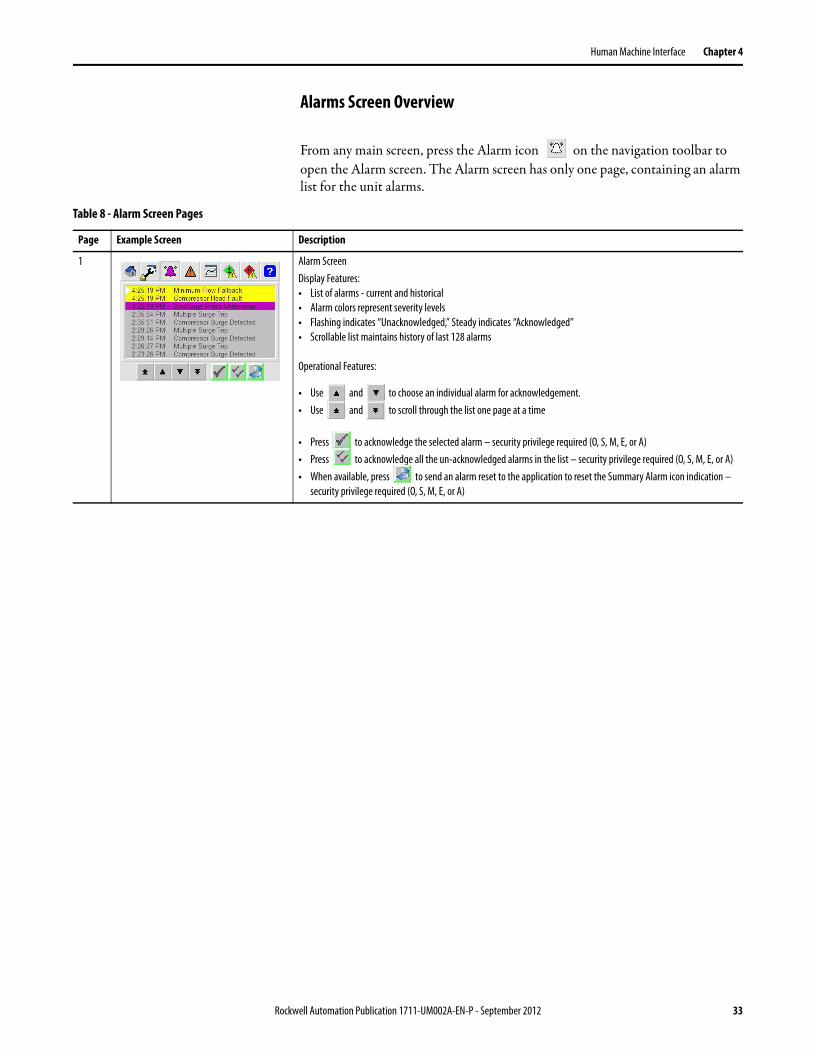
Alarms Screen Overview
From any main screen, press the Alarm icon on the navigation toolbar to open the Alarm screen. The Alarm screen has only one page, containing an alarm list for the unit alarms.
Table 8 - Alarm Screen Pages
Page Example Screen Description
1 Alarm ScreenDisplay Features:• List of alarms - current and historical• Alarm colors represent severity levels• Flashing indicates “Unacknowledged,” Steady indicates “Acknowledged”• Scrollable list maintains history of last 128 alarms
Operational Features:
• Use and to choose an individual alarm for acknowledgement.• Use and to scroll through the list one page at a time
• Press to acknowledge the selected alarm – security privilege required (O, S, M, E, or A)• Press to acknowledge all the un-acknowledged alarms in the list – security privilege required (O, S, M, E, or A)• When available, press to send an alarm reset to the application to reset the Summary Alarm icon indication –
security privilege required (O, S, M, E, or A)
Rockwell Automation Publication 1711-UM002A-EN-P - September 2012 33

Chapter 4 Human Machine Interface
Warnings Screen Overview
From any main screen, press the Warnings icon on the navigation toolbar to open the Warnings screen. The Warnings screen has two pages for alerting the user regarding important errors or other operating condition. When the Warnings screen opens, the last viewed page is presented to the user.
Trend Select Screen Overview
From any main screen, press the Trend icon on the navigation toolbar to open the Trend Select screen. The Trend Select screen has only one page, containing a list of trend groups.
Table 9 - Warnings Screen Pages
Page Example Screen Description
1 Warnings Screen – Level 1: Preventing Operation Display Features:• Level 1 warnings are presented by an orange color• The Warning icon on the top navigation toolbar will change color to alert the operator when a warning condition is
present
Operational Features: • No user operations required from this screen
2 Warnings Screen – Level 2: Function Disabled/Bypassed Display Features:• Level 2 warnings are presented by an yellow color• The Warning icon on the top navigation toolbar will change color to alert the operator when a warning condition is
present
Operational Features: • No user operations required from this screen
Table 10 - Trend Select Screen Pages
Page Example Screen Description
1 Trend Select ScreenDisplay Features:• Trend Group selector
Operational Features: • Use and to choose the desired trend group.
• Press to open the Trend Detail popup screen for the chosen trend group
34 Rockwell Automation Publication 1711-UM002A-EN-P - September 2012

Human Machine Interface Chapter 4
Interlocks Screen Overview
From any main screen, press the Interlock icon on the navigation toolbar to open the Interlocks screen. The Interlocks screen has two pages, presenting the condition of the compressor interlocks.
Table 11 - Interlocks Screen Pages
Page Example Screen Description
1 Interlocks Screen – Internal Interlocks Display Features:• Internal Interlocks organized on page one• First-Out interlock displayed in yellow color
Operational Features: • When available, press to reset latched interlocks that have cleared – security privilege required (O, S, M, E, or A)
2 Interlocks Screen – External Interlocks Display Features:• External interlocks organized on page two• First-Out interlock displayed in yellow color
Operational Features: • When available, press to reset latched interlocks that have cleared – security privilege required (O, S, M, E, or A)
Rockwell Automation Publication 1711-UM002A-EN-P - September 2012 35

Chapter 4 Human Machine Interface
Permissives Screen Overview
From any main screen, press the Permissive icon on the navigation toolbar to open the Permissives screen. The Permissives screen has 2 pages, presenting the condition of the compressor permissives.
Table 12 - Permissives Screen Pages
Page Example Screen Description
1 Permissives Screen – Internal Logic Permissives Display Features:• Internal permissives organized on page one• First-out permissive displayed in yellow color
Operational Features: • Permissives are non-latching so use of Reset button is not required (O, S, M, E, or A)
2 Permissives Screen – External Permissives Display Features:• External permissives organized on page two• First-Out permissive displayed in yellow color
Operational Features: • Permissives are non-latching so use of Reset button is not required (O, S, M, E, or A)
36 Rockwell Automation Publication 1711-UM002A-EN-P - September 2012

Human Machine Interface Chapter 4
Help Screen Overview
From any main screen, press the Help icon on the navigation toolbar to open the Help screen. The Help screen has eight pages, presenting HMI operational help organized under a variety of topics.
Table 13 - Help Screen Pages
Page Example Screen Description
1 Help Screen – Product Identification Display Features:• Product Description, Catalog Number, Version and Serial Number
Operational Features: • No operational actions required from this page
2 Help Screen – Navigation Display Features:• Navigation icon toolbar items identified• Page navigation and page scrolling identified
Operational Features: • No operational actions required from this page
3 Help Screen – Interlocks/Permissives Display Features:• Interlock and permissive icon symbols identified• Interlock and permissive signal status indications identified
Operational Features: • No operational actions required from this page
4 Help Screen – Alarms/Warnings Display Features:• Alarm icon severity/classification colors identified• Alarm screen operation buttons identified• Warning icon classification colors identified
Operational Features: • No operational actions required from this page
5 Help Screen – Maintenance/Configuration Display Features:• Configuration buttons identified• Bypass Enable/Disable buttons identified• Parameter list configuration and management identified
Operational Features: • No operational actions required from this page
Rockwell Automation Publication 1711-UM002A-EN-P - September 2012 37

Chapter 4 Human Machine Interface
HMI Security The HMI includes a security model to restrict access to specific functions. The model relies on user roles which are defined in the following table.
Table 14 - HMI User Roles and Passwords
Notes:• User names ARE NOT case sensitive. For example, “operator”, “Operator”,
and “OPERATOR” are all valid for the Operator user name.• Passwords ARE case sensitive. For example, the default password for the
Operator user is “operator”, all lower-case.• User names cannot be changed.
6 Help Screen – Trends/Security/Hardware Status Display Features:• Trend popup screen operational buttons identified• Security access buttons identified• Hardware status management buttons identified
Operational Features: • No operational actions required from this page
7 Help Screen – Indicators Display Features:• Compressor operation summary indicators identified
Operational Features: • No operational actions required from this page
8 Help Screen – CommandsDisplay Features:• Operating buttons identified
Operational Features: • No operational actions required from this page
Table 13 - Help Screen Pages (Continued)
Page Example Screen Description
User Name Initial Password Security Privilege Abbr.
Operator operator O
Supervisor supervisor S
Maintenance maintenance M
Engineer engineer E
Administrator password A
38 Rockwell Automation Publication 1711-UM002A-EN-P - September 2012

Human Machine Interface Chapter 4
• Passwords can be changed. Follow the instructions later in this section to change the password for a user role.
• The security model includes a default user, which has no security privileges. When the HMI is powered up, or when logged out, the security access returns to the default level.
• Security privilege abbreviations (O, S, M, E, A) are used in other parts of this manual to indicate the user role required to perform an action on the HMI.
User Login
User login is available from either the Operator or Maintenance screen within the HMI. Follow the appropriate steps to access the desired screen.
Log in from the Operator Screen
1. Press to close any open pop-up screens and return to a main screen showing the navigation toolbar.
2. Press on the navigation toolbar.
The Operator screen appears.
3. Press to page forward, or to page backward, as required to navigate to page one of the Operator screen.
4. Continue with Log In on page 40.
Log in from the Maintenance Screen
1. Press to close any open pop-up screens and return to a main screen showing the navigation toolbar.
2. Press on the navigation toolbar.
The Maintenance screen appears.
3. Press to page forward, or to page backward, as required to navigate to page two of the Maintenance screen.
4. Continue with Log In on page 40.
Rockwell Automation Publication 1711-UM002A-EN-P - September 2012 39

Chapter 4 Human Machine Interface
Log In
1. Click .
The Login dialog box appears.
2. Press .
The on-screen keypad appears.
3. Enter the User name. Note: User names are not case sensitive.
4. Press .
The Login dialog box re-appears.
5. Press .
The on-screen keypad appears.
6. Enter the Password. Note: Passwords are case sensitive.
7. Press .
The Login dialog box closes and the Main screen appears. If login was successful, the current user name shown on the main screen will reflect the new login. Note: If the current user does not reflect the new Login, repeat steps 1…7 of this procedure.
40 Rockwell Automation Publication 1711-UM002A-EN-P - September 2012

Human Machine Interface Chapter 4
User Logout
When logged in, the HMI provides you with particular security privileges based on your user role. In order to safeguard against unauthorized changes to configuration or operational modes, it is recommended that you logout and return to the default user role, which has no security privileges, when the unit is unattended.
You can logout from either the Operator or Maintenance screen. Follow these steps to log out of the HMI.
1. Complete the steps in User Login on page 39 to access either the Operator or Maintenance screen.
2. Press to return to the default user access level.
Change the User Password
The HMI application has initial passwords set for each user role as presented earlier in this chapter. From the HMI, it is possible to change the password for each user role. Changing the user password requires the following two main processes.
• Login as the desired user
• Change the password for the user.
Follow these steps to change the user password.
1. Complete the steps in User Login on page 39 to access the Maintenance screen - Login/Change Password page.
2. Press .
The Change Password dialog box appears.
3. Press .
Rockwell Automation Publication 1711-UM002A-EN-P - September 2012 41

Chapter 4 Human Machine Interface
The on-screen keypad appears.
4. Enter the Old Password. Note: Passwords are case sensitive.
5. Press .
The Change Password dialog box re-appears.
6. Press .
The on-screen keypad appears.
7. Enter the New Password. Note: Passwords are case sensitive.
8. Press .
The Change Password dialog box re-appears.
9. Press .
The on-screen keypad appears.
10. Enter the New Password again to confirm. Note: Passwords are case sensitive.
11. Press .
The Change Password dialog box re-appears.
12. Press .
If you successfully changed the password, the Main screen appears. An error message is displayed to indicate when the password change was not successful. Follow the guidance presented in the error message and repeat the procedure.
42 Rockwell Automation Publication 1711-UM002A-EN-P - September 2012

Human Machine Interface Chapter 4
HMI Functions with Security Privileges
The following tables list the functions on the HMI screens that require security privileges, and the corresponding user roles that can perform the function.
User Roles are: O = OperatorS = SupervisorM = MaintenanceE = EngineerA = Administrator
Table 15 - Operator Screen
Page Function Requiring Security Privilege User Roles
Page 2 – Compressor Overview Load button O, S, M or E
Unload button O, S, M or E
Page 4 – Margin Control Margin Increment button O, S, M or E
Margin Decrement button O, S, M or E
Base Offset Margin value M, E, or A
Base Percent Margin value M, E, or A
Maximum Margin value M, E, or A
Margin Adjust Amount value M, E or A
Margin Adjust Type value M, E, or A
Table 16 - Maintenance Screen
Page Function Requiring Security Privilege User Roles
Page 1 – Configuration and Settings Bypass Enable button M, E, or A
Bypass Disable button M, E, or A
Page 3 – Localization Unit of Measure select E or A
Table 17 - Alarm Screen
Page Function Requiring Security Privilege User Roles
Page 1 - Alarms Alarm Acknowledge button O, S, M, E or A
Alarm Acknowledge All button O, S, M, E or A
Alarm Reset button O, S, M, E or A
Table 18 - Interlocks Screen
Page Function Requiring Security Privilege User Roles
Page 1 – Internal Interlocks, andPage 2 – External Interlocks
Interlock Reset button O, S, M, E or A
Table 19 - Permissives Screen
Page Function Requiring Security Privilege User Roles
Page 1 – Internal Permissives, andPage 2 – External Permissives
Permissive Reset button Not used, permissives do not latch
Rockwell Automation Publication 1711-UM002A-EN-P - September 2012 43

Chapter 4 Human Machine Interface
Table 20 - Interlocks Configuration Screen (popup)
Page Function Requiring Security Privilege User Roles
Page 1 – Internal Interlocks, andPage 2 – External Interlocks
Interlock Bypassable select E or A
Interlock Description string E or A
Table 21 - Permissives Configuration Screen (popup)
Page Function Requiring Security Privilege User Roles
Page 1 – Internal Permissives, andPage 2 – External Permissives
Permissive Bypassable select E or A
Permissive Description string E or A
Table 22 - Parameter Configuration Screen (popup)
Page Function Requiring Security Privilege User Roles
Page 1 - Parameter Configuration Restore button O, S, M, E or A
Upload button E or A
Download button E or A
Edit Parameter button E or A
Save button E or A
Table 23 - Hardware Status Screen (popup)
Page Function Requiring Security Privilege User Roles
Page 2 – Controller Fault Status Details Fault Reset button O, S, M, E or A
Page 3 – PanelView Plus Information Set Clock button E or A
Exit to PanelView Config button E or A
Table 24 - Digital Input Device Screen (popup)
Page Function Requiring Security Privilege User Roles
Page 1 – Operator Use Input PV button M, E or A
Use Substitute PV button M, E or A
Substitute PV state buttons M, E or A
Page 2 – Configuration Disallow Substitute PV setting E or A
Use this Signal setting E or A
Device Description string E or A
44 Rockwell Automation Publication 1711-UM002A-EN-P - September 2012

Human Machine Interface Chapter 4
Table 25 - Digital Output Device Screen (popup)
Page Function Requiring Security Privilege User Roles
Page 1 – Operator Operator Mode button O, S, M or E
Program Mode button O, S, M or E
Output Command buttons O, S, M or E
Page 2 – Configuration Fail On setting E or A
Device Description string E or A
Table 26 - Analog Input Device Screen (popup)
Page Function Requiring Security Privilege User Roles
Page 1 – Operator Use Input PV button M, E or A
Use Substitute PV button M, E, or A
Substitute PV value M, E or A
Page 2 – Configuration PV EU Minimum value E or A
PV EU Maximum value E or A
Has Extended Scaling setting E or A
Square-root Extract setting E or A
Has Hi Alarm setting E or A
Has Lo Alarm setting E or A
Hi Alarm Limit value E or A
Lo Alarm Limit value E or A
Alarm Deadband value E or A
Primary Units of Measure string E or A
Secondary Units of Measure string E or A
Device Description string E or A
Table 27 - Analog Output Device Screen (popup)
Page Function Requiring Security Privilege User Roles
Page 1 – Operator Operator Mode button O, S, M or E
Program Mode button O, S, M or E
Operator Control value O, S, M or E
Rockwell Automation Publication 1711-UM002A-EN-P - September 2012 45

Chapter 4 Human Machine Interface
Page 2 – Configuration CV EU Minimum value Value set by logic
CV EU Maximum value Value set by logic
Fail Open setting Value set by logic
Has Low Resolution AO setting Value set by logic
Has Position Feedback setting Value set by logic
Deviation DB value Value set by logic
Deviation Minimum Duration value Value set by logic
Primary Unit of Measure string E or A
Secondary Unit of Measure string E or A
Device Description string E or A
Table 28 - PID Loop Device Screen (popup)
Page Function Requiring Security Privilege User Roles
Page 1 – Operator Auto Mode button O, S, M or E
Manual Mode button O, S, M or E
Setpoint value O, S, M or E
Manual CV value O, S, M or E
Page 2 – Configuration (All Loops) Device Description string E or A
Primary PV Unit of Measure string E or A
Secondary PV Unit of Measure string E or A
Primary CV Unit of Measure string E or A
Secondary CV Unit of Measure string E or A
Table 27 - Analog Output Device Screen (popup)
Page Function Requiring Security Privilege User Roles
46 Rockwell Automation Publication 1711-UM002A-EN-P - September 2012

Human Machine Interface Chapter 4
Page 2 – Configuration (ASC Primary Loop with Adaptive Tuning)
Proportional Break Point 1 value E or A
Proportional Break Point 2 value E or A
Proportional Slope 1 value E or A
Proportional Slope 2 E or A
Proportional Maximum Limit value E or A
Proportional Minimum Limit value E or A
Integral Break Point 1 value E or A
Integral Break Point 2 value E or A
Integral Slope 1 value E or A
Integral Slope 2 value E or A
Integral Maximum Limit value E or A
Integral Minimum Limit value E or A
Proportional Base value M, E or A
Integral Base value M, E or A
Page 2 – Configuration (Other Loops with Conventional Tuning)
Setpoint Minimum Limit value M, E or A
Setpoint Maximum Limit value M, E or A
Setpoint Increase Rate value M, E or A
Setpoint Decrease Rate value M, E or A
SetPoint Track PV in Manual setting E or A
Proportional Tuning value M, E or A
Integral Tuning value M, E or A
Derivative Tuning value M, E or A
Interactive Tuning setting E or A
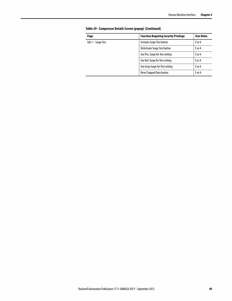
Table 29 - Compressor Details Screen (popup)
Page Function Requiring Security Privilege User Roles
Tab 1 – Compressor Head Ratio of Specific Heats value E or A
Polytropic Efficiency value E or A
Polytropic Exponent Type setting E or A
Max Polytropic Exponent Limit value E or A
Min Polytropic Exponent Limit value E or A
Table 28 - PID Loop Device Screen (popup) (Continued)
Page Function Requiring Security Privilege User Roles
Rockwell Automation Publication 1711-UM002A-EN-P - September 2012 47

Chapter 4 Human Machine Interface
Tab 2 - Base Conditions Orifice Base Pressure value E or A
Orifice Base Temperature value E or A
Orifice Maximum Flow value E or A
Compressor Base Pressure value E or A
Compressor Base Temperature value E or A
Gas Molecular Weight value E or A
Gas Compressibility E or A
Use IGV Position for Map setting E or A
IGV Minimum Position Limit value E or A
Tab 3 – Surge Map Surge Map – X-axis OP values E or A
Surge Map – Y-Axis Head values E or A
Surge Map – IGV Position values E or A
Tab 4 – OPTrack/Decoupling OP Track – Max Track Limit value M, E or A
OP Track – Track Margin value M, E or A
OP Track – Track Rate value M, E or A
Decoupling – Initiate Point 1 value M, E or A
Decoupling – Release Point 2 value M, E or A
Use Decoupling setting E or A
Tab 5 – ASC and CAP valves ASCV – Open Slew Rate value M, E or A
ASCV – Close Slew Rate value M, E or A
ASCV – Max CV Limit value M, E or A
ASCV – Min CV Limit value M, E or A
ASCV – CV NotRun/Unload/Trip value M, E or A
ASCV – Position Deviation DB value M, E or A
ASCV – Position Deviation Time value M, E or A
CapCV – Open Slew Rate value M, E or A
CapCV – Close Slew Rate value M, E or A
CapCV – Max CV Limit value M, E or A
CapCV – Min CV Limit value M, E or A
CapCV – CV NotRun/Unload/Trip value M, E or A
CapCV – Position Deviation DB value M, E or A
CapCV – Position Deviation Time value M, E or A
Tab 6 – Surge Configuration Multi-Surge Trip Quantity value E or A
Multi-Surge Trip Time value E or A
Rate-of-Change Low value M, E or A
Rate-of-Change Deadband value M, E or A
Rate-of-Change Time value M, E or A
Positional Surge Margin value M, E or A
Reset Surge Count button E or A
Table 29 - Compressor Details Screen (popup) (Continued)
Page Function Requiring Security Privilege User Roles
48 Rockwell Automation Publication 1711-UM002A-EN-P - September 2012
Human Machine Interface Chapter 4
Tab 7 – Surge Test Activate Surge Test button E or A
DeActivate Surge Test button E or A
Use Pos. Surge for Test setting E or A
Use RoC Surge for Test setting E or A
Use Incip Surge for Test setting E or A
Reset Trapped Data button E or A
Table 29 - Compressor Details Screen (popup) (Continued)
Page Function Requiring Security Privilege User Roles
Rockwell Automation Publication 1711-UM002A-EN-P - September 2012 49

Chapter 4 Human Machine Interface
Notes:
50 Rockwell Automation Publication 1711-UM002A-EN-P - September 2012

Chapter 5
SSCC Configuration
This section contains the steps required to configure the SSCC. The SSCC can be applied to a variety of control requirements including anti-surge control, capacity/performance control, additional protection/override controls, as well as unit interlocks and permissives.
Parameter Lists Because of the wide range of control capabilities, there is a large amount of configuration choices which can be made in order to meet the requirements of the application. Configuration choices have been organized into groups called “parameter lists.” Thus, the configurable parameters grouped together in a parameter list represent a device (for example, a transmitter), or a control function (for example, a PID loop) or a common theme (for example, the compressor surge map).
Each parameter list contains the parameter number, description, range, and initial value. A User-configured Value column is also provided in each table for recording purposes. To use this feature, print the lists and record any values changed during configuration in this column.
Table 30 identifies the parameter lists and provides a summary of the configuration parameters that make up the list.
Table 30 - Available Configuration Parameter Lists
Parameter List Name Summary of Parameters
01: AIN - Compressor Flow on page 53 Usage, engineering unit scaling, and alarm configuration.
02: AIN - Suction Pressure on page 54 Usage, engineering unit scaling, and alarm configuration.
03: AIN - Discharge Pressure on page 55 Usage, engineering unit scaling, and alarm configuration.
04: AIN - Auxiliary Control Signal on page 56 Usage, engineering unit scaling, and alarm configuration.
05: AIN - Suction Temperature on page 57 Usage, engineering unit scaling, and alarm configuration.
06: AIN - Discharge Temperature on page 58 Usage, engineering unit scaling, and alarm configuration.
07: AIN - Multi-use Signal A on page 59 Usage, engineering unit scaling, and alarm configuration.
08: AIN - Multi-use Signal B on page 60 Usage, engineering unit scaling, and alarm configuration.
09: Digital Input Channel Configuration on page 61 DI channel usage and signal state configuration.
10: Digital Output Channel Configuration on page 63 DO channel control state configuration.
11: Compressor Configuration Information on page 63 Base properties for the compressor map, flow measurement, gas properties, head calculation method, inlet guide vane usage.
Rockwell Automation Publication 1711-UM002A-EN-P - September 2012 51

Chapter 5 SSCC Configuration
Refer to the following sections for details on each of the parameter lists, and the configuration settings and options for the parameters that make up each list.
12: Surge Map Definition on page 65 Compressor surge map (10-segment lookup table) values (head vs. operating point, plus inlet guide vane positions if applicable).
13: Surge and Margin Configuration on page 66 Anti-surge control margin properties, surge detection properties, and operating point tracking properties.
14: Run and Load Configuration on page 68 Compressor run determination, and manual/auto load configuration.
15: Anti-Surge Control General Configuration on page 69 Anti-surge control and valve properties including control value limits, slew rates, position deviation alarming. Anti-surge PID loop min/max selection and tracking.
16: ASC Primary PID Loop on page 70 Configuration properties for the primary anti-surge PID loop. This loop is always configured to control the anti-surge valve.
17: ASC Primary PID Loop - Adaptive Integral on page 72 Adaptive integral tuning parameters for the primary anti-surge PID loop.
18: ASC Primary PID Loop - Adaptive Proportional on page 73
Adaptive proportional tuning parameters for the primary anti-surge PID loop.
19: ASC Secondary PID Loop on page 74 Configuration properties for the secondary anti-surge PID loop. This is the optional protection/override PID loop which may be used to control the anti-surge valve.
20: Capacity Control General Configuration on page 76 Capacity control and valve/device properties including control value limits, slew rates, position deviation alarming. Capacity PID loop min/max selection and tracking.
21: Capacity Primary PID Loop on page 78 Configuration properties for the primary capacity PID loop. When capacity control is required, this is the PID loop used to control the capacity valve/device.
22: Capacity Secondary PID Loop on page 80 Configuration properties for the secondary capacity PID loop. This is the optional protection/override PID loop which may be used to control the capacity valve/device.
23: Anti-Surge - Capacity Decoupling Configuration on page 82
Configures the use of decoupling between the anti-surge and capacity controls.
24: AINs - Substitute PV on page 83 Configure each analog input channel to allow/disallow the use of substitute PV.
25: DINs - Substitute PV on page 84 Configure each digital input channel to allow/disallow the use of substitute PV.
26: Reserved for Future Use on page 84 Intentionally omitted from the HMI, reserved for future use only.
27: Interlock Bypassable Configuration on page 85 Configure the bypass option for individual interlocks.
28: Permissive Bypassable Configuration on page 86 Configure the bypass option for individual permissives.
29: Modbus Serial Port Configuration on page 87 Configure, set and read the configuration for the Modbus serial port of the controller.
30: Application (HMI Configuration) on page 88 HMI application configuration properties (consult factory before making any changes).Configure whether bypasses are permitted for the unit.
Table 30 - Available Configuration Parameter Lists (Continued)
Parameter List Name Summary of Parameters
52 Rockwell Automation Publication 1711-UM002A-EN-P - September 2012

SSCC Configuration Chapter 5
01: AIN - Compressor Flow
List 01 defines the usage, engineering unit scaling and linearization, and alarm configuration for the analog input channel 0 for compressor flow. The compressor flow input is the primary input used to calculate the operating point (OP) value of the compressor.
The following table identifies the configuration parameters, range limits, and initial values.
Table 31 - Parameter List 01: AIN – Compressor Flow
No. Description Range Initial Value User-configured Value
01 Channel Usage Configuration. Choices:1 = Qs, suction flow2 = Qd, discharge flow, and no inter-stage or discharge coolers3 = Qdd, discharge flow downstream of any inter-stage or discharge coolers (requires suction and discharge temperatures to be configured)4 = Qalt, an alternate measurement signal is used instead of Flow (special case, requires special considerations to determine surge map)
1…4 1
02 Engineering Unit Scale Max Limit (EU).The scaled engineering unit value at 20 mA input.
-999999…999999 100
03 Engineering Unit Scale Min Limit (EU).The scaled engineering unit value at 4 mA input.
-999999…999999 0
04 Scaling Type. Choices:0 = Linear1 = Square-root extraction (applicable to flow signals)
0 or 1 1
05 Extrapolate Scaling, if input beyond normal limits.0 = No, clamp EU value at min and max limits1 = Yes, extrapolate EU value beyond limits
0 or 1 0
06 Absolute Adjustment, Engineering Units (applicable to pressure and temperature signals). 0…999999 0
07 Has Alarm High Level.0 = No, high level alarm not to be used1 = Yes, high level alarm to be used
0 or 1 0
08 Has Alarm Low Level.0 = No, low level alarm not to be used1 = Yes, low level alarm to be used
0 or 1 0
09 High Alarm Limit Value. Engineering Units. -999999…999999 100
10 Low Alarm Limit Value. Engineering Units. -999999…999999 0
11 Alarm Deadband. Engineering units. 0…999999 0
Rockwell Automation Publication 1711-UM002A-EN-P - September 2012 53

Chapter 5 SSCC Configuration
02: AIN - Suction Pressure
List 02 defines the usage, engineering unit scaling and linearization, and alarm configuration for the analog input channel 1 for suction pressure. The suction pressure input is used for the following purposes.
• A variable in calculating the compressor “head”
• As pressure compensation in the operating point calculation (when flow usage is Qs, Qd, or Qdd)
• As the process variable (PV) for the anti-surge secondary (override) PID loop, or capacity primary or capacity secondary PID loops (if selected)
The following table identifies the configuration parameters, range limits, and initial values.
Table 32 - Parameter List 02: AIN – Suction Pressure
No. Description Range Initial Value User-configured Value
01 Channel Usage Configuration. Choices:0 = Not configured 1 = Suction PressureUsage should always be configured = 1. In rare cases where the compressor has no suction pressure transmitter, configure = 1 and use substitute PV to set the value equal to the compressor base pressure.
0 or 1 1
02 Engineering Unit Scale Max Limit (EU).The scaled engineering unit value at 20 mA input.
-999999…999999 100
03 Engineering Unit Scale Min Limit (EU).The scaled engineering unit value at 4 mA input.
-999999…999999 0
04 Scaling Type. Choices:0 = Linear1 = Square-root extraction (applicable to flow signals)
0 or 1 0
05 Extrapolate Scaling, if input beyond normal limits.0 = No, clamp EU value at min and max limits1 = Yes, extrapolate EU value beyond limits
0 or 1 0
06 Absolute Adjustment. Engineering units.If transmitter is a gauge transmitter, enter the amount to convert to absolute pressure.If the transmitter is an absolute transmitter, enter 0.
0…999999 0
07 Has Alarm High Level.0 = No, high level alarm not to be used1 = Yes, high level alarm to be used
0 or 1 0
08 Has Alarm Low Level.0 = No, low level alarm not to be used1 = Yes, low level alarm to be used
0 or 1 0
09 High Alarm Limit Value. Engineering units. -999999…999999 100
10 Low Alarm Limit Value. Engineering units. -999999…999999 0
11 Alarm Deadband. Engineering units. 0…999999 0
54 Rockwell Automation Publication 1711-UM002A-EN-P - September 2012

SSCC Configuration Chapter 5
03: AIN - Discharge Pressure
List 03 defines the usage, engineering unit scaling and linearization, and alarm configuration for the analog input channel 2 for discharge pressure. The discharge pressure input is used for the following purposes.
• A variable in calculating the compressor “head”
• As pressure compensation in the operating point calculation (when flow usage is Qd or Qdd)
• As the process variable (PV) for the anti-surge secondary (override) PID loop, or capacity primary or capacity secondary PID loops (if selected)
The following table identifies the configuration parameters, range limits, and initial values.
Table 33 - Parameter List 03: AIN – Discharge Pressure
No. Description Range Initial Value User-configured Value
01 Channel Usage Configuration. Choices:0 = Not configured 1 = Discharge PressureUsage should always be configured = 1.
0 or 1 1
02 Engineering Unit Scale Max Limit (EU).The scaled engineering unit value at 20 mA input.
-999999…999999 100
03 Engineering Unit Scale Min Limit (EU).The scaled engineering unit value at 4 mA input.
-999999…999999 0
04 Scaling Type. Choices:0 = Linear1 = Square-root extraction (applicable to flow signals)
0 or 1 0
05 Extrapolate Scaling, if input beyond normal limits.0 = No, clamp EU value at min and max limits1 = Yes, extrapolate EU value beyond limits
0 or 1 0
06 Absolute Adjustment. Engineering units.If transmitter is a gauge transmitter, enter the amount to convert to absolute pressure.If the transmitter is an absolute transmitter, enter 0.
0…999999 0
07 Has Alarm High Level.0 = No, high level alarm not to be used1 = Yes, high level alarm to be used
0 or 1 0
08 Has Alarm Low Level.0 = No, low level alarm not to be used1 = Yes, low level alarm to be used
0 or 1 0
09 High Alarm Limit Value. Engineering units. -999999…999999 100
10 Low Alarm Limit Value. Engineering units. -999999…999999 0
11 Alarm Deadband. Engineering units. 0…999999 0
Rockwell Automation Publication 1711-UM002A-EN-P - September 2012 55

Chapter 5 SSCC Configuration
04: AIN - Auxiliary Control Signal
List 04 defines the usage, engineering unit scaling and linearization, and alarm configuration for the analog input channel 3 provided for an auxiliary control signal. The auxiliary input signal is used for the following purposes.
• As the process variable (PV) for the anti-surge secondary (override) PID loop, or capacity primary or capacity secondary PID loops (if selected)
The following table identifies the configuration parameters, range limits, and initial values.
Table 34 - Parameter List 04: AIN – Auxiliary Control Signal
No. Description Range Initial Value User-configured Value
01 Channel Usage Configuration. Choices:0 = Not configured 1 = Configured for useThe auxiliary control signal is optional.
0 or 1 0
02 Engineering Unit Scale Max Limit (EU).The scaled engineering unit value at 20 mA input.
-999999…999999 100
03 Engineering Unit Scale Min Limit (EU).The scaled engineering unit value at 4 mA input.
-999999…999999 0
04 Scaling Type. Choices:0 = Linear1 = Square-root extraction (applicable to flow signals)
0 or 1 0
05 Extrapolate Scaling, if input beyond normal limits.0 = No, clamp EU value at min and max limits1 = Yes, extrapolate EU value beyond limits
0 or 1 0
06 Absolute Adjustment. Engineering units.If transmitter is a gauge transmitter, enter the amount to convert to absolute value.If the transmitter is an absolute transmitter, enter 0.
0…999999 0
07 Has Alarm High Level.0 = No, high level alarm not to be used1 = Yes, high level alarm to be used
0 or 1 0
08 Has Alarm Low Level.0 = No, low level alarm not to be used1 = Yes, low level alarm to be used
0 or 1 0
09 High Alarm Limit Value. Engineering units. -999999…999999 100
10 Low Alarm Limit Value. Engineering units. -999999…999999 0
11 Alarm Deadband. Engineering units. 0…999999 0
56 Rockwell Automation Publication 1711-UM002A-EN-P - September 2012

SSCC Configuration Chapter 5
05: AIN - Suction Temperature
List 05 defines the usage, engineering unit scaling and linearization, and alarm configuration for the analog input channel 4 for suction temperature. The suction temperature input is used for the following purposes.
• A variable in calculating the compressor “head” (when variable polytropic exponent is configured)
• As temperature compensation in the operating point calculation (when flow usage is Qdd)
The following table identifies the configuration parameters, range limits, and initial values.
Table 35 - Parameter List 05: AIN - Suction Temperature
No. Description Range Initial Value User-configured Value
01 Channel Usage Configuration. Choices:0 = Not configured 1 = Suction temperature configured for useThe suction temperature configuration is required when the flow usage is configured as Qdd.
0 or 1 0
02 Engineering Unit Scale Max Limit (EU).The scaled engineering unit value at 20 mA input.
-999999…999999 100
03 Engineering Unit Scale Min Limit (EU).The scaled engineering unit value at 4 mA input.
-999999…999999 0
04 Scaling Type. Choices:0 = Linear1 = Square-root extraction (applicable to flow signals)
0 or 1 0
05 Extrapolate Scaling, if input beyond normal limits.0 = No, clamp EU value at min and max limits1 = Yes, extrapolate EU value beyond limits
0 or 1 0
06 Absolute Adjustment. Engineering units.For internal calculations, the temperature must be converted into absolute units. Enter the absolute adjustment value:For DegF transmitters: set to 460 to convert to DegRFor DegC transmitters: set to 273 to convert to DegKSuction and discharge transmitters must be in the same units.
0…999999 0
07 Has Alarm High Level.0 = No, high level alarm not to be used1 = Yes, high level alarm to be used
0 or 1 0
08 Has Alarm Low Level.0 = No, low level alarm not to be used1 = Yes, low level alarm to be used
0 or 1 0
09 High Alarm Limit Value. Engineering units. -999999…999999 100
10 Low Alarm Limit Value. Engineering units. -999999…999999 0
11 Alarm Deadband. Engineering units. 0…999999 0
Rockwell Automation Publication 1711-UM002A-EN-P - September 2012 57

Chapter 5 SSCC Configuration
06: AIN - Discharge Temperature
List 06 defines the usage, engineering unit scaling and linearization, and alarm configuration for the analog input channel 5 for discharge temperature. The discharge temperature input is used for the following purposes.
• A variable in calculating the compressor “head” (when variable polytropic exponent is configured)
• As temperature compensation in the operating point calculation (when flow usage is Qdd)
The following table identifies the configuration parameters, range limits, and initial values.
Table 36 - Parameter List 06: AIN – Discharge Temperature
No. Description Range Initial Value User-configured Value
01 Channel Usage Configuration. Choices:0 = Not configured 1 = Discharge temperature configured for useThe discharge temperature configuration is required when the flow usage is configured as Qdd.
0 or 1 0
02 Engineering Unit Scale Max Limit (EU).The scaled engineering unit value at 20 mA input.
-999999…999999 100
03 Engineering Unit Scale Min Limit (EU).The scaled engineering unit value at 4 mA input.
-999999…999999 0
04 Scaling Type. Choices:0 = Linear1 = Square-root extraction (applicable to flow signals)
0 or 1 0
05 Extrapolate Scaling, if input beyond normal limits.0 = No, clamp EU value at min and max limits1 = Yes, extrapolate EU value beyond limits
0 or 1 0
06 Absolute Adjustment. Engineering units.For internal calculations, the temperature must be converted into absolute units. Enter the absolute adjustment value:For DegF transmitters: set to 460 to convert to DegRFor DegC transmitters: set to 273 to convert to DegKSuction and discharge transmitters must be in the same units.
0…999999 0
07 Has Alarm High Level.0 = No, high level alarm not to be used1 = Yes, high level alarm to be used
0 or 1 0
08 Has Alarm Low Level.0 = No, low level alarm not to be used1 = Yes, low level alarm to be used
0 or 1 0
09 High Alarm Limit Value. Engineering units. -999999…999999 100
10 Low Alarm Limit Value. Engineering units. -999999…999999 0
11 Alarm Deadband. Engineering units. 0…999999 0
58 Rockwell Automation Publication 1711-UM002A-EN-P - September 2012

SSCC Configuration Chapter 5
07: AIN - Multi-use Signal A
List 07 defines the usage, engineering unit scaling and linearization, and alarm configuration for the analog input channel 6 for multi-use signal A. The multi-use signal input can be used for the following purposes.
• A valve position feedback transmitter, for either the anti-surge valve, or the capacity control valve/guide vanes.
• The incipient surge detection signal from the optional SurgeGard device.
The following table identifies the configuration parameters, range limits, and initial values.
Note: Multi-use signal A and multi-use signal B usage should not be configured for the same signal type.
Table 37 - Parameter List 07: AIN – Multi-use Signal A
No. Description Range Initial Value User-configured Value
01 Channel Usage Configuration. Choices:0 = Not configured 1 = PosA, anti-surge valve position transmitter2 = PosCap, capacity valve/guide vane position transmitter3 = SG, SurgeGard incipient surge detection signal.Note: When configured for SurgeGard incipient surge detection signal, the High Alarm is used as the signal threshold that triggers the incipient surge control value increment action (see parameter 09 in list 15: Anti-Surge Control General Configuration on page 69).
0…3 0
02 Engineering Unit Scale Max Limit (EU).The scaled engineering unit value at 20 mA input.
-999999…999999 100
03 Engineering Unit Scale Min Limit (EU).The scaled engineering unit value at 4 mA input.
-999999…999999 0
04 Scaling Type. Choices:0 = Linear1 = Square-root extraction (applicable to flow signals)
0 or 1 0
05 Extrapolate Scaling, if input beyond normal limits.0 = No, clamp EU value at min and max limits1 = Yes, extrapolate EU value beyond limits
0 or 1 0
06 Absolute Adjustment. Engineering units.Not applicable for this signal, set to 0.
0…999999 0
07 Has Alarm High Level.0 = No, high level alarm not to be used1 = Yes, high level alarm to be used
0 or 1 0
08 Has Alarm Low Level.0 = No, low level alarm not to be used1 = Yes, low level alarm to be used
0 or 1 0
09 High Alarm Limit Value. Engineering units. -999999…999999 100
10 Low Alarm Limit Value. Engineering units. -999999…999999 0
11 Alarm Deadband. Engineering units. 0…999999 0
Rockwell Automation Publication 1711-UM002A-EN-P - September 2012 59

Chapter 5 SSCC Configuration
08: AIN - Multi-use Signal B
List 08 defines the usage, engineering unit scaling and linearization, and alarm configuration for the analog input channel 7 for multi-use signal A. The multi-use signal input can be used for the following purposes.
• A valve position feedback transmitter, for either the anti-surge valve, or the capacity control valve/guide vanes.
• The incipient surge detection signal from the optional SurgeGard device.
The following table identifies the configuration parameters, range limits, and initial values.
Note: Multi-use signal A and multi-use signal B usage should not be configured for the same signal type.
Table 38 - Parameter List 08: AIN – Multi-use Signal B
No. Description Range Initial Value User-configured Value
01 Channel Usage Configuration. Choices:0 = Not configured 1 = PosA, anti-surge valve position transmitter2 = PosCap, capacity valve/guide vane position transmitter3 = SG, SurgeGard incipient surge detection signalNote: When configured for SurgeGard incipient surge detection signal, the High Alarm is used as the signal threshold that triggers the incipient surge control value increment action (see parameter 09 in list 15: Anti-Surge Control General Configuration on page 69).
0…3 0
02 Engineering Unit Scale Max Limit (EU).The scaled engineering unit value at 20 mA input.
-999999…999999 100
03 Engineering Unit Scale Min Limit (EU).The scaled engineering unit value at 4 mA input.
-999999…999999 0
04 Scaling Type. Choices:0 = Linear1 = Square-root extraction (applicable to flow signals)
0 or 1 0
05 Extrapolate Scaling, if input beyond normal limits.0 = No, clamp EU value at min and max limits1 = Yes, extrapolate EU value beyond limits
0 or 1 0
06 Absolute Adjustment. Engineering units.Not applicable for this signal, set to 0.
0…999999 0
07 Has Alarm High Level.0 = No, high level alarm not to be used1 = Yes, high level alarm to be used
0 or 1 0
08 Has Alarm Low Level.0 = No, low level alarm not to be used1 = Yes, low level alarm to be used
0 or 1 0
09 High Alarm Limit Value. Engineering units. -999999…999999 100
10 Low Alarm Limit Value. Engineering units. -999999…999999 0
11 Alarm Deadband. Engineering units. 0…999999 0
60 Rockwell Automation Publication 1711-UM002A-EN-P - September 2012

SSCC Configuration Chapter 5
09: Digital Input Channel Configuration
List 09 defines the usage and signal state for the all of the digital input channels. The following table identifies the configuration parameters, range limits, and initial values.
Table 39 - Parameter List 09: Digital Input Channel Configuration
No. Description Range Initial Value User-configured Value
01 Use Compressor Run Signal input (DI Channel 0).0 = No, do not use this signal1 = Yes, Use this signal for compressor run detection
0 or 1 0
02 Compressor Run State (DI Channel 0).0 = Compressor running state when input is Off1 = Compressor running state when input is On
0 or 1 1
03 Use Reset Push Button Signal Input (DI Channel 1).0 = No, do not use this signal1 = Yes, Use this signal for Reset push button
0 or 1 0
04 Reset Push Button State (DI Channel 1).0 = Trigger reset action when input is Off1 = Trigger reset action when input is On
0 or 1 1
05 Use Load Push Button Signal Input (DI Channel 2).0 = No, do not use this signal1 = Yes, use this signal for Load push button
0 or 1 0
06 Load Push Button State (DI Channel 2).0 = Trigger load request when input is Off1 = Trigger load request when input is On
0 or 1 1
07 Use Unload Push Button Signal Input (DI Channel 3).0 = No, do not use this signal1 = Yes, Use this signal for Unload push button
0 or 1 0
08 Unload Push Button State (DI Channel 3).0 = Trigger unload request when input is Off1 = Trigger unload request when input is On
0 or 1 1
09 Use External Ready-To-Start-1 Signal Input (DI Channel 8).0 = No, do not use this signal1 = Yes, use this signal for Ready-To-Start-1 condition
0 or 1 0
10 External Ready-To-Start-1 State (DI Channel 8).0 = Ready-To-Start state when input is Off1 = Ready-To-Start state when input is On
0 or 1 1
11 Use External Ready-To-Start-2 Signal Input (DI Channel 9).0 = No, do not use this signal1 = Yes, use this signal for Ready-To-Start-2 condition
0 or 1 0
12 External Ready-To-Start-2 State (DI Channel 9).0 = Ready-To-Start state when input is Off1 = Ready-To-Start state when input is On
0 or 1 1
13 Use External Ready-To-Start-3 Signal Input (DI Channel 10).0 = No, do not use this signal1 = Yes, use this signal for Ready-To-Start-3 condition
0 or 1 0
14 External Ready-To-Start-3 State (DI Channel 10).0 = Ready-To-Start state when input is Off1 = Ready-To-Start state when input is On
0 or 1 1
Rockwell Automation Publication 1711-UM002A-EN-P - September 2012 61

Chapter 5 SSCC Configuration
15 Use External Ready-To-Start-4 Signal Input (DI Channel 11).0 = No, do not use this signal1 = Yes, use this signal for Ready-To-Start-4 condition
0 or 1 0
16 External Ready-To-Start-4 State (DI Channel 11).0 = Ready-To-Start state when input is Off1 = Ready-To-Start state when input is On
0 or 1 1
17 Use External Compressor Trip-1 Signal Input (DI Channel 12).0 = No, do not use this signal1 = Yes, use this signal for compressor Trip-1 condition
0 or 1 0
18 External Compressor Trip-1 State (DI Channel 12).0 = Compressor Trip state when input is Off1 = Compressor Trip state when input is On
0 or 1 0
19 Use External Compressor Trip-2 Signal Input (DI Channel 13).0 = No, do not use this signal1 = Yes, use this signal for compressor Trip-2 condition
0 or 1 0
20 External Compressor Trip-2 State (DI Channel 13).0 = Compressor Trip state when input is Off1 = Compressor Trip state when input is On
0 or 1 0
21 Use External Compressor Trip-3 Signal Input (DI Channel 14).0 = No, do not use this signal1 = Yes, use this signal for compressor Trip-3 condition
0 or 1 0
22 External Compressor Trip-3 State (DI Channel 14).0 = Compressor Trip state when input is Off1 = Compressor Trip state when input is On
0 or 1 0
23 Use External Compressor Trip-4 Signal Input (DI Channel 15).0 = No, do not use this signal1 = Yes, use this signal for compressor Trip-4 condition
0 or 1 0
24 External Compressor Trip-4 State (DI Channel 15).0 = Compressor Trip state when input is Off1 = Compressor Trip state when input is On
0 or 1 0
Table 39 - Parameter List 09: Digital Input Channel Configuration (Continued)
No. Description Range Initial Value User-configured Value
62 Rockwell Automation Publication 1711-UM002A-EN-P - September 2012

SSCC Configuration Chapter 5
10: Digital Output Channel Configuration
List 10 defines the signal state for the all of the digital output channels. The following table identifies the configuration parameters, range limits, and initial values.
11: Compressor Configuration Information
List 11 defines general properties for the compressor configuration. These properties represent the following items.
• Base pressure and temperature of the manufacturer’s compressor map• Gas properties of the manufacturer’s compressor map• Base properties of the compressor Flow measurement• Head calculation type for surge map data (polytropic or pressure ratio)• Inlet guide vane usage and associated map technique.
The following table identifies the configuration parameters, range limits, and initial values.
Table 40 - Parameter List 10: Digital Output Channel Configuration
No. Description Range Initial Value User-configured Value
01 Compressor Trip Output (DO Channel 0).0 = Normally de-energized, energize for compressor Trip1 = Normally energized, de-Energize for compressor Trip
0 or 1 1
02 Compressor Run Output (DO Channel 1).0 = Normally de-energized, energize for compressor Run1 = Normally energized, de-energize for compressor Run
0 or 1 0
03 Ready-To-Start Output (DO Channel 2).0 = Normally de-energized, energize for Ready-To-Start1 = Normally energized, de-energize for Ready-To-Start
0 or 1 0
04 System Trouble Output (DO Channel 3).0 = Normally de-energized, energize for system trouble1 = Normally energized, de-energize for system trouble
0 or 1 0
05 Surge Alarm Output (DO Channel 4).0 = Normally de-energized, energize for surge alarm1 = Normally energized, de-energize for surge alarm
0 or 1 0
06 Compressor Load Output (DO Channel 5).0 = Normally de-energized, energize for compressor Load1 = Normally energized, de-energize for compressor Load
0 or 1 0
Rockwell Automation Publication 1711-UM002A-EN-P - September 2012 63

Chapter 5 SSCC Configuration
Table 41 - Parameter List 11: Compressor Configuration Information
No. Description Range Initial Value User-configured Value
01 Compressor Base Temperature, Tbc.Enter in absolute temperature units (i.e. Kelvin or Rankin), matching the absolute correction units of any temperature transmitters.
0…999999 0
02 Compressor Base Pressure, Pbc.Enter in absolute pressure units, matching the absolute correction units of the pressure transmitters.
0…999999 0
03 Design Gas Ratio of Specific Heats, k (Cp/Cv). 0…2 0
04 Compressor Polytropic Efficiency, Peff.Polytropic efficiency at surge point.
0…1 0
05 Compressor Flow Device (Orifice) Base Temperature, Tbo.Enter in absolute temperature units (i.e. Kelvin or Rankin), matching the absolute correction units of any temperature transmitters, and the compressor base temperature.
0…999999 0
06 Compressor Flow Device (Orifice) Base Pressure, Pbo.Enter in absolute pressure units, matching the absolute correction units of the pressure transmitters, and the compressor base pressure.
0…999999 0
07 Max Flow Range, used for surge map Flow normalization.From the Rockwell Automation compressor toolset surge map definition.
0…999999 0
08 Head Type, for surge map. Choices:0 = HpSim, simplified polytropic Head1 = Pratio, pressure ratio (Pd/Ps)
0 or 1 0
09 Polytropic Exponent Calculation Type. Choices:0 = Fixed/constant, calculated from k, and Peff1 = Variable, calculated from actual pressures/temperatures using log ratios
0 or 1 0
10 Variable Polytropic Exponent Max Limit.Used when polytropic exponent type set to “Variable.”Sets the max limit for the calculated value.
0…10 0
11 Variable Polytropic Exponent Min LimitUsed when polytropic exponent type set to “Variable.”Sets the min limit for the calculated value.
0 to 10 0
12 Adjust Surge Map Using Inlet Guide Vanes. Choices:0 = No, use the surge map without adjustment1 = Yes, use inlet guide vane adjustment technique
0 or 1 0
13 Inlet Guide Vane (IGV) Min Limit for Adjustment.Used when IGV adjustment technique is configured for use.Sets the min limit for the IGV adjustment.
0…100 0
14 Design Gas Molecular Weight, MW.From compressor map, for reference only, not used in calculations.
0…200 0
15 Design Gas Compressibility, Z.From compressor map, for reference only, not used in calculations.
0…2 0
64 Rockwell Automation Publication 1711-UM002A-EN-P - September 2012

SSCC Configuration Chapter 5
12: Surge Map Definition
List 12 defines the surge map for the compressor. The SSCC utilizes a ten-segment lookup table to represent the surge map plotting Head vs. Flow (normalized as %Q2). When the compressor includes inlet guide vanes (IGV), the IGV position is also configured for each point on the surge map.
The surge map values for Head and normalized Flow are typically generated using the Rockwell Automation compressor toolset. The toolset allows the user to enter values taken directly from the manufacturer’s compressor map, and generates the Head (HpSim or Pratio) and Flow (%Q2) values required by the anti-surge control algorithms in the SSCC.
The following table identifies the configuration parameters, range limits, and initial values.
Table 42 - Parameter List 12: Surge Map Definition
No. Description Range Initial Value User-configured Value
0102030405060708091011
X-axis Values (%Q2, 11 points), for compressor surge map.Values represent the Flow-squared, normalized over a Flow max range (referred to as %Q-squared, or %Q2).Values typically generated using the Rockwell Automation compressor toolset.Values must be ascending:
Pt-0 <= Pt-1, Pt-1 <= Pt-2,…Pt-8 <= Pt-9, Pt-9 < Pt-10When not all points are required, set each point in the list to 0.0, as required. For example, if only four points are defined, enter them at parameters 8…11 (%Q2 Pt-7…Pt-10), and prefill parameters 1…7 (%Q2 Pt-0…Pt-6) = 0.0.
0…100 0
1213141516171819202122
Y-axis Values (Head, 11 points), for compressor surge map.Values represent Head expressed in simplified polytropic Head, or pressure ratio (as identified in List 11, parameter 8).Values typically generated using the Rockwell Automation compressor toolset.Values must be ascending:
Pt-0 <= Pt-1, Pt-1 <= Pt-2,…Pt-8 <= Pt-9, Pt-9 < Pt-10When not all points are required, pre-fill the list as required. For example, if only four points are defined, enter them at parameters 19…22 (Head, Pt-7…Pt-10), and prefill parameters 12…18 = 0.0 (for HpSim) or = 1.0 (for Pratio).
0…100 0
2324252627282930313233
Inlet Guide Vane Values (IGV, 11 points), for compressor surge map. Applicable only for compressor with inlet guide vanes (IGV). Values represent IGV position expressed in %-open.Values typically generated using the Rockwell Automation compressor toolset.Values must be ascending:
Pt-0 <= Pt-1, Pt-1 <= Pt-2,…Pt-8 <= Pt-9, Pt-9 < Pt-10When not all points are required, pre-fill the list as required. For example, if only four IGV points are defined, enter them at parameters 30…33 (IGV, Pt-7…Pt-10), and prefill parameters 23…32 = 0.0 (IGV Pt-0…Pt-6).
0…100 0
Rockwell Automation Publication 1711-UM002A-EN-P - September 2012 65

Chapter 5 SSCC Configuration
13: Surge and Margin Configuration
List 13 defines the surge detection and control margin properties. These properties establish the following items.
• Control margin calculations which set the distance between the surge limit line (SLL) and the control limit line.
• Surge detection methods, which detect surge based on changes to the operating point, either positionally (it falls below the SLL by a defined amount) or rate-of-change (it decreases rapidly, exceeding a falling low threshold).
• Operating point tracking, which establishes the surge control line (SCL) used as the setpoint for the anti-surge primary PID loop.
The following table identifies the configuration parameters, range limits, and initial values.
Table 43 - Parameter List 13: Surge and Margin Configuration
No. Description Range Initial Value User-configured Value
01 Base Offset Margin, %.The offset margin is one form of margin used to establish the distance from the surge limit line (SLL) to the control limit line (CLL).The base offset margin represents the min offset margin that will be used.The offset margin in use can be incrementally adjusted manually by the operator, or automatically on surge detection.
0…100 10
02 Base Percent Margin, %.The percent margin is a second form of margin used to establish the distance from the SLL to the CLL.This margin contributes a percentage of the SLL value towards the total margin. Thus, the lower the SLL value, the smaller the percent margin contribution, and the higher the SLL value, the larger the percent margin contribution.Combining the percent margin with the offset margin provides great flexibility in total margin determination.The base percent margin represents the minimum percent margin that will be used.The percent margin in use can be incrementally adjusted manually by the operator, or automatically on surge detection.
0…100 20
03 Maximum Margin Limit, %.This limit is applied individually to the offset margin in use, the percent margin in Use, as well as the calculated total margin in use.
0…100 30
004 Margin Adjustment Amount, %.The margin in use can be incrementally adjusted by the operator or automatically when surge is detected. This parameter sets the amount of adjustment.
0…10 1
05 Margin Adjustment Type.When margin in use is incrementally adjusted, this parameter specifies what form of margin is adjusted. Choices:1 = Offset margin in use2 = Percent margin in use3 = Both offset and percent margin in use
1…3 1
06 Backup Margin, %.The backup margin determines the limit for manual control of the anti-surge primary PID loop. If the distance between the operating point (OP) and the surge limit line (SLL) is less than the backup margin, then the anti-surge primary PID loop mode is forced to automatic to prevent the operator from driving the compressor into surge.
0…100 3
66 Rockwell Automation Publication 1711-UM002A-EN-P - September 2012

SSCC Configuration Chapter 5
07 Backup and Surge Deadband, %.Sets the deadband used for the backup margin condition, and the positional surge alarm condition.
0…100 1
08 Surge Trip Quantity.Quantity of surges for the multiple surge trip interlock.
0…10 4
09 Surge Trip Time, seconds.The duration of time for the multiple surge trip interlock.If the quantity of surges (parameter 8) occur within this amount of time, the multiple surge trip interlock is generated, which triggers the compressor trip output.
0…600 30
10 Surge Detection – Rate of Change Low Threshold (-%/sec).Establishes the rate-of-change (RoC) low threshold for operating point which is reported as a surge.
-99999…0 -25
11 Surge Detection – Rate of Change Deadband (%/sec).A deadband used by the RoC calculation to clear the RoC surge condition.
099999 10
12 Surge Detection – Rate-of-Change Time, milliseconds.Parameters 10, 11, and, 12 are used together to specify a surge detection method for rate-of-change (RoC) on the operating point (OP). The RoC of the OP is calculated every scan of the controller (set to 20 msec). The RoC maintains up to 50 samples of RoC values spanning up to 1 second (50 * 20 msec = 1000 msec). The RoC function calculates the average RoC over the time defined by parameter 12 by averaging the relevant quantity of samples. When this calculated average RoC is lower than the low threshold value (parameter10) a surge detection based on RoC is determined. This condition remains until the average RoC is greater than the RoC low threshold plus RoC deadband (parameter 11).
0…1000 200
13 Surge Detection – Position Surge Margin, %.Positional surge is detected when the operating point falls below the surge limit line by this amount.
-100…0 -2
14 Operating Point Track Margin, %.OP tracking establishes the surge control line (SCL). As the OP increases and moves to the right of the control limit line, the SCL may track the OP by this track margin.
0…100 5
15 Operating Point Track Rate, %/sec.When the OP decreases back towards the CLL, this parameter determines the rate that the SCL is reduces back towards the CLL.
0…100 1
16 Operating Point Track Max SP Limit, %.This parameter sets the maximum limit for the SCL.For example, with OP track max limit set to 75%, and the OP track margin set to 5.0%, the SCL will track the OP by 5% up to an OP value of 80%. At this point the SCL is tracking the OP at 75%. If the OP increases beyond 80%, the SCL remains limited at 75%.
0…100 75
Table 43 - Parameter List 13: Surge and Margin Configuration (Continued)
No. Description Range Initial Value User-configured Value
Rockwell Automation Publication 1711-UM002A-EN-P - September 2012 67

Chapter 5 SSCC Configuration
14: Run and Load Configuration
List 14 defines the properties used for compressor running determination and for manual/automatic loading for the compressor. Compressor running determination is normally based on the digital input (DIN) for compressor running (when a DI channel is configured for use).
Compressor running determination can also optionally be base on the following conditions.
• A head threshold
• An auxiliary control signal (e.g. motor amps) threshold
• An on-delay timer preset and off-delay timer preset for confirmed run status
The following table identifies the configuration parameters, range limits, and initial values.
Table 44 - Parameter List 14: Run and Load Configuration
No. Description Range Initial Value User-configured Value
01 Automatically Load compressor on Run condition. Choices:0 = No1 = Yes
0 or 1 0
02 Use Auxiliary Control Signal for Run determination. Choices:0 = No1 = Yes
0 or 1 0
03 Auxiliary Control Signal Threshold for Running, EU.When parameter 2 is set to “Yes,” this parameter defines the threshold for the Run determination.Run condition if (AuxCntrlSig > Threshold)Example: For a motor driven compressor, the aux control signal analog input signal could be wired to a motor-amps transducer. If motor amps are greater than a set threshold, then the compressor is running.
-999999…999999 0
04 Use Head for Run determination. Choices:0 = No1 = Yes
0 or 1 0
05 Head Value Threshold for Running, EU.When parameter 4 is set to “Yes,” this parameter defines the threshold for the Run determination.Run condition if (Head > Threshold)
0…100 0
06 Confirmed Run Status On-delay Timer Preset, seconds.This value is the preset for the confirmed run status on-delay time. Until the compressor is confirmed running, loading is not permitted, and the anti-surge and capacity control devices are held at their override/unload/not running position.This on-delay timer applies to all options for Run condition, in other words, the Comp Run DI, AuxCntrlSig threshold, and Head threshold.
0…600 10
07 Confirmed Run Status Off-delay Timer Preset, seconds.This value is the preset for the confirmed run status off-delay time. Once confirmed run status is set, running condition(s) must clear for this off-delay time before the confirmed run status is cleared.
0…60 1
68 Rockwell Automation Publication 1711-UM002A-EN-P - September 2012

SSCC Configuration Chapter 5
15: Anti-Surge Control General Configuration
List 15 defines general properties for anti-surge control that are independent from the primary and secondary anti-surge PID loops. These general configuration properties are used for the following controls.
• Anti-surge valve control value limits
• Anti-surge valve slew rate limits
• Ant-surge valve position deviation alarming
• Anti-surge PID loop min/max selection
• Anti-surge PID loop tracking
The following table identifies the configuration parameters, range limits, and initial values.
Table 45 - Parameter List 15: Anti-Surge Control General Configuration
No. Description Range Initial Value User-configured Value
01 Anti-surge PID Loop Output Min/Max Select Type. Choices:0 = Minimum select1 = Maximum select
0 or 1 1
02 Not Running Control Value, % open.The anti-surge valve is set to this control value whenever the compressor is “Not Running” or “Unloaded.” This value overrides the PID output values calculated by the primary or secondary anti-surge PID loops.If this value exceeds the min or max CV limits expressed in parameters 7 and 8, the min/max limited value is used under the “Not Running” or “Unloaded” condition.
0…100 100
03 PID Track Margin, % Open.When both the primary and secondary anti-surge PID loops are configured, this value sets the tracking limit for the PID loop that is not producing the selected output. This keeps the non-controlling loop from winding up and moving away from the control value by more than a PID track margin.For example, if the PID track margin is set to 10%, the select type is set to “Maximum,” the compressor is Running and Loaded, the primary PID loop output is max selected and at 60%, and the secondary PID loop output is 55% and reducing. If the secondary loop output reduces below 50% (60% - 10%) the secondary output is limited (tracks) at 50%. If the primary loop output increases to 61%, the secondary loop tracking rises to 51% (61% - 10%).
0…100 5
04 Anti-surge Valve Location. Choices0 = Blow-Off valve1 = Recycle ValveThis setting is used to modify the representation of the anti-surge valve connections on the Process Overview page of the Operator screen.
0 or 1 1
05 Open Slew Rate, %/sec.Limits the opening rate of the control value.Normally, the anti-surge opening slew rate is set to allow fast opening.
0…999999 100
06 Close Slew Rate %/sec.Limits the closing rate of the control value.Normally, the anti-surge closing slew rate is set to close the valve slowly.
0…999999 2
07 Control Value Max Limit % Open.Sets the max limit for the control value for the valve.
0…100 100
Rockwell Automation Publication 1711-UM002A-EN-P - September 2012 69

Chapter 5 SSCC Configuration
16: ASC Primary PID Loop
List 16 defines the configuration settings for the anti-surge control primary PID loop. This PID loop is always configured and used for anti-surge control.
The process variable for this loop is always the calculated operating point (OP) value. The setpoint for this loop is always the surge control limit (SCL) value. Adaptive tuning is used for this loop (refer to List 17: ASC Primary PID Loop - Adaptive Integral on page 72 and List 18: ASC Primary PID Loop - Adaptive Proportional on page 73 for adaptive tuning configuration parameters).
The following table identifies the configuration parameters, range limits, and initial values. The initial values for these settings will usually not require changing.
08 Control Value Min Limit, % Open.Sets the min limit for the control value for the valve.
0…100 0
09 Incipient Surge Control Value Increment, % Open.On incipient surge detection, this control value is incremented by this amount. This increment is not subject to open slew rate limits.This increment serves to “bump” the anti-surge valve open more than the PID calculations are doing themselves when an incipient surge is detected.Note: This Incipient Surge Increment action requires that one of the multi-use analog input channels be configured for the SurgeGard signal input (see list 07: AIN - Multi-use Signal A on page 59 and list 08: AIN - Multi-use Signal B on page 60). Use the High Alarm of the configured channel for the incipient surge detection threshold.
0…100 10
10 Valve Fail Direction. Choices:0 = Closed (i.e. valve is air-to-open)1 = Open (i.e. valve is air-to-close)Typically, the anti-surge valve is air-to-close, and fails open.This setting is used to generate the analog output signal direction from the control value which is always expressed as % open.
1 1
11 Valve Position Deviation Alarm Deadband, %.When one of the multi-signal analog input channels is configured for anti-surge valve position feedback, the controller supports a position deviation alarm. This parameter sets the deadband limit for the alarm. When the difference between the control value and position feedback exceed this deadband, the deviation alarm timer is activated.
0…100 100
12 Valve Position Deviation Alarm Time, seconds.This parameter is the preset for the deviation alarm timer. If the position deviation remains active for this time, the position deviation alarm is generated.
0…60 60
Table 45 - Parameter List 15: Anti-Surge Control General Configuration (Continued)
No. Description Range Initial Value User-configured Value
70 Rockwell Automation Publication 1711-UM002A-EN-P - September 2012

SSCC Configuration Chapter 5
Table 46 - Parameter List 16: ASC Primary PID Loop
No. Description Range Initial Value User-configured Value
01 Setpoint Tracks PV in Manual Mode. Choices:0 = No1 = YesKeep this parameter set to 0. The setpoint is always set by the surge control line (SCL) value.
0 or 1 0
02 Setpoint Maximum Limit, Engineering Units (% Operating Point).Keep this parameter set to 100.The SCL calculation by operating point tracking has its own maximum limit for OP tracking. Use that parameter to limit the maximum SCL and thus the setpoint for this loop. See 13: Surge and Margin Configuration on page 66, parameter 16.
0…100 100
03 Setpoint Minimum Limit, Engineering Units (% Operating Point).Keep this parameter set to 0.The SCL calculation by OP tracking is always lower limited by the control limit line (CLL) value. There is no need to specify any other limitations on the setpoint for this loop.
0…100 0
04 Setpoint Increment Rate Limit, EU/sec.Keep this parameter set to a large value.The SCL is allowed to increase as fast as possible, so there is no need to limit this setpoint increasing rate.
0…999999 10000
05 Setpoint Decrement Rate Limit, EU/secKeep this parameter set to a large value.The SCL decreasing rate is set by the OP track rate (See 13: Surge and Margin Configuration on page 66, parameter 15). There is no need to further limit this setpoint decreasing rate.
0…999999 10000
06 PID Loop Deadband, Engineering Units (% Operating Point).Defines a deadband about the setpoint which treats error as 0, and thus no change to control value output.If used, normally kept small <= 1%
0…100 0
07 Proportional Action Calculation Type. Choices:0 = Calculate proportional based on change in PV1 = Calculate proportional based on errorKeep this parameter set to 1 for this loop.
0 or 1 1
08 Use Interactive Tuning. Choices:0 = No, Tuning parameters are non-interacting1 = Yes, Tuning parameters are interacting (traditional)Use for the ASC primary PID loop, which uses adaptive tuning. Keep this parameter set to 0.
0 or 1 0
09 Control Action. Choices:0 = Reverse1 = DirectUsed for the ASC primary PID loop. Keep this parameter set to 0 for “Reverse.”
0 or 1 0
10 PID Control Value (CV) Maximum Limit, % Open.Sets the maximum limit for the calculated PID control value output.Normally this parameter will be kept at 100.
0…100 100
11 PID Control Value (CV) Minimum Limit, % OpenSets the minimum limit for the calculated PID control value output.Normally this parameter will be kept at 0.
0…100 0
Rockwell Automation Publication 1711-UM002A-EN-P - September 2012 71

Chapter 5 SSCC Configuration
17: ASC Primary PID Loop - Adaptive Integral
List 17 defines the adaptive integral tuning properties used for the anti-surge control primary PID loop. The adaptive tuning parameters include the following feaetures.
• A base tuning value used when operating between breakpoints
• Tuning value minimum and maximum limits
• Breakpoints and slopes used to calculate the adaptive tuning value based on operating conditions
The following table identifies the configuration parameters, range limits, and initial values.
Table 47 - Parameter List 17: ASC Primary PID Loop – Adaptive Integral
No. Description Range Initial Value User-configured Value
01 Base Integral, Kbase, Repeats/minute.The base integral is the value used when operating within the breakpoints BP1 and BP2.
0…100 20
02 Maximum Limit for Adaptive Integral, Kmax, Repeats/minute.The calculated adaptive integral is limited to this maximum value.
0…100 100
03 Minimum Limit for Adaptive Integral, Kmin, Repeats/minute.The calculated adaptive integral is limited to this minimum value.
0…100 1
04 Breakpoint 1, BP1, %.The distance below (negative) the CLL where adaptive tuning calculation adjustment begins.
-20…0 -1
05 Breakpoint 2, BP2, %.The distance above (positive) the CLL where adaptive tuning calculation adjustment begins.
0…100 5
06 Slope 1, S1, Repeat/min / % .The slope used for adaptive tuning adjustment below breakpoint 1.
0…100 10
07 Slope 2, S2, Repeat/min / % .The slope used for adaptive tuning adjustment above breakpoint 2.
-100…100 2
72 Rockwell Automation Publication 1711-UM002A-EN-P - September 2012

SSCC Configuration Chapter 5
18: ASC Primary PID Loop - Adaptive Proportional
List 18 defines the adaptive proportional tuning properties used for the anti-surge control primary PID loop. The adaptive tuning parameters include the following features.
• A base tuning value used when operating between breakpoints
• Tuning value minimum and maximum limits.
• Breakpoints and slopes used to calculate the adaptive tuning value based on operating conditions.
The following table identifies the configuration parameters, range limits, and initial values.
Table 48 - Parameter List 18: ASC Primary PID Loop – Adaptive Proportional
No. Description Range Initial Value User-configured Value
01 Base Proportional, Kbase, Gain.The base proportional is the value used when operating within the breakpoints BP1 and BP2.
0…100 0.25
02 Maximum Limit for Adaptive Proportional, Kmax, Gain.The calculated adaptive proportional is limited to this maximum value.
0…100 10
03 Minimum Limit for Adaptive Proportional, Kmin, Gain.The calculated adaptive proportional is limited to this minimum value.
0…100 0.1
04 Breakpoint 1, BP1, %.The distance below (negative) the CLL where adaptive tuning calculation adjustment begins.
-20…0 -1
05 Breakpoint 2, BP2, %.The distance above (positive) the CLL where adaptive tuning calculation adjustment begins.
0…100 5
06 Slope 1, S1, Gain / %.The slope used for adaptive tuning adjustment below breakpoint 1.
0…100 2
07 Slope 2, S2, Gain / %.The slope used for adaptive tuning adjustment above breakpoint 2.
-100…100 -0.05
Rockwell Automation Publication 1711-UM002A-EN-P - September 2012 73

Chapter 5 SSCC Configuration
19: ASC Secondary PID Loop
List 19 defines the configuration settings for the anti-surge control secondary PID loop. This PID loop is optional, and must be configured for use using this parameter list. The configuration parameters for this loop include the following settings.
• Selection of a process variable (PV) signal for the loop
• Setpoint and associated limits, ramp rates and behaviors
• Control settings (direct/reverse action, CV limits, deadband)
• Loop tuning configuration and values
When this loop has been configured for use, the loop output is available to the min/max selection for the anti-surge control. The selector chooses the configured min/max output of primary and secondary ASC PID loop outputs.
The following table identifies the configuration parameters, range limits, and initial values.
Table 49 - Parameter List 19: ASC Secondary PID Loop
No. Description Range Initial Value User-configured Value
01 Process Variable Selection. Choices:0 = Not configured 1 = Q, Compressor Flow (AIN Channel 0)2 = Ps, Suction Pressure (AIN Channel 1)3 = Pd, Discharge Pressure (AIN Channel 2)4 = Aux, Auxiliary Control Signal (AIN Channel 3)The scaled engineering unit value is used for the PV of the PID loop, and the engineering unit range of the analog input channel is used for the PID loop PV engineering units.
0…4 0
02 Setpoint (EU).The setpoint for the PID loop. This value can be set here or using the PID loop faceplate. It is included here to allow it to be saved to the non-volatile memory of the HMI with the other parameters.
-999999…999999 0
03 Setpoint Tracks PV when Loop is in Manual. Choices:0 = No, Setpoint remains at its last value1 = Yes, Setpoint tracks the PV value when loop is in manual
0 or 1 0
04 Setpoint Maximum Limit (EU).Sets the maximum limit for the loop setpoint.
-999999…999999 0
05 Setpoint Minimum Limit (EU).Sets the minimum limit for the loop setpoint.
-999999…999999 0
06 Setpoint Increase Limit (EU/sec).Sets the increase ramp rate for the setpoint, in engineering units per second. For example, if set to 0.1, and the SP is changed from 70 to 80 psi, the SP in use will ramp from 70 to 80 at 0.1 psi-per-second. After 100 seconds, the SP will reach the value of 80 psi.
0…999999 10
07 Setpoint Decrease Limit (EU/sec).Sets the decrease ramp rate for the setpoint, in engineering units per second. For example, if set to 2 and the SP is changed from 300 to 280 Amps, the SP in use will ramp from 300 down to 280 at 2 Amps-per-second. After 10 seconds, the SP will reach the value of 280.
0…999999 10
74 Rockwell Automation Publication 1711-UM002A-EN-P - September 2012

SSCC Configuration Chapter 5
08 Proportional Tuning value (Gain).Tuning value for the proportional action of the PID loop, in units of gain. Gain represents the percent control value per percent-error. For example, to create a 2% change of output for each %-error, set the gain to 2. This representation is the reciprocal of proportional band.
0…100 1
09 Proportional Action based on PV or Error. Choices:0 = PV, Proportional action is based on changes in the process variable.1 = Error, Proportional action is based on errorWhen based on error, the proportional action responds to changes in setpoint. When based on PV, the proportional action responds to changes in PV only, and is not affected by setpoint changes.
0 or 1 1
10 Integral Tuning value (Repeats/minute) 0…100 2
11 Derivative Tuning value (seconds) 0…100 0
12 Interactive Tuning. Choices:0 = Non-Interactive. The proportional gain value does not interact with the integral or derivative contributions.1 = Interactive. The proportional gain is used to calculate the integral and derivative contributions. The setting of 1, “Interactive,” represents the traditional form of PID tuning behavior. In other words, increasing the gain also increases the integral and derivative contributions.The setting of 0, “Non-Interactive,” calculates the integral and derivative contributions independent of the proportional gain. The integral and derivative are calculated as if they have an effective gain of 1.
0 or 1 1
13 PID Loop Control Action (a.k.a. Direction). Choices:0 = Reverse Acting1 = Direct ActingThis parameter determines the direction the output moves in consequence to the direction the PV moves:Direct - An increasing PV will cause the output to increaseReverse - A increasing PV will cause the output to decrease
0 or 1 1
14 PID Control Value (CV) Maximum Limit (% Open).The maximum limit imposed on the control value (output) calculated by the PID loop. Normally set to 100% open, but can be reduced if desired.
0…100 100
15 PID Control Value (CV) Minimum Limit (% Open).The minimum limit imposed on the control value (output) calculated by the PID loop. Normally set to 0% open, but can be increased if desired.
0…100 0
16 PID Deadband (EU).A deadband in PV engineering units above and below the loop setpoint. When the PV is within the deadband, the output of the PID loop is held at its present value and not updated.
0…999999 0
Table 49 - Parameter List 19: ASC Secondary PID Loop (Continued)
No. Description Range Initial Value User-configured Value
Rockwell Automation Publication 1711-UM002A-EN-P - September 2012 75

Chapter 5 SSCC Configuration
20: Capacity Control General Configuration
List 20 defines general properties for capacity control that are independent from the primary and secondary capacity PID loops. These general configuration properties are used to define the following settings.
• Capacity device location/representation on Process Overview screen
• Capacity device control value limits
• Capacity device slew rate limits
• Capacity device position deviation alarming
• Capacity PID loop min/max selection
• Capacity PID loop tracking
The following table identifies the configuration parameters, range limits, and initial values.
Table 50 - Parameter List 20: Capacity Control General Configuration
No. Description Range Initial Value User-configured Value
01 Capacity PID Loop Output Min/Max Select Type. Choices:0 = Minimum select1 = Maximum select
0 or 1 0
02 Not Running Control Value, % Open.The capacity device is set to this control value whenever the compressor is “Not Running” or “Unloaded.” This value overrides the PID output values calculated by the primary or secondary capacity PID loops.If this value exceeds the min or max CV limits expressed in parameters 7 and 8, the min/max limited value is used under the “Not Running” or “Unloaded” condition.
0…100 0
03 PID Track Margin, % Open.When both the primary and secondary capacity PID loops are configured, this value sets the tracking limit for the PID loop that is not producing the selected output. This keeps the non-controlling loop from winding up and moving away from the control value by more than a PID track margin.For example, PID track margin set to 8%, Select Type is set to minimum, compressor running and loaded, primary PID loop output is min selected and at 35%, secondary PID loop output is 40% and increasing. If the secondary loop output increases above 43% (35% + 8%) the secondary output is limited (tracks) at 43%. If the primary loop output decreases to 32%, the secondary loop tracking reduces to 40% (32% + 8%).
0…100 5
04 Capacity Device Type and Location. Choices:0 = Capacity control not required, show no device1 = Suction valve throttling used for capacity control2 = Inlet guide vane used for capacity control3 = Discharge valve throttling used for capacity control4 = Variable speed used for capacity controlThis setting is used to modify the location and representation of the capacity device on the Process Overview page of the Operator screen.
0…4 0
05 Open Slew Rate, %/sec.Limits the opening rate of the control value.Normally, the capacity control opening slew rate is set for slow to moderate opening rate.
0 …999999 10
76 Rockwell Automation Publication 1711-UM002A-EN-P - September 2012

SSCC Configuration Chapter 5
06 Close Slew Rate %/sec.Limits the closing rate of the control value.Normally, the capacity control closing slew rate is set for slow to moderate closing rate.
0 …999999 10
07 Control Value Maximum Limit, % Open.Sets the maximum limit for the control value for the device.
0…100 100
08 Control Value Minimum Limit, % Open.Sets the minimum limit for the control value for the device.
0…100 0
09 Valve Fail Direction. Choices:0 = Closed (i.e. Valve is Air-to-Open)1 = Open (i.e. Valve is Air-to-Close)Typically, the device is Air-to-Open, and fails closed.This setting is used to generate the analog output signal direction from the control value which is always expressed as % open.
0 or 1 0
10 Device Position Deviation Alarm Deadband, %.When one of the multi-signal analog input channels is configured for capacity device position feedback, the controller supports a position deviation alarm. This parameter sets the deadband limit for the alarm. When the difference between the control value and position feedback exceed this deadband, the deviation alarm timer is activated.
0…100 100
11 Device Position Deviation Alarm Time, seconds.This parameter is the preset for the deviation alarm timer. If the position deviation remains active for this time, the position deviation alarm is generated.
0…60 60
Table 50 - Parameter List 20: Capacity Control General Configuration (Continued)
No. Description Range Initial Value User-configured Value
Rockwell Automation Publication 1711-UM002A-EN-P - September 2012 77

Chapter 5 SSCC Configuration
21: Capacity Primary PID Loop
List 21 defines the configuration settings for the capacity control primary PID loop. This PID loop is optional, and must be configured for use using this parameter list. The configuration parameters for this loop include the following settings.
• Selection of a process variable (PV) signal for the loop
• Setpoint and associated limits, ramp rates and behaviors
• Control settings (direct/reverse action, CV limits, deadband)
• Loop tuning configuration and values
When this loop has been configured for use, the loop output is available to the min/max selection for the capacity control. The selector chooses the configured min/max output of primary and secondary capacity PID loop outputs.
The following table identifies the configuration parameters, range limits, and initial values.
Table 51 - Parameter List 21: Capacity Primary PID Loop
No. Description Range Initial Value User-configured Value
01 Process Variable Selection. Choices:0 = Not configured 1 = Q, Compressor Flow (AIN Channel 0)2 = Ps, Suction Pressure (AIN Channel 1)3 = Pd, Discharge Pressure (AIN Channel 2)4 = Aux, Auxiliary Control Signal (AIN Channel 3)The scaled engineering unit value is used for the PV of the PID loop, and the engineering unit range of the analog input channel is used for the PID loop PV engineering units.
0…4 0
02 Setpoint (EU).The setpoint for the PID loop. This value can be set here or using the PID loop faceplate. It is included here to allow it to be saved to the non-volatile memory of the HMI with the other parameters.
-999999…999999 0
03 Setpoint Tracks PV when Loop is in Manual. Choices:0 = No, Setpoint remains at its last value1 = Yes, Setpoint tracks the PV value when loop is in manual
0 or 1 0
04 Setpoint Maximum Limit (EU).Sets the maximum limit for the loop setpoint.
-999999…999999 0
05 Setpoint Minimum Limit (EU).Sets the minimum limit for the loop setpoint.
-999999…999999 0
06 Setpoint Increase Limit (EU/sec).Sets the increase ramp rate for the setpoint, in engineering units per second. For example, if set to 0.1, and the SP is changed from 70 to 80 psi, the SP in use will ramp from 70 to 80 at 0.1 psi-per-second. After 100 seconds, the SP will reach the value of 80 psi.
0…999999 10
07 Setpoint Decrease Limit (EU/sec).Sets the decrease ramp rate for the setpoint, in engineering units per second. For example, if set to 2 and the SP is changed from 300 to 280 Amps, the SP in use will ramp from 300 down to 280 at 2 Amps-per-second. After 10 seconds, the SP will reach the value of 280.
0…999999 10
78 Rockwell Automation Publication 1711-UM002A-EN-P - September 2012

SSCC Configuration Chapter 5
08 Proportional Tuning value (Gain).Tuning value for the proportional action of the PID loop, in units of gain. Gain represents the percent control value per percent-error. For example, to create a 2% change of output for each %-error, set the gain to 2. This representation is the reciprocal of proportional band.
0…100 1
09 Proportional Action based on PV or Error. Choices:0 = PV, Proportional action is based on changes in the process variable.1 = Error, Proportional action is based on errorWhen based on error, the proportional action responds to changes in setpoint. When based on PV, the proportional action responds to changes in PV only, and is not affected by setpoint changes.
0 or 1 1
10 Integral Tuning value (Repeats/minute) 0…100 2
11 Derivative Tuning value (seconds) 0…100 0
12 Interactive Tuning. Choices:0 = Non-Interactive. The proportional gain value does not interact with the integral or derivative contributions.1 = Interactive. The proportional gain is used to calculate the integral and derivative contributions. The setting of 1, “Interactive,” represents the traditional form of PID tuning behavior,. In other words, increasing the gain also increases the integral and derivative contributions.The setting of 0, “Non-Interactive,” calculates the integral and derivative contributions independent of the proportional gain. The integral and derivative are calculated as if they have an effective gain of 1.
0 or 1 1
13 PID Loop Control Action (a.k.a. Direction). Choices:0 = Reverse Acting1 = Direct ActingThis parameter determines the direction the output moves in consequence to the direction the PV moves:Direct - An increasing PV will cause the output to increaseReverse - A increasing PV will cause the output to decrease
0 or 1 1
14 PID Control Value (CV) Maximum Limit (% Open).The maximum limit imposed on the control value (output) calculated by the PID loop. Normally set to 100% open, but can be reduced if desired.
0…100 100
15 PID Control Value (CV) Minimum Limit (% Open).The minimum limit imposed on the control value (output) calculated by the PID loop. Normally set to 0% open, but can be increased if desired.
0…100 0
16 PID Deadband (EU).A deadband in PV engineering units above and below the loop setpoint. When the PV is within the deadband, the output of the PID loop is held at its present value and not updated.
0…999999 0
Table 51 - Parameter List 21: Capacity Primary PID Loop (Continued)
No. Description Range Initial Value User-configured Value
Rockwell Automation Publication 1711-UM002A-EN-P - September 2012 79

Chapter 5 SSCC Configuration
22: Capacity Secondary PID Loop
List 19 defines the configuration settings for the capacity control secondary PID loop. This PID loop is optional, and must be configured for use using this parameter list. The configuration parameters for this loop include the following settings.
• Selection of a process variable (PV) signal for the loop
• Setpoint and associated limits, ramp rates and behaviors
• Control settings (direct/reverse action, CV limits, deadband)
• Loop tuning configuration and values
When this loop has been configured for use, the loop output is available to the min/max selection for the capacity control. The selector chooses the configured min/max output of primary and secondary capacity PID loop outputs.
The following table identifies the configuration parameters, range limits, and initial values.
Table 52 - Parameter List 22: Capacity Secondary PID Loop
No. Description Range Initial Value User-configured Value
01 Process Variable Selection. Choices:0 = Not configured 1 = Q, Compressor Flow (AIN Channel 0)2 = Ps, Suction Pressure (AIN Channel 1)3 = Pd, Discharge Pressure (AIN Channel 2)4 = Aux, Auxiliary Control Signal (AIN Channel 3)The scaled engineering unit value is used for the PV of the PID loop, and the engineering unit range of the analog input channel is used for the PID loop PV engineering units.
0…4 0
02 Setpoint (EU).The setpoint for the PID loop. This value can be set here or using the PID loop faceplate. It is included here to allow it to be saved to the non-volatile memory of the HMI with the other parameters.
-999999…999999 0
03 Setpoint Tracks PV when Loop is in Manual. Choices:0 = No, Setpoint remains at its last value1 = Yes, Setpoint tracks the PV value when loop is in manual
0 or 1 0
04 Setpoint Maximum Limit (EU).Sets the maximum limit for the loop setpoint.
-999999…999999 0
05 Setpoint Minimum Limit (EU).Sets the minimum limit for the loop setpoint.
-999999…999999 0
06 Setpoint Increase Limit (EU/sec).Sets the increase ramp rate for the setpoint, in engineering units per second. For example, if set to 0.1, and the SP is changed from 70 to 80 psi, the SP in use will ramp from 70 to 80 at 0.1 psi-per-second. After 100 seconds, the SP will reach the value of 80 psi.
0…999999 10
07 Setpoint Decrease Limit (EU/sec).Sets the decrease ramp rate for the setpoint, in engineering units per second. For example, if set to 2 and the SP is changed from 300 to 280 Amps, the SP in use will ramp from 300 down to 280 at 2 Amps-per-second. After 10 seconds, the SP will reach the value of 280.
0…999999 10
80 Rockwell Automation Publication 1711-UM002A-EN-P - September 2012
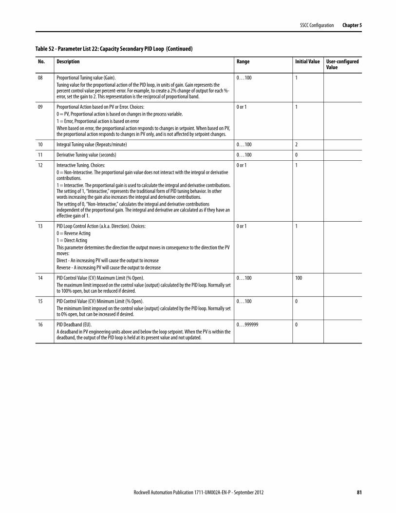
SSCC Configuration Chapter 5
08 Proportional Tuning value (Gain).Tuning value for the proportional action of the PID loop, in units of gain. Gain represents the percent control value per percent-error. For example, to create a 2% change of output for each %-error, set the gain to 2. This representation is the reciprocal of proportional band.
0…100 1
09 Proportional Action based on PV or Error. Choices:0 = PV, Proportional action is based on changes in the process variable.1 = Error, Proportional action is based on errorWhen based on error, the proportional action responds to changes in setpoint. When based on PV, the proportional action responds to changes in PV only, and is not affected by setpoint changes.
0 or 1 1
10 Integral Tuning value (Repeats/minute) 0…100 2
11 Derivative Tuning value (seconds) 0…100 0
12 Interactive Tuning. Choices:0 = Non-Interactive. The proportional gain value does not interact with the integral or derivative contributions.1 = Interactive. The proportional gain is used to calculate the integral and derivative contributions. The setting of 1, “Interactive,” represents the traditional form of PID tuning behavior. In other words increasing the gain also increases the integral and derivative contributions.The setting of 0, “Non-Interactive,” calculates the integral and derivative contributions independent of the proportional gain. The integral and derivative are calculated as if they have an effective gain of 1.
0 or 1 1
13 PID Loop Control Action (a.k.a. Direction). Choices:0 = Reverse Acting1 = Direct ActingThis parameter determines the direction the output moves in consequence to the direction the PV moves:Direct - An increasing PV will cause the output to increaseReverse - A increasing PV will cause the output to decrease
0 or 1 1
14 PID Control Value (CV) Maximum Limit (% Open).The maximum limit imposed on the control value (output) calculated by the PID loop. Normally set to 100% open, but can be reduced if desired.
0…100 100
15 PID Control Value (CV) Minimum Limit (% Open).The minimum limit imposed on the control value (output) calculated by the PID loop. Normally set to 0% open, but can be increased if desired.
0…100 0
16 PID Deadband (EU).A deadband in PV engineering units above and below the loop setpoint. When the PV is within the deadband, the output of the PID loop is held at its present value and not updated.
0…999999 0
Table 52 - Parameter List 22: Capacity Secondary PID Loop (Continued)
No. Description Range Initial Value User-configured Value
Rockwell Automation Publication 1711-UM002A-EN-P - September 2012 81

Chapter 5 SSCC Configuration
23: Anti-Surge - Capacity Decoupling Configuration
List 23 defines the configuration settings used for decoupling the anti-surge and capacity controls. The following decoupling features are available.
• Useful when anti-surge control and capacity control are configured in the SSCC. If capacity control is not configured, these settings can be ignored.
• Management of the anti-surge and capacity controls so they do not “fight” each other at operating points near the control limit line.
• At operating points between the specified initiate and release points, the capacity control action is held, so the capacity controller does not drive the compressor to surge.
• This decoupling method allows the anti-surge controller to stabilize flow first, and then release the capacity control for further action when safe to do so.
The following table identifies the configuration parameters, range limits, and initial values.
Table 53 - Parameter List 23: Anti-Surge – Capacity Decoupling Configuration
No. Description Range Initial Value User-configured Value
01 Use Decoupling. Choices:0 = No, do not use decoupling methods.1 = Yes, use the decoupling methods
0 or 1 0
02 Decoupling Initiate Point, DP1.This value defines the distance below the control limit line where decoupling action is Initiated. When the operating point moves below the control limit line by this distance, the capacity control output will be held.The value of DP1 should be further from 0 than DP2.In other words, DP1 < DP2 < 0.0
-100…0 -3
03 Decoupling Release Point, DP2.This value defines the distance below the control limit line where decoupling action is released. When the operating point moves within this distance of the control limit line, the decoupling action is released, and the capacity control output is free to move normally.The value of DP2 should be closer to 0 than DP1.In other words, DP1 < DP2 < 0.0
-100…0 -1
82 Rockwell Automation Publication 1711-UM002A-EN-P - September 2012

SSCC Configuration Chapter 5
24: AINs - Substitute PV
List 24 defines whether to allow or dis-allow the use of substitute PV for each analog input channel. Substitute PV mode allows the user to override the actual measured and scaled analog input value with a substitute process value entered by the user.
The configuration setting for use of substitute PV mode is configured as one of the following values.
0 = Allow Substitute PV mode to be used
1 = Dis-Allow Substitute PV mode
The following table identifies the configuration parameters, range limits, and initial values.
Table 54 - Parameter List 24: AINs – Substitute PV
No. Description Range Initial Value User-configured Value
01 Compressor Flow, Q (AIN channel 0) 0 or 1 0
02 Suction Pressure, Ps (AIN channel 1) 0 or 1 0
03 Discharge Pressure, Pd (AIN channel 2) 0 or 1 0
04 Auxiliary Control Signal, AuxCntrlSig (AIN channel 3) 0 or 1 0
05 Suction Temperature, Ts, (AIN channel 4) 0 or 1 0
06 Discharge Temperature, Td (AIN channel 5) 0 or 1 0
07 Multi-Use Signal A, (AIN channel 6) 0 or 1 0
08 Multi-Use Signal B, (AIN channel 7) 0 or 1 0
Rockwell Automation Publication 1711-UM002A-EN-P - September 2012 83
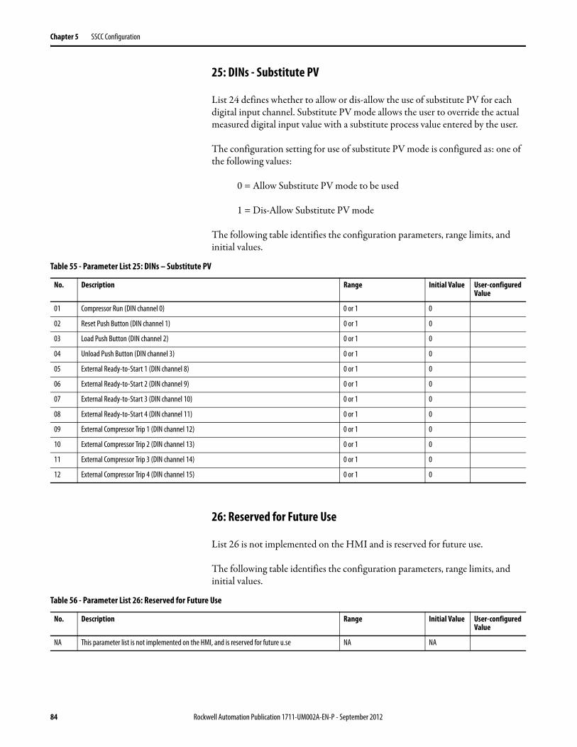
Chapter 5 SSCC Configuration
25: DINs - Substitute PV
List 24 defines whether to allow or dis-allow the use of substitute PV for each digital input channel. Substitute PV mode allows the user to override the actual measured digital input value with a substitute process value entered by the user.
The configuration setting for use of substitute PV mode is configured as: one of the following values:
0 = Allow Substitute PV mode to be used
1 = Dis-Allow Substitute PV mode
The following table identifies the configuration parameters, range limits, and initial values.
26: Reserved for Future Use
List 26 is not implemented on the HMI and is reserved for future use.
The following table identifies the configuration parameters, range limits, and initial values.
Table 55 - Parameter List 25: DINs – Substitute PV
No. Description Range Initial Value User-configured Value
01 Compressor Run (DIN channel 0) 0 or 1 0
02 Reset Push Button (DIN channel 1) 0 or 1 0
03 Load Push Button (DIN channel 2) 0 or 1 0
04 Unload Push Button (DIN channel 3) 0 or 1 0
05 External Ready-to-Start 1 (DIN channel 8) 0 or 1 0
06 External Ready-to-Start 2 (DIN channel 9) 0 or 1 0
07 External Ready-to-Start 3 (DIN channel 10) 0 or 1 0
08 External Ready-to-Start 4 (DIN channel 11) 0 or 1 0
09 External Compressor Trip 1 (DIN channel 12) 0 or 1 0
10 External Compressor Trip 2 (DIN channel 13) 0 or 1 0
11 External Compressor Trip 3 (DIN channel 14) 0 or 1 0
12 External Compressor Trip 4 (DIN channel 15) 0 or 1 0
Table 56 - Parameter List 26: Reserved for Future Use
No. Description Range Initial Value User-configured Value
NA This parameter list is not implemented on the HMI, and is reserved for future u.se NA NA
84 Rockwell Automation Publication 1711-UM002A-EN-P - September 2012

SSCC Configuration Chapter 5
27: Interlock Bypassable Configuration
List 27 contains the bypassable configuration for each of the interlocks for the compressor. When an interlock is configured as bypassable and bypasses are enabled, the interlock is bypassed and will not initiate the compressor trip.
Normally, the Interlock Configuration pop-up screen is used to set the interlock bypassable configuration. This parameter list is intended to allow this bypassable configuration to be saved to the non-volatile file memory of the HMI.
For each interlock, the bypassable configuration choice is 0 or 1.
0 = Not Bypassable
1 = Bypassable.
The following table identifies the configuration parameters, range limits, and initial values.
Table 57 - Parameter List 27: Interlock Bypassable Configuration
No. Description Range Initial Value User-configured Value
01 Multiple Surge Trip. 0 or 1 0
02 Operating Point Fault. 0 or 1 0
030405060708
Spare Interlocks. Choices:These six Interlock positions are not presently used in the SSCC application.
0 or 1 0
09 External Compressor Trip 1. 0 or 1 0
10 External Compressor Trip 2. 0 or 1 0
11 External Compressor Trip 3. 0 or 1 0
12 External Compressor Trip 4. 0 or 1 0
13141516
Spare Interlocks.These four Interlock positions are not presently used in the SSCC application.
0 or 1 0
Rockwell Automation Publication 1711-UM002A-EN-P - September 2012 85

Chapter 5 SSCC Configuration
28: Permissive Bypassable Configuration
List 27 contains the bypassable configuration for each of the permissives for the compressor. When a permissive is configured as bypassable and bypasses are enabled, the permissive is bypassed and will not affect the ready-to-start condition.
Normally, the Permissive Configuration pop-up screen is used to set the permissive bypassable configuration. This parameter list is intended to allow this Bypassable configuration to be saved to the non-volatile file memory of the HMI.
For each permissive, the bypassable configuration choice is 0 or 1:.
0 = Not Bypassable
1 = Bypassable.
The following table identifies the configuration parameters, range limits, and initial values.
Table 58 - Parameter List 28: Permissive Bypassable Configuration
No. Description Range Initial Value User-configured Value
01 Control Loops Ready. 0 or 1 0
02 Anti-Surge Valve Ready. 0 or 1 0
03 Capacity Valve/Inlet Guide Vane Ready. 0 or 1 0
04 Spare Permissive.These four Interlock positions are not presently used in the SSCC application.
0 or 1 0
05 Digital Inputs OK. 0 or 1 0
06 Analog Inputs OK. 0 or 1 0
07 Digital Outputs OK. 0 or 1 0
08 Analog Outputs OK. 0 or 1 0
09 External Ready-to-Start 1. 0 or 1 0
10 External Ready-to-Start 2. 0 or 1 0
11 External Ready-to-Start 3. 0 or 1 0
12 External Ready-to-Start 4. 0 or 1 0
13141516
Spare Permissives.These four permissive positions are not presently used in the SSCC application.
0 or 1 0
86 Rockwell Automation Publication 1711-UM002A-EN-P - September 2012

SSCC Configuration Chapter 5
29: Modbus Serial Port Configuration
List 29 defines the settings used for the Modbus serial port configuration. These parameters are used for the following settings.
• Set the slave ID and register scaling configuration
• Set the serial port baud rate and parity
• Read back the serial port baud rate and parity
The following table identifies the configuration parameters, range limits, and initial values.
Table 59 - Parameter List 29: Modbus Serial Port Configuration
No. Description Range Initial Value User-configured Value
01 Slave ID.The slave ID number identifies the controller number on a Modbus multi-drop serial link. Each controller on the multi-drop link has a unique slave ID.
1…254 1
02 Register Scaling Range.The internal engineering unit values in the controller are scaled to this integer range for sending over the Modbus protocol. Refer to Modbus Holding Registers on page 160 for details on the engineering unit ranges for Modbus variables.
1000…32767 32767
03 Baud Rate Configuration.Enter the desired baud rate for the Modbus serial port. Use parameter 7 of this list to trigger setting the port to this baud rate.
110, 300, 600, 1200, 2400, 4800, 9600, 19200, or 38400
19200
04 Parity Configuration.Enter the code to the right for the desired parity for the Modbus serial port. Use parameter 7 of this list to trigger setting the port to this parity.
0 = No Parity1 = Odd Parity2 = Even Parity
05 Baud Rate Readback.Leave the value of this parameter set to 0 (read only parameter).The CURR column reads back the actual baud rate in use on the controller.
110, 300, 600, 1200, 2400, 4800, 9600, 19200, or 38400
0
06 Parity Readback.Leave the value of this parameter set to 0 (read only parameter).The CURR column reads back the actual parity in use on the controller.
0 = No Parity1 = Odd Parity2 = Even Parity
0
07 Set Port Configuration.Set this value to 1 to trigger setting the serial port. Note: The controller always clears this value after setting the port, so the CURR column will always read back a 0 value.
0 or 1 0
Rockwell Automation Publication 1711-UM002A-EN-P - September 2012 87

Chapter 5 SSCC Configuration
30: Application (HMI Configuration)
List 30 defines key properties for the HMI application. These parameters are used for the following settings.
• The maximum number of pages to support on various HMI screens
• To permit or deny the use of interlock/permissive bypasses for the system
The following table identifies the configuration parameters, range limits, and initial values.
Table 60 - Parameter List 30: Application (HMI-related Configuration)
No. Description Range Initial Value User-configured Value
01 Maximum Operator ScreensSets the number of pages for the Operator screen.DO NOT CHANGE UNLESS ADVISED BY FACTORY.
0…8 6
02 Maximum Maintenance ScreensSets the number of pages for the Maintenance screen.DO NOT CHANGE UNLESS ADVISED BY FACTORY.
0…8 3
03 Maximum Warning ScreensSets the number of pages for the Warnings screen.DO NOT CHANGE UNLESS ADVISED BY FACTORY.
0…8 2
04 Maximum Interlocks ScreensSets the number of pages for the Interlocks screen.DO NOT CHANGE UNLESS ADVISED BY FACTORY.
0…8 2
05 Maximum Permissives ScreensSets the number of pages for the Permissives screen.DO NOT CHANGE UNLESS ADVISED BY FACTORY.
0…8 2
06 Maximum Help ScreensSets the number of pages for the Operator screen.DO NOT CHANGE UNLESS ADVISED BY FACTORY.
0…8 8
07 Maximum Status ScreensSets the number of pages for the Hardware Status screen.DO NOT CHANGE UNLESS ADVISED BY FACTORY.
0…8 3
08 Maximum IO CardsSets the number of IO modules presented in the IO module selector Hardware Status screen.DO NOT CHANGE UNLESS ADVISED BY FACTORY.
0…8 4
09 Bypass Enable. Choices:0 = Disable1 = EnableThis parameter is presented in the list, so that the current status of bypass enable/disable can be saved to the non-volatile file memory for archive.To enable and disable the bypasses, parameter 10 must be set to 1, and then use the Enable and Disable buttons on the Maintenance screen.
0 or 1 0
10 Has Bypass. Choices:0 = No, Hide the Bypass Enable/Disable buttons on the HMI1 = Yes, Present Bypass Enable/Disable buttons on the Maintenance screen of the HMIIf you want to configure and allow bypassing of interlocks and permissives on the HMI, then this parameter must be set to 1.
0 or 1 0
88 Rockwell Automation Publication 1711-UM002A-EN-P - September 2012
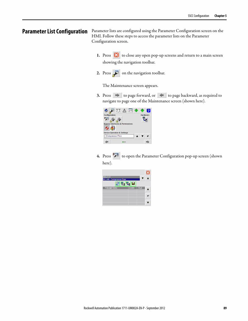
SSCC Configuration Chapter 5
Parameter List Configuration Parameter lists are configured using the Parameter Configuration screen on the HMI. Follow these steps to access the parameter lists on the Parameter Configuration screen.
1. Press to close any open pop-up screens and return to a main screen showing the navigation toolbar.
2. Press on the navigation toolbar.
The Maintenance screen appears.
3. Press to page forward, or to page backward, as required to navigate to page one of the Maintenance screen (shown here).
4. Press to open the Parameter Configuration pop-up screen (shown here).
Rockwell Automation Publication 1711-UM002A-EN-P - September 2012 89

Chapter 5 SSCC Configuration
Parameter Configuration Screen Overview
Figure 9 - Parameter Configuration Screen Components
Table 61 - Parameter Configuration Screen
Display Features (see Figure 9 for the location of these features):• Parameter list selector• Parameter list action buttons• Parameter details table• Parameter list action status (For example: Restore successful)Operational Features: • Press to the right of the Select field to choose a parameter list.
• Press to update the parameter details table - security privilege required (O, S, M, E, or A).
• Press to upload values from the controller and store them in the HMI file memory – security privilege required (E, or A).
• Press to download values from HMI file memory to the controller – security privilege required (E, or A).
• Press to save parameter value changes entered from the HMI to the HMI file memory – security privilege required (E, or A).
• Press or to the right of the parameter details table to choose a parameter.
• Press to the right of the parameter details table to edit the value for a selected parameter – security privilege required (E, or A). This opens the on-screen keypad for data entry.
Parameter List Selector
Parameter List Action Status
Close Button
List Selector Buttons
Scroll Up Button
Scroll Down Button
Edit Parameter Button
Parameter Details Table
90 Rockwell Automation Publication 1711-UM002A-EN-P - September 2012

SSCC Configuration Chapter 5
Parameter List Actions
The functions performed when using the parameter list action buttons are illustrated in Figure 10 and explained in detail in Table 62.
Figure 10 - Parameter List Action Details
Controller
HMINon-Volatile File Memory
Save
RestoreRestore
Upload
Download
Edit Parameter
Select List
Table 62 - Parameter List Actions Details
Button Action Security Operation Performed on the Selected Parameter
Restore O, S, M, E, or A Updates the Parameter Details table screen values:• Parameter names are read from the HMI file memory.• CURR value is read from the controller (read once, not continuous).• FILE value is read from the HMI file memory.
Upload E or A Reads values from the controller and stores them in the HMI file memory.• Clicking Upload does not update screen values.• After an upload, click Restore to view uploaded values on the screen.
Rockwell Automation Publication 1711-UM002A-EN-P - September 2012 91

Chapter 5 SSCC Configuration
When working with the parameter lists, you will typically complete a sequence of actions to accomplish the desired task. Use the following table to identify the task you want to complete and the recommended sequence of actions.
Download E or A Writes values from the HMI file memory to the controller.• Clicking the Download button does not write values from the screen to the controller and does not read values from the
controller (doesn’t update CURR column).• If you have modified values on the screen using Edit Parameter, then use Save before a download.• After a download use Restore to update CURR values from the controller.
Save E or A Saves all the screen values for the current parameter list to the HMI file memory. This function is normally used after making changes using Edit Parameter.• Does not save CURR values (from the controller) to the HMI file memory.• If you want to save controller values to the HMI file memory, use Upload.
Edit Parameter E or A Modifies the value presented on screen in the FILE column.• Does not change the value in the Controller.• Does not change the value in the HMI file memory.• After making changes using Edit Parameter, use Save to write the changed parameter values to the HMI file memory.
Table 62 - Parameter List Actions Details (Continued)
Button Action Security Operation Performed on the Selected Parameter
What Task Do You Want to Accomplish? Recommended Action Sequence
I want to view parameter configuration settings. 1. Select the desired parameter list.2. Click Restore to update the parameter table.3. Scroll as required to view parameter values.
I want to configure parameters for a new system. For each parameter list:1. Select the desired parameter list.2. Click Restore to update the parameter table on the screen.3. For each parameter in the list, click Edit Parameter to set the desired value.4. Click Save to save the configuration to the HMI file memory.5. Click Download to download the configuration to the controller.6. Click Restore to confirm the controller values.
I want to modify settings currently in use in the present controller.
Is your compressor running?• Yes: You cannot use the Parameter Configuration screen to make changes. Instead, you can use the device
faceplates on the HMI to change many configuration parameters.• No: Perform the following steps:
1. Select a parameter list.2. Click Restore to update the parameter table.3. Review the table to determine if the parameter you want to change in this list. If so continue, if not
return to step 1.4. Click Upload to read the controller values to the HMI file memory.5. Click Restore to update the parameter table (FILE column is updated from the Upload).6. Scroll to the parameter(s) you want to change, enter the desired value, and click Edit Parameter.7. Click Save to save the changes to the HMI file memory.8. Click Download to download the configuration to the controller.9. Click Restore to confirm the controller parameter values.
92 Rockwell Automation Publication 1711-UM002A-EN-P - September 2012

SSCC Configuration Chapter 5
Interlock and Permissive Customization
The SSCC system has pre-allocated input signals for use as interlocks and permissives for the compressor. These signals appear in the Interlocks and Permissive screens with initial names which may be customized. Interlock Configuration and Permissive Configuration screens allow for customizing these signals.
Follow these steps to navigate to the Maintenance screen, and open the Interlocks Configuration or Permissives Configuration screen.
1. Press to close any open pop-up screens and return to a main screen showing the navigation toolbar.
2. Press on the navigation toolbar.
The Maintenance screen appears.
I have changed settings in the controller using device faceplates on the HMI. Now I want to save the controller values to the HMI file memory.
Is your compressor running?• Yes: Wait until the compressor stops.• No: Complete the following steps:
For each parameter list:1. Select the desired parameter list.2. Click Upload to upload the controller values to the HMI file memory.3. Optional: Click Restore to update the parameter table values on the HMI screen. You can verify that
the CURR and FILE values now match.
I have replaced my controller, and it is loaded with the default SSCC Logix application and settings.
All my configured settings are saved in the HMI file memory.
I want to apply all my settings in the HMI to the controller.
If you have replaced the controller, you may need to re-activate the HMI. Refer to Activate the HMI on page 25.
If your HMI is successfully activated, follow these steps for each parameter list:1. Select the desired parameter list.2. Click Restore to display the contents of the list on the HMI screen.3. Review the list, checking that the FILE column has the intended values.4. Click Download to download the values to the controller.5. Click Restore to refresh the list on the screen.6. Review and confirm that the CURR values (from the controller) now match the FILE values (from the HMI file
memory).
All my settings are saved in the HMI file memory. I want to make an archive copy to a compact flash memory card.
In order to make an archive copy to a compact flash memory card, the normal HMI color graphics must be shut down to allow access the PanelView Plus file utilities. During this time, the HMI will be unavailable for compressor operation.
Follow these steps to shut down the HMI graphics – security privilege will be required.1. Navigate to page 1 of the Maintenance screen.
2. Press to display the Hardware Status screen.
3. Scroll to page 3 f the Hardware Status screen for PanelView maintenance.
4. Press to shutdown the HMI graphics.
Consult the PanelView Plus user manual for details on accessing the file utilities to copy the HMI application file to your compact flash card.
What Task Do You Want to Accomplish? Recommended Action Sequence
Rockwell Automation Publication 1711-UM002A-EN-P - September 2012 93
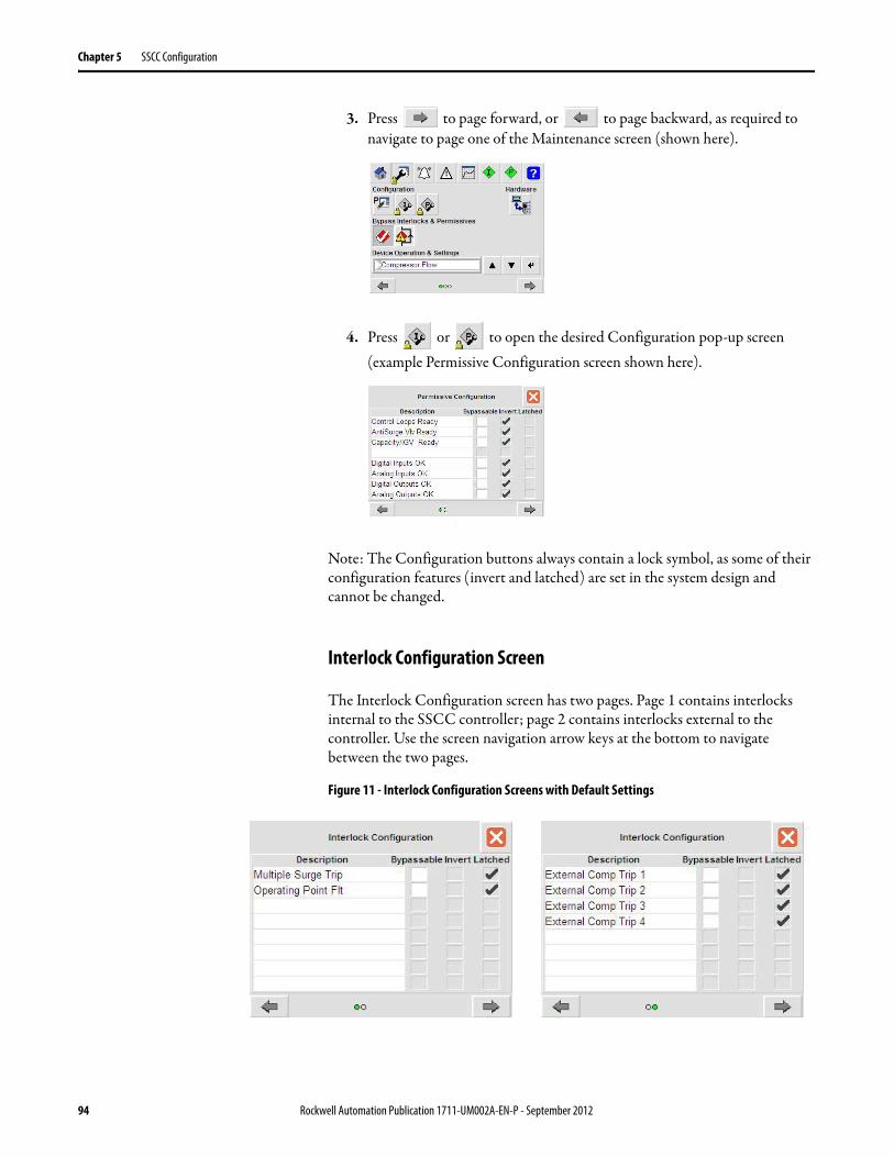
Chapter 5 SSCC Configuration
3. Press to page forward, or to page backward, as required to navigate to page one of the Maintenance screen (shown here).
4. Press or to open the desired Configuration pop-up screen (example Permissive Configuration screen shown here).
Note: The Configuration buttons always contain a lock symbol, as some of their configuration features (invert and latched) are set in the system design and cannot be changed.
Interlock Configuration Screen
The Interlock Configuration screen has two pages. Page 1 contains interlocks internal to the SSCC controller; page 2 contains interlocks external to the controller. Use the screen navigation arrow keys at the bottom to navigate between the two pages.
Figure 11 - Interlock Configuration Screens with Default Settings
94 Rockwell Automation Publication 1711-UM002A-EN-P - September 2012

SSCC Configuration Chapter 5
Customizing Interlocks
From the configuration screen, you can edit the interlock description. These represent string tags in the HMI (not the controller). These tags are retentive and saved in the HMI memory.
You are encouraged to customize the external interlock descriptions on page 2, to provide a more functional description. For example, you may connect a lube oil low pressure switch interlock, and therefore change the associated interlock description (e.g. “Low Lube Oil Press”). Editing the description requires security privileges (Engineer or Administrator). The description string tag limit is 20 characters.
Configuring Interlock Bypasses
Each interlock has a configuration option for “Bypassable.”The bypassable setting on this screen is the same as that configured in parameter List 27: Interlock Bypassable Configuration. Changing the bypassable setting requires security privileges (Engineer or Administrator).
An interlock is bypassed when:
1. The interlock is configured as “Bypassable,” and
2. Bypass is enabled on the Maintenance screen.
Permissive Configuration Screen
The Permissive Configuration screen has two pages. Page 1 contains permissives internal to the SSCC controller; page 2 contains permissives external to the controller. Use the screen navigation arrow keys at the bottom to navigate between the two pages.
Figure 12 - Persmissive Configuration Screens with Default Settings
Rockwell Automation Publication 1711-UM002A-EN-P - September 2012 95

Chapter 5 SSCC Configuration
Customizing Permissives
From the configuration screen, you may edit the permissive descriptions. These represent string Tags in the HMI (not the controller). These tags are retentive and saved in the HMI memory.
You are encouraged to customize the external permissive descriptions on page 2, to provide a more functional description. For example, you may connect a Lube Oil Auxiliary Pump Running permissive, and therefore change the associated permissive description (e.g. “Aux Lube Pump Run”). Editing the description requires security privileges (Engineer or Administrator). The description string tag limit is 20 characters.
Configuring Permissive Bypasses
Each permissive has a configuration option for “Bypassable.” The bypassable setting on this screen is the same as that configured in parameter list 28: Permissives Bypassable Configuration. Changing the bypassable setting requires security privileges (Engineer or Administrator).
A permissive is bypassed when:
1. The permissive is configured as “Bypassable,” and
2. Bypass is enabled on the Maintenance screen.
96 Rockwell Automation Publication 1711-UM002A-EN-P - September 2012

Chapter 6
SSCC Operation
This section provides details for the main Operation screens and guides you through the process of putting the SSCC in operation.
Operation Screen Details The main Operator screen has many visualization features that are based on choices made during configuration. This section provides details about these features.
Compressor Overview
The Compressor Overview is page 2 of the Operator screen. This screen provides a process diagram overview of the compressor and the configured instrumentation. Key features for anti-surge control are represented in the following illustration.
Figure 13 - Compressor Overview Page
Suction Transmitters• Pressure, Ps• Temperature, Ts• Flow, Qs(based on configuration)
Load / Unload Buttons
Anti-surge ControlDistance Between OP and CLL• Dist < 0.0 ASC Valve Opening• Dist ~ 0.0 ASC on Control Limit Line• Dist > 0.0 ASC Valve Closing
Anti-surge Control Valve• Recycle• Blow-off(based on configuration)
CV: Control ValvePos: Position Feedback (if configured)
Discharge Transmitters• Pressure, Pd• Temperature, Td• Flow, Qd, Qdd, Qalt(based on configuration)
Unit Status Indications
Optional Signals• Auxiliary Control PV• Incipient Surge Signal(based on configuration)
Rockwell Automation Publication 1711-UM002A-EN-P - September 2012 97

Chapter 6 SSCC Operation
The suction and discharge transmitters presented on the screen are based on the individual analog input channel configuration options. The units displayed for each transmitter (default “EU” shown) follow the unit string customization available on the analog input device faceplates.
The algorithm for anti-surge control calculates the operating point (OP). The instrumentation requirements are based on the type of flow measurement configured. These requirements are reflected in the following table.
Unit Status Indicators
The unit status indicators along the right side of the page reflect key operational controls/indications and correspond to the unit’s digital outputs. The indications presented on the screen are detailed in Table 63.
Flow Configuration Suction Transmitters Discharge Transmitters
Pressure, Ps Temperature, Ts Pressure, Pd Temperature, Td
Flow in Suction Required Optional Required Optional
Flow in Discharge,no coolers
Required Optional Required Optional
Flow in Discharge, downstream of coolers
Required Required Required Required
Alternate measurement Required Optional Required Optional
Table 63 - Unit Status Indicator Descriptions
Status Digital Output Status Indicator and Description
Ready Ready to Start, DO channel 3 Not Ready-to-Start, check permissives
Ready-to-Start, all permissives OK
Trip Comp Trip Interlock, DO channel 0 Not Tripped, all interlocks OK
Compressor Trip, check interlocks
Surge Surge Alarm, DO channel 1 Normal, no surge alarm
Surge alarm activated
Run Compressor Running, DO channel 4 Not Running, no Run condition detected
Confirmed Run determination
Load Compressor Loaded, DO channel 5 Unloaded, valves at override CV value
Loaded, valves released for control
Trouble System Trouble Alarm, DO channel 2 Normal
System trouble, hardware or device fault
98 Rockwell Automation Publication 1711-UM002A-EN-P - September 2012

SSCC Operation Chapter 6
Load / Unload Control Buttons
The Load and Unload buttons provide both control and indication of the control mode for the compressor. When unloaded, the SSCC drives the control valves to their configured override position. When loaded, the SSCC is allowed to control the valves based on the configured PID regulatory controls. The load/unload modes and indications are detailed in Table 64.
Capacity Control Visualization
When capacity control is configured, the capacity control type is visualized on the Compressor Overview page. The various capacity configuration options and visualization arrangements are detailed in the following illustrations.
Figure 14 - Capacity Control Type: Suction Throttling Example
Figure 15 - Capacity Control Type: Inlet Guide Vanes Example
Table 64 - Load / Unload Control Button Descriptions and Operations
Buttons Indication Description Button Operation Available
Unload mode – Valve control set to override CV value
None, security privilege required (O, S, M or E).
Load mode – Valve control released for regulatory control
None, security privilege required (O, S, M or E).
Unload mode – Valve control set to override CV value
Press to switch to Load mode.
Load mode – Valve control released for regulatory control
Press to switch to Unload mode.
CV: Control Valve, % OpenPos: Position Fdbk (if configured)
CV: Control Valve, % OpenPos: Position Fdbk (if configured)
Rockwell Automation Publication 1711-UM002A-EN-P - September 2012 99

Chapter 6 SSCC Operation
Figure 16 - Capacity Control Type: Discharge Throttling Example
Figure 17 - Capacity Control Type: Speed Setpoint to Speed Controller Example
CV: Control Valve, % OpenPos: Position Fdbk (if configured)
CV: Speed Setpoint, where:0% = Minimum Governor100% = Maximum Governor
100 Rockwell Automation Publication 1711-UM002A-EN-P - September 2012

SSCC Operation Chapter 6
Compressor Map
The Compressor Map is page 3 of the Operator screen. It provides a dynamic X-Y plot for the compressor map, key anti-surge calculated values (head, OP, SLL, CLL, SCL, and margin) and summary status for the anti-surge and capacity control signals. Key features of the Compressor Map page are represented in the following illustration.
Figure 18 - Compressor Map Page Example
Anti-surge Control Summary
Capacity Control Summary
Anti-surge Controls
Capacity Controls
CV to Anti-surge Valve
CV to Capacity Valve/Device
Secondary PID (Control vs. Tracking)PID Loop Output Control Value
Primary PID (Control vs. Tracking)PID Loop Output Control Value
(visible when loop(s) are configured)
Secondary PID (Control vs. Tracking)PID Loop Output Control Value
Primary PID (Control vs. Tracking)PID Loop Output Control Value
(visible when loop(s) are configured)
Dynamic Compressor MapY-Axis: Compressor HeadX-Axis: Normalized Flow, %(Q/QMAX)2
SLL: Surge Limit Line (red)CLL: Control Limit Line (green)SCL: Surge Control Line (blue)OP: Operating Point (yellow point)
Anti-Surge ControlDistance between OP and CLLDist < 0.0 ASC Valve OpeningDist ~ 0.0 ASC on Control Limit LineDist > 0.0 ASC Valve Closing
Rockwell Automation Publication 1711-UM002A-EN-P - September 2012 101

Chapter 6 SSCC Operation
Dynamic Compressor Map
The dynamic compressor map provides real-time presentation of the surge limit line, control limit line, surge control limit line (OP tracking), and the live operating point. This visualization provides a clear view of where the compressor is operating relative to surge and control limits, and how much margin is in use.
Further details of the compressor map are shown in the following illustration.
Figure 19 - Dynamic Compressor Map Example
Y-Axis: Compressor HeadScale is configured automatically based on values for Surge Line.
X-Axis: Normalized FlowScale is fixed at 0...100%(Q/QMAX)2
Margin
Surge Limit Line (SLL)Red line, 10-segment, plotted from the configured Surge Line values.
Control Limit Line (CLL)Green line, shaped the same as the SLL and shifted to the right by the Total Margin in use.
Compressor RunningAnti-surge control along the control line limit
Operating Point (OP)Yellow point, plotted at:X = OP valueY = Head value
Head
OP
Head
Compressor RunningAnti-surge valve closed,OP tracking safely to the right of the control limit line.
Surge Control Line (SCL)Blue line, shaped the same as the SLL, tracks the OP by the OP track margin.
SLL value
CLL value
SCL value
OP valueOP Track Margin
102 Rockwell Automation Publication 1711-UM002A-EN-P - September 2012

SSCC Operation Chapter 6
Margin Control
For the primary anti-surge PID, the setpoint is dynamic based on operating conditions and is automatically generated by the functional components of the algorithm. The operator does not directly enter the setpoint. However, the operator can influence the setpoint through adjustment of the margin. Margin adjustments are managed on the Margin Control page four of the Operator screen.
Key features of the Margin Control page are represented in the following illustration.
Figure 20 - Compressor Map Page Example Base Margins• The minimum limit for
the In Use values
Maximum Margin• Maximum limit for In
Use, and Total Margin
In Use Margins• Values in use, after
increment/decrement
Total Margin Results• Contributions for offset
and percent
Margin Increment / Decrement buttons• Adjusts the In Use values
Adjustment amount forincrement/decrement
Adjustment type determines which margin component(s) to adjust: 1 = Offset Margin only 2 = Percent Margin only 3 = Both Offset and Percent Margin
Offset Margin Only Percent Margin OnlySame margin for all operating conditions.
Margin varies:0 at minimum conditions.Increases with SLL.
Offset and Percent MarginTotal Margin varies:Offset value at minimum conditions. Increases with SLL as operating conditions increase.
Surge Limit LineControl Limit Line
Surge Limit LineControl Limit Line
Surge Limit LineControl Limit Line
=+
Rockwell Automation Publication 1711-UM002A-EN-P - September 2012 103

Chapter 6 SSCC Operation
Margin Configuration
The Margin Control page provides access to certain margin configuration properties from the configuration parameter list 13: Surge and Margin Configuration. A cross reference between the operator page and the parameter list is included here.
Margin Increment / Decrement
The anti-surge algorithm automatically increments the margin “in use” values whenever a surge is detected. The margin “in use” values may also be manually adjusted using and on the screen – security privilege required (O, S. M, E, or A). The adjustment amount and type are applied to these increments and decrements. The margins cannot be decremented less than the configured base margins, and cannot be incremented larger than the maximum margin limit.
Anti-Surge Control PID Loops Overview
Anti-surge control is provided through a primary PID loop configured to control the operating point relative to the surge control line. In addition, a secondary PID loop can be optionally configured, often based on suction pressure or discharge pressure.
Page 5 of the Operator screen provides an overview of these two anti-surge control PID loops.
Figure 21 - Operator Screen Page 5 Example
Screen Configuration Item Security Parameter List Cross ReferenceList 13: Surge and Margin Configuration
Offset Margin M, E or A 01: Base Offset Margin (%)
Percent Margin M, E or A 02: Base Percent Margin (%)
Maximum Margin M, E or A 03: Max Margin Limit (%)
Adjust Amount M, E or A 04: Margin Adj Amount (%)
Adjust Type M, E or A 05: Adj (1=Ofst, 2=Pct, 3=Both)
Primary Loop Pre-configured• OP is the PV, SCL is the SP
Common Faceplate Features:• PV value, units, and bar graph• SP value and slider indication• CV value and bar graph
• Control / Track indication
• PID button to access Loop Faceplate detail
Configurable Secondary PID Loop • Faceplate (configured)• Blank Panel (not configured)• PV signal type
104 Rockwell Automation Publication 1711-UM002A-EN-P - September 2012

SSCC Operation Chapter 6
There are no direct operation features on this page. To operate or tune the loops, press to open the individual PID loop faceplate. More details on the PID faceplate are provided later in this chapter.
These two PID loop are managed together through a min/max selector, control override selector, and a control limiter to create a final control value for the anti-surge control valve. These control features are illustrated in the following function diagram.
ASC Primary
PID Loop
PV
SP
Fdbk CV
SCL
OP
PV
SP
Fdbk CV
Configurable:
Q, Ps, Pd, or
AuxCtrlPV
From HMI
Min/Max
Selector
CV1
CV2 2
Override
Selector
Select
TrueCV
False
Tripped
Running
Load
AND
Override
CV
Control
Limiter
Slew Rates
CVmin
CVmax
CV CV
AO Control
Prog CV
Oper CV
From
HMI
Control/Track
Feedback
CV1
CV2
CV
Fdbk1
Fdbk2
AO To Valve
ASC Secondary
PID Loop
Rockwell Automation Publication 1711-UM002A-EN-P - September 2012 105

Chapter 6 SSCC Operation
Capacity Control PID Loops Overview
Capacity control is provided through two optional PID loops, each configurable for the choice of process variable to control. Typically one PV would be the primary control measure, and a secondary control measure might be considered for an override controller. For instance, the primary capacity control measure may be discharge pressure (for example, Pd on AIN channel 2). A secondary override control may be required to limit power or amps on an electric motor driving the compressor. The auxiliary control PV input (AIN channel 3) would be connected to this measurement.
Page 6 of the Operator screen provides an overview of these two capacity control PID loops.
Figure 22 - Operator Screen Page 6 Example
There are no direct operation features on this page. To operate or tune the loops, use the PID button to open the individual PID loop faceplate. More details on the PID faceplate are provided later in this chapter.
These two PID loop are managed together through a min/max selector, decoupler, control override selector, and a control limiter to create a final control value for the capacity control valve/device. These control features are illustrated in the following function diagram.
Common Faceplate features:• PV value, units, and bar graph• SP value and slider indication• CV value and bar graph
• Control / Track indication
• PID button to access loop faceplate detail
Configurable Primary and Secondary PID Loops• Faceplates (configured)• Blank Panels (not configured)• PV signal type
106 Rockwell Automation Publication 1711-UM002A-EN-P - September 2012

SSCC Operation Chapter 6
Checking Interlocks, Permissives, and Warnings
Interlocks and permissives should be cleared prior to a compressor startup. An interlock is a condition that needs to be normal or healthy in order to operate; while a permissive is a condition that needs to be healthy for the Ready-to-Start condition, but once the compressor is running the healthy condition can be lost without affecting the system.
A warning brings attention to an item that may prevent operation or reflect disabled/bypassed functionality of the unit.
Before attempting to start the compressor, the operator should check and understand all interlock, permissive and warnings present for the unit.
Interlocks
The overall unit interlock status is presented on the Interlock icon (third from the right) displayed on the navigation toolbar of any main screen.
Capacity
Primary PID
Loop
PV
SP
Fdbk CV
PV
SP
Fdbk CV
From HMI
Min / Max
Selector
CV1
CV2
Override
Selector
Select
TrueCV
False
Tripped
Running
Load
AND
Override
CV
Control
Limiter
Slew Rates
CVmin
CVmax
CV CV
AO Control
Prog CV
Oper CV
From
HMI
Control / Track
Feedback
CV1
CV2
CV
Fdbk1
Fdbk2
AO To DeviceFrom HMI
OP
CLL
Decouple
Configurable:
Q, Ps, Pd, or
AuxCtrlPV
Configurable:
Q, Ps, Pd, or
AuxCtrlPV
Capacity
Secondary PID
Loop
Rockwell Automation Publication 1711-UM002A-EN-P - September 2012 107

Chapter 6 SSCC Operation
The five icon status indications for interlocks are described in this table.
To check the status of the individual interlocks, press on the toolbar to open the Interlock screen.
Figure 23 - Interlock Screen, Both Pages – All Healthy
The Interlock screen has two pages. Use the screen navigation arrow keys at the bottom to navigate between the two pages.
Interlock Icon Interlock Status Compressor Trip Output State
All interlocks are healthy.Bypass is not enabled (no yellow caution symbol)
Normal – Healthy
Interlocks status is unhealthy.Bypass is not enabled (no yellow caution symbol)
Tripped
All interlocks are healthy.Bypass is enabled (yellow caution symbol)
Normal – Healthy
All non-bypassed interlocks are healthyOne or more bypassed interlocks are unhealthyBypass is enabled (yellow caution symbol)
Normal – Healthy
Interlock status is unhealthyBypass is enabled (yellow caution symbol)
Tripped
108 Rockwell Automation Publication 1711-UM002A-EN-P - September 2012

SSCC Operation Chapter 6
On the Interlock screen, each interlock has a visual status indication to identify whether the interlock is Normal/Tripped, Bypassed, or First-Out. This table explains these visual indications.
Table 65 provides an explanation of each interlock.
Note: The name presented on the screen for each interlock is configurable. The default names are presented in the above table. You are encouraged to customize the names for the external interlocks to provide a more meaningful name presented for the interlock signal.
Latching Interlocks and Interlock Reset
The status indications for interlocks are latching. This traps any transitory interlocks that occurred on the system so they can be presented on the Interlocks screen.
When a tripped interlock has returned to normal it must be reset by pressing the interlock reset button on either page of the Interlock screen.
Visual Indication Example Explanation
The green check mark indicates the interlock status is normal-healthy.
The red “X” indicates the interlock has tripped and latched. The interlock was not the first-out interlock.Once tripped, this indication remains until an interlock reset.
The red “X” indicates the interlock has tripped and latched.The yellow highlight indicates the interlock is the first-out.Once tripped, this indication remains until an interlock reset.
The yellow highlight indicates the interlock was first-out.The check mark indicates the interlock status is normal after the interlock reset was performed.The yellow highlight remains until all interlocks are normal and reset.
The grey appearance indicates the interlock is bypassed.The check mark indicates the interlock status is normal.
The grey appearance indicates the interlock is bypassed.The “X” indicates the interlock status is tripped.
Table 65 - Description of Interlocks
Interlock Explanation
Multiple Surge Trip A number of surges have occurred within a defined period of time.It would be unsafe to continue operation of the compressor.The reason for the surges should be investigated.
Operating Point Fault The calculation for the compressor operating point (OP) has faulted.This may be due to invalid configuration, or failed transmitters that are necessary to determine the operating point.
External Comp Trip 1 The external compressor trip signal on the associated DIN channel has tripped.
External Comp Trip 2 The external compressor trip signal on the associated DIN channel has tripped.
External Comp Trip 3 The external compressor trip signal on the associated DIN channel has tripped.
External Comp Trip 4 The external compressor trip signal on the associated DIN channel has tripped.
Rockwell Automation Publication 1711-UM002A-EN-P - September 2012 109

Chapter 6 SSCC Operation
The availability to perform the interlock reset is represented by its appearance on the screen.
Check and Reset an Interlock Example
The following sequence provides an example of how to check and reset interlocks.
Button Appearance
Interlock Reset Availability
Interlock reset action not available due to:• There are no tripped interlocks• All tripped interlock indications remain tripped (not returned to normal yet).• Security privilege is required.
Interlock reset action is available:• Security privilege has been met (operator, supervisor, maintenance, engineer, or administrator).• One or more tripped interlocks has returned to normal.
Interlock Status Indications Observations and Actions
The Interlock icon status indicates tripped interlocks.Press the Interlock icon to open the Interlocks screen.
On page 2 of the Interlocks screen, two of the external interlocks are shown tripped.• External Comp Trip 4 was first-out• External Comp Trip 1 also tripped.The appearance of the interlock Reset button indicates that reset is not available.• Assume that the operator is logged in.• The interlocks are still tripped.
A while later, the interlock reset button is available, indicating one or more of the tripped interlocks can be reset.Press the interlock Reset button.
110 Rockwell Automation Publication 1711-UM002A-EN-P - September 2012

SSCC Operation Chapter 6
After the interlock has been reset:• External Comp Trip 4 is normal (check mark). Yellow
highlight still informs user that it was the first-out.• External Comp Trip 1 remains tripped (red X).The interlock Reset button is unavailable (waiting for External Comp Trip 1 to return to normal).
A while later, the interlock Reset button is available, indicating that the remaining tripped interlock can be reset.Press the interlock Reset button.
All interlocks are normal.The unit level interlock status indication on the toolbar is normal.The interlock Reset button is dimmed (there are no tripped interlocks remaining).
Interlock Status Indications Observations and Actions
Rockwell Automation Publication 1711-UM002A-EN-P - September 2012 111

Chapter 6 SSCC Operation
Permissives
The overall unit permissive status is presented on the Permissives icon (second from the right) displayed on the navigation toolbar of any main screen.
The five icon status indications for permissives are described in this table.
To check the status of the individual permissives, press the Permissive icon on the navigation toolbar to open the Permissive screen.
Figure 24 - Permissive Screen, Pages 1 and 2 – All Healthy
The Permissives screen has two pages. Use the screen navigation arrow keys at the bottom to navigate between the two pages.
Permissive Icon
Explanation of Interlock Status Compressor Ready-To-Start Output
All permissives healthy.Bypass is not enabled (no yellow caution symbol)
Ready
Permissives status is unhealthy.Bypass is not enabled (no yellow caution symbol)
Not Ready
All permissives are healthy.Bypass is enabled (yellow caution symbol)
Ready
All non-bypassed permissives are healthyOne or more bypassed permissives are unhealthyBypass is enabled (yellow caution symbol)
Ready
Permissives status is unhealthyBypass is enabled (yellow caution symbol)
Not Ready
112 Rockwell Automation Publication 1711-UM002A-EN-P - September 2012

SSCC Operation Chapter 6
On the Permissives screen, each permissive has a visual status indication to identify whether the permissive is Ready/Not-Ready, Bypassed, or First-Out. This table explains these visual indications.
Table 66 provides an explanation of each permissive.
Visual Indication Example Explanation
The green check mark indicates that the permissive status is Ready.
The red “X” indicates the permissive is Not Ready. The permissive was not the First-Out permissive.
The red “X” indicates the permissive is Not Ready.The yellow highlight indicates the permissive is the First-Out.
The yellow highlight indicates the permissive was First-Out.The check mark indicates the permissive status has returned to Ready.The yellow highlight remains until all permissives have returned to Ready.
The grey appearance indicates the permissive is Bypassed.The check mark indicates the permissive status is Ready.
The grey appearance indicates the permissive is Bypassed.The “X” indicates the permissive status is Not Ready.
Table 66 - Description of Permissives
Permissive Explanation
Control Loops Ready Ready when all the PID loops configured for use are in the Auto mode.
AntiSurge Vlv Ready Ready when the anti-surge control value and position feedback signals are within position deviation limits.If anti-surge position feedback signal is not configured, this permissive is always Ready.
Capacity/IGV Ready Ready when the capacity control value and position feedback signals are within position deviation limits.If capacity control feedback signal is not configured, this permissive is always Ready.
Digital Inputs OK Ready when the digital input module slot is healthy.
Analog Inputs OK Ready when analog input module slot is healthy and all configured AIN channels are within range limits (no under-range or over-range conditions).
Digital Outputs OK Ready when all digital output channels are in Program mode and the digital output module slot is healthy.
Analog Outputs OK Ready when all analog output channels are in Program mode and the analog output module slot is healthy.
External Ready To Start 1 Ready when the associated external DIN signal is in the Ready state.If the DIN is not configured for use, the status is always Ready.
External Ready To Start 2 Ready when the associated external DIN signal is in the Ready state.If the DIN is not configured for use, the status is always Ready.
External Ready To Start 3 Ready when the associated external DIN signal is in the Ready state.If the DIN is not configured for use, the status is always Ready.
External Ready To Start 4 Ready when the associated external DIN signal is in the Ready state.If the DIN is not configured for use, the status is always Ready.
Rockwell Automation Publication 1711-UM002A-EN-P - September 2012 113

Chapter 6 SSCC Operation
Note: The name presented on the screen for each permissive is configurable. The default names are presented in the above table. You are encouraged to customize the names for the external Ready-To-Start permissives to provide a more meaningful name presented for the permissive signal.
Permissive Reset
The status indications for permissive are non-latching. The Ready status (green check-mark) and Not-Ready status (red X) automatically update to show the present condition of the permissive.
Since the permissives do not latch, it is not necessary to use the permissive Reset button on the Permissive screen.
Check and Reset a Permissive Example
The following sequence provides an example of checking permissive indications.
Permissive status Indications Observations and Actions
The unit permissive status on the navigation toolbar informs the user that:• Permissives are not-ready (red diamond)• Bypass is enabled (yellow caution triangle)Press the Permissive Icon to open the Permissives screen.
On page 1 of the Permissives screen:Digital outputs OK is not ready. This could be because:• A digital output is not in Program mode• The digital output module slot is not healthy
Investigating the digital outputs revealed a digital output channel was in Operator mode. The channel was returned to Program mode.As a result, the unit permissive status on the navigation toolbar now indicates:• All non-bypassed permissives OK (yellow square).
114 Rockwell Automation Publication 1711-UM002A-EN-P - September 2012

SSCC Operation Chapter 6
Warnings
The overall unit warnings status is presented on the Warnings button (fourth from the left) displayed on the navigation toolbar of any main screen.
The three icon status indications for warnings are described in this table.
Re-examining the permissives status:On page 1, all permissives are ready.
On page 2, the external ready to start 2 permissive is not ready, but the dimmed appearance indicates the signal is bypassed.Because it is bypassed, this permissive is not required to be ready.The compressor ready-to-start output signal is ready.
Warnings Icon Explanation of Warning status Recommended Action
No warnings present None Required
Level 1: Preventing operation Check Warning screen, page 1
Level 2: Function disabled or bypassed Check Warning screen, page 2
Permissive status Indications Observations and Actions
Rockwell Automation Publication 1711-UM002A-EN-P - September 2012 115
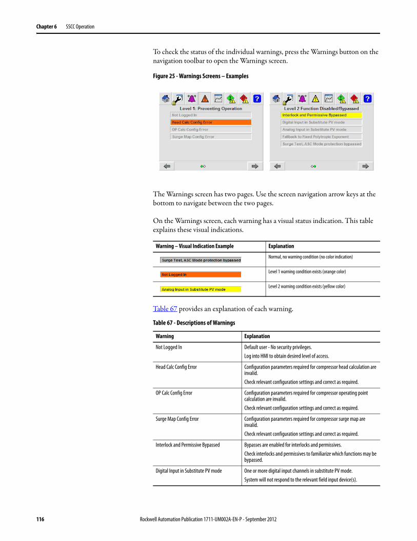
Chapter 6 SSCC Operation
To check the status of the individual warnings, press the Warnings button on the navigation toolbar to open the Warnings screen.
Figure 25 - Warnings Screens – Examples
The Warnings screen has two pages. Use the screen navigation arrow keys at the bottom to navigate between the two pages.
On the Warnings screen, each warning has a visual status indication. This table explains these visual indications.
Table 67 provides an explanation of each warning.
Warning – Visual Indication Example Explanation
Normal, no warning condition (no color indication)
Level 1 warning condition exists (orange color)
Level 2 warning condition exists (yellow color)
Table 67 - Descriptions of Warnings
Warning Explanation
Not Logged In Default user - No security privileges.Log into HMI to obtain desired level of access.
Head Calc Config Error Configuration parameters required for compressor head calculation are invalid.Check relevant configuration settings and correct as required.
OP Calc Config Error Configuration parameters required for compressor operating point calculation are invalid.Check relevant configuration settings and correct as required.
Surge Map Config Error Configuration parameters required for compressor surge map are invalid.Check relevant configuration settings and correct as required.
Interlock and Permissive Bypassed Bypasses are enabled for interlocks and permissives.Check interlocks and permissives to familiarize which functions may be bypassed.
Digital Input in Substitute PV mode One or more digital input channels in substitute PV mode.System will not respond to the relevant field input device(s).
116 Rockwell Automation Publication 1711-UM002A-EN-P - September 2012

SSCC Operation Chapter 6
Check and Reset a Warning Example
The following sequence provides an example of checking warning indications.
Analog Input in Substitute PV mode One or more analog input channels in substitute PV mode.System will not respond to actual field transmitter signal(s).
Fallback to fixed polytropic exponent A failed transmitter exists which prevents the system from calculating a polytropic exponent from actual pressure and temperature measurements.A fixed polytropic exponent calculation is used f(k, Peff). This may affect the accuracy of the head calculation.
Surge Test: ASC mode protection bypassed Surge test is enabled, bypassing the normal protection limits for Manual mode operation of the anti-surge primary PID loop.In this condition, it is possible to drive the compressor into surge by operating the ASC primary PID loop in Manual mode.
Screen Indications Observations and Actions
The unit warning status on the navigation toolbar informs the user that:- Warnings are present (yellow)Press the Warnings icon to open the Warnings screen.
Page 1: Preventing Operation - No warnings
Page 2: Function Disabled/ Bypassed - warningAnalog input in Substitute mode indicates that one or more of the configured analog input channels is using a substitute PV, bypassing the actual input PV from the transmitter.
Table 67 - Descriptions of Warnings (Continued)
Warning Explanation
Rockwell Automation Publication 1711-UM002A-EN-P - September 2012 117

Chapter 6 SSCC Operation
Compressor Start and Stop The SSCC is primarily responsible for anti-surge and capacity control for the compressor. Typically another controller or interlock system is used to start and stop the drive (motor, turbine, etc.) that turns the compressor.
The SSCC provides interface I/O to coordinate the following signals with the drive controller.
• Ready-to-start digital output signal to the drive controller. This signal is controlled based on the unit permissive status.
• Compressor trip digital output signal to the drive controller. This signal is controlled based on the unit interlock status.
• Compressor running digital input signal from the drive controller.
The compressor state of operation is influenced by the interlocks (trip), permissives (ready-to-start), running determination, and load/unload requests.
It is highly recommended that alarms or warnings be cleared before starting the compressor. The toolbar icons for alarm and warning should be white indicating that none of these categories has active items.
Navigation to the Maintenance/Configuration ScreenUsing the Device Operation & Settings selector field to browse the analog input devices:Compressor FlowSuction PressureDischarge PressureAuxiliary Control SignalSuction TemperatureDischarge TemperatureMulti-Use Signal AMultiUse Signal B
Through browsing the analog input devices, it is observed that the suction pressure input is in Substitute PV mode.Check with operations and maintenance to identify if it is safe to operate the unit in this condition.
Screen Indications Observations and Actions
118 Rockwell Automation Publication 1711-UM002A-EN-P - September 2012

SSCC Operation Chapter 6
When the compressor is ready to start, the Compressor Overview screen should appear as shown in Figure 26.
Figure 26 - Compressor Overview – Ready to Start
The following key indications are present when the compressor is ready to start.
ATTENTION: Do not attempt to start the compressor if the unit’s configuration has not been completed. All relevant configuration parameters discussed in this chapter must be properly configured. Failure to do so may cause equipment damage or personal injury.
ATTENTION: Visual confirmation of the anti-surge valve position and capacity valve position is recommended before starting the compressor. Failure to do so may cause equipment damage or personal injury.
Indication Description
Alarm Status Alarms clearIf alarms are present, they have been checked, understood, and operations ready to proceed.
Warning Status No warningsIf warnings are present, they have been checked, understood, and operations ready to proceed.
Interlock Status Interlocks OK, or all non-bypassed OK.
Compressor trip output, Not-Tripped
Permissive Status Permissives – Ready, or all non-bypassed – Ready
Ready-to-Start output, Ready
ASC Valve Anti-surge valve CV at pre-start override value.
Capacity Valve/Device(if configured)
Capacity valve/device CV at pre-start override value.
Rockwell Automation Publication 1711-UM002A-EN-P - September 2012 119

Chapter 6 SSCC Operation
Compressor Running Determination
Compressor running condition is determined by one or more of the following conditions.
• Compressor running digital input status
• Compressor head calculation > threshold
• Auxiliary control signal > threshold
When one of the above conditions is met for the configured on-delay time, then a confirmed compressor running status is determined.
These specific running determination methods are configured in 14: Run and Load Configuration on page 68.
The confirmed compressor running status is annunciated on the Compressor Overview - Operator (page 2) screen. In addition to this HMI annunciation, the compressor running digital output (DOUT channel 4) is energized for external indication/usage.
Figure 27 - Compressor Overview – Running Status
Once reaching the running state the compressor is ready for loading.
120 Rockwell Automation Publication 1711-UM002A-EN-P - September 2012

SSCC Operation Chapter 6
Compressor Load/Unload After the compressor running condition is established and there are no compressor trip conditions, the compressor is available to load. Loading the compressor can be accomplished in one of the following ways, based on configured options.
• Auto-load on confirmed run - Load is automatically triggered after the confirmed running condition described previously.
• Load push-button - Digital input channel 2 may be wired to an external push button to manually request compressor load.
• Load button on HMI - Load button on Compressor Overview - Operator screen is pressed to manually request compressor load.
The confirmed compressor load status is annunciated on the Compressor Overview - Operator screen (page 2). In addition to this HMI annunciation, the compressor loaded digital output (DOUT channel 5) is energized for external indication/usage.
Once the compressor is set to load, the anti-surge and capacity valve/devices are released from their respective override values, and available for regulatory control by the configured anti-surge and capacity control PID functions.
Figure 28 - Compressor Overview – Compressor Loaded Status
The Operator screens and PID faceplates can now be used to control and adjust the operating behavior of the compressor.
Rockwell Automation Publication 1711-UM002A-EN-P - September 2012 121

Chapter 6 SSCC Operation
Device Faceplates The HMI provides several device faceplates to operate and configure devices. The following tables provide an overview of these device faceplates and their features.
Table 68 - Analog Input Device Faceplate
Tab Sample Screen Description
Input PV Mode
Substitute PV Mode
Analog Input Device Faceplate – Operator tabDisplay Features:• Banner with device name • Bar graph display of PV value in use• High and low alarm value setpoint values, and level
indicators on bar graph• Indicators for Over-range, Under-range, IO Fault, and
Channel Not Configured For Use when conditions are present
• Visual indication of Input PV or Substitute PV modes
Operational Features: • Use Mode select buttons to choose between PV
from input, or Substitute PV mode - security privilege required (M, E, or A).
• In Substitute PV mode, enter the substitute PV value - security privilege required (M, E, or A).
Analog Input Device Faceplate – Configuration tabDisplay Features:• Configuration parameter values viewable regardless of
security privilege
Configuration Features: • Customize the device name, and unit of measure strings -
security privilege required (E or A).• Configure engineering unit scaling - security privilege
required (E or A).• Configure alarm settings - security privilege required (E or
A)
122 Rockwell Automation Publication 1711-UM002A-EN-P - September 2012

SSCC Operation Chapter 6
Table 69 - Analog Output Device Faceplate
Tab Sample Screen Description
Program Mode
Operator Mode
Analog Output Device Faceplate – Operator tabDisplay Features:• Banner with device name • Bar graph display of CV value in use• Valve position feedback value (when configured)• Indicator for IO Fault when condition present• Visual indication of Program or Operator modes
Operational Features:
• Use and to choose between Program and Operator mode - security privilege required (O, S, M, or E).
• In Operator mode, enter the manual CV value - security privilege required (O, S, M, or E).
Analog Output Device Faceplate – Configuration tabDisplay Features:• Configuration parameter values viewable regardless of
security privilegeConfiguration Features:
• Customize the device name, and unit of measure strings - security privilege required (E or A).
• Other configurable properties for reference only. Some available from compressor details device faceplate.
Rockwell Automation Publication 1711-UM002A-EN-P - September 2012 123

Chapter 6 SSCC Operation
Table 70 - Digital Input Device Faceplate
Tab Sample Screen Description
Input PV Mode
Substitute PV Mode
Digital Input Device Faceplate – Operator tabDisplay Features:• Banner with device name• Device state represented with descriptive word• Indicators for IO Fault, and Channel Not Configured For
Use when conditions present• Visual indication of Input PV or Substitute PV modes
Operational Features:
• Use to choose between PV from Input, or Substitute PV mode - security privilege required (M, E, or A).
• In Substitute PV mode, use state buttons to set substitute PV state - security privilege required (M, E, or A).
Digital Input Device Faceplate – Configuration tabDisplay Features:• Configuration parameter values viewable regardless of
security privilege
Configuration Features: • Customize the device name - security privilege required (E
or A).• Configure channel usage, active state, and use of
Substitute PV mode - security privilege required (E or A).
124 Rockwell Automation Publication 1711-UM002A-EN-P - September 2012

SSCC Operation Chapter 6
Table 71 - Digital Output Device Faceplate
Tab Sample Screen Description
Program Mode
Operator Mode
Digital Output Device Faceplate – Operator tabDisplay Features:• Banner with device name• Indication of device state; Activated or Deactivated• Indicator for IO Fault when condition present• Visual indication of Program or Operator modes
Operational Features:
• Use and to choose between Program and Operator mode - security privilege required (O, S, M or E).
• In Operator mode, use and to set output value - security privilege required (O, S, M or E).
Digital Output Device Faceplate – Configuration tabDisplay Features:• Configuration parameter values viewable regardless of
security privilege
Configuration Features: • Customize the device name - security privilege required (E
or A).• Configure device operation/fail state.
Rockwell Automation Publication 1711-UM002A-EN-P - September 2012 125

Chapter 6 SSCC Operation
Table 72 - PID Loop Faceplate
Tab Sample Screen Description
Auto Mode
Manual Mode
PID Loop Faceplate – Operator tabDisplay Features:• Banner with loop name• Indication of Loop mode• Values for SP, PV, CV• Vertical bar graph of PV with setpoint slider• Horizontal bar graph of CV• Visual indication of Program or Operator modes
Operational Features: • Use to choose between Auto and Manual mode - security
privilege required (O, S, M, or E).• In Auto mode, use SP value entry - security privilege
required (O, S, M, or E).• In Manual mode, use CV value entry - security privilege
required (O, S, M, or E).
Anti-Surge Primary PID Loop
Other PID Loops
PID Loop Faceplate – Configuration/Tuning tabDisplay Features:• Configuration parameter values viewable regardless of
security privilege
Configuration Features: • Customize the loop name and units for PV and CV -
security privilege required (E or A).• Adaptive tuning parameters (ASC primary PID loop)• Standard tuning parameters (other PID loops)• Setpoint configuration parameters (other PID loops)
126 Rockwell Automation Publication 1711-UM002A-EN-P - September 2012

SSCC Operation Chapter 6
Table 73 - Compressor Details Faceplate
Tab Sample Screen Description
Compressor Details Faceplate – Head tabConfiguration Features:• Head calculation properties - security privilege required
(E or A).• Pressures and temperatures in absolute units.• Head calculation values .• Head calc configuration error indications if present.
Compressor Details Faceplate – Base Conditions tabConfiguration Features:• Flow element location type.• Flow element configuration (base press and temp, max
flow for normalization) - security privilege required (E or A).
• Compressor base configuration (base press and temp, gas properties) - security privilege required (E or A).
• IGV method configuration - security privilege required (E or A).
• OP calc configuration error indications if present.
Compressor Details Faceplate – Map tabConfiguration Features:• Compressor map surge limit line configuration - security
privilege required (E or A).• Map configuration error indications if present.
Compressor Details Faceplate – OP Tracking / Decoupling tabConfiguration Features:• OP tracking tuning properties - security privilege required
(M, E, or A).• Decoupling tuning properties - security privilege required
(M, E, or A).• Use decoupling configuration property - security privilege
required (E or A).• Decoupling status.
Rockwell Automation Publication 1711-UM002A-EN-P - September 2012 127

Chapter 6 SSCC Operation
Accessing Device Faceplates
The device faceplates provide graphical detail of both operational and configurable features for a particular I/O device, PID loop, or the compressor details.
To access the faceplates within the HMI, follow these steps to navigate to the Maintenance screen, and successfully open the faceplate of choice.
1. Press to close any open pop-up screens and return to a main screen showing the navigation toolbar.
2. Press on the navigation toolbar.
The Maintenance screen appears.
Compressor Details Faceplate – Anti-Surge / Capacity Valve tabConfiguration Features:• Anti-surge valve configuration properties (slew rates,
control limits, position deviation alarm settings) - security privilege required (M, E, or A).
• Capacity calve / IGV configuration properties (slew rates, control limits, position deviation alarm settings) - security privilege required (M, E, or A).
Compressor Details Faceplate – Surge Configuration tabConfiguration Features:• Multi-surge trip configuration properties - security
privilege required (E or A).• Rate-of-change and positional surge properties - security
privilege required (M, E, or A).
Operational Features: • Press the reset button to reset the compressor surge
counter - security privilege required (E, or A).
Compressor Details Faceplate – Surge Test tabDisplay Features:• Surge testing status and configuration.• Live/Trapped operational data from surge test.
Operational Features:
• Activate and Deactivate surge test buttons - security privilege required (E, or A).
• Choose from positional, rate-of-change, and incipient surge methods for surge test capture - security privilege required (E or A).
• Press to reset surge test data - security privilege required (E or A).
Table 73 - Compressor Details Faceplate (Continued)
Tab Sample Screen Description
128 Rockwell Automation Publication 1711-UM002A-EN-P - September 2012

SSCC Operation Chapter 6
3. Press to page forward, or to page backward, as required to navigate to page one of the Maintenance screen (shown here).
4. Press to select the device you want to access in the Device Operation & Settings selector list at the bottom of the screen.
5. Press to open the selected device faceplate.
Accessing the PID Faceplates from the Operator Screen
For convenience, the PID faceplates and the compressor details faceplate can be accessed from certain Operator screens. Follow these steps to access the PID faceplates.
1. Press to close any open pop-up screens and return to a main screen showing the navigation toolbar.
2. Press on the main navigation toolbar to navigate to the Operator screen.
3. Press to page forward, or to page backward, as required to navigate to the Operator screen, Anti-Surge PID Overview (page 5), or the Capacity PID Overview screen (page 6), shown here.
Note, only those PID loops that are configured will be shown on these screens.
4. Press to open the desired PID faceplate.
Rockwell Automation Publication 1711-UM002A-EN-P - September 2012 129

Chapter 6 SSCC Operation
Accessing the Compressor Details Faceplates from the Operator Screen
1. Press to close any open pop-up screens and return to a main screen showing the navigation toolbar.
2. Press on the main navigation toolbar to navigate to the Operator screen.
3. Press to page forward, or to page backward, as required to navigate to the Operator screen - Compressor Map Overview (page 3), shown here.
4. Press to open the Compressor Details faceplate.
Device Names and Device Selector
The Device Operation & Settings (device) selector on the Maintenance screen presents the devices by the device name. From the device faceplates the names can be customized, and even made blank. If after customization the device names are changed and it becomes difficult to identify the devices presented in the device selector, the following list can be helpful to re-orient and identify the devices.
The device selector presents the devices in a pre-determined order. The order and default names for each device are shown in Table 74 on page 131.
Each time you navigate to the Maintenance screen from another main screen, the device order resets to the start of the list at the device allocated for compressor flow.
130 Rockwell Automation Publication 1711-UM002A-EN-P - September 2012

SSCC Operation Chapter 6
Table 74 - Order of Devices on the Device Selector
Order Device Name (default) Description of Device
1 Compressor Flow AIN channel 0, allocated for Compressor Flow
2 Suction Pressure AIN channel 1, allocated for Suction Pressure
3 Discharge Pressure AIN channel 2, allocated for Discharge Pressure
4 Auxiliary Control PV Signal AIN channel 3, allocated for an additional process transmitter which can be used as a PV for control loops.
5 Suction Temperature AIN channel 4, allocated for Suction Temperature
6 Discharge Temperature AIN channel 5, allocated for Discharge Temperature
7 Multi-Signal A AIN channel 6, configurable usage
8 Multi-Signal B AIN channel 7, configurable usage
9 Antisurge Control valve AOUT channel 0, allocated for Anti-Surge Valve
10 Capacity Control valve AOUT channel 1, allocated for Capacity control device
11 Compressor Run DI DIN channel 0, allocated for Compressor Run input from the drive system
12 Reset Push Button DIN channel 1, allocated for external Reset P.B.
13 Load Request Push Button DIN channel 2, allocated for external Load P.B.
14 Unload Request Push Button DIN channel 3, allocated for external Unload P.B.
15 External Ready To Start 1 DIN channel 8, allocated for Ready To Start 1, a Permissive
16 External Ready To Start 2 DIN channel 9, allocated for Ready To Start 2, a Permissive
17 External Ready To Start 3 DIN channel 10, allocated for Ready To Start 3, a Permissive
18 External Ready To Start 4 DIN channel 11, allocated for Ready To Start 4, a Permissive
19 External Compressor Trip 1 DIN channel 12, allocated for Compressor Trip 1, an Interlock
20 External Compressor Trip 2 DIN channel 13, allocated for Compressor Trip 2, an Interlock
21 External Compressor Trip 3 DIN channel 14, allocated for Compressor Trip 3, an Interlock
22 External Compressor Trip 4 DIN channel 15, allocated for Compressor Trip 4, an Interlock
23 Compressor Trip DO DOUT channel 0, allocated for Compressor Trip Interlock signal to the drive controller.
24 Surge Alarm DOUT channel 1, allocated for optional Surge Alarm status indication
25 System Trouble DOUT channel 2, allocated for optional System Trouble status indication
26 Ready To Start DO DOUT channel 3, allocated for Ready To Start Permissive signal to the drive controller
27 Compressor Running DO DOUT channel 4, allocated for optional Compressor Running status indication
28 Compressor Loaded DOUT channel 5, allocated for optional Compressor Loaded status indication
29 AntiSurge Primary Loop Anti-Surge Primary PID Loop, allocated to pre-configured algorithm to control Operating Point (OP) as PV relative to Surge Control Line (SCL) as the SP. Controls the Anti-Surge valve.
30 AntiSurge Secondary Loop Optional Anti-Surge Secondary PID Loop. Configurable PV choice. Used as over-ride PID in a Max select arrangement with the Anti-Surge Primary PID Loop.
31 Capacity Primary Loop Optional Capacity Primary PID Loop. Configurable PV choice. Controls the Capacity control valve / IGV.
32 Capacity Secondary Loop Optional Capacity Secondary PID Loop. Configurable PV choice. Use as over-ride PID in a Min/Max select arrangement with the Capacity Primary PID Loop.
33 Compressor Details Compressor configuration and information details popup.
Rockwell Automation Publication 1711-UM002A-EN-P - September 2012 131

Chapter 6 SSCC Operation
Analog Input Device Faceplate
The Analog Input Device faceplate provides a graphical interface to the operational and configurable behaviors of the analog input channels.
Analog Input Device Operation
Press to display the Operations page. The following illustration details the features of the Device Operation page.
Figure 29 - Analog Input Faceplate – Operations Page
The analog input device supports two modes of operation: 1) PV from Input, and 2) Substitute PV.
Under normal operations, the mode should be PV from Input. This mode uses the measured input signal raw count (0…10000), and converts it to engineering units according to the configured scaling settings. The scaled value is presented as the process value (PV) in use.
Substitute PV mode lets you to override the measured value, and substitute in its place, a desired engineering unit value. This mode may be useful should a transmitter fail, require maintenance, or calibration. Use of Substitute PV mode produces a warning.
Through configuration (refer to parameter list 24: AINs - Substitute PV) the use of Substitute PV mode can be disallowed. When disallowed, the Substitute PV features are absent from the device operation graphic and the device mode will be PV from Input.
The mode operation buttons and Substitute PV value entry require security privileges (maintenance, engineer, or administrator).
Channel Not Configured Indicator
Over-range indicator
Channel Fault indicator
Under-range indicator
Engineering Unit Scale
Close Screen
Device NameHi Alarm LimitPV Value in Use
Lo Alarm Limit
Mode Operation
Substitute PV valueInput Signal raw count (0…10000)
Unit of Measure
132 Rockwell Automation Publication 1711-UM002A-EN-P - September 2012

SSCC Operation Chapter 6
When the device is in PV from Input mode, the Substitute PV value automatically tracks the scaled PV value. This makes the transition to Substitute PV mode bumpless.
Analog Input Device Configuration
Press to display the Configuration page. Many of the analog input channel configuration parameters may be adjusted on this page.
Figure 30 - Analog Input Faceplate – Configuration Page
Table 75 lists the configuration items displayed on the Analog Input Faceplate - Configuration page and the corresponding parameter used for configuration. The parameters listed in the table are contained in the 01: AIN - Compressor Flow parameter list.
Customize the Channel
From the device configuration, you may edit the description, and the units of measure. These represent string tags in the HMI (not the controller). These tags are retentive and saved in the HMI memory. For example, you may want to include the device tag number in the description (for example: “FT-1007 Compressor Flow”), and set the units of measure (for example: “acfm”).
Table 75 - Analog Input Faceplate to Parameter Cross Reference
Faceplate Configuration Item Configuration Parameter
Scaled EU - Maximum 02: Eng Unit Scale Max (EU)
Scaled EU - Minimum 03: Eng Unit Scale Min (EU)
Has Extend Scaling (check box) 05: Extrap Scaling (1=Yes)
Square Root Extract (check box) 04: Scaling (0=Linear, 1=Sqrt)
Has Hi Alarm (check box) 07: Has Alarm High (1=Yes)
Has Lo Alarm (check box) 08: Has Alarm Low (1=Yes)
Hi Alarm Limit (value) 09: High Alarm Limit (EU)
Lo Alarm Limit (value) 10: Low Alarm Limit (EU)
Alarm DB 11: Alarm Deadband (EU)
Scaling Configuration
Alarm Configuration
Close Screen
Edit Device Name
Edit Units of Measure
Rockwell Automation Publication 1711-UM002A-EN-P - September 2012 133

Chapter 6 SSCC Operation
String Tag limits are:Description: 34 charactersUnit of Measure: 6 characters
Analog Output Device Faceplate
The Analog Output Device faceplate provides a graphical interface to the operational and configurable behaviors of the analog output channels.
Analog Output Device Operation
Press to display the Operations page. The following illustration details the features of the Device Operation page.
Figure 31 - Analog Output Faceplate – Operations Page
The analog output device supports two modes of operation: 1) Program, and 2) Operator.
Under normal operations, the mode should be Program. In Program mode the application program and interlocks determine the control value (CV) in use. When the device is in Program mode, the operator CV value automatically tracks the CV value in use. This makes the transition to Operator mode bumpless.
Operator mode is intended only for device maintenance and testing when the compressor is not running. When in Operator mode, the operator CV value can be entered from the screen. Use of Operator mode sets the permissive, analog outputs OK, to Not-Ready.
When the compressor is running, the device mode is automatically set to Program mode, and the Mode control button is not available. When the compressor is not running, the mode control button is presented on the screen.
Mode control button
Mode status indication
Close Screen
Device Name
CV In Use & UnitsPosition Feedback(if configured)
Channel Fault indicator
Operator CV value
134 Rockwell Automation Publication 1711-UM002A-EN-P - September 2012

SSCC Operation Chapter 6
The mode operation buttons and operator CV value entry require security privileges (operator, supervisor, maintenance, or engineer).
Analog Output Device Configuration
Press to display the Configuration page. Configuration parameters relating to the valve devices can be observed on this page. Note, these configuration parameters are not changed on this page. See Table 76.
Figure 32 - Analog Output Faceplate – Configuration Page
Current Mode Mode Button Button Action
Program None The compressor is running, mode change not available.
Program Pressing the button switches the mode to Operator.
Operator Pressing the button switches the mode to Program.
Control Valve Configuration Properties
Close Screen
Edit Device Name
Edit Units
Position Alarm Configuration Properties
Rockwell Automation Publication 1711-UM002A-EN-P - September 2012 135

Chapter 6 SSCC Operation
Table 76 lists the configuration items displayed on the Analog Output Faceplate - Configuration page and the corresponding parameter lists and parameter numbers used for configuration.
Customize the Channel
From the device configuration, you may edit the description, and the units of measure. These represent string tags in the HMI (not the controller). These tags are retentive and saved in the HMI memory. For example, you may want to include the device tag number in the description (for example: “FCV-1007 AntiSurge Valve”), and set the units of measure (for example: “% Open”).
String Tag limits are:
Description: 34 characters
Unit of Measure: 6 characters
Table 76 - Analog Output Faceplate Configuration Parameter List Cross Reference
Faceplate Configuration Item Parameter List / Parameter
CV Range – Maximum None, set in logic, 100.0% Open
CV Range – Minimum None, set in logic, 0.0% Open
Fail Open (check box) Anti-Surge ValveList: 15, Parameter: 10Valve Fail: (0=Clsd,1-Opn)
Capacity Valve / IGVList: 20, Parameter: 09Valve Fail: (0=Clsd,1-Opn)
Has Low Res AO (check box) None, not used
Has Position Feedback (check box) None, set in logic based on Multi-Sig AIN usage for position feedback signals.
Position Deviation DB Anti-Surge ValveList: 15, Parameter: 11Pos Dev Alm DB (%)
Capacity Valve / IGVList: 20, Parameter: 10Pos Dev Alm DB (%)
Deviation Minimum Duration (Sec) Anti-Surge ValveList: 15, Parameter: 12Pos Dev Alm Time (sec)
Capacity Valve / IGVList: 20, Parameter: 11Pos Dev Alm Time (sec)
136 Rockwell Automation Publication 1711-UM002A-EN-P - September 2012

SSCC Operation Chapter 6
Digital Input Device Faceplate
The Digital Input Device faceplate provides a graphical interface to the operational and configurable behaviors of the digital input channels.
Digital Input Device Operation
Press to display the Operations page. The following illustration details the features of the Device Operation page.
Figure 33 - Digital Input Faceplate – Operations Page
The digital input device supports two modes of operation: 1) PV from Input, and 2) Substitute PV.
Under normal operations, the mode should be PV from Input. This mode uses the actual input signal applying the configured input state. The value is presented as the process value (PV) in use.
Substitute PV mode allows the user to override the input value, and substitute in its place, the desired value. This mode may be useful should a device fail, require maintenance, or troubleshooting. Use of Substitute PV mode produces a warning.
Through configuration (refer to parameter list 25: DINs - Substitute PV) the use of Substitute PV mode can be disallowed. When disallowed, the substitute PV features are absent from the device operation graphic and the device mode will be PV from Input.
The mode operation buttons and substitute PV value buttons require security privileges (maintenance, engineer, or administrator).
When the device is in PV from Input mode, the substitute PV value automatically tracks the scaled PV value. This makes the transition to Substitute PV mode bumpless.
Channel Not Configured Indicator
Input Signal State
Channel Fault Indicator
Close Screen
Device Name
PV Value in Use
Mode Operation
Substitute PV Control
Rockwell Automation Publication 1711-UM002A-EN-P - September 2012 137

Chapter 6 SSCC Operation
Digital Input Device Configuration
Press to display the Configuration page. Many of the digital input channel configuration parameters may be adjusted on this page.
Figure 34 - Digital Input Faceplate – Configuration Page
Table 77 lists the configuration items displayed on the Digital Input Faceplate - Configuration page and the corresponding parameter lists and parameter numbers used for configuration.
Customize the Channel
From the device configuration, you may edit the description. This represents a string tag in the HMI (not the controller). This tag is retentive and saved in the HMI memory. For example, you may want to include the device tag number in the description and identify the signal more clearly (for example: “PSL-1014 Low Lube Oil Pressure”).
String Tag limits are:
Description: 34 characters
Table 77 - Digital Input Faceplate Configuration Parameter List Cross Reference
Faceplate Configuration Item Parameter List / Parameter
Disallow Substitute PV List: 25: DINs, subst PV (0=Allow, 1=DisAllow)Parameter: various, individual per channel
DI = 1 = Active Status List: 09: Digital Input Channel ConfigurationParameter: various, individual per channel
Use This Signal List: 09: Digital Input Channel ConfigurationParameter: various, individual per channel
Channel Configuration
Close Screen
Edit Device Name
Disallow Substitute PV mode
138 Rockwell Automation Publication 1711-UM002A-EN-P - September 2012

SSCC Operation Chapter 6
Digital Output Device Faceplate
The Digital Output Device faceplate provides a graphical interface to the operational and configurable behaviors of the digital output channels.
Digital Output Device Operation
Press to display the Operations page. The following illustration details the features of the Device Operation page.
Figure 35 - Digital Output Faceplate – Operations Page
The digital output device supports two modes of operation: 1) Program, and 2) Operator.
Under normal operations, the mode should be Program. In Program mode the application program and interlocks determine the control value (CV) in use. When the device is in Program mode, the operator CV value automatically tracks the CV value in use. This makes the transition to Operator mode bumpless.
Operator mode is intended only for device maintenance and testing when the compressor is not running. When in Operator mode, the operator control buttons can be used to set the control value. Use of Operator mode sets the permissive, digital outputs OK, to not-ready.
When the compressor is running, the device mode is automatically set to Program mode, and the mode control button is not available. When the compressor is not running, the mode control button is presented on the screen.
Current Mode Mode Button Button Action
Program None The compressor is running, mode change not available.
Program Pressing the button switches the mode to Operator.
Operator Pressing the button switches the mode to Program.
Control Value in Use
Mode Control Button
Close Screen
Device Name
Channel Fault Indicator
Operator Control Buttons
Mode Status Indication
Rockwell Automation Publication 1711-UM002A-EN-P - September 2012 139

Chapter 6 SSCC Operation
The mode buttons and operator control buttons require security privileges (operator, supervisor, maintenance, or engineer).
Digital Output Device Configuration
Press to display the Configuration page. Many of the digital output channel configuration parameters may be adjusted on this page.
Figure 36 - Digital Output Faceplate – Configuration Page
Table 78 lists the configuration items displayed on the Digital Output Faceplate - Configuration page and the corresponding parameter lists and parameter numbers used for configuration.
Customize the Channel
From the device configuration, you may edit the description. This represents a string tag in the HMI (not the controller). This tag is retentive and saved in the HMI memory. For example, you may want to include the device tag number in the description and identify the signal more clearly (for example: “XA-1004 Surge Alarm”).
String tag limits are:
Description: 34 characters
Table 78 - Digital Output Device Configuration Parameter List Cross Reference
Faceplate Configuration Item Parameter List / Parameter Number
Fail On List: 10: Digital Output Channel ConfigurationParameter: various, individual per channel
Control ValueConfiguration
properties
Close Screen
Edit Device Name
140 Rockwell Automation Publication 1711-UM002A-EN-P - September 2012

SSCC Operation Chapter 6
PID Loop Faceplate
The PID Loop faceplate provides a graphical interface to the anti-surge and capacity control PID loops. The PID faceplate has an Operations page and a Configuration page.
PID Loop Device Operation
Press to display the Operations page. The following illustration details the features of the PID loop Operation page.
Figure 37 - PID Faceplate – Operations Page
The PID loop is a Proportional - Integral - Derivative controller used for regulatory control applications. The PID loop is used for both anti-surge and capacity control within the SSCC system.
Loop Mode
The mode buttons provide both control and indication of the Loop mode.
Mode Buttons Indication Description Operation available
Loop is in Manual None, security privilege required (O, S, M or E)
Loop is in Auto None, security privilege required (O, S, M or E)
Loop is in Manual Press to switch to Auto Mode
Loop is in Auto Press to switch to Manual Mode
Setpoint Entry (Auto Mode)
Mode Control Button
Close Screen
Device Name
Process Variable & Units
Control Value Entry (Manual Mode)
Setpoint In Use
Control Value in Use
Rockwell Automation Publication 1711-UM002A-EN-P - September 2012 141

Chapter 6 SSCC Operation
For the anti-surge primary PID loop, the application provides a mode protection feature to switch the loop from Manual back to Auto mode when the operating point is within a certain distance of the surge limit line. This prevents the operator from driving the compressor into surge. This protection feature is bypassed when surge testing is enabled. The anti-surge secondary PID loop and the capacity PID loops do not incorporate this mode protection.
When all configured loops are in Auto mode, the control loops ready permissive is generated. If operational procedures for the compressor require one or more of the configured loops to be in Manual mode at startup, then this permissive may need to be configured for bypass.
Loop Setpoint
When the PID loop is in Auto mode, the setpoint of the loop may be adjusted (security privilege required: O, S, M or E). Setpoint entry is limited by the configured SP Minimum and SP Maximum values. When a new setpoint is entered, the setpoint in use will adjust to the new target value at the configured SP Increase and Decrease limits.
For the anti-surge primary PID loop, the loop setpoint is determined by the application logic (SCL value from the OP tracking function). While the faceplate provides SP entry, the application will over write any entered value from the HMI.
Manual Control Value
When the loop is in Manual mode, the manual control value can be adjusted (security privilege required: O, S, M or E). Control value entry is limited by the configured CV Minimum and CV Maximum values.
PID Loop Device Configuration
Press to display the Configuration page. There are two types of Configuration pages for the PID loop: 1) Standard Tuning, 2) Adaptive Tuning. The anti-surge primary PID loop uses the Adaptive Tuning configuration page, and the other PID loops use the Standard Tuning configuration page.
Configuration Page – Adaptive Tuning
The following illustration details the features of the PID Adaptive Tuning Configuration page used for the anti-surge primary PID loop.
142 Rockwell Automation Publication 1711-UM002A-EN-P - September 2012

SSCC Operation Chapter 6
Figure 38 - PID Faceplate – Adaptive Tuning Configuration Page
Adaptive tuning is used to automatically adjust the proportional and integral tuning values based on operating conditions. The adaptive tuning adjustment principles are illustrated in the following figure.
Figure 39 - Adaptive Tuning Principles
The controller calculates the difference between the operating point and the surge control line = (OP – SCL). These values are shown on the Configuration page. When difference between the operating point and the surge control line (Diff ) is between the breakpoints, the base tuning value is used. When the Diff is
Close Screen
Edit Device Name
Edit Units of Measure
Values influencing Adaptive Tuningcalculation
Base Tuning Values
Adaptive Tuning values
Maximum Limit, Kmax
Minimum Limit, Kmin
Base value, Kbase
0BP1,Breakpoint 1
BP2, Breakpoint 2
Slope 2, S2
Slope 1, S1
( - ) ( + )
Rockwell Automation Publication 1711-UM002A-EN-P - September 2012 143

Chapter 6 SSCC Operation
outside the breakpoints, the tuning value is calculated based on the slopes S1 or S2. A positive value for slope increases the tuning value (slope 1 in the illustration). A negative value for slope decreases the tuning value (slope 2 in the illustration). The calculated adaptive tuning value is shown as Kcalc on the Configuration page. The calculated value is clamped at the configured minimum and maximum limits.
Table 79 lists the configuration items displayed on the PID Loop Faceplate - Adaptive Tuning Configuration page and the corresponding parameter lists and parameter numbers used for configuration.
Customize the Loop
From the device configuration, you may edit the description, and the units of measure. These represent string tags in the HMI (not the controller). These tags are retentive and saved in the HMI memory. For example, you may want to include the device tag number in the description (for example: “UIC-1007 AntiSurge Control”). You may also set the units of measure if desired. Note that for the anti-surge primary PID loop, the PV is always the calculated operating point, which is normalized 0…100% value. The control value of the PID loop is intended to represent a control signal as 0…100% open.
String Tag limits are:
Description: 34 characters
Unit of Measure: 6 characters
Table 79 - PID Loop - Adaptive Tuning Configuration Parameter List Cross Reference
Faceplate Configuration Item Security Parameter List / Parameter
Proportional – BP1 E or A List 18, Param 04: BreakPoint 1 (%)
Proportional – S1 E or A List 18, Param 06: Slope 1 (Gain / %)
Proportional – BP2 E or A List 18, Param 05: BreakPoint 2 (%)
Proportional – S2 E or A List 18, Param 07: Slope 2 (Gain / %)
Proportional – Max E or A List 18, Param 02: Max Proportional (Gain)
Proportional – Min E or A List 18, Param 03: Min Proportional (Gain)
Proportional - Base M, E or A List 18, Param 01: Base Proportional (Gain)
Integral – BP1 E or A List 17, Param 04: BreakPoint 1 (%)
Integral – S1 E or A List 17, Param 06: Slope 1 (Rpt/min / %)
Integral – BP2 E or A List 17, Param 05: BreakPoint 2 (%)
Integral – S2 E or A List 17, Param 07: Slope 2 (Rpt/min / %)
Integral – Max E or A List 17, Param 02: Max Integral (Rpt/min)
Integral – Min E or A List 17, Param 03: Min Integral (Rpt/Min)
Integral – Base M, E or A List 17, Param 01: Base Integral (Rpt/min)
144 Rockwell Automation Publication 1711-UM002A-EN-P - September 2012

SSCC Operation Chapter 6
Configuration Page – Standard Tuning
The following illustration details the features of the PID Standard Tuning Configuration page used with the anti-surge secondary PID loop and both capacity PID loops.
Figure 40 - PID Faceplate – Standard Tuning Configuration Page
Table 80 lists the configuration items displayed on the PID Loop Faceplate - Standard Tuning Configuration page and the corresponding parameter lists and parameter numbers used for configuration.
Table 80 - PID Loop - Standard Tuning Configuration Parameter List Cross Reference
Faceplate Configuration Item Security Parameter List Cross ReferenceList 19: Anti-Surge Secondary PID LoopList 21: Capacity Primary PID LoopList 22: Capacity Secondary PID Loop
SP Max Limit M, E or A Param 04: SP Max Limit (EU)
SP Min Limit M, E or A Param 05: SP Min Limit (EU)
SP Inc Rate M, E or A Param 06: SP Inc Limit (EU/sec)
SP Dec Rate M, E or A Param 07: SP Dec Limit (EU/sec)
Track PV in Manual (check box) E or A Param 03: SP Track PV in Man(1=Y)
Proportional M, E or A Param 08: Proportional (Gain)
Integral M, E or A Param 10: Integral (Rpt/min)
Derivative M, E or A Param 11: Derivative (sec)
Interactive Gain (check box) E or A Param 12: Interactive Tuning (1=Y)
Close Screen
Edit Device Name
Edit Units of Measure
Setpoint Parameters Tuning Parameters
Rockwell Automation Publication 1711-UM002A-EN-P - September 2012 145

Chapter 6 SSCC Operation
Customize the Loop
From the configuration page, you may edit the description, and the units of measure. These represent string tags in the HMI (not the controller). These tags are retentive and saved in the HMI memory. For example, you may want to name the loop based on tag number and function (for example: “PIC-1012 Discharge Press Control”). You may also set the units of measure if desired. For example, set the units for PV (also used for SP) to “psia”. The control value of the PID loop is intended to represent a control signal as 0…100% open.
String tag limits are:
Description: 34 characters
Unit of Measure: 6 characters
Compressor Details Faceplate
The Compressor Details faceplate provides an interface to the many of the operational and configuration details associated with the compressor. These details are organized into seven groups represented by tabs along the top of the faceplate.
Compressor Details - Head Page
Press to display the Compressor Details - Head page. The following illustration details the features of the page.
Figure 41 - Compressor Details – Head Page
This page provides access to configuration details and calculated values pertaining to the compressor head calculation.
Head CalculationConfiguration
Parameters
Close Screen
Pressures and Temperatures Corrected to Absolute Units
Three forms of calculated Head presented.
Page Navigation
146 Rockwell Automation Publication 1711-UM002A-EN-P - September 2012

SSCC Operation Chapter 6
Table 81 lists the configuration items displayed on the Compressor Details - Head page and the corresponding parameter lists and parameter numbers used for configuration.
Compressor Details - Base Condition Page
Press to display the Compressor Details - Base Conditions page. The following illustration details the features of the page.
Figure 42 - Compressor Details – Base Conditions Page
This page provides access to configuration details pertaining to the operating point calculation and inlet guide vane methods for the surge map.
Table 81 - Compressor Details - Head Faceplate Information Parameter List Cross Reference
Faceplate Configuration Item Security Parameter List / Parameter
Head Type 0=HpSim, 1=Pratio (read only) E or A List 11, Param 08: Head(0=HpSim,1=Pratio)
k, (Cp/Cv) E or A List 11, Param 03: Ratio of Specific Heats
Efficiency E or A List 11, Param 04: Polytropic Efficiency(0 - 1)
PolyExp Type (0=Fixed, 1=Variable) E or A List 11, Param 09: PolyExp(0=Const,1=Var)
PolyExp Max E or A List 11, Param 10: Var Poly Exp Max (EU)
PolyExp Min E or A List 11, Param 11: Var Poly Exp Min (EU)
Flow Locationdetermines form of
OP calculation
Close Screen
Compressor Base Conditions of the Surge Map. Also Gas Properties for reference.
Optional Map Methods for Inlet Guide Vane applications
Page Navigation
Flow ElementBase conditions
Max Flow for OPcalc normalization
Rockwell Automation Publication 1711-UM002A-EN-P - September 2012 147

Chapter 6 SSCC Operation
Table 82 lists the configuration items displayed on the Compressor Details - Base Conditions page and the corresponding parameter lists and parameter numbers used for configuration.
Compressor Details - Surge Map Page
Press to display the Compressor Details - Surge Map page. The following illustration details the features of the page.
Figure 43 - Compressor Details – Surge Map Page
This page provides access to configuration values that define the Compressor Details - Surge Map.
Table 82 - Compressor Details - Base Conditions Faceplate Information Parameter List Cross Reference
Faceplate Configuration Item Security Parameter List / Parameter
Flow Element Base – Press (Abs) E or A List 11, Param 06: Orifice Base Press (Abs)
Flow Element Base – Temp (Abs) E or A List 11, Param 05: Orifice Base Temp (Abs)
Qmax for %Q2 E or A List 11, Param 07: Max Flow, Qmax (EU)
Flow Location (read only) E or A List 01, Param 01: Qs=1,Qd=2,Qdd=3,Alt=4
Compressor Base – Press (Abs) E or A List 11, Param 02: Comp Base Press (Abs)
Compressor Base – Temp (Abs) E or A List 11, Param 01: Comp Base Temp (Abs)
Compressor Base – Gas MW E or A List 11, Param 14: Gas Molecular Weight
Compressor Base – Gas Z E or A List 11, Param 15: Gas Compressibility
IGV Methods – Map Uses IGV (0=No, 1=Yes) E or A List 11, Param 12: Map using IGV (1=Yes)
IGV Methods – Min Limit E or A List 11, Param 13: IGV Min Limit (0 - 100)
Close Screen
Compressor Surge Map:X-axis: Normalized %Q2
Y-axis: Head units (HpSim or Pratio)
Page Navigation
Optional, for Inlet Guide Vane applications
148 Rockwell Automation Publication 1711-UM002A-EN-P - September 2012
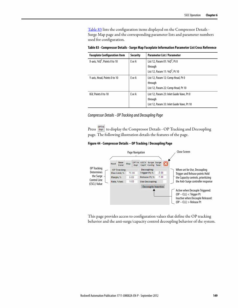
SSCC Operation Chapter 6
Table 83 lists the configuration items displayed on the Compressor Details - Surge Map page and the corresponding parameter lists and parameter numbers used for configuration.
Compressor Details - OP Tracking and Decoupling Page
Press to display the Compressor Details - OP Tracking and Decoupling page. The following illustration details the features of the page.
Figure 44 - Compressor Details – OP Tracking / Decoupling Page
This page provides access to configuration values that define the OP tracking behavior and the anti-surge/capacity control decoupling behavior of the system.
Table 83 - Compressor Details - Surge Map Faceplate Information Parameter List Cross Reference
Faceplate Configuration Item Security Parameter List / Parameter
X-axis, %Q2, Points 0 to 10 E or A List 12, Param 01: %Q2, Pt 0throughList 12, Param 11: %Q2, Pt 10
Y-axis, Head, Points 0 to 10 E or A List 12, Param 12: Comp Head, Pt 0throughList 12, Param 22: Comp Head, Pt 10
IGV, Points 0 to 10 E or A List 12, Param 23: Inlet Guide Vane, Pt 0throughList 12, Param 33: Inlet Guide Vane, Pt 10
Close Screen
When set for Use, Decoupling Trigger and Release points Hold the Capacity controls, prioritizing the Anti-Surge controller response
Active when Decouple Triggered:(OP – CLL) < Trigger PtInactive when Decouple Released:(OP – CLL) > Release Pt
Page Navigation
OP TrackingDetermines
the SurgeControl Line(CSCL) Value
Rockwell Automation Publication 1711-UM002A-EN-P - September 2012 149

Chapter 6 SSCC Operation
Table 84 lists the configuration items displayed on the Compressor Details - OP Tracking and Decoupling page and the corresponding parameter lists and parameter numbers used for configuration.
Compressor Details - Anti-Surge and Capacity Valve Page
Press to display the Compressor Details - Anti-Surge and Capacity Valve page. The following illustration details the features of the page.
Figure 45 - Compressor Details – Anti-Surge and Capacity Valve Page
This page provides access to configuration of control behaviors (control rates, control limits, and position alarms) associated with the anti-surge valve and the capacity control device (valve, IGV, etc.).
Table 84 - Compressor Details - OP Tracking/Decoupling Faceplate Information Parameter List Cross Reference
Faceplate Configuration Item Security Parameter List / Parameter
OP Tracking – Max Limit, % M, E or A List 13, Param 16: OP Track Max SP (%)
OP Tracking – Margin, % M, E or A List 13, Param 14: OP Track Margin (%)
OP Tracking – Rate, %/sec M, E or A List 13, Param 15: OP Track Rate (%/sec)
Decoupling – Trigger Pt, % M, E or A List 23, Param 02: DP1, Initiate Pt (ASC EU)
Decoupling – Release Pt, % M, E or A List 23, Param 03: DP2, Release Pt (ASC EU)
Decoupling – Use Decoupling (check box) E or A List 23, Param 01: Use Decoupling (1=Yes)
Override CV applied when compressor is:• - Not Running,• - Unloaded, or• - Comp Trip Interlock
Close Screen
Control output limited by these Min and Max values (% Open)
Position Deviation Alarm Configuration parameters
Page Navigation
Defines theOpening and
Closing rate limits
150 Rockwell Automation Publication 1711-UM002A-EN-P - September 2012

SSCC Operation Chapter 6
Table 85 lists the configuration items displayed on the Compressor Details - Anti-Surge and Capacity Valve page and the corresponding parameter lists and parameter numbers used for configuration.
Compressor Details - Surge Configuration Page
Press to display the Compressor Details - Surge Configuration page. The following illustration details the features of the page.
Figure 46 - Compressor Details – Surge Configuration Page
This page provides access to configuration values pertaining to surge detection methods (rate-of-change, and positional), multi-surge trip, and surge counters for the compressor.
Table 85 - Compressor Details – Anti-Surge and Capacity Valve Faceplate Information Parameter ListCross Reference
Faceplate Configuration Item Security Parameter List / Parameter
List 15, AntiSurge List 20, Capacity Function
Valve Slew Rate – Open, %/sec M, E or A Param 05: Param 05: OpenSlewRate (%/sec)
Valve Slew Rate – Close, %/sec M, E or A Param 06: Param 06: CloseSlewRate (%/sec)
Control Limit – CV Max, % M, E or A Param 07: Param 07: CV Max (%)
Control Limit – CV Min, % M, E or A Param 08: Param 08: CV Min (%)
Override CV (NotRun, Unload, Trip) % M, E or A Param 02: Param 02: Not Running CV (%)
Position Deviation – Pos Dev, % M, E or A Param 11: Param 10: Pos Dev Alm DB (%)
Position Deviation – Dev Time, sec M, E or A Param 12: Param 11: Pos Dev Alm Time (sec)
Total Surge Countand Counter
Reset button
Close Screen
Rate-of-Change Surge configuration parameters based on a Rate averaged over specified Time duration
Positional Surge configuration threshold and present distance from Surge (OP – SLL)
Page Navigation
Multi-Surge Trip istriggered when a
Quantity of Surgesoccur in the Time
configuredLive Rate-of-Change Value
Positional Surge configuration threshold and present distance from Surge (OP – SLL)
Rockwell Automation Publication 1711-UM002A-EN-P - September 2012 151

Chapter 6 SSCC Operation
Table 86 lists the configuration items displayed on the Compressor Details - Surge Configuration page and the corresponding parameter lists and parameter numbers used for configuration.
Compressor Details - Surge Test Page
Press to display the Compressor Details - Surge Test page. The following illustration details the features of the page.
Figure 47 - Compressor Details – Surge Test Page
This page is used during surge testing the compressor. Use this page to do the following tasks.
• Activate/deactivate surge testing• Choose the surge methods used to end the test and trap data• Examine trapped surge data• Reset trapped data
The above operations require security privilege engineer or administrator.
Table 86 - Compressor Details – Surge Configuration Faceplate Information Parameter List Cross Reference
Faceplate Configuration Item Security Parameter List / Parameter
Multi-Surge Trip – Quantity E or A List: 13, Param 08: Surge Trip Qty
Multi-Surge Trip – Time, sec E or A List: 13, Param 09: Surge Trip Time (sec)
Rate-of-Change Surge – Rate, -%.sec M, E or A List: 13, Param 10: Surge RoC Low (-%/sec)
Rate-of-Change Surge – DB, %,sec M, E or A List: 13, Param 11: Surge RoC DB (%/sec)
Rate-of-Change Surge – Time, msec M, E or A 12: Surge RoC Time (msec)
Positional Surge – Threshold M, E or A 13: Positional Srg Margin (%)
Choose whichmethods are used to
End Surge Test andTrap Surge Data
Close Screen
Compressor Data to be captured when Surge is Detected. OP and Head values plotted on the Compressor Map
Indicates if Data is Live or Trapped
Page Navigation
Surge Test Activationcontrols and status.
Automaticallydeactivates on Surge
Reset Trapped Data
152 Rockwell Automation Publication 1711-UM002A-EN-P - September 2012
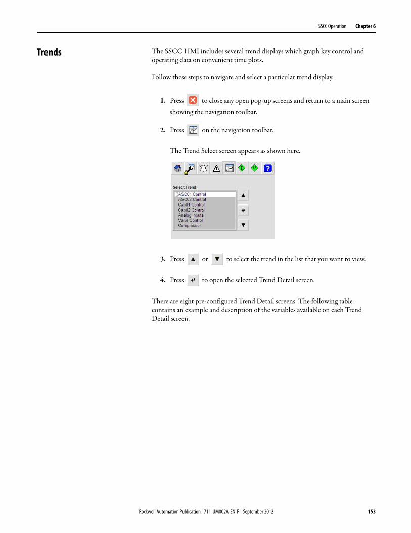
SSCC Operation Chapter 6
Trends The SSCC HMI includes several trend displays which graph key control and operating data on convenient time plots.
Follow these steps to navigate and select a particular trend display.
1. Press to close any open pop-up screens and return to a main screen showing the navigation toolbar.
2. Press on the navigation toolbar.
The Trend Select screen appears as shown here.
3. Press or to select the trend in the list that you want to view.
4. Press to open the selected Trend Detail screen.
There are eight pre-configured Trend Detail screens. The following table contains an example and description of the variables available on each Trend Detail screen.
Rockwell Automation Publication 1711-UM002A-EN-P - September 2012 153

Chapter 6 SSCC Operation
Trend Detail Description / Variables Example Screen
ASC01 Control Anti-Surge Primary PID Loop variables:
Loop PV: the calculated Operating Point value, OPLoop SP: the Surge Control Line value, SCLLoop CV: the PID output Control ValueCLL value: Control Limit Line value, represents the minimum SP for the loop
ASC02 Control Anti-Surge Secondary PID Loop variables (if configured)
Loop PV: Process Variable, as configuredLoop SP: SetpointLoop CV: The PID output Control Value
Cap01 Control Capacity Primary PID Loop variables (if configured)
Loop PV: Process Variable, as configuredLoop SP: SetpointLoop CV: The PID output Control Value
154 Rockwell Automation Publication 1711-UM002A-EN-P - September 2012

SSCC Operation Chapter 6
Cap02 Control Capacity Secondary PID Loop variables (if configured)
Loop PV: Process Variable, as configuredLoop SP: SetpointLoop CV: The PID output Control Value
Analog Inputs Pressure and Temperature signals
Discharge Pressure, PdSuction Pressure, PsDischarge Temperature, TdSuction Temperature, Ts
Trend Detail Description / Variables Example Screen
Rockwell Automation Publication 1711-UM002A-EN-P - September 2012 155

Chapter 6 SSCC Operation
Valve Control Anti-Surge and Capacity Valve signals
ASC Valve Control OutputASC Valve Position signal inputCapacity Valve/Device Control OutputCapacity Valve/Device Position signal input
Compressor Compressor values of interest
Compressor Head valueSurge Limit Line value, SLLControl Limit Line value, CLLIncipient Surge input signal (if configured)
Aux / Flow PV Auxiliary Control Signal and Compressor Flow
Auxiliary Control PV input signal (if configured)Compressor Flow input signal (as configured: Qs, Qd, Qdd, or Qalt)
Trend Detail Description / Variables Example Screen
156 Rockwell Automation Publication 1711-UM002A-EN-P - September 2012

SSCC Operation Chapter 6
Using the Trend Detail Screen
Features common to all of the Trend Detail screens are illustrated in Figure 48.
Figure 48 - Trend Details Screen
The trend plot area is configured to display four minutes of trend data. Trend data scrolls from right to left. For each pen, the trend legend identifies the variable, the pen color, and the current value. Each pen indicator’s vertical position along the right edge of the plot area follows the current value of the pen. The Y-axis scale only presents one pen scale at a time. To switch the Y-axis scale, use the next pen button to cycle through the available pens. The color of the Y-axis values follows the pen color.
The trend plot control buttons allow the user to scroll through trend data buffered by the display. The functions for each button are described here.
Button Name Function
Home Scroll trend plot back to earliest trend data in display buffer and Pause
Scroll Left Scroll trend plot back 2-minutes and Pause
Pause / Resume If trend plot is Live, then PauseIf trend plot is Paused, then resume Live updates
Scroll Right Scroll trend plot forward 2-minutes and Pause
End Scroll trend plot forward to most recent trend data and Resume Live update
X-Axis, time scale
Current Day, Date
Trend Legend:• From 1 to 4 Pens• Pen colors• Pen values
Cycles the Y-Axis display scale for each Pen
Y-Axis Scale:• Based on Pen EU scale• Use “Next Pen” to
cycle through Pens• Color matches Pen
Pen Indicators
Trend Detail Screen Name
Trend Plot control buttons
Trend Plot Area
Rockwell Automation Publication 1711-UM002A-EN-P - September 2012 157

Chapter 6 SSCC Operation
Trend Technical Specifications
Trend Plot area:
X-Axis, Time scale 4-minutes (fixed)
Y-Axis Pre-configured to EU range of Pen(s)
Trend Sampling 1-second
Trend History
Trend Log 240 samples (4-minutes) available on Trend Open
Display Buffer 4800 samples (80-minutes) while screen open.Clears when screen closed.
158 Rockwell Automation Publication 1711-UM002A-EN-P - September 2012

Chapter 7
Modbus Interface
The SSCC has a RS-232 serial port for Modbus communication. The port is located on the front of the controller. The protocol supported is RTU in slave mode.
Serial Port Configuration The following table shows the parameters related to Modbus communication.
Configuration of the Modbus interface is performed through the HMI. Refer to configuration details for parameter list 29: Modbus Serial Port Configuration on page 87.
Figure 49 - Modbus Serial Port Configuration Screen
Table 87 - Modbus Communication Parameters
Parameter Description Range
1 Slave ID 1…254
2 Register Scaling Range 0…32767
3 Baud Rate Configuration 0…38400
4 Parity Configuration (0=None, 1=Odd, 2=Even) 0…2
5 Baud Rate Read back 0…38400
6 Parity Read back 0…2
7 Set Port Config (1=Set Port Config) 0…1
Rockwell Automation Publication 1711-UM002A-EN-P - September 2012 159

Chapter 7 Modbus Interface
Modbus Holding Registers Modbus data access to the SSCC utilizes only Modbus holding registers. Modbus function code 3 can be used to read these registers.
The map of Modbus registers is presented in the following table. Where indicated, the SSCC EU (engineering unit) value range is converted to the Modbus register range configured in parameter 2.
Table 88 - Modbus Holding Register Assignments
Address Data Type EU Range Service
40001 INT 0.0 to 100.0 ASC Primary PID Loop – Process Value (Operating Point, OP)
40002 INT 0.0 to 100.0 ASC Primary PID Loop – Setpoint in Use
40003 INT 0.0 to 100.0 ASC Primary PID Loop – Control Value
40004 INT EU Min to EU Max Compressor Flow input signal
40005 INT EU Min to EU Max Suction Pressure input signal
40006 INT EU Min to EU Max Suction Temperature input signal
40007 INT EU Min to EU Max Discharge Pressure input signal
40008 INT EU Min to EU Max Discharge Temperature input signal
40009 INT 0.0 to 100.0 Incipient Surge input signal
40010 INT 0.0 to 100.0 ASC Valve Position input signal
40011 INT 0.0 to 100.0 CAP Valve/IGV Position input signal
40012 INT 0.0 to 10.0 Compressor Head (HpSim or Pratio)
40013 INT 0.0 to 100.0 Surge Limit Line, SLL
40014 INT 0.0 to 100.0 Control Limit Line, CLL
40015 INT 0.0 to 100.0 Surge Control Line, SCLASC Primary PID Loop - Setpoint
40016 INT 0.0 to 100.0 Surge Map X-Axis, Pt-0
40017 INT 0.0 to 100.0 Surge Map X-Axis, Pt-1
40018 INT 0.0 to 100.0 Surge Map X-Axis, Pt-2
40019 INT 0.0 to 100.0 Surge Map X-Axis, Pt-3
40020 INT 0.0 to 100.0 Surge Map X-Axis, Pt-4
40021 INT 0.0 to 100.0 Surge Map X-Axis, Pt-5
40022 INT 0.0 to 100.0 Surge Map X-Axis, Pt-6
40023 INT 0.0 to 100.0 Surge Map X-Axis, Pt-7
40024 INT 0.0 to 100.0 Surge Map X-Axis, Pt-8
40025 INT 0.0 to 100.0 Surge Map X-Axis, Pt-9
40026 INT 0.0 to 100.0 Surge Map X-Axis, Pt-10
40027 INT 0.0 to 10.0 Surge Map Y-Axis, Pt-0
40028 INT 0.0 to 10.0 Surge Map Y-Axis, Pt-1
40029 INT 0.0 to 10.0 Surge Map Y-Axis, Pt-2
40030 INT 0.0 to 10.0 Surge Map Y-Axis, Pt-3
40031 INT 0.0 to 10.0 Surge Map Y-Axis, Pt-4
40032 INT 0.0 to 10.0 Surge Map Y-Axis, Pt-5
40033 INT 0.0 to 10.0 Surge Map Y-Axis, Pt-6
160 Rockwell Automation Publication 1711-UM002A-EN-P - September 2012

Modbus Interface Chapter 7
40034 INT 0.0 to 10.0 Surge Map Y-Axis, Pt-7
40035 INT 0.0 to 10.0 Surge Map Y-Axis, Pt-8
40036 INT 0.0 to 10.0 Surge Map Y-Axis, Pt-9
40037 INT 0.0 to 10.0 Surge Map Y-Axis, Pt-10
40038 INT EU Min to EU Max ASC Secondary PID Loop – Process Value
40039 INT EU Min to EU Max ASC Secondary PID Loop – Setpoint Target
40040 INT EU Min to EU Max ASC Secondary PID Loop – Setpoint in Use
40041 INT 0.0 to 100.0 ASC Secondary PID Loop – Control Value
40042 INT EU Min to EU Max Capacity Primary PID Loop – Process Value
40043 INT EU Min to EU Max Capacity Primary PID Loop – Setpoint Target
40044 INT EU Min to EU Max Capacity Primary PID Loop – Setpoint in Use
40045 INT 0.0 to 100.0 Capacity Primary PID Loop – Control Value
40046 INT EU Min to EU Max Capacity Secondary PID Loop – Process Value
40047 INT EU Min to EU Max Capacity Secondary PID Loop – Setpoint Target
40048 INT EU Min to EU Max Capacity Secondary PID Loop – Setpoint in Use
40049 INT 0.0 to 100.0 Capacity Secondary PID Loop – Control Value
40050 INT 0.0 to 100.0 Capacity Valve/IGV Control Output
40051 INT 0.0 to 100.0 Total Margin in Use
40052 INT No scaling Surge Counter
40053 INT 0.0 to 100.0 Reserved for future use
40054 INT 0.0 to 100.0 Reserved for future use
40055 INT 0.0 to 100.0 Reserved for future use
40056 INT 0.0 to 100.0 Reserved for future use
40057 INT 0.0 to 100.0 Reserved for future use
40059 INT 0.0 to 100.0 Reserved for future use
40060 INT 0.0 to 100.0 Reserved for future use
Table 88 - Modbus Holding Register Assignments (Continued)
Address Data Type EU Range Service
Rockwell Automation Publication 1711-UM002A-EN-P - September 2012 161

Chapter 7 Modbus Interface
Notes:
162 Rockwell Automation Publication 1711-UM002A-EN-P - September 2012
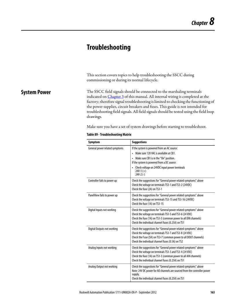
Chapter 8
Troubleshooting
This section covers topics to help troubleshooting the SSCC during commissioning or during its normal lifecycle.
System Power The SSCC field signals should be connected to the marshaling terminals indicated on Chapter 3 of this manual. All internal wiring is completed at the factory; therefore signal troubleshooting is limited to checking the functioning of the power supplies, circuit breakers and fuses. This guide is not intended for troubleshooting field signals. All field signals should be tested using the field loop drawings.
Make sure you have a set of system drawings before starting to troubleshoot.
Table 89 - Troubleshooting Matrix
Symptom Suggestions
General power related symptoms If the system is powered from an AC source:• Make sure 120 VAC is available at CB1.• Make sure CB1 is in the “On” position.If the system is powered from a DC source: • Check voltage on 24VDC input power terminals
24V-1 (+)24V-2 (-)
Controller fails to power up Check the suggestions for “General power related symptoms” aboveCheck the voltage on terminals TS3-1 and TS3-2 (24VDC)Check the fuse (2A) on TS3-1
PanelView fails to power up Check the suggestions for “General power related symptoms” aboveCheck the voltage on terminals TS3-15 and TS3-16 (24VDC)Check the fuse (1A) on TS3-15
Digital Inputs not working Check the suggestions for “General power related symptoms” aboveCheck the voltage on terminals TS3-5 and TS3-6 (24 VDC)Check the fuse (1A) on TS3-5 (common power to all DIN channels)Check the individual channel fuses (0.25A) on TS1
Digital Outputs not working Check the suggestions for “General power related symptoms” aboveCheck the voltage on terminals TS3-7 and TS3-8 (24 VDC)Check the f use (5A) on TS3-7 (common power to all DOUT channels)Check the individual channel fuses (0.5A) on TS2
Analog Inputs not working Check the suggestions for “General power related symptoms” aboveCheck the voltage on terminals TS3-3 and TS3-4 (24 VDC)Check the fuse (1A) on TS3-3 (common power to all AIN channels)Check the individual channel fuses (0.25A) on TS1
Analog Output not working Check the suggestions for “General power related symptoms” aboveNote: 24V DC power for AO channels are sourced from the controller power supply.Check the individual channel fuses (0.25A) on TS1
Rockwell Automation Publication 1711-UM002A-EN-P - September 2012 163

Chapter 8 Troubleshooting
Hardware Status The Hardware screen on the HMI provides detailed status of the controller, I/O modules, I/O channels, and access to the HMI configuration (exit graphics).
The Hardware screen has three pages to support troubleshooting/maintenance activities the SSCC hardware. When the Hardware screen opens, the last viewed page is presented to the user.
Table 90 - Hardware Screen Pages
Page Screen Examples Description
1 Hardware Screen – Controller Status Display Features:• Controller status indications: Mode, Controller, Battery, I/O System, Minor Faults, Major Faults and
Ethernet.• Memory usage statistics.Operational Features:
• Use or to check the status of the individual modules.
• Press to open a Module Detail popup for the chosen I/O module.
2 Hardware Screen – Major / Minor Faults Display Features:• Detailed major fault and minor fault status.Operational Features:
• Press to reset major and minor faults - security privilege required (O, S, M, E, or A).
3 Hardware Screen – PanelView Plus MaintenanceOperational Features:
Press to exit the HMI graphics and access the PanelView Plus device configuration - security privilege required (E, or A).
Press to set the controller clock time to the PanelView clock time - security privilege required (E, or A).
164 Rockwell Automation Publication 1711-UM002A-EN-P - September 2012

Troubleshooting Chapter 8
Follow these steps to access the Hardware screen.
1. Press to close any open pop-up screens and return to a main screen showing the navigation toolbar.
2. Press on the navigation toolbar.
The Maintenance screen appears.
3. Press to page forward, or to page backward, as required to navigate to page one of the Maintenance screen, page 1, Configuration and Settings (shown here).
4. Press to open the Hardware screen - Controller Status (page 1).
Controller Status
The Controller Status page provides details on the controller and a selector to access individual I/O module details.
Figure 50 - Hardware Screen, Page 1 - Controller Status
A variety of status information is presented adjacent to the controller graphic image on the Controller Status page. These indications are detailed in the following tables.
Rockwell Automation Publication 1711-UM002A-EN-P - September 2012 165

Chapter 8 Troubleshooting
Table 91 - Application Mode Status
Indication Description
The application is in Run mode. This is the normal operating mode for the system.
The application is in Program mode.Use the key on the front of the controller to switch to Run mode.
The application is in Test mode.Use the key on the front of the controller to switch to Run mode.
Table 92 - Controller Status
Indication Description
The controller is healthy.This is the normal operating mode for the system.
The controller status is faulted.A critical fault has occurred on the controller and it is not in operation.Search for additional details under the major faults.
Table 93 - Battery Status
Indication Description
The controller battery is OK.This is the normal indication for the system.
The controller batter is low and should be replaced.
Table 94 - I/O System Status
Indication Description
All the I/O modules are running.This is the normal indication for the system
(flashing green)
At least one I/O module is not running.Check individual module status on the I/O Module Selector to identify a particular module. Search additional details for individual I/O modules.
(flashing red)
None of the I/O modules are running.Check the levers on the top of each Compact I/O module and I/O end cap. They should all be properly positioned to left, to engage the connection to each other and the controller.Restart the system. If the problem persists contact Rockwell Automation for assistance.
There are no I/O modules configured in the system.This indication is not expected to appear, as the system is pre-configured for I/O connections. Contact Rockwell Automation for assistance.
166 Rockwell Automation Publication 1711-UM002A-EN-P - September 2012

Troubleshooting Chapter 8
Controller Major and Minor Fault Status
Additional details about major and minor fault status for the controller is available on page 2 of the Hardware Status screen.
Figure 51 - Hardware Screen, Page 2 - Major and Minor Faults
The reset button on this screen can be used to reset controller faults. This will normally pertain to minor faults. In case of major faults, it is often necessary to restart the controller.
Table 95 - Minor Fault Status
Indication Description
There are no minor faults reported for the controller.This is the normal indication for the system.
There is at least one minor fault reported for the controller.Navigate to Hardware Status page 2 for further details on minor faults.Minor faults are recoverable, and can be reset on page 2. If the fault persists contact Rockwell Automation for assistance.
Table 96 - Major Fault Status
Indication Description
There are no major faults reported for the controller.This is the normal indication for the system.
There has been a major fault reported for the controller, and the controller has been stopped.Some major faults are recoverable. You can restart the system and observe if the fault is cleared or persists. If the fault persists contact Rockwell Automation for assistance.
Table 97 - Ethernet Status
Indication Description
The onboard Ethernet interface is operating normally.This is the normal indication for the system.
A fault is reported for the onboard Ethernet interface.Restart the system. If the problem persists contact Rockwell Automation for assistance.
Rockwell Automation Publication 1711-UM002A-EN-P - September 2012 167

Chapter 8 Troubleshooting
The Reset button requires security privileges (operator, supervisor, maintenance, engineer, or administrator).
PanelView Maintenance
The PanelView Plus Maintenance page is shown in Figure 52.
Figure 52 - Hardware Screen, Page 3 - PanelView Plus Maintenance
This page contains the following icons.
I/O Modules I/O Module Detail screens facilitate installation and commissioning activities, and system troubleshooting. Follow these steps to access the desired I/O Module Detail screen.
1. Press to close any open pop-up screens and return to a main screen showing the navigation toolbar.
2. Press on the navigation toolbar.
The Maintenance screen appears.
Icon Action
Exits the HMI graphics, and accesses the PanelView Plus configuration and maintenance features (network settings, file management, screen saver, and PanelView date/time).Consult the PanelView Plus product documentation for details.
Sets the clock in the controller using the present clock settings on the PanelView.
168 Rockwell Automation Publication 1711-UM002A-EN-P - September 2012

Troubleshooting Chapter 8
3. Press to page forward, or to page backward, as required to navigate to page one of the Maintenance screen, page 1, Configuration and Settings (shown here).
4. Press to open the Hardware screen - Controller Status (page 1).
5. Press to page forward, or to page backward, as required to navigate to page one of the Hardware screen, page-1 – Controller Status (shown here).
6. Press to select the desired module from the I/O Module selector
list at the bottom of the screen. The following I/O modules are available.• For Digital Inputs: Slot 1: 1769-IQ16• For Digital Outputs: Slot 2: 1769-OB16• For Analog Inputs: Slot 3: 1769-IF8• For Analog Outputs: Slot 4: 1769-OF4
7. Press to open the IO Module Detail page (for example: Analog Inputs).
Rockwell Automation Publication 1711-UM002A-EN-P - September 2012 169

Chapter 8 Troubleshooting
Digital Input Module Detail
The Digital Input Module Detail screen is shown in Figure 53.
Figure 53 - Digital Input Module Detail
For each input channel, the channel number and description are presented. The channel descriptions on this screen are fixed and cannot be customized. They reflect the allocated function for each channel. The channel number is used as a status indicator for the individual channel.
Digital Output Module Detail
The Digital Output Module Detail screen is shown in Figure 54.
Figure 54 - Digital Output Module Detail
For each output channel, the channel number and description are presented. The channel descriptions on this screen are fixed and cannot be customized. They
Visual Indication Example Explanation
The green color indicates the input is energized, logic 1.
The grey color indicates the input is de-energized, logic 0.
The red color indicates a fault is reported.
170 Rockwell Automation Publication 1711-UM002A-EN-P - September 2012
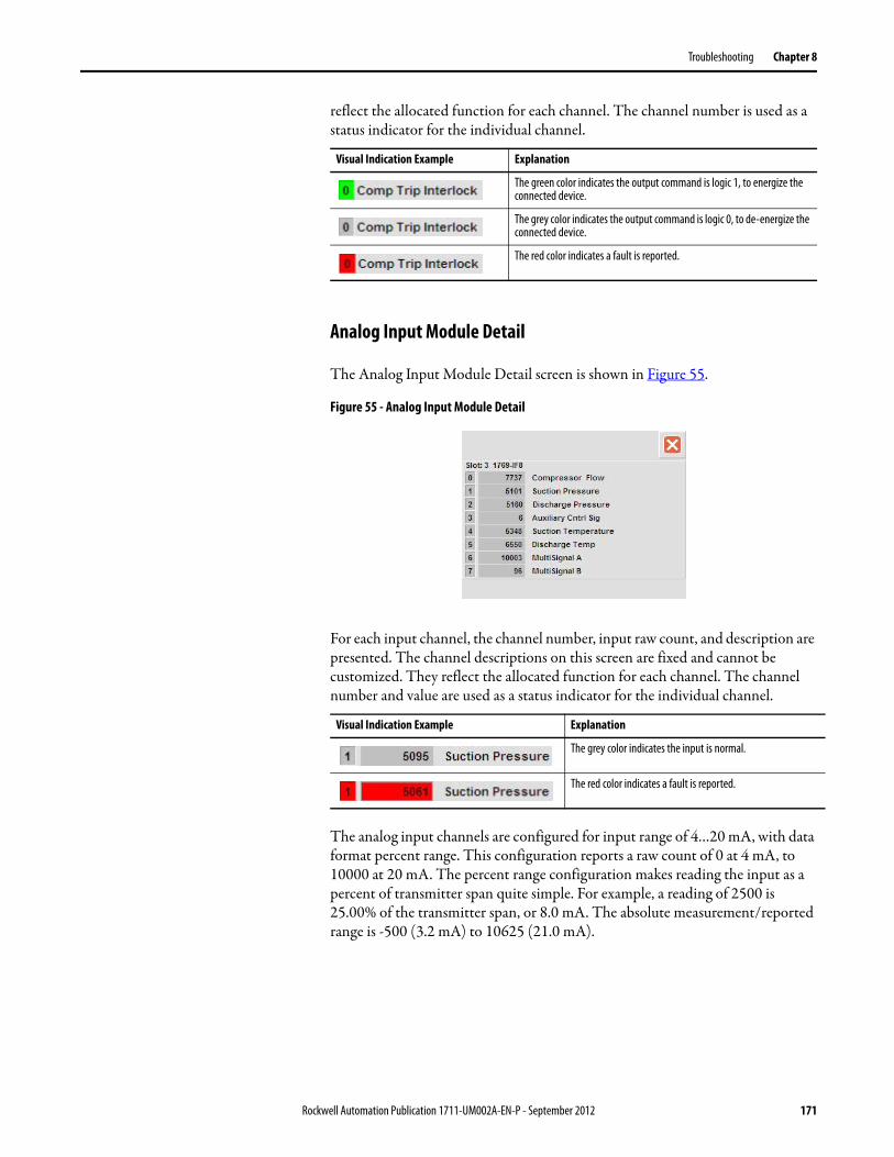
Troubleshooting Chapter 8
reflect the allocated function for each channel. The channel number is used as a status indicator for the individual channel.
Analog Input Module Detail
The Analog Input Module Detail screen is shown in Figure 55.
Figure 55 - Analog Input Module Detail
For each input channel, the channel number, input raw count, and description are presented. The channel descriptions on this screen are fixed and cannot be customized. They reflect the allocated function for each channel. The channel number and value are used as a status indicator for the individual channel.
The analog input channels are configured for input range of 4…20 mA, with data format percent range. This configuration reports a raw count of 0 at 4 mA, to 10000 at 20 mA. The percent range configuration makes reading the input as a percent of transmitter span quite simple. For example, a reading of 2500 is 25.00% of the transmitter span, or 8.0 mA. The absolute measurement/reported range is -500 (3.2 mA) to 10625 (21.0 mA).
Visual Indication Example Explanation
The green color indicates the output command is logic 1, to energize the connected device.
The grey color indicates the output command is logic 0, to de-energize the connected device.
The red color indicates a fault is reported.
Visual Indication Example Explanation
The grey color indicates the input is normal.
The red color indicates a fault is reported.
Rockwell Automation Publication 1711-UM002A-EN-P - September 2012 171

Chapter 8 Troubleshooting
Analog Output Module Detail
The Analog Output Module Detail screen is shown in Figure 56.
Figure 56 - Analog Output Module Detail
For each output channel, the channel number, output command value, and description are presented. The channel descriptions on this screen are fixed and cannot be customized. They reflect the allocated function for each channel. The channel number and value are used as a status indicator for the individual channel.
The analog output channels are configured for output range of 4…20 mA, with data format percent range. This configuration generates the 4…20 mA output from a command range of 0 to 10000 counts. The percent range configuration makes reading the output command as a percentage, e.g. a command of 7500 is 75.00% to the control device, or 16.0 mA.
Alarms The overall unit Alarm status is presented on the Alarms button (third from the left) displayed on the Navigation Toolbar of any main screen.
The alarm status is represented by the bell color and its steady or flashing status as explained in Table 98 on page 173.
Visual Indication Example Explanation
The grey color indicates the output is normal.
The red color indicates a fault is reported.
172 Rockwell Automation Publication 1711-UM002A-EN-P - September 2012

Troubleshooting Chapter 8
To check the status of the Alarms, press the Alarms button on the toolbar to open the Alarms screen.
Managing Alarms
The SSCC alarms are managed from a single Alarm screen. The features of the Alarm screen are shown in the following figure.
Figure 57 - Alarm Screen Components
Table 98 - Unit Alarm Summary Icon Indications
Alarm Icon
Alarm Severity Bell Color - Status Explanation
4: FaultHardware faults, Xmtr faults
Pink - steady Active alarm present, check Alarm screen for details
Pink - flashing Alarm cleared, reset alarm on Alarm screen
3: ExceptionCompressor Trip conditions
Red - steady Active alarm present, check Alarm screen for details
Red - flashing Alarm cleared, reset alarm on Alarm screen
2: AlertHi / Lo Alarms,Control Fallback Strategies
Yellow - steady Active alarm present, check Alarm screen for details
Yellow - flashing Alarm cleared, reset alarm on Alarm screen
1: InformationSurge Testing
Blue - steady Active alarm present, check Alarm screen for details
Blue - flashing Alarm cleared, reset alarm on Alarm screen
None White - solid No active alarms, no alarms require reset
Alarm Select Indicator
Move Alarm Selector:Page Up
Scroll UpScroll DownPage Down
Alarm ResetAcknowledge All AlarmsAcknowledge Selected Alarm
Alarm List
Rockwell Automation Publication 1711-UM002A-EN-P - September 2012 173

Chapter 8 Troubleshooting
Within the alarm list, the individual alarm message status is graphically represented based on the alarm state (active or inactive) and acknowledgement (Ack’d or not-Ack’d).
All the alarms defined in the SSCC are listed in the next table. The table is sorted alphabetically by alarm message.
Alarm State Acknowledgement Alarm Message Representation
Active Not Acknowledged Severity Color – Flashing
Active Acknowledged Severity Color – Steady
Inactive Not Acknowledged Dark Grey – Flashing
Inactive Acknowledged Light Grey – Steady (historical)
Table 99 - Alarm Messages
Alarm Message Severity Explanation of Condition
Analog Input Module Failure Fault (4) Fault reported for analog input module in Slot 3
Analog Output Module Failure Fault (4) Fault reported for analog output module in Slot 4
AntiSurge Valve Position Error Alert (2) Deviation between control signal and position feedback > deviation limit and duration.
Aux Control Signal Overrange Fault (4) Transmitter signal > 20.4 mA(Analog input raw count > 10250)
Aux Control Signal Underrange Fault (4) Transmitter signal < 3.6 mA(Analog input raw count < -250)
Auxiliary Control Signal High Alert (2) Auxiliary control signal > high alarm limit
Auxiliary Control Signal Low Alert (2) Auxiliary control signal < low alarm limit
Capacity Valve Position Error Alert (2) Deviation between control signal and position feedback > deviation limit and duration
Comm Interface Failure Fault (4) Fault reported for the Ethernet communication interface
Compressor Flow High Alert (2) Compressor flow > high alarm limit
Compressor Flow Low Alert (2) Compressor flow < low alarm limit
Compressor Flow Overrange Fault (4) Transmitter signal > 20.4 mA(Analog input raw count > 10250)
Compressor Flow Underrange Fault (4) Transmitter signal < 3.6 mA(Analog input raw count < -250)
Compressor Head Fault Alert (2) Conditions exist (i.e. transmitter faults) that prevent calculation of compressor head. As a result:Head values are set to default values (HpSim = 0.0, Pratio = 1.0, Prise = 0.0). This condition will trigger the minimum flow fallback.
Compressor Surge Detected Alert (2) Compressor surge detected by either:Positional surge: Operating point (OP) is below the surge limit line (SLL) value by more than the positional surge margin.
Rate-of-change: The operating point decreased at a rate exceeding the configured rate-of-change limits.
As a result, the offset and/or percent margin in use are automatically increased.
Controller Failure Fault (4) Fault reported for the controller
Digital Input Module Failure Fault (4) Fault reported for digital input module in Slot 1
174 Rockwell Automation Publication 1711-UM002A-EN-P - September 2012

Troubleshooting Chapter 8
Digital Output Module Failure Fault (4) Fault reported for digital output module in Slot 2
Discharge Press Overrange Fault (4) Transmitter signal > 20.4 mA(Analog input raw count > 10250)
Discharge Press Underrange Fault (4) Transmitter signal < 3.6 mA(Analog input raw count < -250)
Discharge Pressure High Alert (2) Discharge pressure > high alarm limit
Discharge Pressure Low Alert (2) Discharge pressure < low alarm limit
Discharge Temp Overrange Fault (4) Transmitter signal > 20.4 mA(Analog input raw count > 10250)
Discharge Temp Underrange Fault (4) Transmitter signal < 3.6 mA(Analog input raw count < -250)
Discharge Temperature High Alert (2) Discharge temperature > high alarm limit
Discharge Temperature Low Alert (2) Discharge temperature < low alarm limit
External Trip 1 Exception (3)
The external compressor trip signal connected to DIN channel 12 is in the “Tripped” condition.
As a result, a compressor trip is generated.
External Trip 2 Exception (3)
The external compressor trip signal connected to DIN channel 13 is in the “Tripped” condition.
As a result, a compressor trip is generated.
External Trip 3 Exception (3)
The external compressor trip signal connected to DIN channel 14 is in the “Tripped” condition.
As a result, a compressor trip is generated.
External Trip 4 Exception (3)
The external compressor trip signal connected to DIN channel 15 is in the “Tripped” condition.
As a result, a compressor trip is generated.
Incipient Surge Alert (2) Incipient surge signal > high alarm limit
Minimum Flow Fallback Alert (2) Triggered by Compressor Head Fault.
Without a calculated head, the surge limit line (SLL) value cannot be determined by normal lookup table.
In this condition, the SLL value is set to the largest OP value defined for the surge map, to assure a minimum safe flow through the compressor.
Minimum IGV Fallback Alert (2) Triggered by an inlet guide vane (IGV) position signal failure.
As a result, IGV methods for the surge limit line fallback to using the most conservative IGV position - full open.
Multi-Use Signal A Overrange Fault (4) Transmitter signal > 20.4 mA(Analog input raw count > 10250)
Multi-Use Signal A Underrange Fault (4) Transmitter signal < 3.6 mA(Analog input raw count < -250)
Multi-Use Signal B Overrange Fault (4) Transmitter signal > 20.4 mA(Analog input raw count > 10250)
Multi-Use Signal B Underrange Fault (4) Transmitter signal < 3.6 mA(Analog input raw count < -250)
Table 99 - Alarm Messages (Continued)
Alarm Message Severity Explanation of Condition
Rockwell Automation Publication 1711-UM002A-EN-P - September 2012 175

Chapter 8 Troubleshooting
Multiple Surge Trip Exception (3)
Multiple surges have occurred within a configured time period.As a result, a compressor trip is generated.
Operating Point (OP) Fault Exception (3)
Conditions exist (i.e. transmitter fault or configuration errors) that prevent calculation of the operating point.As a result, a compressor trip is generated.
Suction Press Overrange Fault (4) Transmitter signal > 20.4 mA(Analog input raw count > 10250)
Suction Press Underrange Fault (4) Transmitter signal < 3.6 mA(Analog input raw count < -250)
Suction Pressure High Alert (2) Suction pressure > high alarm limit
Suction Pressure Low Alert (2) Suction pressure < low alarm limit
Suction Temp Overrange Fault (4) Transmitter signal > 20.4 mA(Analog input raw count > 10250)
Suction Temp Underrange Fault (4) Transmitter signal < 3.6 mA(Analog input raw count < -250)
Suction Temperature High Alert (2) Suction temperature > high alarm limit
Suction Temperature Low Alert (2) Suction temperature < low alarm limit
Surge Test Enabled Information (1)
Surge test is enabled, which bypasses the Manual mode protection for the anti-surge primary PID loop.
Table 99 - Alarm Messages (Continued)
Alarm Message Severity Explanation of Condition
176 Rockwell Automation Publication 1711-UM002A-EN-P - September 2012
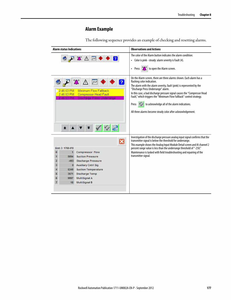
Troubleshooting Chapter 8
Alarm Example
The following sequence provides an example of checking and resetting alarms.
Alarm status Indications Observations and Actions
The color of the Alarm button indicates the alarm condition:• Color is pink - steady: alarm severity is Fault (4).
• Press to open the Alarm screen.
On the Alarm screen, there are three alarms shown. Each alarm has a flashing color indication.The alarm with the alarm severity, fault (pink) is represented by the “Discharge Press Underrange” alarm.In this case, a bad discharge pressure signal causes the “Compressor Head Fault,” which triggers the “Minimum Flow Fallback” control strategy.
Press to acknowledge all of the alarm indications.
All three alarms become steady color after acknowledgement.
Investigation of the discharge pressure analog input signal confirms that the transmitter signal is below the threshold for underrange.This example shows the Analog Input Module Detail screen and AI channel 2 percent range value is less than the underrange threshold of “-250.”Maintenance is tasked with field troubleshooting and repairing of the transmitter signal.
Rockwell Automation Publication 1711-UM002A-EN-P - September 2012 177

Chapter 8 Troubleshooting
Maintenance determines the field transmitter is bad and replaces it. The analog input signal is back in normal range.
Returning to the Alarm screen, two of the alarms have cleared:• The underrange cleared with the successful transmitter replacement.
With the discharge pressure signal healthy, the compressor head calculation fault has also cleared.
• The “Minimum Flow Fallback” is still presented as an active alarm, as the system is still using this fallback strategy.
The Alarm button is flashing pink, indicating the alarm severity (Fault-4) is cleared and can be reset.
Press . This resets the alarm status, and also resets the “Minimum
Flow Fallback” condition, returning the anti-surge control strategy to normal.All the alarm conditions are clear on the alarm list.The Alarm button color is white (no alarms).
Alarm status Indications Observations and Actions
178 Rockwell Automation Publication 1711-UM002A-EN-P - September 2012

Troubleshooting Chapter 8
Configuration Errors The SSCC has built in a basic configuration error routine. When a configuration error is detected, a warning is generated. Configuration errors should be cleared before running the compressor.
Table 100 - Configuration Errors
Configuration Error Check the following
Head Calc Config Error One or more of the following configuration properties must be corrected:Suction Pressure AIN configured for Use, Ref List-2, Param-1Discharge Pressure AIN configured for Use, Ref: List-3, Param-1Gas ratio of Specific Heats (1.0 < value < 2.0), Ref List-11, Param-3Polytropic Efficiency (0.0 < value < 1.0), Ref List-11, Param-4If Variable Polytropic exponent is configured (Ref: List-11, Param-9) then:
Suction Temperature AIN configured for Use, Ref: List-5, Param-1Discharge Temperature AIN configured for Use, Ref: List-6, Param-1
OP Calc Config Error One or more of the following configuration properties must be corrected:Flow AIN configured for Use (value = 1, 2, 3, or 4), Ref: List-1, Param-1Maximum Flow range normalization (Qmax > 0.0), Ref: List-11, Param-7Base Pressure of Compressor (Pbc > 0.0), Ref: List-11, Param-2Base Temp of Compressor (Tbc > 0.0), Ref: List-11, Param-1Base Pressure of Flow Measurement (Pbo > 0.0), Ref List-11, Param-6Base Temp of Flow Measurement (Tbo > 0.0), Ref List-11, Param-5
Surge Map Config Error One or more of the following configuration properties must be corrected:Surge Map X-axis Normalized Flow values, %Q2 must be ascending:Pt-0 <= Pt-1, Pt-1 <= Pt-2,…Pt-8 <= Pt-9, Pt-9 < Pt-10Ref: List-12, Param-1 to 11Surge Map Y-axis Compressor Head values must be ascending:Pt-0 <= Pt-1, Pt-1 <= Pt-2,…Pt-8 <= Pt-9, Pt-9 < Pt-10Ref: List-12, Param-12 to 22If Inlet Guide Vane Method is configured (Ref: List-11, Param-12) then:
Surge Map IGV values must be ascending:Pt-0 <= Pt-1, Pt-1 <= Pt-2,…Pt-8 <= Pt-9, Pt-9 < Pt-10Ref: List-12, Param-23 to 33
Rockwell Automation Publication 1711-UM002A-EN-P - September 2012 179

Chapter 8 Troubleshooting
Startup or Operating Issues This section covers some of the issues that can be found during the compressor startup or operation process and the suggested actions for correcting the issue.
Table 101 - Compressor Startup/Operation Symptoms and Suggested Action(s)
Symptom Suggested Action(s)
Compressor will not start Check the interlocks used to generate the compressor trip output signal.Investigate any “Trip” conditions, they must be cleared or bypassed to start.Reset the latched Interlocks using “Interlock reset”.Check the Compressor Trip Digital Output Device faceplate - should be in Program mode.Check the permissives used to generate a “Ready to Start” output signal.Investigate any “Not Ready” conditions - they must be ready or bypassed to start.Check the Ready To Start Digital Output Device faceplate - should be in Program mode.
Compressor is running, but run is not indicated on the Compressor Overview screen
Check methods for run determination:Compressor Run Digital Input:• Check the input signal on DIN channel-0.• Check the channel fuse.• Check that the digital input channel is configured for use.• Check the device faceplate if the input is in Substitute PV mode.
Compressor head used for run determination:• Check for: Compressor Head > Head Run Threshold• Check for a “Compressor Head Calc” fault .
Auxiliary control PV used for run determination (i.e. Amps):• Check for: Aux Control PV > Aux Run Threshold• Check if the Aux Control Device faceplate if input is in Substitute PV mode.
Check the on-delay timer preset for run determination.
Compressor will not load Check method for load request.
External load push button:• Check the input signal on DIN channel-2.• Check the channel fuse.
The Load button is located on the HMI Operator screen - security privilege is required.
Digital input signal is wired to controller, but functionality does not work
Check the wiring for the input on TS1.Check the fuse for the input on TS1.Check that the DI status reports correctly on the IO screen for the digital input module.Check that the DI channel is configured for use.Check that the input state for the channel is configured correctly.Open the device faceplate, check if device in Substitute PV mode.
Analog input signal is wired to controller, but functionality does not work
Check the wiring for the input on TS1. Verify that the polarity is correct.Check the fuse for the input on TS1.Check the analog input reading on the IO screen for the analog input module. Raw counts read 0 at 4 mA, and 10000 at 20 mA.Check that the AI channel is configured for use.Check that the engineering unit range and scaling is configured correctly.Open the device faceplate, check if device in Substitute PV mode.
180 Rockwell Automation Publication 1711-UM002A-EN-P - September 2012

Index
AAC safety ground 16access
Device faceplate 128Hardware screen 165I/O Module Detail screen 168Interlocks Configuration screen 93Parameter Configuration screen 89parameter list 89Permissives Configuration screen 93Trend displays 153
activatehuman machine interface 25
activation key ID 25adaptive tuning
definition 143features 11
Adaptive Tuning Configuration page 142alarm icon
status indications 173alarm message 176
analog input module failure 174analog output module failure 174antisurge valve position error 174aux control signal overrange 174aux control signal underrange 174auxiliary control signal high 174auxiliary control signal low 174capacity valve position error 174comm interface failure 174compressor flow high 174compressor flow low 174compressor flow overrange 174compressor flow underrange 174compressor head fault 174compressor surge detected 174controller failure 174digital input module failure 174digital output module failure 175discharge press overrange 175discharge press underrange 175discharge pressure high 175discharge pressure low 175discharge temp overrange 175discharge temp underrange 175discharge temperature high 175discharge temperature low 175external trip 1 175external trip 2 175external trip 3 175external trip 4 175incipient surge 175minimum flow fallback 175minimum IGV fallback 175multiple surge trip 176multi-use signal A overrange 175multi-use signal A underrange 175multi-use signal B overrange 175multi-use signal B underrange 175operating point (OP) fault 176suction press overrange 176suction press underrange 176
suction pressure high 176suction pressure low 176suction temp overrange 176suction temp underrange 176suction temperature high 176suction temperature low 176surge test enabled 176
Alarm screendescription 33security privileges 43
alarmsmanage 173reset 177view 177
analog inputchannel assignment 22channel status 171configure 133operation 132processing 10PV from input mode 132substitute PV mode 132
Analog Input Device faceplate 132Analog Input Device screen
security privileges 45analog input in substitute PV mode
warning 117Analog Input Module Detail screen 171analog input module failure
alarm message 174analog input signal is wired to controller, but
functionality does not work 180analog inputs not working
troubleshoot 163analog inputs ok
permissive 113analog output
channel assignment 23channel status 172configure 135operation 134processing 11
Analog Output Device faceplate 134Analog Output Device screen
security privileges 45Analog Output Module Detail screen 172analog output module failure
alarm message 174analog output not working
troubleshoot 163analog outputs ok
permissive 113anti-surge control
block diagram 10calculated values 101Compressor Overview page 97features 11PID loop 141signal status 101view PID loops 104
anti-surge mode protection 142
Rockwell Automation Publication 1711-UM002A-EN-P - September 2012 181

Index
antisurge valve position erroralarm message 174
antisurge vlv readypermissive 113
application mode status 166aux control signal overrange
alarm message 174aux control signal underrange
alarm message 174auxiliary control signal high
alarm message 174auxiliary control signal low
alarm message 174
Bbattery status
controller 166buttons
toolbar 29
Ccapacity control
discharge throttling 100inlet guide vanes 99PID loop 106, 141signal status 101speed setpoint to speed controller 100suction throttling 99
capacity decouplingfeatures 11
capacity valve position erroralarm message 174
capacity/IGV readypermissive 113
changepassword 41
clockset (HMI) 168
comm interface failurealarm message 174
communications interfaceModbus 159
compact flash card 93compressor
control diagram 9control mode 99load 121process diagram 97running status conditions 120
Compressor DetailsAnti-Surge and Capacity Valve page 150Base Condition page 147faceplate 146Head page 146OP Tracking and Decoupling page 149Surge Configuration page 151Surge Map page 148Surge Test page 152
Compressor Details screensecurity privileges 47
compressor flow lowalarm message 174
compressor flow overrangealarm message 174
compressor flow underrangealarm message 174
compressor headfeatures 11
compressor head faultalarm message 174
compressor is running, but run is not indicated on the compressor overview screen 180
compressor mapx-y plot 101
Compressor Map page 101Compressor Overview page 97compressor ready-to-start
indications 119compressor surge detected
alarm message 174compressor will not load 180compressor will not start 180configure
analog input 133analog output 135digital input 138digital output 140interlock bypass 95parameters 92permissive bypass 96PID loop 142
control loops readypermissive 113
control marginfeatures 11
control slew ratefeatures 11
control/track managementfeatures 11
controllerdownload settings from HMI memory 93features 19modify settings 92save values to memory 93
controller fails to power uptroubleshoot 163
controller failurealarm message 174
controller status 166application mode 166battery status 166Ethernet status 167I/O system status 166major fault status 167minor fault status 167
182 Rockwell Automation Publication 1711-UM002A-EN-P - September 2012
Index
Ddata
trend 157default user
security 39Device faceplate
access 128overview 122
device namedefault 130
digital inputchannel assignment 20channel status 170configure 138operation 137processing 10
Digital Input Device faceplate 137Digital Input Device screen
security privileges 44digital input in substitute PV mode
warning 116Digital Input Module Detail screen 170digital input module failure
alarm message 174digital input signal is wired to controller, but
functionality does not work 180digital inputs not working
troubleshoot 163digital inputs ok
permissive 113digital output
channel assignment 21channel status 171configure 140operation 139processing 10
Digital Output Device faceplate 139Digital Output Device screen
security privileges 45Digital Output Module Detail screen 170digital output module failure
alarm message 175digital outputs not working
troubleshoot 163digital outputs ok
permissive 113discharge press overrange
alarm message 175discharge press underrange
alarm message 175discharge pressure high
alarm message 175discharge pressure low
alarm message 175discharge temp overrange
alarm message 175discharge temp underrange
alarm message 175discharge temperature high
alarm message 175
discharge temperature lowalarm message 175
discharge throttlingcapacity control 100
discharge transmitterCompressor Overview page 98
display buffer samplestrend 158
downloadHMI settings to controller 93parameters 92
drive controllerSSCC interface 118
dynamic compressor mapcontrol limit line 102surge control limit line 102surge limit line 102
Eedit
interlock description 95parameters 92permissive description 96
electrostatic dischargeprecautions 14
enclosure (SSCC)mount 15
environmentrequirements 15
Ethernet status 167external comp trip 1
interlock 109external comp trip 2
interlock 109external comp trip 3
interlock 109external comp trip 4
interlock 109external ready to start 1
permissive 113external ready to start 2
permissive 113external ready to start 3
permissive 113external ready to start 4
permissive 113external trip 1
alarm message 175external trip 2
alarm message 175external trip 3
alarm message 175external trip 4
alarm message 175
Rockwell Automation Publication 1711-UM002A-EN-P - September 2012 183

Index
Ffallback to fixed polytropic exponent
warning 117flow measurement instrument requirements
98
Gground
connections 16wire size 16
HHardware screen
access 165Controller Status page 165Major/Minor Faults page 167PanelView Plus Maintenance page 168
Hardware Status screensecurity privileges 44
head calc config error 179warning 116
Help screendescription 37
HMI. See human machine interfaceholding registers
Modbus 160human machine interface
activate 25exit graphics 168login 39logout 41memory 93navigate 27security 38set clock 168toolbar 29
II/O Module Detail screen
access 168I/O modules 19I/O system status 166icons
toolbar 29incipient surge
alarm message 175inlet guide vanes
capacity control 99inspect
SSCC 14installation
location requirements 15SSCC enclosure 15tools 15
instrument ground 16
interlockcheck and reset 110configure bypass 95definition 107descriptions 109management features 12reset 110status indications 109toolbar icon status indications 108
interlock and permissive bypassedwarning 116
interlock descriptionedit 95
Interlocks Configuration screenaccess 93security privileges 44
Interlocks screendescription 35security privileges 43
Kkey ID
activation 25
Llegend
trend 157load
compressor control mode 99log samples
trend 158login
human machine interface 39logout
human machine interface 41loop mode
PID control 141loop setpoint
PID control 142
MMaintenance screen
description 32login 39security privileges 43
major fault status 167manage
alarms 173manual control value
PID control 142margin
adjustments 103configuration 104in use values 104parameters 104
Margin Control page 103min/max selector
features 11
184 Rockwell Automation Publication 1711-UM002A-EN-P - September 2012

Index
minimum flow fallbackalarm message 175
minimum IGV fallbackalarm message 175
minor fault status 167Modbus
holding registers 160interface 159parameters 159
modifycontroller settings 92
mountSSCC enclosure 15
multiple surge tripalarm message 176interlock 109
multi-use signal A overrangealarm message 175
multi-use signal A underrangealarm message 175
multi-use signal B overrangealarm message 175
multi-use signal B underrangealarm message 175
Nnavigate
HMI 27not logged in
warning 116
OOP calc config error 179
warning 116operating point
features 11operating point (OP) fault
alarm message 176operating point fault
interlock 109operating point tracking
features 11operation
analog input 132digital input 137digital output 139PID loop 141
operator screendescriptions 30login 39security privileges 43
override limitsfeatures 11
PPanelView
activate 25description 24exit graphics 168login 39logout 41memory 93navigate 27security 38set clock 168toolbar 29
PanelView fails to power uptroubleshoot 163
Parameter Configuration screenaccess 89description 90security privileges 44
parameter list01 AIN – Compressor Flow 5302 AIN – Suction Pressure 5403 AIN – Discharge Pressure 5504 AIN – Auxiliary Control Signal 5605 AIN - Suction Temperature 5706 AIN – Discharge Temperature 5807 AIN – Multi-use Signal A 5908 AIN – Multi-use Signal B 6009 Digital Input Channel Configuration 6110 Digital Output Channel Configuration 6311 Compressor Configuration Information 6412 Surge Map Definition 6513 Surge and Margin Configuration 6614 Run and Load Configuration 6815 Anti-Surge Control General Configuration
6916 ASC Primary PID Loop 7117 ASC Primary PID Loop – Adaptive Integral
7218 ASC Primary PID Loop – Adaptive
Proportional 7319 ASC Secondary PID Loop 7420 Capacity Control General Configuration 7621 Capacity Primary PID Loop 7822 Capacity Secondary PID Loop 8023 Anti-Surge – Capacity Decoupling
Configuration 8224 AINs – Substitute PV 8325 DINs – Substitute PV 8426 Reserved for Future Use 8427 Interlock Bypassable Configuration 8528 Permissive Bypassable Configuration 8629 Modbus Serial Port Configuration 8730 Application (HMI-related Configuration)
88access 89action buttons 91
Rockwell Automation Publication 1711-UM002A-EN-P - September 2012 185

Index
parametersconfigure 92download 92edit 92Modbus 159restore 91save 92upload 91view 92
passwordchange 41initial 38requirements 38, 39
permissivecheck and reset 114configure bypass 96definition 107descriptions 113management features 12reset 114status indications 113toolbar icon status indications 112
permissive descriptionedit 96
Permissives Configuration screenaccess 93security privileges 44
Permissives screendescription 36security privileges 43
PID controlfeatures 11loop mode 141loop setpoint 142manual control value 142
PID loopanti-surge control 141capacity control 106, 141configure 142operation 141
PID Loop Device screensecurity privileges 46
PID Loop faceplate 141plot area
trend 157plot control buttons
trend 157power distribution 16power related symptoms
troubleshoot 163power up
SSCC 17processing
analog input 10analog output 11digital input 10digital output 10
product ID numberactivation 25
PV from input modeanalog input 132
Rready-to-start
compressor indications 119reset
alarms 177interlock 110permissive 114
restoreparameters 91
Ssampling rate
trend 158save
controller values to memory 93HMI memory 93parameters 92
security 38default user 39HMI 38initial password 38password 38, 39user name 38user roles 38
security privilegesAlarm screen 43Analog Input Device screen 45Analog Output Device screen 45Compressor Details screen 47Digital Input Device screen 44Digital Output Device screen 45Hardware Status screen 44Interlocks Configuration screen 44Interlocks screen 43Maintenance screen 43operator screen 43Parameter Configuration screen 44Permissives Configuration screen 44Permissives screen 43PID Loop Device screen 46user roles 43
set clockHMI 168
single stage compressor controllercomponents 13install 13interface to drive controller 118power up 17
specificationstrend 158
speed setpoint to speed controllercapacity control 100
SSCC. See single stage compressor controllerStandard Tuning Configuration page 145status
permissives 113substitute PV mode
analog input 132suction press overrange
alarm message 176
186 Rockwell Automation Publication 1711-UM002A-EN-P - September 2012

Index
suction press underrangealarm message 176
suction pressure highalarm message 176
suction pressure lowalarm message 176
suction temp overrangealarm message 176
suction temp underrangealarm message 176
suction temperature highalarm message 176
suction temperature lowalarm message 176
suction throttlingcapacity control 99
suction transmittercompressor overview page 98
surgecontrol algorithm 9
surge detectionfeatures 11
surge mapfeatures 11
surge map config error 179warning 116
surge testASC mode protection bypassed
warning 117surge test and capture
features 12surge test enabled 176system serial number
activation 25
Ttoolbar
HMI 29touchscreen 24trend
data 157display buffer samples 158legend 157log samples 158plot area 157plot control buttons 157sampling rate 158specifications 158x-axis 158y-axis 158
Trend DetailAnalog Inputs screen 155ASC01 Control screen 154ASC02 Control screen 154Aux / Flow PV screen 156Cap01 Control screen 154Cap02 Control screen 155Compressor screen 156Valve Control screen 156
Trend displaysaccess 153
Trend Select screendescription 34
troubleshootanalog inputs not working 163analog output not working 163controller fails to power up 163digital inputs not working 163digital outputs not working 163PanelView fails to power up 163power related symptoms 163
Uunit status indicator
description 98unload
compressor control mode 99unpack
SSCC 14upload
parameters 91user name
requirements 38security 38
user rolessecurity 38security privileges 43
Vview
alarms 177anti-surge control PID loops 104parameters 92
Wwarning
check and reset 117definition 107descriptions 116status indications 116toolbar icon status indications 115
Warnings screendecription 34
wire sizeground 16
Xx-axis
trend 158x-y plot
compressor map 101
Yy-axis
trend 158
Rockwell Automation Publication 1711-UM002A-EN-P - September 2012 187

Index
188 Rockwell Automation Publication 1711-UM002A-EN-P - September 2012


Publication 1711-UM002A-EN-P - September 2012 Copyright © 2012 Rockwell Automation, Inc. All rights reserved. Printed in the U.S.A.
Rockwell Automation Support
Rockwell Automation provides technical information on the Web to assist you in using its products. At http://www.rockwellautomation.com/support, you can find technical manuals, technical and application notes, sample code and links to software service packs, and a MySupport feature that you can customize to make the best use of these tools. You can also visit our Knowledgebase at http://www.rockwellautomation.com/knowledgebase for FAQs, technical information, support chat and forums, software updates, and to sign up for product notification updates.
For an additional level of technical phone support for installation, configuration, and troubleshooting, we offer TechConnectSM support programs. For more information, contact your local distributor or Rockwell Automation representative, or visit http://www.rockwellautomation.com/support/.
Installation Assistance
If you experience a problem within the first 24 hours of installation, review the information that is contained in this manual. You can contact Customer Support for initial help in getting your product up and running.
New Product Satisfaction Return
Rockwell Automation tests all of its products to ensure that they are fully operational when shipped from the manufacturing facility. However, if your product is not functioning and needs to be returned, follow these procedures.
Documentation Feedback
Your comments will help us serve your documentation needs better. If you have any suggestions on how to improve this document, complete this form, publication RA-DU002, available at http://www.rockwellautomation.com/literature/.
United States or Canada 1.440.646.3434
Outside United States or Canada Use the Worldwide Locator at http://www.rockwellautomation.com/support/americas/phone_en.html, or contact your local Rockwell Automation representative.
United States Contact your distributor. You must provide a Customer Support case number (call the phone number above to obtain one) to your distributor to complete the return process.
Outside United States Please contact your local Rockwell Automation representative for the return procedure.