Some Surge Investigations on a Low Speed Compressor I
33
MNJSTRY OF AVlATfON AERONAUTICAL RESEARCH COUNCI1 CURRENT PAPERS Some Surge Investigations on a Low Speed Compressor I R.C. Turner and R.A. Burrows LONDON: HER MAJESTY’S STATIONERY OFFICE 1961 PRICE 4s 6d NET
Transcript of Some Surge Investigations on a Low Speed Compressor I
MNJSTRY OF AVlATfON
AERONAUTICAL RESEARCH COUNCI1
CURRENT PAPERS
Some Surge Investigations on a Low Speed Compressor I
R.C. Turner and R.A. Burrows
LONDON: HER MAJESTY’S STATIONERY OFFICE
1961
PRICE 4s 6d NET
U.D.C. No. 621 A38.03 2621 l O04.63
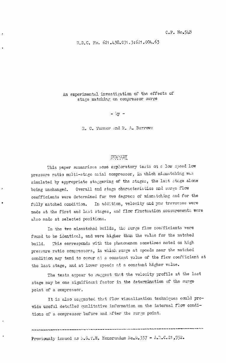
An experimental investigation of the effects of stage matching on compressor surge
- by -
This paper summarises some exploratory tests on o low speed low
pressure ratio multi-stage a;:ial compressor, in rJhich mism2Ltchi.q w&s simulated by appropriate staggering of the stages, the last ztrgo alone
being unchanged. Overall and stage characteristics anil surge flow
coefficients were determined for two degrees of mismatching and for the
fully matched condition. In addition, velocity and yaw traverses were
made at the first and kst stages, and flow fluctuation measurements were
also made at selected positions.
In the two mismatched builds, the surge flow coei"ficients were
found to be identical, and were higher than the value for the matched
build. This corresponds with the phenomenon some-times noted on high
pressure ratio compressors, in which surge at speeds near the matched
condition may tend to occur at a constant value of the flow coefficient at
the last stage, and at lower speeds at a constant higher value,
The tests appear to suggest thr,t the velocity profile at the last
stage may be one sigtxificant 1: "ector in the determination of the surge
point of a compressor.
It is also suggested that flow visualisation technic~ues could pro-
vide useful detailed cLualitative information on the internal flow condi-
tions of a compressor before and after the surge point,
Previously issued as N.G.T.E. Xemorandum NoJi.337 - AAC. 21 ,352.
-2-
COWI%VTS ---*li--
1.0
2.0
3.0
4.0
5.0
Introduction
Pa@ -.
4
Apparatus and measurements 4
2.1 The compressor 2.2 Neasurements
Tect technique and presentation of results
4 5
6
Discussion 6
4.1 Significance of tests 4.2 General 4.3 Some related work on surge
Conclusions
6 7 8
9
Notation
References
Detachable Abstract Cards
No&
I
II
Blade design details
hote on the wlculetion of the parameters
II
12
13
14

-3-
Fig. No.
1
2
3
4
5
6
7
8
9
IO
II
12
13
24
15
16
Title .
Assembly of compressor
Build 1. Overall characteristics
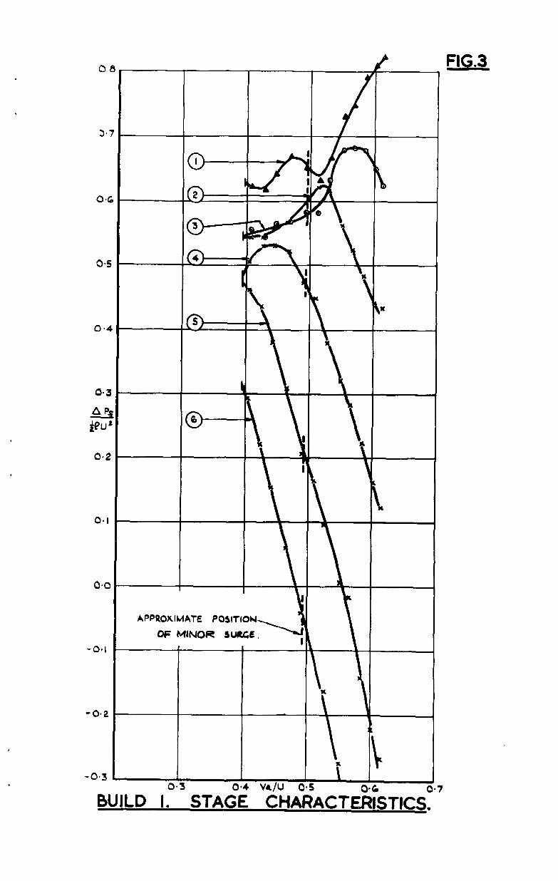
BuXLd 1. Stage characteristics
Build 1. Axial veloci.ty and yaw traverses after Stages 1 and 6 prior to minor surge
Build f. Axial velocity and yaw traverses after Stages 1 and 6 prior to surge
Build I. Amplitudes of pressure fluctuations through stages prior to surge
Z3uild 1. Amplitudes of pressure fluctuations through stages during surge
Build 2. Overall characteristics
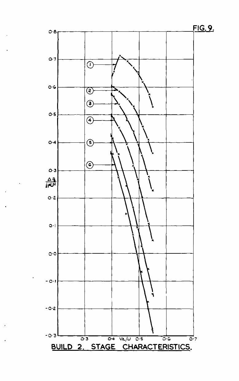
Build 2. Stage characteristics
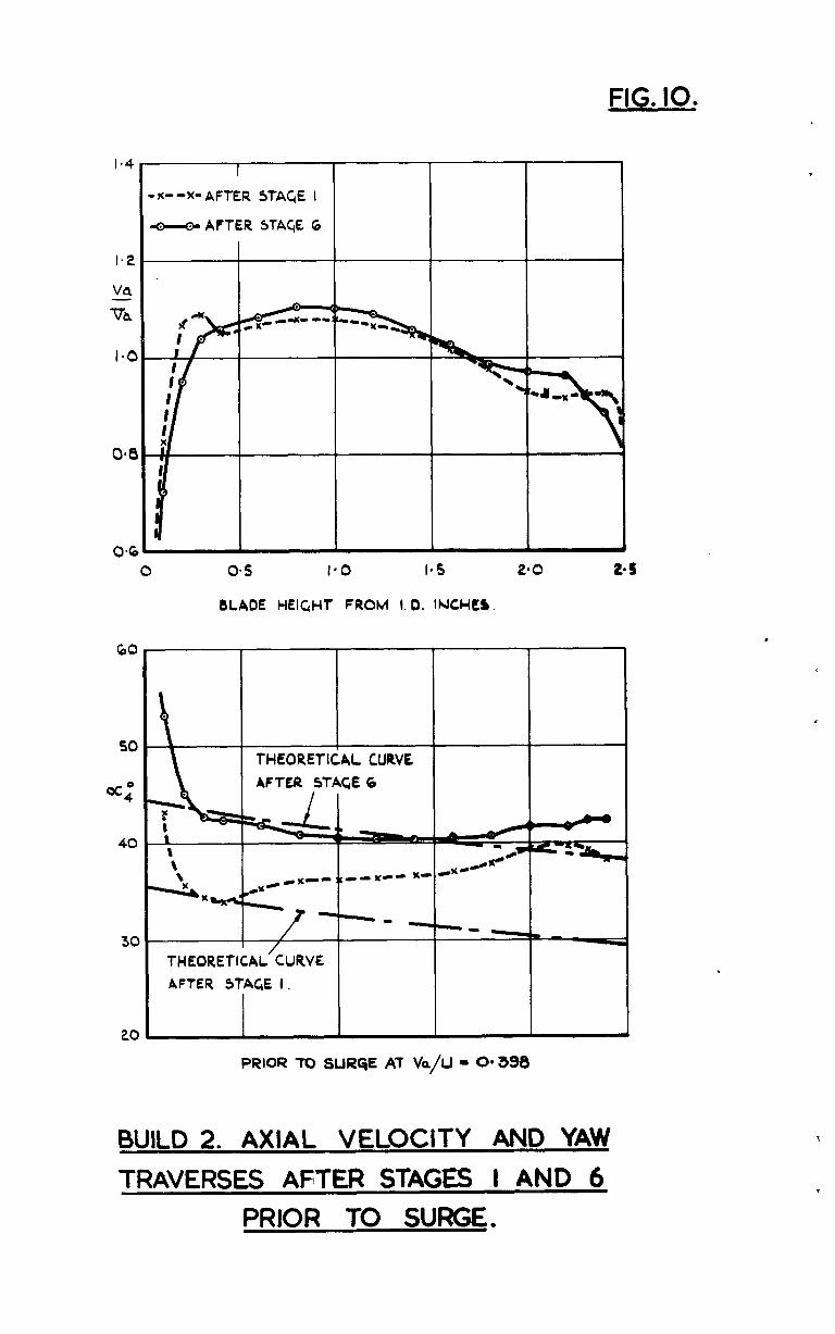
Build 2. Axial velocity and yaw traverses after Stages I and 6 prior to surge
i3ulLd 2. Amplitudes of pressure fluctuations through stages before and after surge point
Build 3. Overall characteristics
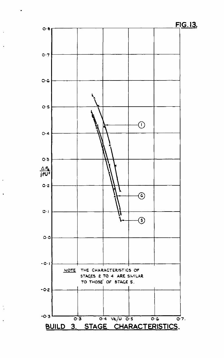
Build 3. Stage characteristics
All builds. Characteristics of Stage 6
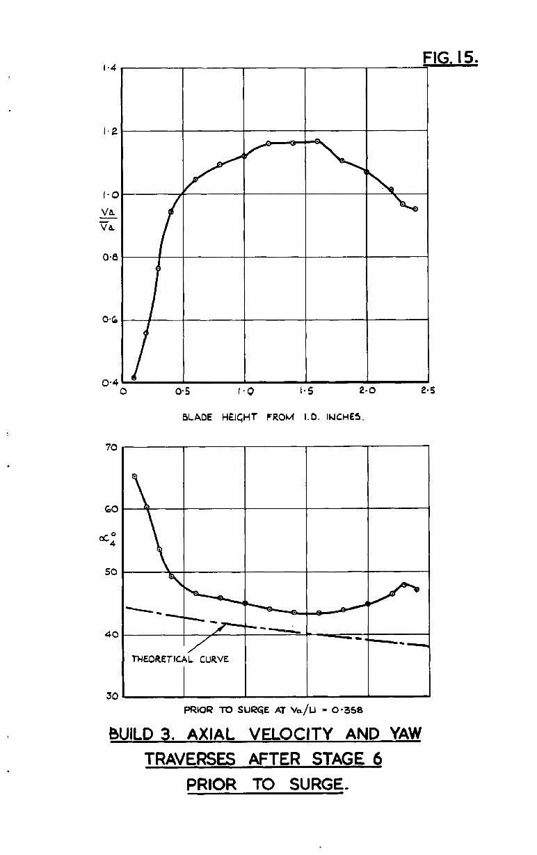
3uild 3. Axial velocity and yaw traverses after Stage 6 prior to surge
Build 3. Amplitudes of pressure fluctuations through stages before and after surge point
All builds, Mean diameter rotor incidences at surge relative to theoretical stalling incidences
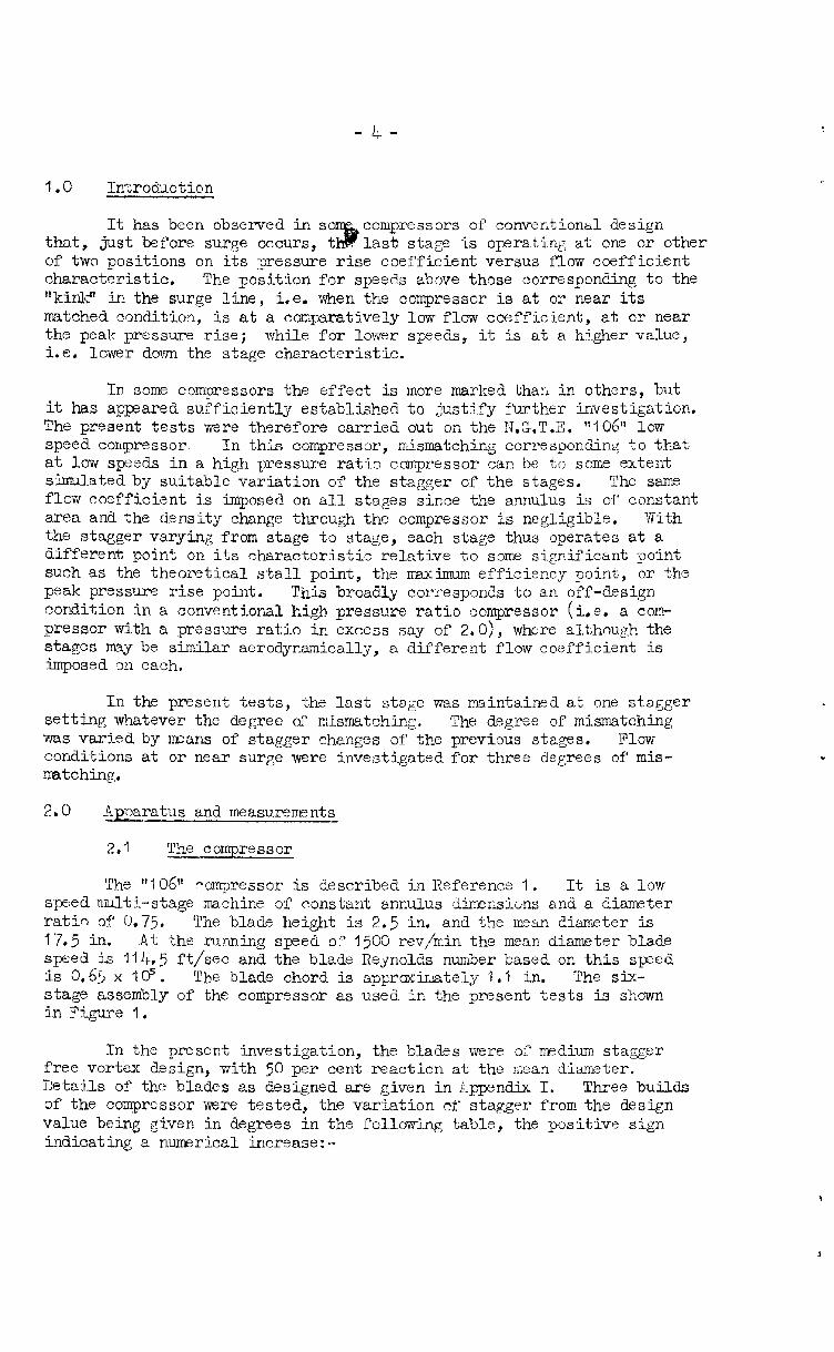
1.0 Introduction
It has been observed in s corn-press 0x-s of conventional design that, just before surge occurs, last stage is operating at one or other of two positions on its pressure rise coefficient versus flow coefficient characteristic. The position for speeds above those corresponding to the lfkinklr in the surge line, i.e. when the compressor is at or near its matched condition, is at a comparatively low flow coefficient, at or near the peak pressure rise; while for lower speeds, it is at a h?gher value, i.e. lower down the stage characteristic.
In some compressors the effect is more marked than in others, but it has appared sufficiently established to justify further investigation. The present tests were therefore carried out on the N.G.T.B. "106" low speed compressor, In th<.s compressor, mismatching corresponding to that at low speeds in a high pressure ratio compressor can be to some extent simulated by suitable variation of the stagger of the stages. The same flow coefficient is imposed on all stages since the annulus is of constant area and the density change through the compressor is negligible, Vith the stagger varying from stage to stage, each stage thus operates at a different point on its characteristic relative to some significsnt point such as the theoretical stall point, the maximum efficiency point, or the peak pressure rise point. This broadly corresponds to an off-design condition in a conventional hi@ pressure ratio compressor (i.e. a com- pressor with a pressure ratio in excess say of LO), where although the stages may be similar aerodynamically, a different flow coefficient is imposed ,on each.
In the present tests, the last stage was maintained at one stagger setting whatever the degree of mismatching. The degree of mismatching was varied by means of stagger changes of the previous stages. Flow conditions at or near surge were investigated for three degrees of mis- Illatching,
2,O $Eratus and measurements
2.1 The compressor
The "106" compressor is described in Reference 1. It is a low sped niulti-stage rrachine of constant annulus dimnsims and a diameter ratio, of 0,75* The blade height is 2.5 in. and the mean diameter is 17.5 in. At the running speed of 1500 rev,/min the mean diameter blade
ft/ see and the blade Reynolds number based on this speed The blade chord is approx-irately I.1 in. The six-
stage assembli of the compressor as used in the present tests is shown in Figure 1.
.
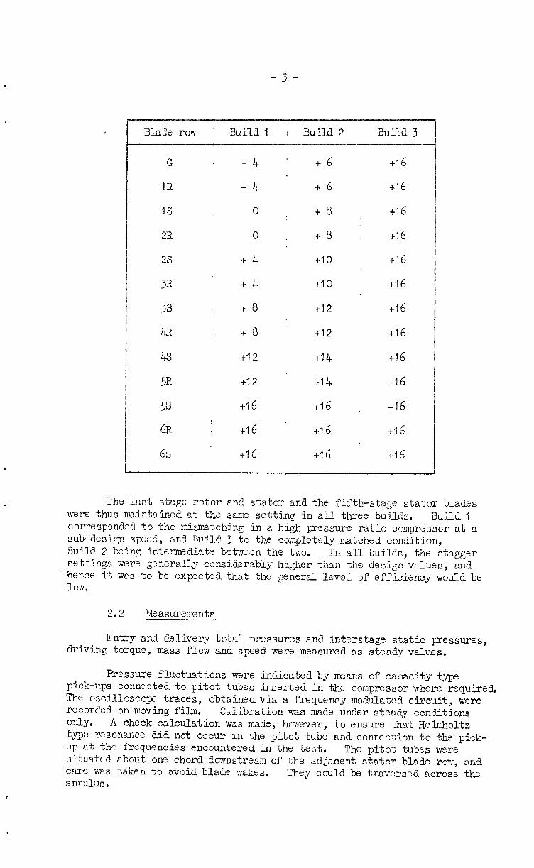
In the present investigation, the blades were of odium stagger free vortex design, with 50 per cent reaction at the mean diameter. Details of the blades as designed are given in kppendix 1. Three builds of the compressor were tested, the variation of stagger from tine design value being given in degrees in the following table, the positive sign indicating a numerical increase:-
i
J
-tj-
I Blade row ' Build.1 : Build2 Build3
--
G -4
IR - 4-
IS 0
2R 0
2s +4
31’ +4
3s +8
4R t8
r& i.12
5R +I2
5s i-16
6x1 +16
6s l-l 6
+6
+6
+8
+8
+I0
+I0
+I2
+I2
+I4
+I 4
-t-16
+I 6
+16
+I6
+16
+I 6
+16
r-16
+I 6
+I 6
+-I 6
+16
-1-16
+16
+I 6
f-16
The last stage rotor and stator and the fifth-stage stator blades were thus maintained at the same setting in all three builds. Build 1 corresponded to the misrratching in EI high pressure ratio compresscr at a sub-design speed, snd 13u41d 3 to the completely matched condition, Build 2 being intermediate bet-men the two. In all builds, the stagger settings were genera.lly considerably higher than the design values, and
' hence it was to be expected that + ,he generzl level of efficiency would be low.
2.2 geasurements
Entry and delivery total pressures and interstage static pressures, driving torque, mass flow and speed were measured as steady values.
Pressure fluctuations were indicated 3y Means of capacity type pick-ups connected to pitot tubes inserted in the cor~pressor where required, The oscilloscolx: traces, recorded on moving film.
obtained via a frequency modulated circuit, were
Only. Calibration was made under steady conditions
A check calculation was made, however, to ensure that Helmholtz type resonance did not occur in the pitot tu3e and connection to the pick- up at the frequencies encountered in the test, The pitot tubes were situated about one chord dofJnst,ream of the adjacent stator blade row, and care was taken to avoid blade wa7kes. They could be traversed across the annulus.
-6- ,
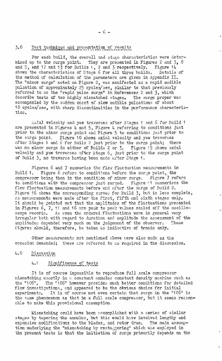
390 Em- ‘ Test technique andLresentatlon of re.ults --- -.s>a *-*- :._-~..*z-..,
For each build, the overall and stage characteristics were deter- mined up to the surge point, They are presented in Figures 2 and 3, 8 ma 5, and 12 and 13 for Builds /i, 2 and 3 respectively. Figure 14 shows the characteristics of Stage 6 for all three builds. Details of the method of calculation of the parameters are given in Appendix II. The "minor surge" noted on Figure 2, was manifested as a rapid audible pulsation of approximately 25 cycles/set, similar to that previously referred to as the "rapid pulse surge" in References 2 and 3, which describe tests of two highly mismatched stages. The surge proper was accompanied by the sudden onset of slow audible pulsations of about IO cycles/set, with sharp discontinuities in the performCance characteris- tics.
Axial velocity and yaw traverses after Stages 1 and 6 for Build 1 are presented in Figures l+ and 5, Figure 4 referring to conditions just prior to the minor surge point and Fimre 5 to conditions just prior to the surge point. Fi,qre IO shows axial velocity and yaw traverses after Stages I and 6 for Build 2 just prior to the surge point; there was no minor surge in either of Builds 2 or 3. Figure 15 shows axial velocity and yaw traverses after Stage 6, just prior to the surge point of Build 3, no traverse having been mnde after Stage I.
Figures 6 and 7 summarise the flor;J fluctuation measurements in Build 1. Figure 6 refers to conditions before the surse point, the compressor being then in the condition of minor surge. Eigure 7 refers to conditions vsith the compressor just surged. Figure 11 summarises the flovr fluctuation measurements before and of'ter the surge of Build 2. Figure 16 shows the corresponding curves for Build 3, but is less complete, as measurements were made after the first, fifth and sixth stages only. It should be ;?ointed out that the m$litudes of the fluctuations presented in Figures 6, 7, II and 16 are peak to pe a!; v&lues scaled off the oscillo- scope records. As even the ordered fluctuations were in general very irregular both with regard to aura tion and amplitude the assessment of the amplitudes depended very much on the judgement of the observer. These figures should, therefore, be taken as indicative of trends only,
Other measurements not mentioned above \:ere also made as the occasion demanded; these z,re referred to as required in the discussion,
4.0 Discussion -aran .a a.- -
4.1 Si.ificance of tests "Z -~.~%-s~*-y__ fza *. wit-
It is of course impossible to reproduce full scale compressor mismatching exactly in a constant annulus constant density machine such as the "106". The ",06" however provides much better conditions for detailed flow investigations, and appeared to be the obvious choice for initial experiments, It is of course not even certain that surge in the "106" is the same phenomenon as that in a full scale compressor, but it seems reason- able to make this provisional assumption.
Mismatching could have been accomplished with a series of similar stages by tapering the annulus, but this would hr,ve involved lengthy and ex$en;ive modifications to the blades, and rotor drum. The main assump- tion underlying the "mismatching by restaggering" which was employed in the present tests is that the initiation of surge primarily depends on the
-7-
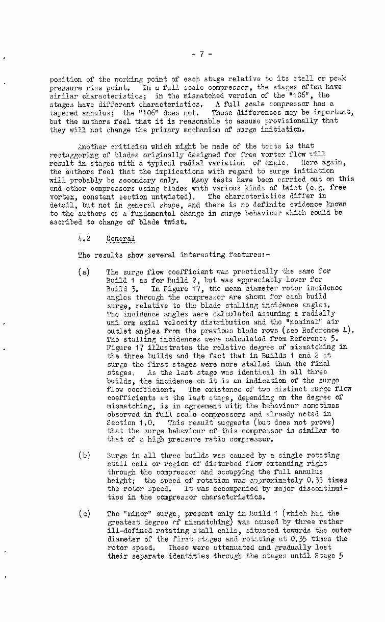
position of the working point of each stage relative to its stall or peak pressure rise point. In a full scale compressor, the stages often have similar characteristics; in the mismatched version of the "lQ6", the stages have diff'erent characteristics. A full scale compressor has a tapered .~~IUIU~US; the "106" does not. These differences may be importnnt, but the authors feel that it is reasonable to assume provisionally that they will not change the primary mechanism of surge initiation.
Another criticism which might be made of the tests is that restaggering of blades originally designed for free vortex flow vi11 result in stages with a typical radial variation of angle. Xere again, the authors feel. that the implications with regard to surge initiation will probably be secondary only. Many tests have been carried out on this and other compressors using blades with various kinds of twist (e.g. free vortex, constant section unM.sted), The characteristics differ in detail, but not in general shape, and there is no def~inite evidence known to the authors of a fundmontal change in surge behaviour which could be ascribed to chaylge of blade twist.
The results show several interesting features:-
(4 The surge flow coefficient was practically the same for Build 1 as for ?ki.ld 2, but was appreciably l&-er for Build 3. In Figure 47, the mean diameter rotor incidence angles through the comprcszor are shown for each build surge, relative to the blade st,LLling incidence angles, The incidence angles were calculated assuming a radially uni.'orm axial velocity distribution and the "nominal" air outlet angles from the previous blade rows (see Reference 4). The stalling incidences were calculated from Reference 5. Figure 17 illustrates the relative degree of mismatching in the three builds and the fact that in Builds I and 2 3-L surge the first stage s were more stalled than the final stages o As the last stage was identical in all three builds, the incidence on it is an indication of the surge flow coefficient. The existence of two distinct surge flow coefficients at the last stage, depending on the degree of mismatching, is in agreement with the behaviour sometimes observed in full scale compressors and already noted in Section 1.0. This result suggests (but does not prove) that the surge behaviour of this compressor is similar to that of E high pressure ratio compressor.
b) Surge in all three builds was caused by a single rotating stall cell or region of disturbed flow extending right through the compressor cand occupying the full annulus height; the speed of rotation was ~~~;x*oximetel.y 0.35 times the rotor speed. It was accompanied by major discontinui- ties in the compressor characteristics.
(4 The ttminor" surge, present onl-7 in Huild 1 (ahich had the greatest degree ~3' mismatching I was caused by three rather ill-defined rotating stall celL3, d.tw~a towards the outer diameter of the first stsges and rotcting at 0.35 times the rotor speed, These were attenuated and gradually lost their separate identities through the stages until Stage 5
- co, -
was reached, after which the floe vas steXly; irregular fluctuations mere epL)arent pfter 3tage 6, holrever (Figure 6). Li"'-te1* the first stage, the a:&1 velocity as indicated by conventional pitot and static -i;ubes was reversed towards the outer diameter (Pigure 5); the presence of the stall cells may have affected the measurer ments to some extent. There IYFLS no discontinuity in the overall characteristics, but the efficiency reached its peak value when the minor surge commenced, :;ith a slight change of curvature in the temperature rise coefficient curve, The stage characteristics (Figure 3) show that the first three stages were operating on the low flow side of their peak pressure rises. Stall cells are of course com- monly found in the first stages of high pressure ratio com- pressors opereting at sub-design speeds near the surge line. ;:hen they do not give rise to discontinuities in the stage characteristics they are usually described as 8'progessivet', as distinct from frabrupt" and generally extend across part of the annulus only, as in trie present case - see Reference 6.
In I!uild 2 (which had a lesser degree of mismatching), just before surge, no stall cells were epparent, but there were appreciable flow fluctuations, the largest being at the outer diameter ef'ter the first stages. They were attenu- ated through the later stages. Inspection of the yaw tra- verses after the first stage (Figure 10) surgested moderate stalling towards the outer diemeter. The first stage alone passed its peak pressure rise before surge.
In Euild 3 (in which the stages were fully matched), just before surge, no stall cells were a:l$arent, but there were large random pressure Julses towards tie inner diameter after the last stage stator blades.
Change of stagger of the last stator blade row by *IO0 in any of the three builds did not affect the surge flow coefficient.
In Builds 1 and 2, the axial velocity and yaw -traverses after the last stage were similar in general shape just prior to surge, the peak velocity being towards the inner diameter; the profiles after the first stage were, however, considerably different, nith reversed mean flow in Build 1 at the outer diameter. In Build 3, the velocity profile after the last stage at surge was peaked towards the outer diameter, with a v:ell marked region of low flow at the inner diameter,
@me related ?,iork on sur& --a I-s.., - 2M _y_z-
Reference 7 gives a useful eccount of surging in high pressure ratio multi-stage compressors The type of surge usually met with is described as surge due to "<:-bru-ot stall",
stall followed b$ recovery, consisting of a cyclical entry
into an abrupt v;ith corresponding changes ir tile net flow, By "abrupt stall" is meant a major discontinuous change in the compressor characteristics, accompanied by a rotating stall cell extending right through the compressor. This obviously corresponds to
-9 -
the "surgel! of the present tests, in which no cyclic variation in the net flow was however noted, The existence and characteristic; of the cyclic variation would be expected to depend largely on the aasocietcd ducting.
The factor which appears colnmon to the sfsurge" of the full scale compressor connected to ducting and to the "surge" of the present tests, however defined, is the sudden change of the flow Tattern, 15th the inception of the rotating cell extending through the comi,7ressor. The instrumentaticn in the .y>resent tests wa3 not adaptable to detailed investigations of the flot7 patterns during surge, snd so it is not possible to say definitely how the cell differed if at all from the kind :7hich is usuelly localised in the first stages of a mismatched compressor - as in the "minor surge" of Build I - and which has been given extensive theoretical treatment on a ti;o-dimensional basis, as for instance summarised in Reference 6.
There is, however, evidence that the fiow during surge of a full scale multi-stage compressor embodies a si.gni.f'icant degree of recircula- tion or reverse flow. Unpublished test results at N.C.T.E. have SAOWD that the temperature of the middle stages of a compressor during surge may rise to a value which is explicable only on the assumption of recirculation, and which may result in destruction of the blades.
It is therefore possible that surge as normally understood is caused by the inception of a rotating regime of reverse or recirculating flOV?, The instrumentation of the Tresent tests was not suitable for distinguishing reverse flow, and this may well have applied to the tests described in Iicference 6. That there was flow reversa!. at surge was su,:gested by the behaviour of wool tufts held in front of the inlet. Reference 8 does in fact state th2t reverse flows are often detectable in low speed fans when surged, and possibly also in high pressure ratio com- pressors. Reference & 31~0 gives a qualitative treatment of surge on the basis of one half of the compressor blowing back through the other half.
Reference 9 suggests that instability mz:7 be initiated in c", stage by reverse flow occurring at the inner diameter, conserlent upon deteriora- tiqn of the velocity ,:rofile, the deterioration occurring independently of blade stslling, which,hol-ever, in a practical case would c,cconA)any it. In the present tests, the velocity profile at ';he outlet of Build 3 was very 107~ towards the inner diameter just prior to surge, and some such criterion might therefore apply 75th this build, An examination of the outlet velocity profiles at surge of a number of full scale compressors might be rewsrding in this respect,
In Builds 1 and 2 hovever, the outlet profiles showed no evidence of deterioration, although there was a average reverse f'lol;,r it the outer diameter of the first stage during the minor surge. Further theoretical treatment would obviously be facilitated by a more detailed quslitative knoTTledge of the flow just before 2nd just after surge; this might well be obtained by some form of flow visualisation technique used for instrvlce 0% a 10~ s;>eed 10~; pressure ratio compressor assembled as in the present tests to simulate the various degrees of mismatching encountered in a full scale compressor.
5.0 Conclusions -ez_L --
Six stages of bleding have been tested in a la-1 speed low pressure ratio com-oressor in the matched condition =and with two degrees of mis- 2. matching. The mismetchtig :;as obtained by the progressive re-staggering
- :o -
of the stages through the compressor, -the lest stqe beiq at 'ihe scme stagger setting in all three builds. The flow conditions h;tve been examined in detail at flows near surge, both velocity distributions and $ressure fluctuations being investigated.
The surge flow was found to be identical for the two mismatched conditions and wes higher than that for the matched condition. This result agrees with experience on some full scale com;zessors where the surge at qeeds in the mismatched condition below the surge line kink tends to occur at one flow coefficient at the last stage, while that at higher speeds (i.e. nearer the matched condition) occurs at a lower value. It also suggests that the surge behaviour of the present tests setisfac- torily simulates that to be found in some high pressure ratio compressors.
Before the surge in the two mismatched builds, tire initial stages showed evidence of stalling a-t the outer diameter, in one case with definite rotating cells and reverse mean flow, the f1o-z improving pro- gressively throqh the compressor, Just prior to surge, the velocity profile after the lest stage WCS very similar in the Tao builds, the flow being peaked toaards the inner diameter.
In the matched build, there eras no evidence of stalling the first stage prior to surge. The outlet a;&1 velocity was peaked tor.rards the outer diameter, ilith a region of very 10~ velocity to:-:ards the inner diameter, where large random pressure fluctuations were observed.
It is suggested that norme. compressor surge could be associated with rotating regions of reverse or recirculeting flow, :_:.nd that one of the conditions determining its inception rnq be the vsloc'.ty profile at the last stcge. The visuali*;ation or" the flow just before 2nd just after surge in a multi-stage compressor to:*ether with an examinetion of" the outlet velocity profiles at surge of typical high pressure ratio compre:;- sors might therefore prove to bc usef'ui eqerimentsl techniques.
-11 -
U
va
nr
AT
C
i
I:
9
t
a
P
0
P
r
z
=
z
=
=
=
=
=:
=
C
ZZ
=
=
=
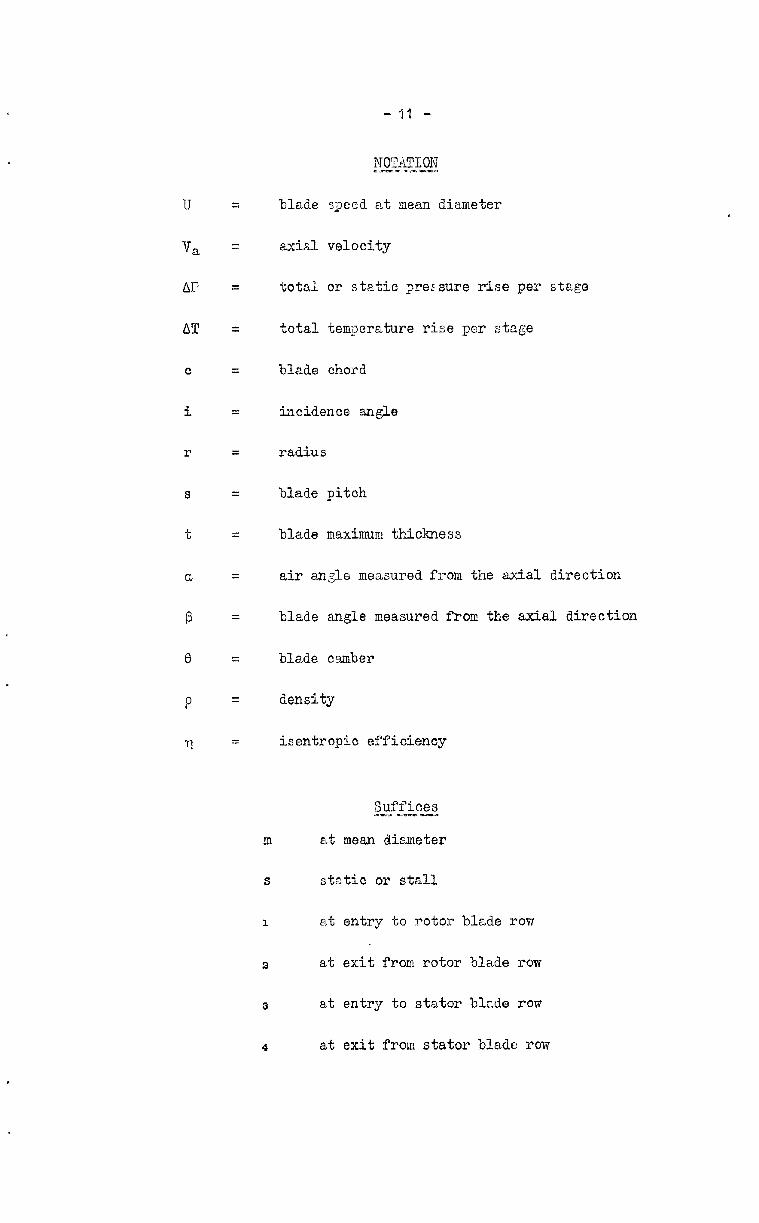
axial velocity
total or static gre5sure rise per stage
total temperature rise per stage
blade chord
incidence angle
radius
blade pitch
blade maximum thickness
air angle measured from the axial direction
blade <angle measured from the axial direction
blade camber
density
isentropic efficiency
Suffices es- s---m
m at mean diameter
S static or stall
1 at entry to rotor blade row
2 at exit from rotor blade row
3 at entry to stator bkde row
4 at exit from stator blade row
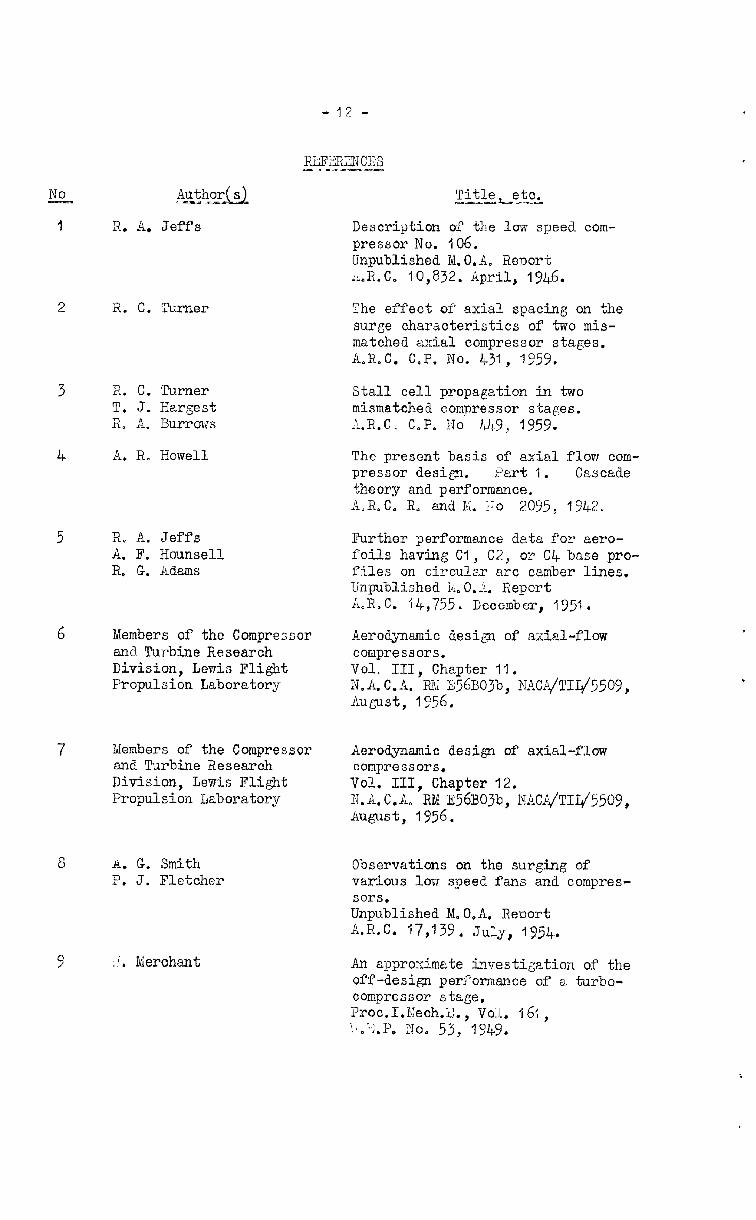
Authoru c-r-*
R. A. Jeffs
R. C. Turner
X. C. Turner T. J. Hargest R, A, Burrows
A. R, Howell
R. A. Jeffs A, F. Hounsell R. G. Adams
Members of the Compressor and Turbine Research Division, Lewis Flight Propulsion Laboratory
Members of the Compressor and Turbine Research Division, Lewis Flight Propulsion Laboratory
u. G. Smith P. J. Fletcher
i!'. Merchant
Description of the low speed com- pressor No. 106. Unpublished M.O.A. Report AR.C~ 10,832. April, 1946.
The effect of axial spacing on the surge characteristics of two mis- matched axial compressor stages. A.R,C. C.P. No. 431, q959.
Stall cell propagation in two mismatched compressor stages. &R.C, C,P. No &9, 1959.
The present basis of axial flow com- pressor design. Part d. Gas cade theory and performance. A,R.C. R, and K. Iio 2095, A942.
Further performance data for aero- foils having Cl, C2, or C4 base pro- files on circular arc camber lines. Unpublished W,O,I. Report k,R. c. f&,755. December, 1951.
Aer0d;ynami.c design of axial-flow compressors. Vol, III, Chapter 14. N.A.Cc,A. RX 256B03b, NAC1;/TIL/55,09, August, I 956.
Aerodynamic design of axial-flow compressors. Vol. III, Chapter 12. M.B.C.A. RM E56B03b, I'TAC&/TIL&j509, August, 1956.
Observations on the surging of various losr speed fans and compres- sors. Unpublished M,O,A. Res?ort &KC. 17,139. July, 1954.
An approximate investigation of the off-design performance of a turbo- compressor stage, Proc I.Mech 2 i 1’ 0 %i. Yo.
vol. 16,;, k,;'lY,Y*
- “I3 -
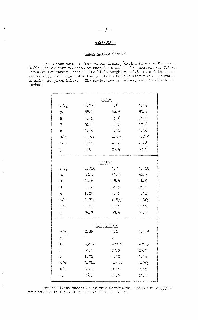
Elade design details
The blades mre of free vortex Sesign (design flow coefficient = Q.667, 50 per cent rezztion at mean diCmeter). The sectkm was C,4 on circular arc camber lines. The blade height was 2.5 in. and the mean radius 8,75 in. The rotor has 58 blades and the stator 60. Further details are given below, The nn,Qes are in degrees and the chords in inches.
I f Rotor I r/r, 0,874 1.0 1 ,I.!+
1 131 39.2 46.5 50.6
i P2 -3*5 15.4 32.0
1 0 42.7 30.9 18.6 ! i
j c ;,I& 1.10 7.06 I
i s/c 0.726 I x/c 0.12 0.862 I .020 I 0.10 G.08 I
j5 23.4 37.8 /
i stator ----i I I^---
0.860 l.G 1.125
53.0 L6.1 42.2
13.6 15.9 14.0 I
jj.4. jo,2 2ti.2 i i
I 0 I .06 1 .;o 1 .lL I i S/C 0*7&J+. 0,833 0.905 i $2 0. IO 0.91 0.12 1
t
Rx- the tests described in this Memrandm, the blade stagger-s were varied in the mnnes Iindicated in the test,
-IL,-
AIJImDlx II
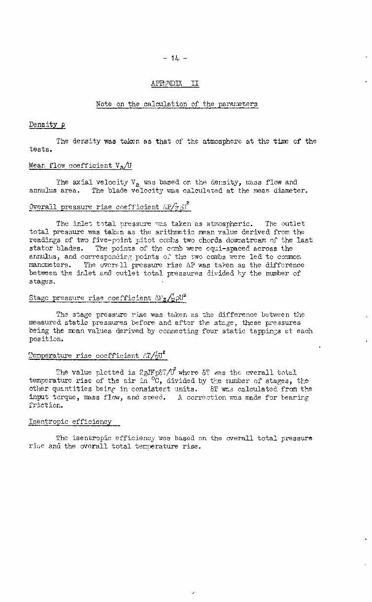
Note on the calculation of the parameters
Density p
The density was taken as that of t'he atmosphere at the tisile of the tests.
Mean flow coefficient V&J
The axial velocity V, was based on the density, mass flow and annulus area. The blade velocity was calculated at the mean diameter.
Overall pressure rise coefficient Al?/-$$J*
The inlet total pressure WLS taken as atmospheric. The outlet total pressure was taken as the arithmetic mean value derived from the readings of two five-point pitot combs two chords downstream of the last stator blades. The points of the comb ;yere equi-spaced across the annulus, and corresponding points oi' the two combs were led to common manometers. The overall pressure rise AP was taken as the difference between the inlet and outlet total pressures divided by the number of stages.
Stage pressure rise coefficient L$s/$pUa
The stage pressure rise was taken as the difference between the measured static pressures before and after the stage, these pressures being the mean values derived by connecting four static tappings i2t each position.
Temperature rise coefficient AT&J*
The value plotted is 2gXp6T/l?where 6T was the overall tote1 temperature rise of the air -in 'C, divided by the number of stages, the other quantities being in consistent units. ST W&S calculated frczn the input torque, mass flow, and sr=ed. A correction was made for bearina c ) friction.
Isentropic efficiency
The isentropic efficiency was based on the overall total pressure rix and the overall total temperature rise.
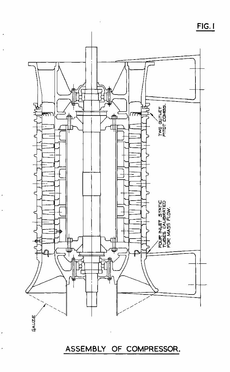
FIG. I
/- / I
ASSEMBLY OF COMPRESSOR.
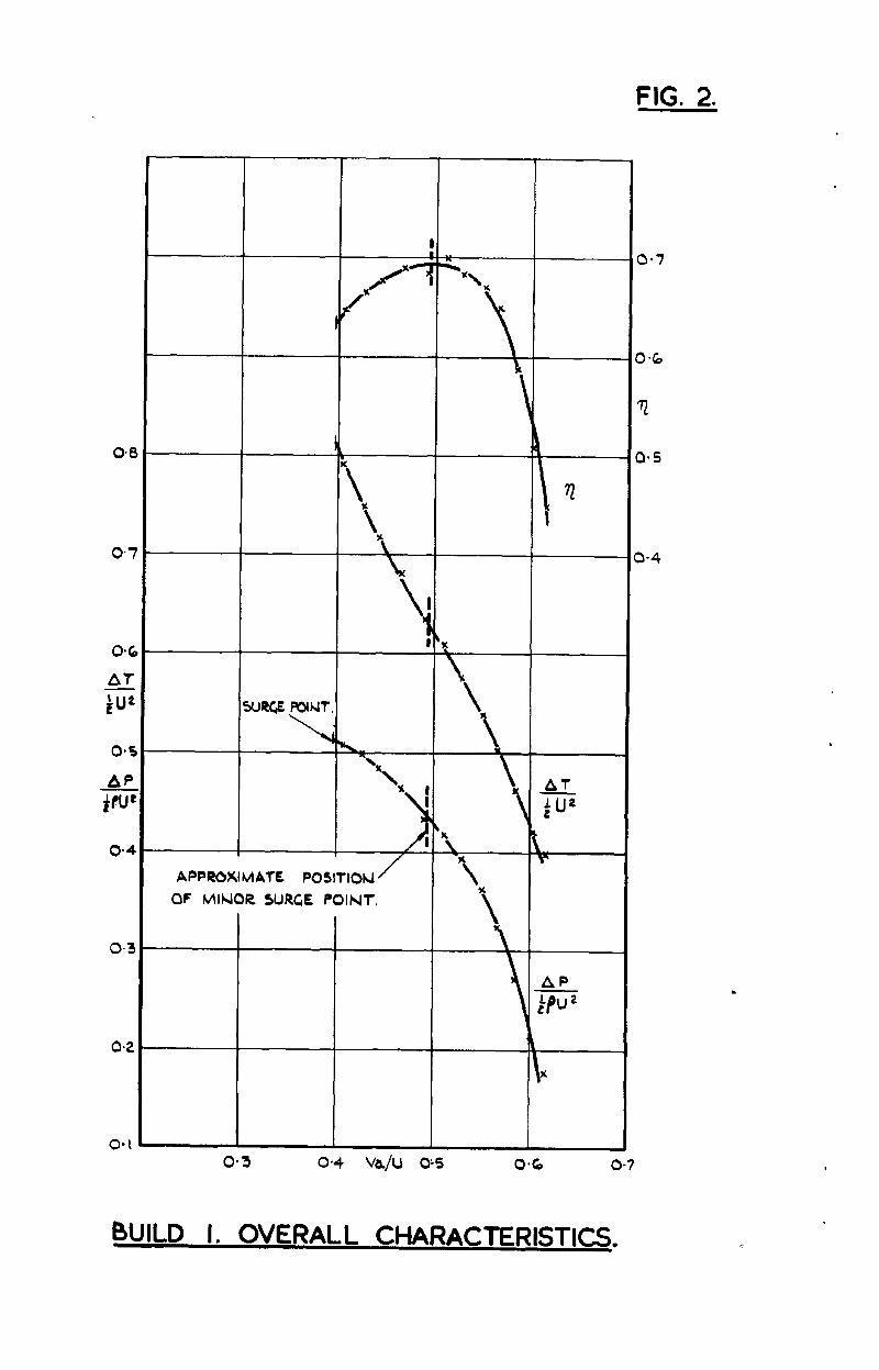
FIG. 2.
APPROXIMATE P03lTION APPROXIMATE P03lTION
OF MINOR SURGE OF MINOR SURGE POINT. POINT.
AT AT TJji TJji
, ,
\. \.
Y Y
\
AP
rLPu *
O-6 o-7
APPROKIMATE PQSiflON
OF MhNwz SuGf .
BUILD 1. STAGE CHARACTERISTICS.
FIG.3
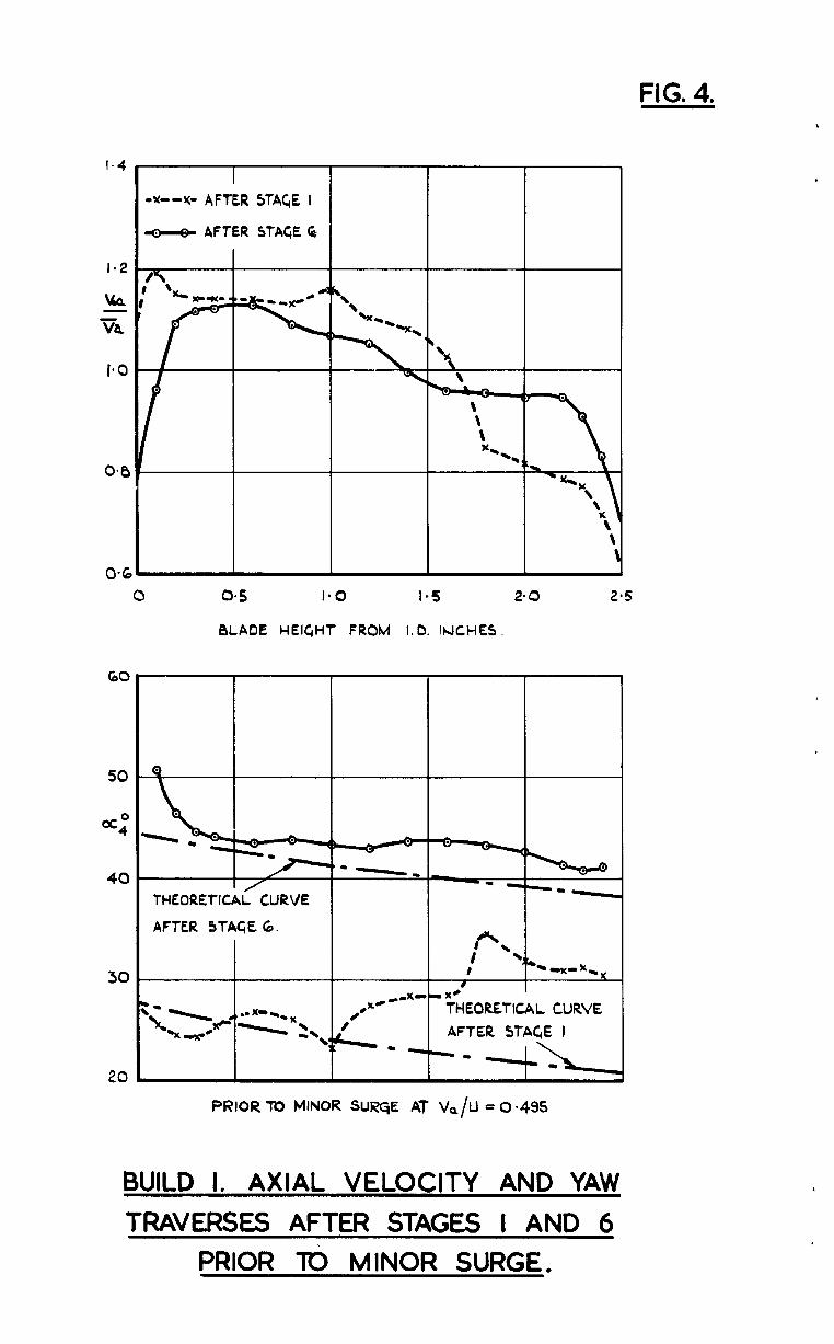
FIG. 4.
I.4
l-2
k
BLADE HEIGHT FROM 1.0. INCHES,
60
50
=:
40
30
20
I ,x--Y- AFTER STAC,E I
u AFTER STAGE Gi
AFTER STAGE 6.
THEORETICAL CURVE AFTER 5TAC& 1
PRIOR TO MINOR SUQE AT i/&l = 0.495
BUILD 1. AXIAL VELOCITY AND YAW TRAVERSES AFTER STAGES I AND 6
PRIOR To MINOR SURGE.
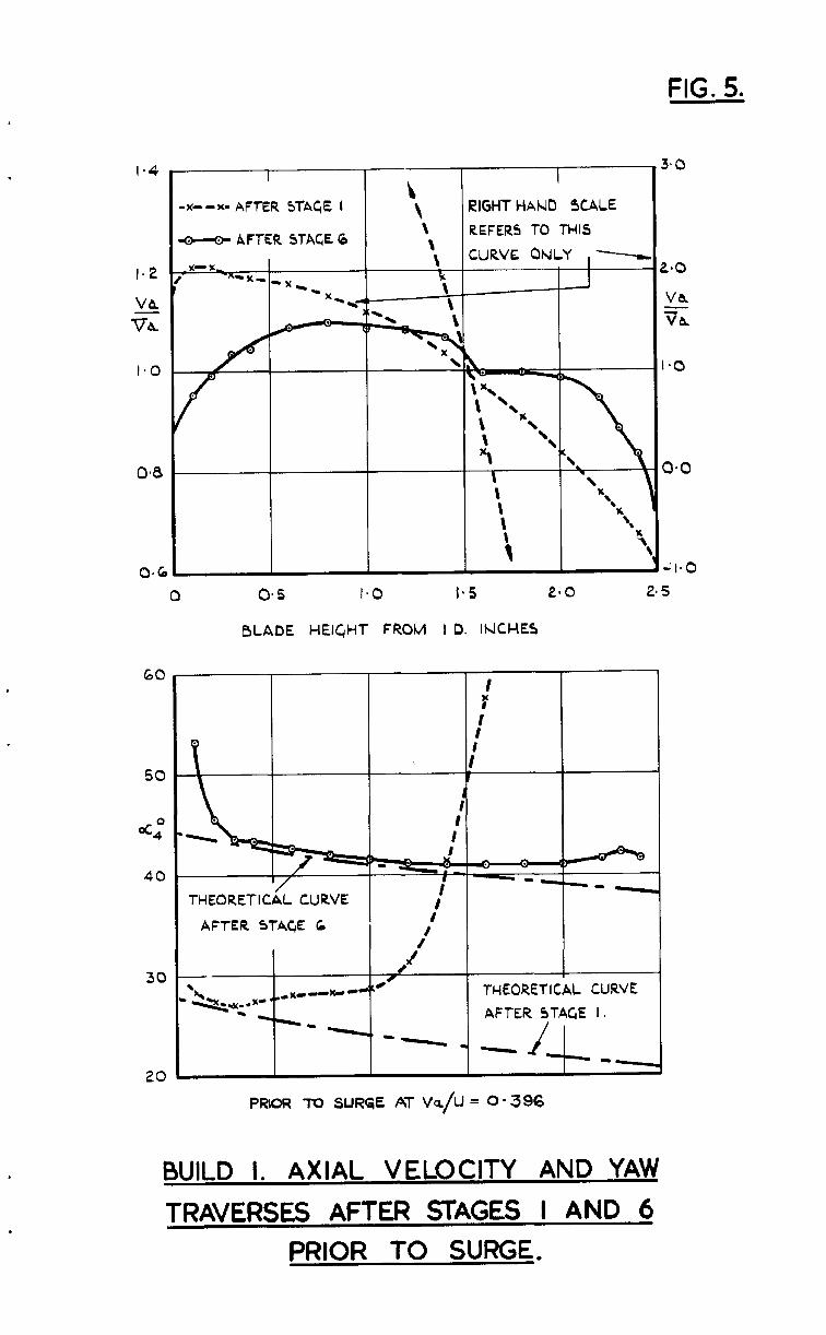
FIG. 5.
60
50
4
40
30
20
\ x--x- AFTER STAGE I \ RIGHT HAND SCALE
\ REFERS TO THIS \ \ CURVE ONLY
\ -x \ ‘I& \ ‘.
i
x -3
BLADE HEIGHT FROM I D. IhlCHES
THEORETlCiL CURVE
AFTER STAGE 6
I r’ 1
/ I J 0-
1 TWEORETICAL CURVE
AFTER STAGE I.
PRIOR TO SURGE AT k/u = o- 396
BUlLD I. AXIAL VELOCITY AND YAW
TRAVERSES AFTER STAGES I AND 6 PRIOR TO SURGE.
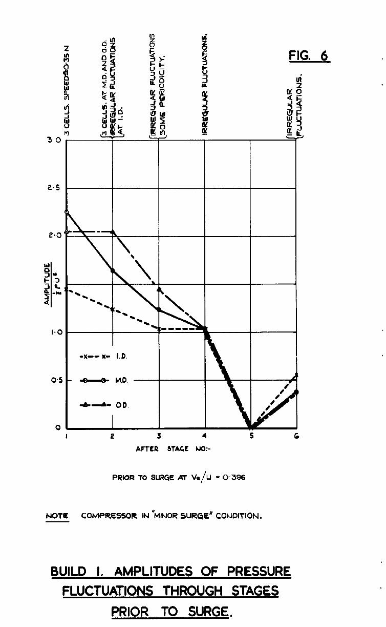
FIG. 6
0x-m K- I.D.
- - M.D.
-b-- 00.
I 2 J 4 5 c
AFTER WAGE NO:-
PRIOR TO SURGE #r V,/U = 0.396
NOT% COMPIPESSOR IN ‘MINOR SUR& CONDITION.
BUILD 1. AMPLITUDES OF PRESSURE FLUCTUATIONS THROUGH STAGES
PRIOR TO SURGE,
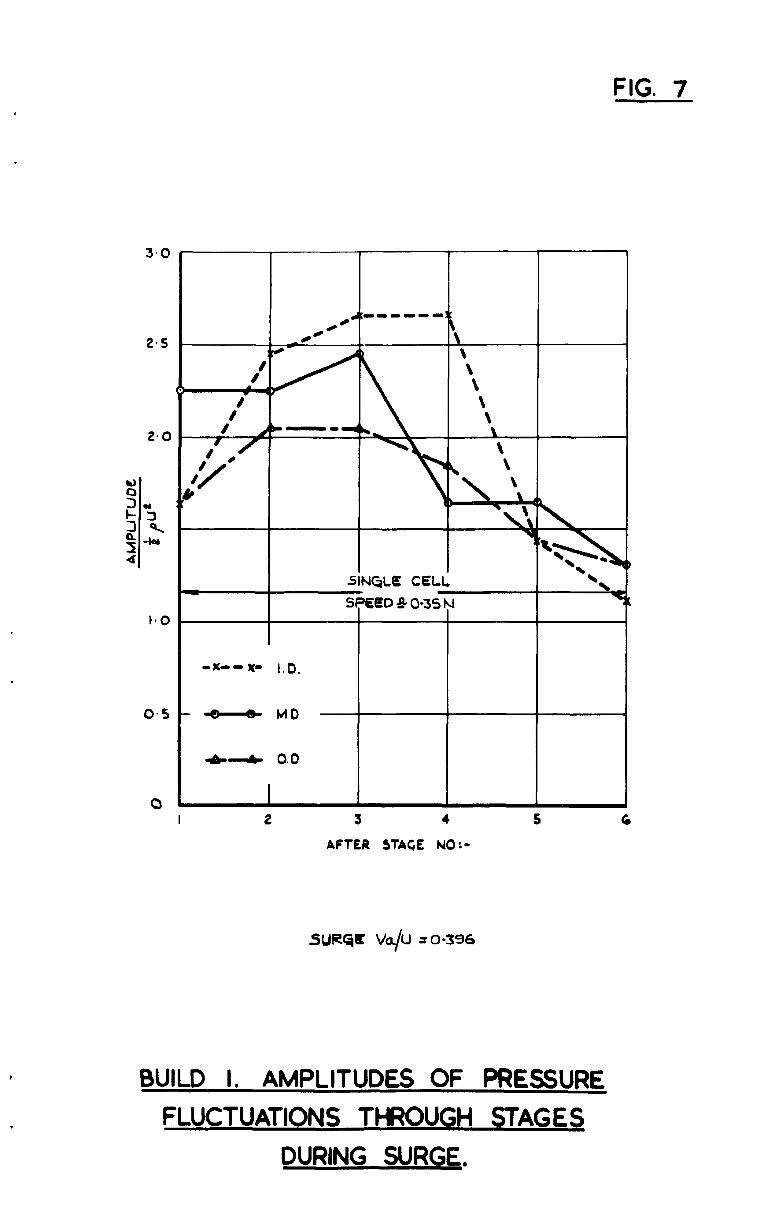
FIG. 7
0 I 2 3 4 5 c
AFTER STAGE NO:-
SURQC k/U ~0-356
BUILD I. AMPLITUDES OF PRESSURE FLUCTUATIONS THROUGH STAGES
DURING SURGE.
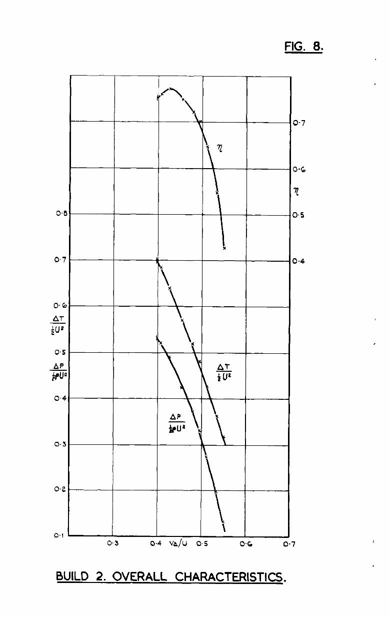
FIG. 8.
BUILD 2. OVERALL CHARACTERISTICS.
0*8
o-4
o-3
=IG* 9.
BUILD 2. STAGE CHARACTERISTICS.
V&
I*C
oe
04
60
50
=4”
40
30
20
BLAOE HEIGHT FROM 1.0. IHCHLI.
fHEORE&AL/t”RVE
AFTER STAGE I.
PRIOR TO SURGE Al Vi+ - O* 398
BUILD 2. AXIAL VELOCITY AND YAW
TRAVERSES AFTER STAGES I AND 6 PRIOR TO SURGE.
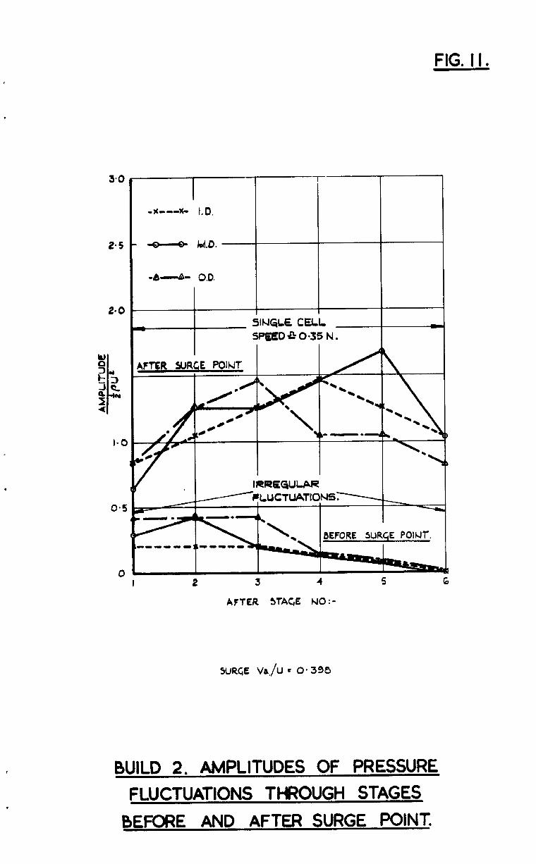
FIG. I I.
I 2 3 4 5 6
AFTER sTAC,E NO:-
5URC,E V&./U = 0.398
BUILD 2, AMPLITUDES OF PRESSURE
FLUCTUATIONS THROUGH STAGES
BEFORE AND AFTER SURGE POINT.
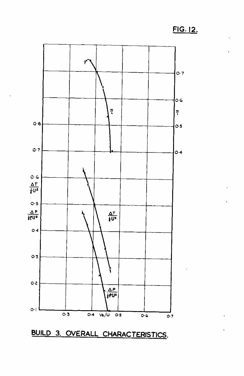
FIG. 12.
c
BUILD 3. OVEl?ALL CHARACTERISTICS.
I I I
NOTE THE CWARACTfRISTIC9 OF
ST&ES 2 TO 4 ARE SMILAR TO THOSt OF §TAC,E 5,
G. 13.
BUILD 3. STAGE CHARACTERISTICS.
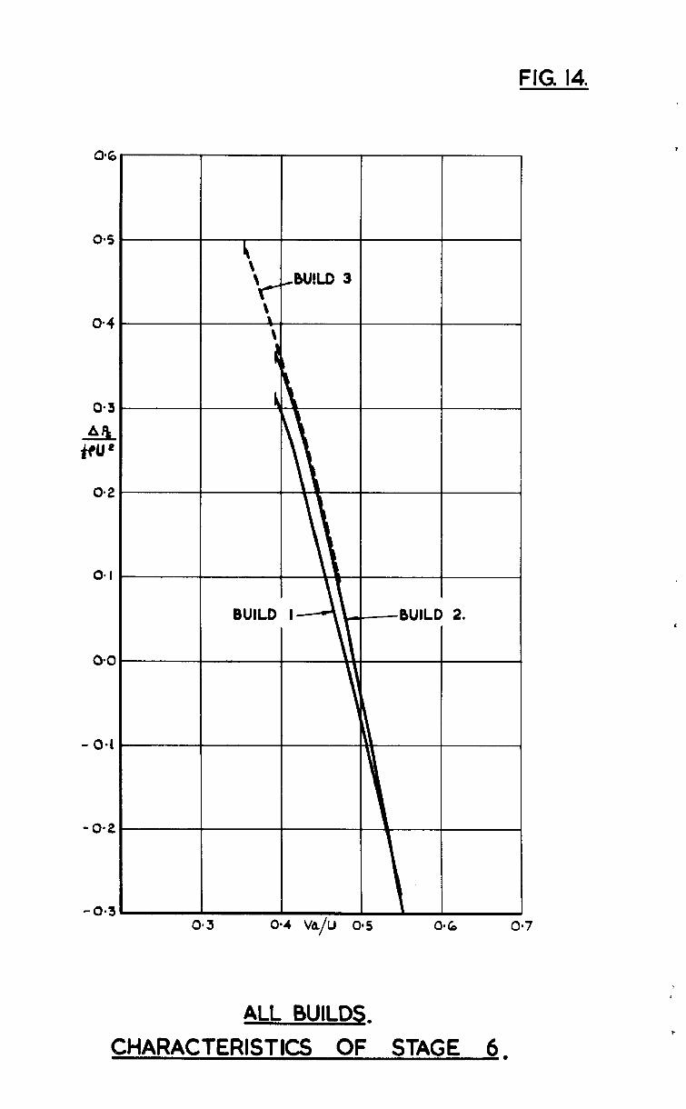
FIG. 14.
0-S
o-4
0.3
aq +eu L
0.2
0.
0.c
- 0.1
-0.2
-0.3 i - I
0*3 O-4 VA/u on5 0.6
ALL BUILDS. CHARACTERISTICS OF STAGE 6,
70
60
&4”
50
40
30
BLADE HEIGHT FROM I.D. INCHE5.
THEORETICAL CURVE
PRIOR To SURGE A7 Va/U - O-358
BUILD 3. AXIAL VELOCITY AND YAW TRAVERSES AFTER STAGE 6
PRIOR TO SURGE.
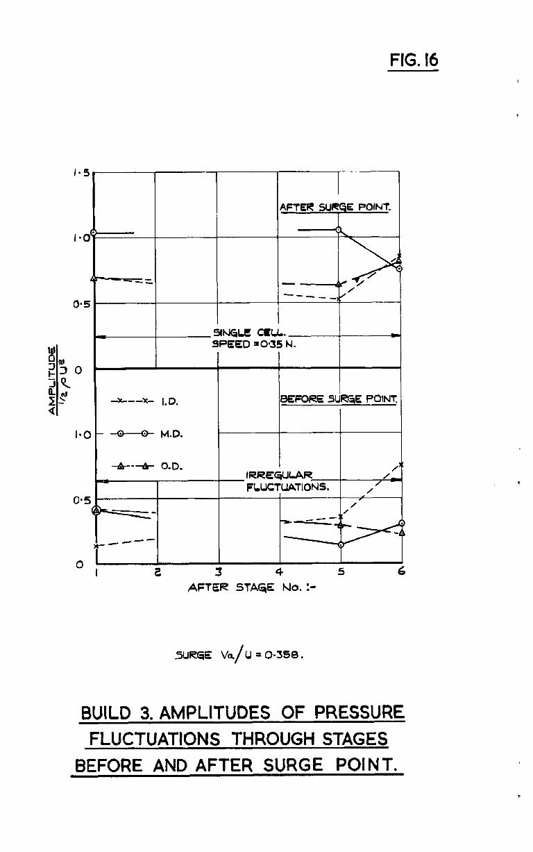
FIG. 16
AFTER SURGE POINT.
-X---X- 1.D . I leEFORE StieE POINT
- . - M.D. .
2 3 4 AFTER STAGE No. :-
5 6
SURGE k/U = O-568.
BUILD 3. AMPLITUDES OF PRESSURE FLUCTUATIONS THROUGH STAGES
BEFORE AND AFTER SURGE POINT. T
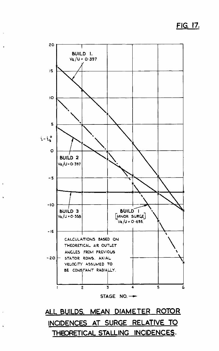
FIG. 17.
5
i-i:
0
-5
-10
-IS
-20
BUILD 3 /a/u = 0.358
I I
CALCULATIONS BASED ON
?-HEORETICAL AIR OUTLET
ANGLE5 FROM PREVIOUS
- STATOR ROWS. AXIAL
VELOCITY A55UMED TO
BE CONSTANT RADIALLY.
2 5 3 4
STAGE NO. --f
6
ALL BUILDS. MEAN DIAMETER ROTOR
INCIDENCES AT SURGE RELATIVE TO THW?ETICAL STALLING INCIDENCES-
C. P. No. 548
0 Crown copyright I%1
Printed and published by HER MAJESTY’S STATIONERY OFFICE
To be purchased from York House, Kingsway, London w.c.2
423 Oxford Street, London w.1 13~ Castle Street, Edinburgh 2
109 St. Mary Street, Cardiff 39Xing Street, Manchester 2
50 Fairfax Street, Bristol 1 2 Edmund Street, Birmin~am 3
80 Chichester Street, Belfast 1 or thruugh any bookseller
s.0. Code No. 23-9012-48
c. P. No. 548