
SIMULATIONS OF ECR PROCESSING SYSTEMS SUSTAINED …
19
UNIVERSITY OF ILLINOIS OPTICAL AND DISCHARGE PHYSICS 25 th IEEE International Conference on Plasma Science Raleigh, North Carolina June 1-4, 1998 IEE98_1 SIMULATIONS OF ECR PROCESSING SYSTEMS SUSTAINED BY AZIMUTHAL MICROWAVE TE(0,n) MODES* * Sponsored by SRC and NSF (ECS94-04133, CTS9412-565) Ron L. Kinder and Mark J. Kushner Department of Electrical & Computer Engineering University of Illinois, Urbana-Champaign e-mail : [email protected] [email protected]
Transcript of SIMULATIONS OF ECR PROCESSING SYSTEMS SUSTAINED …
UNIVERSITY OF ILLINOISOPTICAL AND DISCHARGE PHYSICS
25th IEEE International Conference on Plasma ScienceRaleigh, North Carolina
June 1-4, 1998
IEE98_1
SIMULATIONS OF ECR PROCESSINGSYSTEMS SUSTAINED BY AZIMUTHAL
MICROWAVE TE(0,n) MODES*
* Sponsored by SRC and NSF (ECS94-04133, CTS9412-565)
Ron L. Kinder and Mark J. KushnerDepartment of Electrical & Computer Engineering
University of Illinois, Urbana-Champaigne-mail : [email protected]

UNIVERSITY OF ILLINOISOPTICAL AND DISCHARGE PHYSICS
AGENDA
• Introduction
• Description of Hybrid Plasma Equiptment Model (HPEM)
• Finite Difference Time Domain Module
• Simulation Device Geometry and Operating Conditions
• Simulation Results ( Power, Ionization Rate, Electron Density Distributions )
• Experimental Validation • Results from Parametric Studies
• Conclusions
IEEE98_2

UNIVERSITY OF ILLINOISOPTICAL AND DISCHARGE PHYSICS
INTRODUCTION
• Due to their ability to produce high degrees of ionization at low gas pressures, ECR sources are being developed for downstream etching and deposition, and the production of radicals for surface treatment.
• One advantage of ECR sources is their ability to provide uniformity over large areas. As industry begins to move toward larger wafers, industrial scaleup of these sources is in progress. LAM currently markets a 200 mm deposition tool (scaling to 300 mm). Hitachi has recently announced a 300 mm etch tool.
• The spatial coupling of microwave radiation to the plasma is a concern due to issues related to process uniformity. Studies suggest that certain waveguide electromagnetic mode fields tend to provide better uniformity over larger areas.
• To investigate these issues, we have developed a FDTD simulation for microwave injection and propagation. The FDTD simulation has been incorporated as a module in the 2-dimensional Hydrid Plasma Equipment Model (HPEM).
• Parametric studies have been performed to determine dependence of ion flux uniformity with varying reactor parameters such as mode of excitation, pressure, and power.
IEEE98_3

UNIVERSITY OF ILLINOISOPTICAL AND DISCHARGE PHYSICS
HYBRID PLASMA EQUIPMENT MODEL
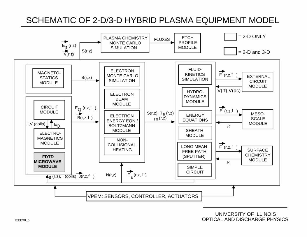
• The base two-dimensional HPEM consists of an electromagnetics module (EMM), an electron energy distribution module (EEDM), and a fluid kinetics simulation (FKS).
• Ion transport was calculated by time integrating the continuity and momentum equations, while electron energy transport was determined by time integrating the electron energy conservation equation.
• Neutral transport was determined by solving the neutral momentum equation.
• An ambipolar approximation was used to solve a Poisson-like equation for the electric potential during early iterations, followed by direct solution of Poisson’s equation.
• Due to the vastly different kinetic time scales for the kinetic reactions compared to convection, such an approximation, allowed for the use of larger time steps, while maintaining stability, during each iteration.
IEEE98_4
UNIVERSITY OF ILLINOISOPTICAL AND DISCHARGE PHYSICS
SCHEMATIC OF 2-D/3-D HYBRID PLASMA EQUIPMENT MODEL
S(r,z)E (r,z)s
v(r,z)
PLASMA CHEMISTRY MONTE CARLO SIMULATION
ETCHPROFILEMODULE
FLUXES
E (r,z, ),
B(r,z, )
Q f
f
ELECTRO-MAGNETICS
MODULE
CIRCUITMODULE
I,V (coils) EQ
S(r,z), T (r,z) (r,z)m
e
FLUID-KINETICS
SIMULATION
HYDRO-DYNAMICSMODULE
ENERGYEQUATIONS
SHEATHMODULE
N(r,z) E (r,z, )s
f(r,z), I (coils), J(r,z, )s f
ELECTRONBEAM
MODULE
ELECTRONMONTE CARLOSIMULATION
ELECTRONENERGY EQN./BOLTZMANN
MODULE
NON-COLLISIONAL
HEATINGLONG MEANFREE PATH(SPUTTER)
SIMPLECIRCUIT
MAGNETO-STATICSMODULE
B(r,z)
= 2-D ONLY
= 2-D and 3-D
EXTERNALCIRCUITMODULE
MESO-SCALE
MODULE
(r,z, )fF
R
(r,z, )fF
V(rf),V(dc)
VPEM: SENSORS, CONTROLLER, ACTUATORS
SURFACECHEMISTRY
MODULE
(r,z, )fF
RFDTD
MICROWAVEMODULE
IEEE98_5

UNIVERSITY OF ILLINOISOPTICAL AND DISCHARGE PHYSICS
DESCRIPTION OF THE FINITE DIFFERENCE TIMEDOMAIN (FDTD) MODEL
IEEE98_6
• The FDTD simulation uses an alternating direction implicit (ADI) scheme. Electromagnetic (EM) fields are calculated using a leap-frog scheme for time integration of Maxwell’s equations, with time steps that are 30% of the Courant limit.
• Plasma dynamics are coupled to the EM fields through a tensor form of Ohm’s law which addresses static B-fields.
i - 1 i i + 1
j + 1
j
j - 1
Eθ
Br
Bz
∆ r
∆ z
∇ x E = - ∂B∂t
∇ x Bµ = σ • E + ε ∂E
∂t
2(1/2)-D Alternating Grid:
σ = q ne M -1
M = α −Bz BθB α −Br
−Bz Br α
α = mq (iω + νm)
where,

UNIVERSITY OF ILLINOISOPTICAL AND DISCHARGE PHYSICS
ABSORBING BOUNDARY CONDITIONS FOR FDTD
• When time domain electromagnetic field equations are solved using finite difference techniques in unbounded space, there must be a method limiting the domain in which the field is computed.
• This is achieved by truncating the mesh and using absorbing boundary conditions at its artificial boundaries to simulate the unbounded surroundings.
• Due to the nature of the 2(1/2)-D alternating direction implicit scheme, boundary conditions using constant gradients for electric and/or magnetic fields cause spurious reflections of the incident waves.
• To remove unwanted reflections, a linearized first order wave equation was imposed as a boundary condition to simulate unbounded surroundings.
IEEE98_7
∂Eθn +1
∂z + ∂Eθ
n
∂z = 1c
∂Eθi, j
∂t + 1c
∂Eθi, j−1
∂t
Linearized First Order Wave Equation:

Magnetic Coils
WaferPumpPort
Gas Ring
DielectricWindow
• Range of Operating Conditions:
• Gas Pressure Range : 0.5 - 5.0 mTorr • Microwave Power : 500 - 1500 Watts • Flow Rates : 5 - 10 sccm • Microwave Field : Circular TE(0,n) modes (2.45 GHz)
• Microwave Field Modes:
TE 01 TE 02
E H
REACTOR GEOMETRY AND OPERATING CONDITIONS
UNIVERSITY OF ILLINOISOPTICAL AND DISCHARGE PHYSICSIEEE98_8

UNIVERSITY OF ILLINOISOPTICAL AND DISCHARGE PHYSICS
MAGNETIC FIELD CONFIGURATION
IEEE98_9
0
30
Radius (cm)20020
626 626
756 756
519519
847 847
911911
0
20 (a)
0
20
300 Height (cm)
(b)
Schematic representation of magnetic fluxfield lines (arrows) and magnetic fieldintensity, in gauss, (contours) inside an ECRprocessing chamber. ECR resonance, for2.45 GHz, occurs at 875 gauss.
• Schematic representation of themagnetic flux density in thedownstream of the reactorchamber. The magnetic flux ispresented (a) without activation ofthe submagnetic coil and (b) withsubmagnetic coil activation.
•

UNIVERSITY OF ILLINOISOPTICAL AND DISCHARGE PHYSICS
POWER DEPOSITION: TE(0,1), TE(0,2)• Power deposition occurs predominantly within 3% of the resonance zone (875 G). Although a small amount of power deposition occurs near the bottom coils due to a second resonance region created by the subcoil. • In the TE(0,2) mode the off axis zero results in two separated regions of power deposition. Such power profiles reflect incident electric field profiles.
IEEE98_10
• N 2, 500 Watts, 1 mTorr, 10 sccm
0
30 Power
(W / cm 3)
1E+01
1E-03
TE(0,2)TE(0,1)
Radius (cm)20020

UNIVERSITY OF ILLINOISOPTICAL AND DISCHARGE PHYSICS
IONIZATION RATES: TE(0,1), TE(0,2)
IEEE98_11
• Ionization rates follow power deposition profiles and are peaked off-axis.
• There is considerable ionization away from the resonance zone due to enhanced confinement of high energy electrons by static magnetic field lines.
Ionization Rate (cm -3 s-1)
1E+16
1E+14
• N 2, 500 Watts, 1 mTorr, 10 sccm
0
30TE(0,2)TE(0,1)
Radius (cm)20020

UNIVERSITY OF ILLINOISOPTICAL AND DISCHARGE PHYSICS
ELECTRON DENSITIES: TE(0,1), TE(0,2)
IEEE98_12
• Due to the enhanced confinement of electrons by magnetic field lines, densities tend to reflect sources. (Note the local maximum in density by the lower coil.)
• To account for anamolous diffusion of electrons across magnetic fields, a small isotropic correction factor was introduced for electron transport.
Electron Density (cm -3)
1.5E+11
1.0E+10
• N 2, 500 Watts, 1 mTorr, 10 sccm
0
30TE(0,2)TE(0,1)
20020Radius (cm)

Radius (cm)0 5 10510
0
10
20
30
40
Experimental(R. Hidaka et al.)Theoretical
N2, 0.5 mTorr, 3 kW
UNIVERSITY OF ILLINOISOPTICAL AND DISCHARGE PHYSICS
ION SATURATION CURRENT VALIDATION
IEEE98_13
• To validate flux to the substrate trends,control experiments conducted at KyushuUniveristy, Japan (R. Hidakaet al., Jpn. J.Appl. Physc. Vol. 32 (1993), pp. 174) weresimulated.
Microwave Power (kW)
1 20
10
20
Experimental(R. Hidaka et al.)
Theoretical
N2, 0.5 mTorr
• Radial distribution of the ion saturationcurrent density in the case of the TE(0,1)mode shows the ion saturation current isuniform within 5% over and 8 inchdiameter.

0.0
1.0 1016
2.0 1016
3.0 1016
4.0 1016
5.0 1016
6.0 1016
400 500 600 700 800 900 1000 1100
Average Ion Flux to the Substrate
Flu
x (
cm
-2 s
-1)
Microwave power (watts)
TE(0,1)
TE(0,2)
UNIVERSITY OF ILLINOISOPTICAL AND DISCHARGE PHYSICS
TOTAL ION FLUX TO SUBSTRATE
IEEE98_14
0.2
0.4
0.6
0.8
1.0
0
• Flux of ions to the substrate reflects their off-axis production rates, and “tieing” of flux to magnetic field lines.
• These results suggest that ion flux uniformities depend more strongly on ionization locations than heating mechanisms.
Radial Ion Flux Profile for TE(0,1) Mode
Radial Ion Flux Profile for TE(0,2) Mode.
0.2
0.4
0.6
0.8
1.0
0

UNIVERSITY OF ILLINOISOPTICAL AND DISCHARGE PHYSICS
ELECTRON DENSITY DISTRIBUTION VERSUS PRESSURE
IEEE98_15
• As pressure is decreased below 2 mTorr, there is shift in the peak density towards the center of the reactor. Such a result implies that the perpendicular diffusion is enhanced at lower pressures.
Pressure = 0.5 mTorr Pressure = 1.0 mTorr Pressure = 10.0 mTorr
• N2, 750 Watts, 10 sccm, TE(0,1) mode
• For the simulations performed the collision frequency was much smaller than the cyclotron frequency. In this regime, the perpendicular diffusion coefficient goes as the collision frequency; Dperp., ~ νm.
• The parallel diffusion coefficient goes as the inverse of the collision frequency; Dpara., ~ 1 / νm.
Density(cm-3)1E+11
5E+09
Density(cm-3)3E+11
1E+10
Density(cm-3)2E+11
1E+10

UNIVERSITY OF ILLINOISOPTICAL AND DISCHARGE PHYSICS
TOTAL ION FLUX TO THE SUBSTRATE
IEEE98_16
• The ion flux profile, at the substrate, reflects the shift in peak density at lower pressures.
• The magnitude of the average ion flux, above 1 mTorr, follows an inverse pressure dependence.
• At higher pressures, the ion flux profile becomes increasingly uniform due to enhanced cross field diffusion.
Radius (cm)
10
1
0.5
100
Ion Flux to Substrate [5.0E+16/cm 2-s]
• N2, 750 Watts, 10 sccm, TE(0,1) mode
0.0
5.0 1015
1.0 1016
1.5 1016
2.0 1016
2.5 1016
3.0 1016
3.5 1016
4.0 1016
0.0
20.0
40.0
60.0
80.0
100.0
0.10 1.0 10 102
Ion Flux and Uniformity to the Substrate
Ave
rage
Flu
x (c
m
-2s-1
) Percent U
niformity (%
)
Pressure (mTorr)
0.0
0.20
0.40
0.60
0.80
1.0
0.10 1.0 10 102
Average Ion Flux x Flux Uniformity
Eff
icie
ncy
Pressure (mTorr)

UNIVERSITY OF ILLINOISOPTICAL AND DISCHARGE PHYSICS
EFFECTS OF COLLISION FREQUENCYON CROSS FIELD DIFFUSION
IEEE98_17
• At pressures below 2 mTorr, the electron temperature increases dramatically due to enhanced power coupling of the incident wave to the plasma. • In the low pressure regime, the high temperature significantly affects the momentum transfer rate coefficient, thereby increasing the collision frequency. At higher pressures the collision frequency depends on the neutral gas density.
• Such results indicate that there exists an optimal pressure for maximizing ion flux and flux uniformity to the substrate.
• N2, 750 Watts, 10 sccm, TE(0,1) mode
0.0
2.0
4.0
6.0
8.0
10
0.10 1.0 10 102
Average Electron Temperature
Tem
pera
ture
(eV)
Pressure (mTorr)
0
2 10-7
4 10-7
6 10-7
8 10-7
1 10-6
0
2 1014
4 1014
6 1014
8 1014
1 1015
0.10 1.0 10 102
Momentum Transfer Rate and Gas Density
Ave
rage
Mom
entu
m T
rans
fer
Rat
e C
oeffi
cien
t (cm
-3s-1
)
Neutral G
as Density (cm
-3)
Pressure (mTorr)
TemperatureDependence
PressureDependence

UNIVERSITY OF ILLINOISOPTICAL AND DISCHARGE PHYSICS
CONCLUSIONS: ECR SOURCE MODELING
IEEE98_18
• Simulation of such ECR systems indicate that magnetic field configuration, electromagnetic waveguide modes, and location of resonance strongly influence flux profiles to the substrate.
• Studies suggest that uniform fluxes at the substrate may require a power profile peaked off-axis.
• Lower order TE(0,n) modes tends to produce higher ion fluxes to the substrate, while higher order modes allow for greater uniformity across the substrate.
• At low pressures, < 1 mTorr, plasma dynamics depend highly on electron temperature. Cross field ion diffusion is enhanced by an increased momentum transfer rate coefficient.
• While at higher pressures, the electron temperature falls off due to thermalization and a decreasing efficiency in power coupling between the incident wave and the plasma. This leads to a cross field diffusion that is sensitive to neutral gas densities.
• Studies indicate that there exists an optimal pressure for maximum flux to the substrate and maximum flux uniformity.