SERVO FEED OPERATING INSTRUCTIONS - Rapid-Air · SERVO FEED OPERATING INSTRUCTIONS ... 100D...
37
RAPID-AIR CORPORATION 4601 KISHWAUKEE ST. • ROCKFORD, IL 61109-2925 Phone: (815) 397-2578 • Fax: (815) 398-3887 • Web Site: www.rapidair.com SERVO FEED OPERATING INSTRUCTIONS MODELS 100C SERIES (INCLUDES 100D SERIES)
Transcript of SERVO FEED OPERATING INSTRUCTIONS - Rapid-Air · SERVO FEED OPERATING INSTRUCTIONS ... 100D...

��
Rapid-aiR coRpoRation4601 KishwauKee st. • RocKfoRd, iL 61109-2925
phone: (815) 397-2578 • fax: (815) 398-3887 • web site: www.rapidair.com
SERVO FEEDOPERATING INSTRUCTIONS
ModeLs100c seRies
(incLudes 100d seRies)
��
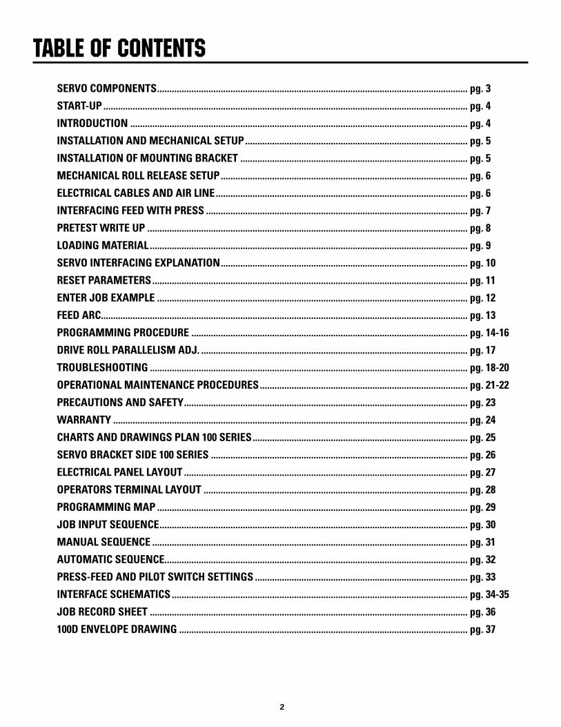
SERVO COMPONENTS ............................................................................................................................... pg. 3
START-UP ..................................................................................................................................................... pg. 4
INTRODUCTION .......................................................................................................................................... pg. 4
INSTALLATION AND MECHANICAL SETUP ........................................................................................... pg. 5
INSTALLATION OF MOUNTING BRACKET ............................................................................................. pg. 5
MECHANICAL ROLL RELEASE SETUP ..................................................................................................... pg. 6
ELECTRICAL CABLES AND AIR LINE ....................................................................................................... pg. 6
INTERFACING FEED WITH PRESS ........................................................................................................... pg. 7
PRETEST WRITE UP ................................................................................................................................... pg. 8
LOADING MATERIAL .................................................................................................................................. pg. 9
SERVO INTERFACING EXPLANATION ..................................................................................................... pg. 10
RESET PARAMETERS ................................................................................................................................. pg. 11
ENTER JOB EXAMPLE ............................................................................................................................... pg. 12
FEED ARC...................................................................................................................................................... pg. 13
PROGRAMMING PROCEDURE ................................................................................................................. pg. 14-16
DRIVE ROLL PARALLELISM ADJ. ............................................................................................................. pg. 17
TROUBLESHOOTING .................................................................................................................................. pg. 18-20
OPERATIONAL MAINTENANCE PROCEDURES ..................................................................................... pg. 21-22
PRECAUTIONS AND SAFETY .................................................................................................................... pg. 23
WARRANTY ................................................................................................................................................. pg. 24
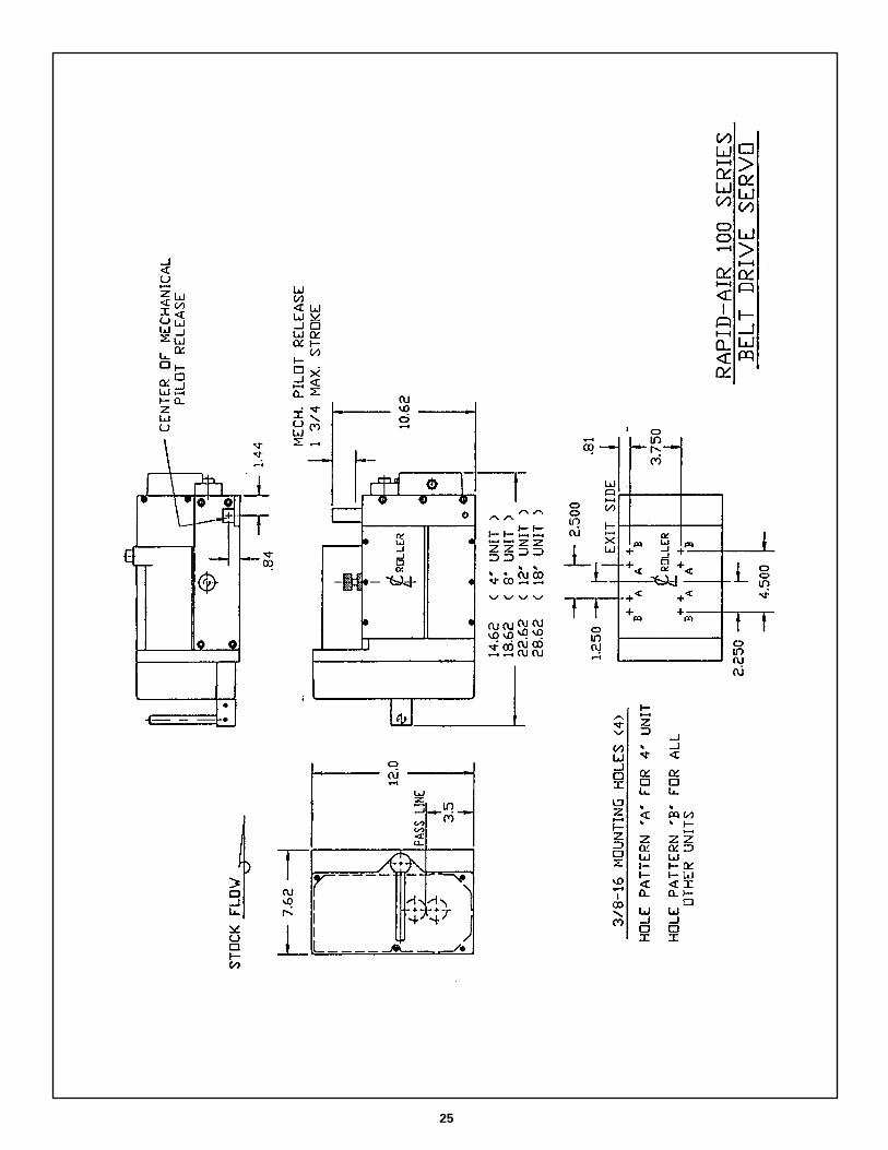
CHARTS AND DRAWINGS PLAN 100 SERIES ........................................................................................ pg. 25
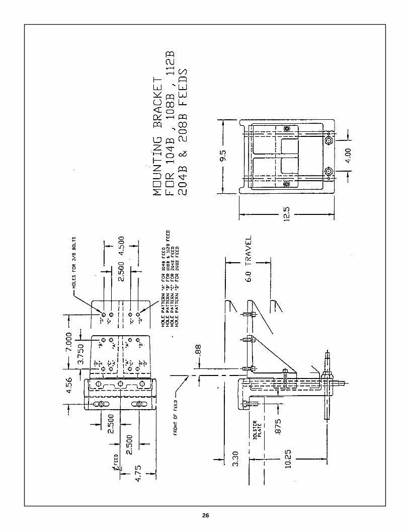
SERVO BRACKET SIDE 100 SERIES ......................................................................................................... pg. 26
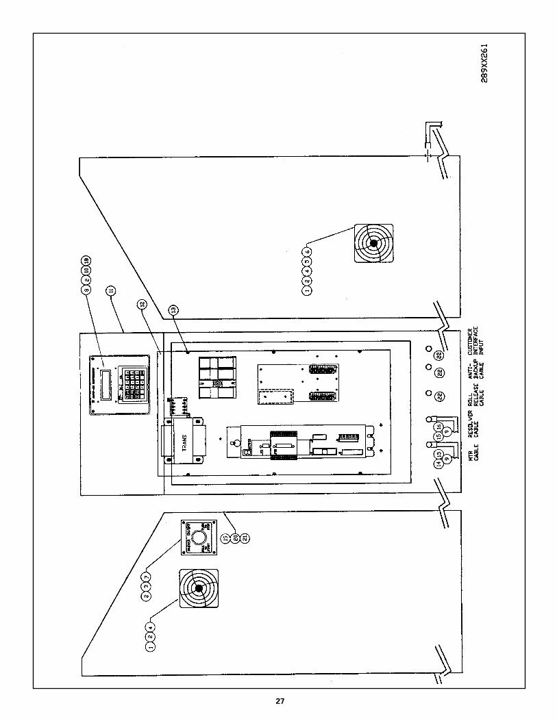
ELECTRICAL PANEL LAYOUT .................................................................................................................... pg. 27
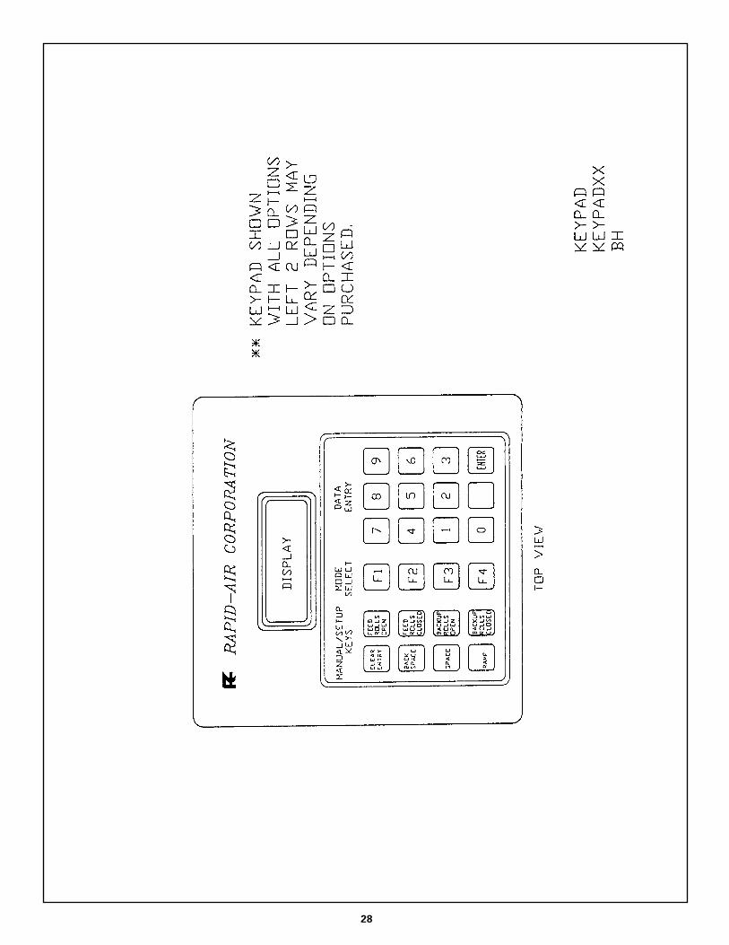
OPERATORS TERMINAL LAYOUT ............................................................................................................ pg. 28
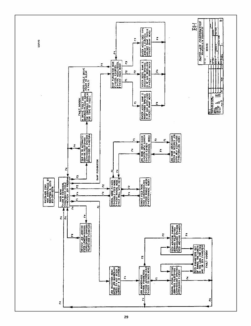
PROGRAMMING MAP ............................................................................................................................... pg. 29
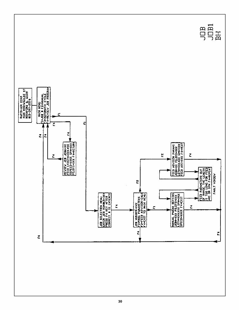
JOB INPUT SEQUENCE .............................................................................................................................. pg. 30
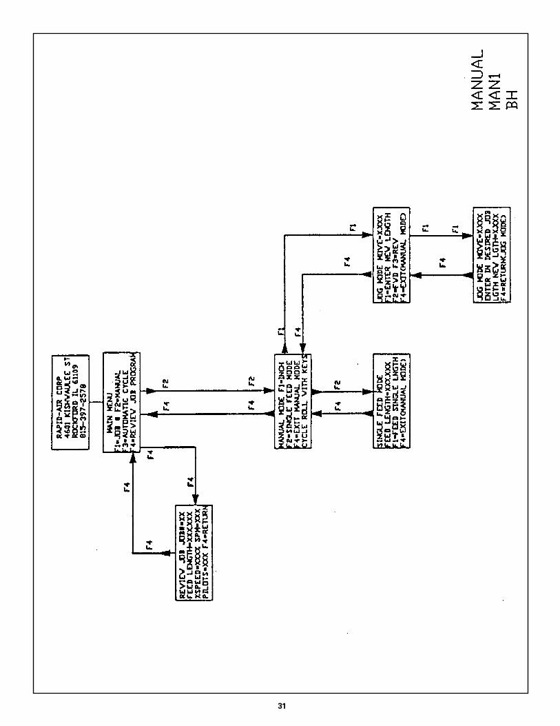
MANUAL SEQUENCE ................................................................................................................................. pg. 31
AUTOMATIC SEQUENCE............................................................................................................................ pg. 32
PRESS-FEED AND PILOT SWITCH SETTINGS ....................................................................................... pg. 33
INTERFACE SCHEMATICS ......................................................................................................................... pg. 34-35
JOB RECORD SHEET .................................................................................................................................. pg. 36
100D ENVELOPE DRAWING ...................................................................................................................... pg. 37
TAblE OF CONTENTS
��
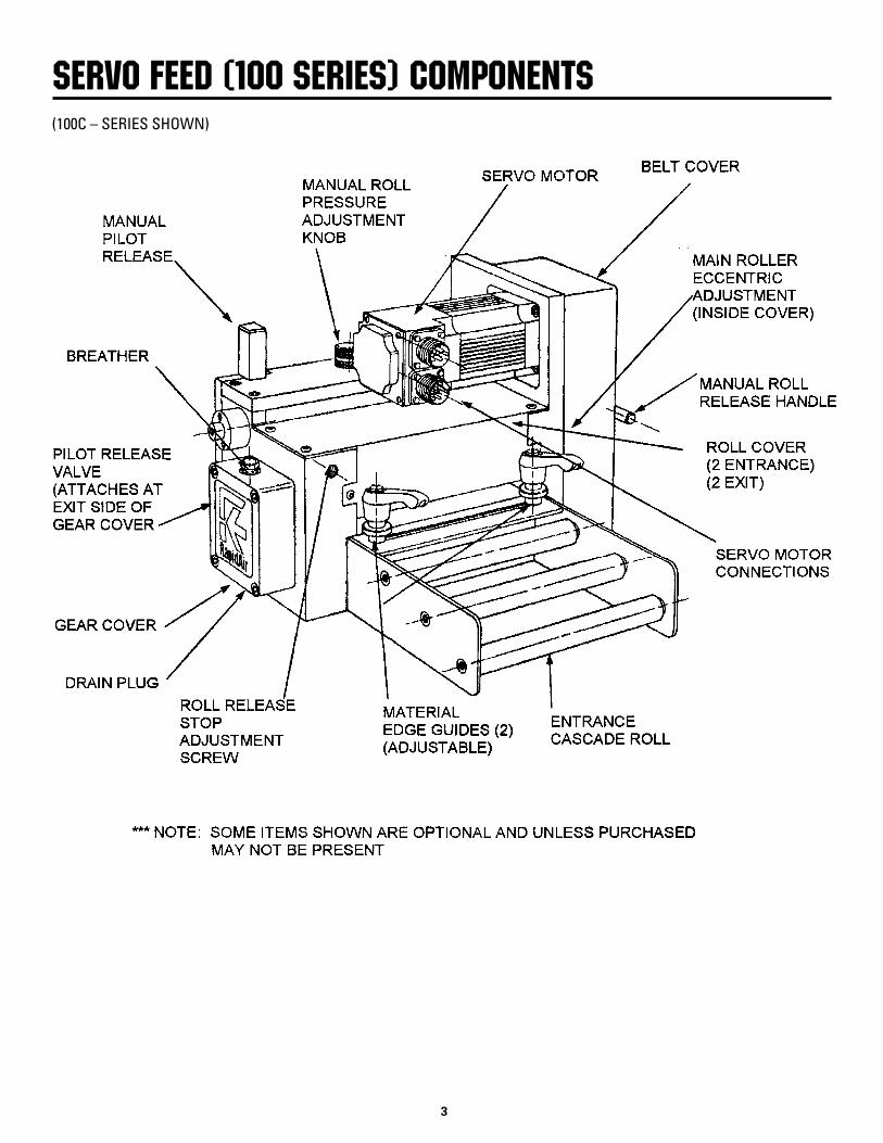
SERVO FEED (100 SERIES) COmPONENTS(100C – SERIES SHOWN)
��
Congratulations on purchasing a Rapid-Air Servo. Not only did you receive a complete servo unit but also telephone support by one of our engineering staff to guide you on using the new servo to its maximum capability.
In order to maximize your learning time and trouble shoot any interface problems, we would like
START-UP AND INTRODUCTION
Rapid-Air Start-Up Section (100C & D Series Servo)to request that the following itemsbe complete before calling us.
1. Servo unit should be completely installed and aligned to a die on the press.
2. 120 vac electrical wiring should be in place and unit turned on.
3. All interface switches should
be wired and tested.
4. Air if needed should be connected and ready to be used.
5. All servo interface questions should first be directed to your distributor, then to Rapid-Air. Please call 815-397-2578 and ask to have these questions directed to the proper personnel.
The Rapid-Air servo feed carries with it the quality and reliability you have grown to expect from a Rapid-Air product. The motion control system is a programmable industrial com-puter and this advanced technology combined with a highly engineered precision roll feed, is an unchallenged combination in the press industry.
The compact mechanical package, direct coupled with a brushless servo drive motor, offers response and feed accuracy unparalleled in any other powered roll feed. Operator interface is so simplified, a typical setup person can have the servo feed programmed and running in a matter of minutes.
IntroductionA step by step prompt on the four line 80 character display asks simple questions of the operator. Entry of feed length, strokes per minute, % maximum speed and pilot are all that is required for a new setup. Routine jobs can be stored, recalled, changed and saved or run with a simple 2 digit job number entry. Up to 99 jobs may be stored and recalled at will.
Operator programmed feed length, up to 999.999 inches and % max speed selection along with full jog features, allow the operator to thread thematerial and inch it into position. The inch feature enables the operator to jog the servo feed forward or reverse
at a slow rate. He can select jog to length or jog continuous to aid him in the threading up of material.
The precision mechanical roll feed unit has been designed for compact-ness, ease of setup and installation. A 120 VAC receptacle is all that is required of the customer. Two cables with twist lock plugs are supplied with the control and need only be connected to the proper locations on the motor. The electrical controls are housed in a small cabinet which should be mounted close to the press working area. The operator keypad and display are mounted on top of the control area.

��
The shipping container should contain: 1 Mechanical Servo Feed: –Standard 1 Console Complete: –Standard 1 Cascade Assembly: –Optional (100 Series) 1 Servo Mounting Bracket: –Optional 1 Guide Support Assembly: –Optional
If a mounting bracket was purchased then it should be installed at this time. There are mounting bracket prints in the back of the manual for hole location dimensions and a bracket mounting instruction section can be found later in this section.
INSTAllATION AND mEChANICAl SET-UP
Installation and Mechanical Set-Up of Servo FeedIf a mounting bracket was not purchased then the feed should be positioned with the centerline of the drive roller in line with the centerline of the die entrance and at the proper pass line height to the die. Aligning the feed to the die (Parallelism) is very important to the accuracy of the feed. Drag due to misalignment can cause short feeds and servo faults.
If the feed is positioned as such that the material has to move unsupported from the exit side of the feed to the die and the material being moved is
allowed to droop or buckle during a move, a short feed can occur. A guide should then be built between the feed and the die to solve this problem.
The following chart lists the servo size with the proper bolt size.
SERVO BOLT QUANTITY Series 100 All 3/8-16 4
The servo mounting bolts should not penetrate into the servo body by more than .625”.
The cast mounting bracket is available for mounting the servo feed directly to the bolster plate of the press. There are several sets of mounting holes in the bracket to afford the setup person an efficient means of mounting the bracket. Mounting holes are located on the top and front for securing the bracket firmly. It is very important that the servo bracket and the servo feed be secured and not allowed to float or vibrate.
NOTE: It is very important that the end of the bolster plate, where the servo feed is to be mounted, be perpendicular to the top surface of the bolster plate within +-.005 to as-sure the servo feed will be aligned for proper feeding.
Installation and Mechanical Set-Up of Mounting BracketAlign the servo feed bracket with thecenter line of the bolster plate and trans-fer the mounting holes on the top face. There are two 1/2” holes on this bracket.
Once the bracket has been aligned and secured to the bolster plate, the servo feed can now be put in place. The slotted holes in the mounting bracket allow for accurate alignment of the servo feed in the x – y axis. There is an elevating screw to position the servo feed to the proper tooling pass line height.
When the servo feed has been aligned and mounted to the bracket, loosen the elevator locking screws and position the servo to match the tooling pass line height. This is accomplished by turning the adjusting
screw provided. When the servo is correctly positioned, tighten the elevator locking screws to prevent the unit from moving. There are 2 locking screws on the this bracket.
The unit is now assembled and the next step will be to attach the electrical and air, if used, to the servo feed unit.
Material alignment is critical. The servo feed rolls are so precise that they will move the material in what-ever direction that they are presented to the die. The feed and die must be in line and square to one another. The servo feed does not have the power of a press driven roll feed so the feed will fault out if misaligned. This is a good warning and if corrected could result in better tool life.
��
All the 100 feeds have an optional mechanical pilot release. If the mechanical pilot release is used, (we recommend this for press speeds faster than 250 SPM) then a bracket has to be manufactured and attached to the press ram to actuate the pilot release mechanism.
NOTE: The roll release height adjustment screw should be backed off all the way to prevent jamming when using the mechanical release.
The bracket should be made adjust-able for tuning to the press position in which the roll release should occur. Some attention should be given to the bracket stroke length so that the
ROll RElEASE SET-UP AND CAblING
Mechanical Roll Release Set-Uprelease mechanism is not jammed into the feed during the press stroke.
The 100 series pilot release actuator has a 1” stroke to full open with an additional .750” overtravel before bottoming out.
We do not offer any manufactured bracket to assist you because there are as many combinations for stroke and clearance as there are presses manufactured today.
We do, however, ask that the bracket be designed to withstand considerable resistance as the mechanism has to defeat the roller pressure spring force.
OPTIONAL MANUAL PILOT RELEASE The optional manual pilot release should be ordered at the time of purchase but can be added at a later date. Rapid-Air would like to perform the installation if at all possible.
OPTIONAL ELECTRIC PILOT RELEASE The optional pilot release pack-age consists of a valve, fitting, relay and solenoid cable. A switch signal from the press has to be wired to the control panel and an air line has to be connected to the valve from the main shop air. The relay and solenoid cable will have to be mounted and wired in the electric cabinet if it is to be used with the program.
The electrical control enclosure is shipped completely ready to be con-nected to the mechanical feed. Con-nected to the bottom of the enclosure are (2) cables with keyed screw type connectors for connection to the motor.
Electrical Cables and Air LinePosition the electrical enclosure at a convenient location near the mechan-ical feed and attach the cables. The motor cables are easily identifiable by the amount of pins in the plugs.
An air line must be connected from the shop air to the air inlet of the
servo feed. The air should be at least 80 PSI continuous and should be dry fil-tered and lightly lubricated for the best operation of the servo feed. The air inlet on the servo feed is a 3/8-18 NPT pipe tap. The minimum air line size requirement is 1/2” ID hose. - (2 CFM)

��
The Servo Drive unit is a slave to the press therefore it needs a command from the press to operate in the automatic mode.
The command is in the form of a normally open contact from a limit switch, cam switch or an electronic feed interface device that can be programmed.
The contact should be commanded or activated at 270 degrees of the press stroke or when the tooling is clear of the material and released or turned off at around 350 degrees of the press stroke. The significance of the release position is to insure that the feed switch is released with the press top stopped. Once the program senses a closure of the feed input, it will command a move and will complete the move regardless of the switch position.
The air operated pilot release also has to have a signal input to
INTERFACING FEED wITh PRESS
Interfacing Servo Feed With A Pressoperate. The pilot signal should be set to turn on when the point of the pilot is entering the hole. This signal them commands air roll release to raise and release the material, letting the pin pull the material forward into position. The release should be then commanded to turn off at approximately 180 degrees letting the rollers return to a holding position for the next move.
The roll release stop adjustment screw is located at the entrance of the feed. (See drawing for your servo). The screw is used to limit the travel of the roller during release. Adjustment may be necessary if using air pilot release at a somewhat high speed with the pilot release deactivating and feed switchactivating at a close proximity with each other in degrees of press stroke. To adjust, insert material into the feed, lower rolls, adjust screw, using 3/16 hex wrench, to full in. Release rolls and adjust screw so the material is
free to be pulled in by the pilot pin. The adjustment is now complete. (NOTE: This adjustment does limit the manual roll release travel. If this causes a problem back off the adjustment a little.)
The schematic in the back of this manual points out the switch or contact connections for wiring the interface. Locate the feed input and wire per print. This input is brought down to a terminal strip for your convenience. The feed input number is (J52)TB1-2) and the pilot input number is (J52)TB1-4).
This completes the initial setup of the servo feed to the press or other device. The servo is now ready to run as intended.
If more complete interfacing is needed, please refer to the section (interfacing ) in this manual for an explanation of inputs and ouputs available.
��
Now that your servo feed unit has been mounted and the cables have been attached, you can proceed with testing the unit. The first step is to turn on the main disconnect switch on the electrical enclosure. Next, at the operator’s console, turn on the on-off switch. The button should illuminate to indicate that there is power to the system.
The drive performs an initiate sequence to check it’s internal program. At this time the display should show the Rapid-Air screen for 5 seconds before starting the main setup program. If you are comfortable with programming a job then continue; if not, please refer to the “Programming Procedure” located in this manual.
Follow the programming sequence for the operators terminal to input parameters into job storage. Your servo feed has been fully tested before it was shipped to your facility
PRETEST wRITE UP
Pretest For Servo Feed And Press Without Materialand this procedure is merely a test to insure that all functions are still functional and the cables are properly seated.
Once you have programmed the required parameters, select the manual mode of operation. If you are using air, check that the main air is at least 80 PSI. Open and close the feed rolls electrically and or manually. Visually inspect that the rolls open and close as you press the appropriate keys on the keypad or when using the manual levers.
Select the “inch” function (F2 on keypad) on the manual mode screen. Visually check that the rolls rotate both forward and reverse with the corresponding key. The speed is preset to creep the rolls at a slow speed for manual positioning of the material.
CAUTION: Do not attempt to place your fingers or any foreign
material into the rolls. Injury to the operator or damage to the servo rolls could result.
After you have verified that the rolls and air logic are operational, you can experiment with the single cycle moves. The procedure is outlined in the programming section of this manual.
Now you can cycle the press and watch the rolls to verify that the signal from the press window switch signal is functional and actuating at the proper time.
After all the checks have been made and you feel comfortable with the programming of the servo controller, place the servo in automatic mode. Now cycle the press in either the inch, single stroke or continous run. The servo feed should react upon the closure of the press window and signal and simulate a feed progression of material.
��
Upon the satisfactory completion of all the tests, you should be ready to load a strip of material into the servo feed.
Step number one is to select the manual mode of operation on the operators console. Then choose “Operate Rolls”. This will allow you to open the feed rolls and antibackup rolls to accept the material. You could also open the rolls manually by lifting the lever mounted on the side of the servo feed. Position the leading edge of the material with the center of the material near the center of the entry rolls, adjust the edge guides on the cascade rolls to the proper width setting. Open the feed rolls and hand
lOADING mATERIAl
Loading Material Into The Servo Feedfeed the material into the servo unit until it protrudes out of the feed rolls and starts into the guide on the press, then close the feed rolls.
Check the roller force pressure to be sure that there is enough pressure to prevent slippage but not too much to induce camber into the material. The pressure setting is the amount of force necessary to move the material into the press at the speed and feed programmed. You may find it necessary to readjust the force as you finalize the setup procedure. The amount of force needed will vary depending on the width and type of material being fed. Make a note of
the final setting to aid in the setup of the servo feed the next time the same material is run.
You are now ready to begin testing the complete system under power. To check the progression, cycle the press in the single cycle mode with the servo feed in the automatic mode. If the progression is correct, no fur-ther adjustments are necessary. If the progression is either short or long, go to the troubleshooting chart and per-form the sequences described there for inaccurate feeding, once the feed progression has been accuratelly set and the repeatability is satisfactory, you are ready for full automatic mode.
��0
A. TAUT STOCK INPUT (J52)TB1-6) This is a normally open contact from a switch or device that monitors the loop of material prior to the servo feed. When the material reaches a point that it trips the switch, a taut stock has been reached. This input, when received, immediately drops the automatic which stops the feed in progress. The material should be repositioned in the die before restarting the automatic sequence as the progression was lost when the taut stock occurred. This input also could be used as a “No Stock” switch that would monitor whether or not there is material available to feed.
B. ENABLE INPUT (J4)PIN 5 & 6) The enable input is shipped from the factory, jumpered, so that the Pac-Sci unit is ready to work after the initial-ization procedure is complete. If it is desired that the servo controls are not functional until other equipment or safety source is activated before the servo can function then a normally open contact can be interfaced to this input. If at any time during the feed cycle the input changes state then the feed will stop at this position. If feeding stock, the referance will be lost and the stock will have to be manually repositioned to the correct location. The automatic cycle will be dropped and have to be restarted.
C. ENABLE OUPUT (J52)TB2-15) This output must be tied to a solid
SERVO INTERFACING
Servo Interfacing Explanationstate relay to interface to the ouside world. The solid state relay must have a D.C. coil and should have a rating of 3-30 VDC. The Rapid-Air #69100165 is recommended for this application. This output is high when-ever the enabled input is activated.
D. END OF FEED OUTPUT (J52)TB2-13) This output must be tied to a solid state relay to interface to the outside world. The solid state relay must have a D.C. coil and should have a rating of 3-30 VDC. The Rapid-Air #69100165 is recommended for this application. This output goes high at the end of every feed and stays high for programmed amount of time before going low. To program the time, with the menu display on, push the period on the keypad - follow the instructions and enter the time in milli-seconds. The time entered will add to the total feed cycle time and if programmed to last longer than the time from the actual end of feed and the actual tripping of the feed switch then the program will not see the feed switch being tripped, you will then get two hits per feed.
E. AUTOMATIC OUTPUT (J52)TB2-11) This output must be tied to a solid state relay to interface to the outside world. The solid state relay must have a D.C. coil and should have a rating of 3-30 VDC. The Rapid-Air #69100165 is recommended for this application. This output goes high whenever automatic is selected on
the program panel. Any faults will cause the automatic output to go low.
F. STANDARD PROGRAM - DATA INSTRUMENTS INTERFACE (J52)TB1-14) With the jumper in place, the standard program is active. Remove the jumper, recycle power and the Data Instruments program is active. Only the manual mode will work with the keys at this time.
G. KEYPAD AND DISPLAY INTERFACE (RS232 PORT) The keypad/display is the interface between the operator and the resi-dent program. The Pacific Scientific drive is purchased with a great many capabilities, none of which can be used unless a program is written to utilize these capabilities. Rapid-Air put a great deal of time into making a program that is user friendly and yet gets the job done efficiently. We took all the questions and constructive criticism and came up with a program that would cover all the applications, yet be easy to interface and program by a customer. If an operator reads the programming procedure in this manual and then reads the screen parameters listed as they are dis-played and acts on them by inputting data as needed, the servo can be up and running in a very short time. 1. Select a job number. 2. Input or review parameter for that job number. 3. Thread up material in manual mode. 4. If properly interfaced, go into automatic mode.
���
The reset job parameters routing should be used with special caution. We incorporated it as a user function for two reasons.
The first reason is if a problem caused the displayed parameters to be garbled because of a program glitch, then by resetting the job parameters the problem could be cleared.
The second reason is if there were a number of different jobs in memory that were no longer required, then by resetting the job parameters, all the job numbers would be reset to their default values, which includes putting all zeros in the feed length and strokes per minute area of the program.
RESET PARAmETERS
Reset Job ParametersCAUTION!! CAUTION!! CAUTION!! Keep a hard copy record of program numbers and data associated with them for reference if needed. If this function is used in a way other than what it was designed for then all previous data is lost and cannot be recovered.
To enter this function, turn off the program by depressing the master stop button. Turn on the program again and push and hold the “clear entry” key, once the program has started the following screen will be displayed.
**DEFAULT VALUE SETUP PRESS F1 TO RESET TO DEFAULT VALUES, PRESS F4 TO IGNORE CHANGES
**Once F1 has been pressed then all data that had been entered will be reset.
PROGRAM NUMBER DISPLAY Each servo unit that is shipped has a program number assigned to it. If a problem occurs and cannot be solved by reloading the program then you will be asked the program number associated with this servo. To view the program number, press and hold the “back space” key during the power up sequence. The program number will be displayed for about 30 seconds. Please find and write down the program number in case it is needed in the future.
���
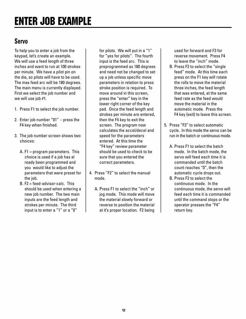
To help you to enter a job from the keypad, let’s create an example. We will use a feed length of three inches and want to run at 100 strokes per minute. We have a pilot pin on the die, so pilots will have to be used. The max feed arc will be 180 degrees. The main menu is currently displayed. First we select the job number and we will use job #1.
1. Press F1 to select the job number.
2. Enter job number “01” – press the F4 key when finished.
3. The job number screen shows two choices:
A. F1 = program parameters. This choice is used if a job has al ready been programmed and you would like to adjust the parameters that were preset for the job. B. F2 = feed-advisor-calc. This should be used when entering a new job number. The two main inputs are the feed length and strokes per minute. The third input is to enter a “1” or a “0”
ENTER jOb ExAmPlE
Servo for pilots. We will put in a “1” for “yes for pilots”. The fourth input is the feed arc. This is preprogrammed as 180 degrees and need not be changed to set up a job unless specific move parameters in relation to press stroke position is required. To move around in this screen, press the “enter” key in the lower right corner of the key pad. Once the feed length and strokes per minute are entered, then the F4 key to exit the screen. The program now calculates the accel/decel and speed for the parameters entered. At this time the “F4 key” review parameter should be used to check to be sure that you entered the correct parameters.
4. Press “F2” to select the manual mode. A. Press F1 to select the “inch” or jog mode. This mode will move the material slowly forward or reverse to position the material at it’s proper location. F2 being
used for forward and F3 for reverse movement. Press F4 to leave the “inch” mode. B. Press F2 to select the “single feed” mode. At this time each press on the F1 key will rotate the rolls to move the material three inches, the feed length that was entered, at the same feed rate as the feed would move the material in the automatic mode. Press the F4 key {exit} to leave this screen.
5. Press “F3” to select automatic cycle. In this mode the servo can be run in the batch or continuous mode. A. Press F1 to select the batch mode. In the batch mode, the servo will feed each time it is commanded until the batch count reaches “0”, then the automatic cycle drops out. B. Press F2 to select the continuous mode. In the continuous mode, the servo will feed each time it is commanded until the command stops or the operator presses the “F4” return key.

���
To explain how the “feed arc” is related to the servo feed calculation, we must first explain what the feed arc is in relation to a press.
The press has a die that has two halves. The lower half is stationary and the top half is moveable in an up and down motion which is one cycle from the full open to the full closed to the full open again. The component that makes all of this happen is named “crankshaft”. The crankshaft makes a 360 degree revolution for one cycle of the die from open to close to open again. When the die is fully open, the crankshaft would be at “0” degree position. When the die is fully closed the crankshaft is at 180 degrees or one-half of a revolution.
We ask that a switch be set at 270 degrees to activate the feed because
Feed Arc Relationshipat this position, the die is completely clear of the material. This is also a good starting point to explain the “feed arc” portion of the auto calculation in the Rapid Air program.
If the feed input switch was tripped at 270 degrees of the total revolution of the crankshaft and the arc calcula-tion was 180 degrees then the servo feed would complete it’s feed by 90 degrees of the press cycle or 180 degrees past the 270 degree mark.
The feed arc could be set at 90 degrees so the feed cycle would be complete by 360 degrees or when the press was at the top of the stroke.
The feed arc could be set at 270 degrees so the feed cycle would be complete when the press was at 180 degrees. This example would not
work if the feed cycle started at 270 degrees as the feed would still be trying to move the material when the die was closed or together. To use a 270 degree feed arc the feed would have to start at 230 degrees or 240 degrees to be finished moving the material before the die was closed or together. This example could not be possible if the die had pilot pins installed in it for precise locating of the stamped part. The cam switch drawing in the back of the manual will help you visualize the above feed arc explanation.
In essence, the larger the feed arc number up to 270 degrees, the lower the acceleration/deceleration rate. The smaller the feed arc the higher the acceleration/deceleration rate and the fewer strokes per minute for a given feed length.
FEED ARC
���
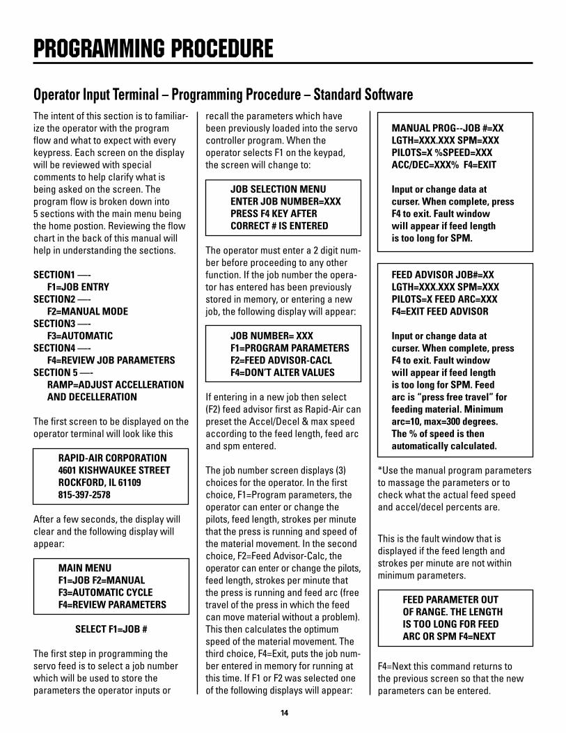
Operator Input Terminal – Programming Procedure – Standard Software
PROGRAmmING PROCEDURE
The intent of this section is to familiar-ize the operator with the program flow and what to expect with every keypress. Each screen on the display will be reviewed with special comments to help clarify what is being asked on the screen. The program flow is broken down into 5 sections with the main menu being the home postion. Reviewing the flow chart in the back of this manual will help in understanding the sections.
SECTION1 —- F1=JOB ENTRY SECTION2 —- F2=MANUAL MODE SECTION3 —- F3=AUTOMATIC SECTION4 —- F4=REVIEW JOB PARAMETERS SECTION 5 —- RAMP=ADJUST ACCELLERATION AND DECELLERATION
The first screen to be displayed on the operator terminal will look like this
RAPID-AIR CORPORATION 4601 KISHWAUKEE STREET ROCKFORD, IL 61109 815-397-2578
After a few seconds, the display will clear and the following display will appear:
MAIN MENU F1=JOB F2=MANUAL F3=AUTOMATIC CYCLE F4=REVIEW PARAMETERS
SELECT F1=JOB #
The first step in programming the servo feed is to select a job number which will be used to store the parameters the operator inputs or
recall the parameters which have been previously loaded into the servo controller program. When the operator selects F1 on the keypad, the screen will change to:
JOB SELECTION MENU ENTER JOB NUMBER=XXX PRESS F4 KEY AFTER CORRECT # IS ENTERED
The operator must enter a 2 digit num-ber before proceeding to any other function. If the job number the opera-tor has entered has been previously stored in memory, or entering a new job, the following display will appear:
JOB NUMBER= XXX F1=PROGRAM PARAMETERS F2=FEED ADVISOR-CACL F4=DON’T ALTER VALUES
If entering in a new job then select (F2) feed advisor first as Rapid-Air can preset the Accel/Decel & max speed according to the feed length, feed arc and spm entered.
The job number screen displays (3) choices for the operator. In the first choice, F1=Program parameters, the operator can enter or change the pilots, feed length, strokes per minute that the press is running and speed of the material movement. In the second choice, F2=Feed Advisor-Calc, the operator can enter or change the pilots, feed length, strokes per minute that the press is running and feed arc (free travel of the press in which the feed can move material without a problem). This then calculates the optimum speed of the material movement. The third choice, F4=Exit, puts the job num-ber entered in memory for running at this time. If F1 or F2 was selected one of the following displays will appear:
MANUAL PROG--JOB #=XX LGTH=XXX.XXX SPM=XXX PILOTS=X %SPEED=XXX ACC/DEC=XXX% F4=EXIT
Input or change data at curser. When complete, press F4 to exit. Fault window will appear if feed length is too long for SPM.
FEED ADVISOR JOB#=XX LGTH=XXX.XXX SPM=XXX PILOTS=X FEED ARC=XXX F4=EXIT FEED ADVISOR Input or change data at curser. When complete, press F4 to exit. Fault window will appear if feed length is too long for SPM. Feed arc is “press free travel” for feeding material. Minimum arc=10, max=300 degrees. The % of speed is then automatically calculated.
*Use the manual program parameters to massage the parameters or to check what the actual feed speed and accel/decel percents are.
This is the fault window that is displayed if the feed length and strokes per minute are not within minimum parameters.
FEED PARAMETER OUT OF RANGE. THE LENGTH IS TOO LONG FOR FEED ARC OR SPM F4=NEXT
F4=Next this command returns to the previous screen so that the new parameters can be entered.

���
Pressing the F4 key at any time returns you to the main menu.
MAIN MENU F1=JOB # F2=MANUAL F3=AUTOMATIC CYCLE F4=REVIEW PARAMETERS
SELECT F2=MANUAL
In order to advance material into the die, using the servo feed, the operator has to be in the manual mode. Press-ing the F2 on the keypad will cause the screen to change to the manual mode screen (see below). “Cycle rolls with keys” - If the keypad has keys with open rolls or close rolls on it then the keys are active at this time and the rolls can be electrically released for inserting the material into the servo feed.
MANUAL MODE F1=INCH F2=SINGLE FEED MODE F4=EXIT MANUAL MODE CYCLE ROLL WITH KEYS
F1=INCH MODE
Pressing the F1=INCH key will display the following screen. Pressing and holding the F2 and F3 key will command the servo to move the material at a slow rate of speed for the amount that was entered for the feed length programmed for the job number. You may press and release the key as many times as you wish to get the feed length.
JOG: TYPE=JOG-LENGTH F1=ALTER TYPE OF JOG F2=FWD F3=REV F4=EXIT (MANUAL MODE)
F1=ALTER TYPE OF JOG
Pressing the F1=alter type of jog will allow the operator to change the
Operator Input Terminal – Programming Procedure – Standard Softwarecurrent “jog to length” to “continuous”.See below. Pressing and holding the F2 and F3 key will command the servo to move the material at a slow rate of speed for as long as the keyis pressed.
JOG: TYPE=CONTINUOUS F1=ALTER TYPE OF JOG F2=FWD F3=REV F4=EXIT (MANUAL MODE)
Pressing the F4 key once will reset the program to the manual mode screen.
MANUAL MODE F1=INCH F2=SINGLE FEED MODE F4=EXIT MANUAL MODE CYCLE ROLL WITH KEYS
F2-SINGLE FEED
If the operator presses F2 then the following screen is displayed. The single feed mode is active and every time the F1 key is pressed then the feed will cycle and move the distance indicated on the feed length line.
SINGLE FEED MODE FEED LENGTH=XXX.XXX F1=FEED SINGLE LNGTH F4=EXIT (MANUAL MODE)
Pressing F4 once resets the program to the manual mode display. Pressing the F4 key twice resets the program to the main menu display. If the F4 key was pressed twice the following screen is displayed.
MAIN MENU F1=JOB # F2=MANUAL F3=AUTOMATIC CYCLE F4=REVIEW PARAMETERS
F3=AUTOMATIC CYCLE
If the feed has been properly set up and tested in manual and the press has been electrically interlocked with the feed, feed and pilot switches wired to the correct terminals, then pressing the F3 key will display the following screen.
SELECT CONTINUOUS OR BATCH CYCLE F1=BATCH F2=CONTINUOUS CYCLE F4=EXIT TO MAIN MENU
F2=CONTINUOUS
If the F2 key was pressed then the servo will be in the auto total mode and the following screen appears.
AUTOMATIC TOTAL=000000 JOB #=XX PILOTS=NO LGTH=XXX.XXX SPM=XXX SPEED=XXX% F4=RETURN
Pressing the F4 key, stops the automatic cycle and the main menu screen appears.
MAIN MENU F1=JOB # F2=MANUAL F3=AUTOMATIC CYCLE F4=REVIEW PARAMETERS
F3=AUTOMATIC CYCLE
If the feed has been properly set up and tested in manual and the press has been electrically interlocked with the feed, feed and pilot switches wired to the correct terminals, then pressing the F3 key will display the following screen.
SELECT CONTINUOUS OR BATCH CYCLE F1=BATCH F2-CONTINUOUS CYCLE F4=EXIT TO MAIN MENU
F1=BATCH
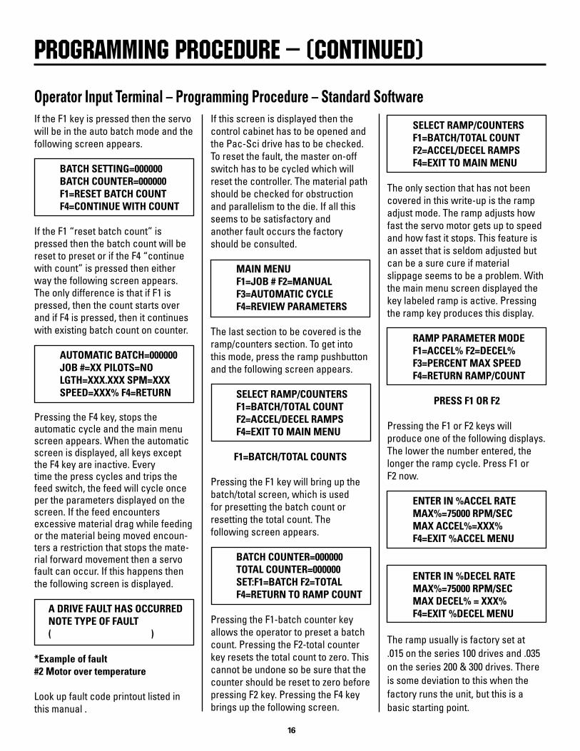
PROGRAmmING PROCEDURE – (CONTINUED)
���
If the F1 key is pressed then the servo will be in the auto batch mode and the following screen appears.
BATCH SETTING=000000 BATCH COUNTER=000000 F1=RESET BATCH COUNT F4=CONTINUE WITH COUNT
If the F1 “reset batch count” is pressed then the batch count will be reset to preset or if the F4 “continue with count” is pressed then either way the following screen appears. The only difference is that if F1 is pressed, then the count starts over and if F4 is pressed, then it continues with existing batch count on counter.
AUTOMATIC BATCH=000000 JOB #=XX PILOTS=NO LGTH=XXX.XXX SPM=XXX SPEED=XXX% F4=RETURN
Pressing the F4 key, stops the automatic cycle and the main menu screen appears. When the automatic screen is displayed, all keys except the F4 key are inactive. Every time the press cycles and trips the feed switch, the feed will cycle once per the parameters displayed on the screen. If the feed encounters excessive material drag while feeding or the material being moved encoun-ters a restriction that stops the mate-rial forward movement then a servo fault can occur. If this happens then the following screen is displayed.
A DRIVE FAULT HAS OCCURRED NOTE TYPE OF FAULT ( )
*Example of fault #2 Motor over temperature
Look up fault code printout listed in this manual .
Operator Input Terminal – Programming Procedure – Standard SoftwareIf this screen is displayed then the control cabinet has to be opened and the Pac-Sci drive has to be checked. To reset the fault, the master on-off switch has to be cycled which will reset the controller. The material path should be checked for obstruction and parallelism to the die. If all this seems to be satisfactory and another fault occurs the factory should be consulted.
MAIN MENU F1=JOB # F2=MANUAL F3=AUTOMATIC CYCLE F4=REVIEW PARAMETERS
The last section to be covered is the ramp/counters section. To get into this mode, press the ramp pushbutton and the following screen appears.
SELECT RAMP/COUNTERS F1=BATCH/TOTAL COUNT F2=ACCEL/DECEL RAMPS F4=EXIT TO MAIN MENU
F1=BATCH/TOTAL COUNTS
Pressing the F1 key will bring up the batch/total screen, which is used for presetting the batch count or resetting the total count. The following screen appears.
BATCH COUNTER=000000 TOTAL COUNTER=000000 SET:F1=BATCH F2=TOTAL F4=RETURN TO RAMP COUNT
Pressing the F1-batch counter key allows the operator to preset a batch count. Pressing the F2-total counter key resets the total count to zero. This cannot be undone so be sure that the counter should be reset to zero before pressing F2 key. Pressing the F4 key brings up the following screen.
PROGRAmmING PROCEDURE – (CONTINUED)
SELECT RAMP/COUNTERS F1=BATCH/TOTAL COUNT F2=ACCEL/DECEL RAMPS F4=EXIT TO MAIN MENU
The only section that has not been covered in this write-up is the ramp adjust mode. The ramp adjusts how fast the servo motor gets up to speed and how fast it stops. This feature is an asset that is seldom adjusted but can be a sure cure if material slippage seems to be a problem. With the main menu screen displayed the key labeled ramp is active. Pressing the ramp key produces this display.
RAMP PARAMETER MODE F1=ACCEL% F2=DECEL% F3=PERCENT MAX SPEED F4=RETURN RAMP/COUNT
PRESS F1 OR F2
Pressing the F1 or F2 keys will produce one of the following displays. The lower the number entered, the longer the ramp cycle. Press F1 or F2 now.
ENTER IN %ACCEL RATE MAX%=75000 RPM/SEC MAX ACCEL%=XXX% F4=EXIT %ACCEL MENU
ENTER IN %DECEL RATE MAX%=75000 RPM/SEC MAX DECEL% = XXX% F4=EXIT %DECEL MENU
The ramp usually is factory set at .015 on the series 100 drives and .035 on the series 200 & 300 drives. There is some deviation to this when the factory runs the unit, but this is a basic starting point.
���
Every servo feed has an eccentric adjustment screw to adjust the upper roller to be in parallel to the lower roller. The maximum adjustment is .008” on the eccentric.
The adjustment screw is located behind the belt cover and is held fast by a 10-32 socket head cap screw. The actual adjustment screw is a slotted eccentric pin which is turned clockwise or counter-clockwise to raise or lower one end of the upper roll.
The parallel adjustment is factory set when the unit is manufactured but if material tracking seems to be a problem then this could be a way of solving the problem. To test if the rolls need adjustment, do the following.
1. Remove the front and rear roll covers.
2. Raise the anti-backup rolls. (If any) main rolls should be closed.
DRIVE ROll PARAllElISm ADjUSTmENT
Drive Roll Parallelism Adjustment Procedure3. Shine a light from the rear of the feed toward the main rollers.
4. Inspect from the main rolls side to see if the rollers are parallel. If they are then the material could be the cause of the material walking. If they are not parallel then an adjustmet has to be made.
5. To make the adjustment: a. Remove manual roll release arm by removing roll pin. b. Remove belt cover. c. Locate eccentric screw and loosen 10-32 screw. d. Turn slotted eccentric screw while viewing rolls until the rolls are parallel. e. Tighten 10-32 screw and reassemble parts, then retry running material.
For a more accurate adjustment use a feeler gage to check the parallelism.
This completes the eccentric adjust-ment write-up. If there are further questions, please call the factory.
NOTE: Before attempting to solve a possible roll parallelism problem by readjusting the rolls or calling the factory, the following test should be performed.
Step one: A 3 to 5 foot length of material should be cut from the storage loop preceeding the servo feed.
Step two: Lay the material next to a straight line to see if the material is cambered. If it is then this could be the reason that the material is walking. If not, then turn the material upside down from the way it was being fed and insert into the feed. If the material walksin the opposite direction then the material could be to blame.

���
No power indication
No display on operator’s console
Power on – no motion
No roll action
Material will not enter rolls
Material will not feed
Material feeds short
Material feeds long
Material camber
Material feeds off center
No automatic cycle
Servo squeals while stopped
Fault signal on Pac-Sci is displayed
Cannot program unit from display
Mechanical pilot release sticks down
TROUblEShOOTING
Problem Cause Remedy– 120 vac circuit tripped– Blown fuse– Master button off
– Program fault– Faulty wiring
– Program fault– Drive fault– Program error
– No air– Low air pressure– Plugged air muffler
– Feed roll adjusting mechanism too close– Material too thick
– Low roller force– Oily material– Program fault– Obstruction in die
– Accel to fast– Low roller force– Oily material– Obstuction in die– Feed signal to close to pilot release
– High % max. speed– Material slippery– Decell set too fast
– High roller force– Bad stock
– Edge guides not set properly– Material not centered to feed– Bad material
– No press signal– Controller fault– Servo fault– Program error
– Servo velocity gain too high– Belt too loose or tight
– Servo fault– Material jam– Power surge/failure
– Program fault– Data Instruments interface jumper loose
– Too much overtravel– Broken spring– Needs lube
– Reset CB– Check/replace fuse– Turn master button on
– Check lights on drive– Check plug on console
– Check lights on drive– Check lights on servo drive readout– Check parameters
– Check air line– Check air regulator– Clean muffler
– Open adjustment mechanism– Check servo parameters
– Raise roller pressure– Clean material– Check parameters– Check die
– Lower accel speed– Raise roller pressure– Clean material– Check die– Move feed signal input so rolls are close to feed
– Lower % max. feed speed– Lower % decel– Lower % decel
– Lower roller pressure– Check stock at input for camber
– Set edge guides– Center material– Try new roll of material
– Check limit switch input to servo control– Check lights on drive– Check lights on drive– Check parameters on display
– Consult factory– Re-adjust belt tension
– Recycle power– Check die – recycle power– Check – recycle power
– Check Pac-Sci and call factory– Check Data Instruments connection
– Restrict travel of mechanical actuating arm– Remove plate and check springs– Remove plate and lubricate release bar

���
The Pacific Scientific drive has a list of internal faults and displays the number of that fault on it’s readout located on the front of the drive. Rapid Air now displays the fault on the keypad display. If a fault occurs the screen will display the number and the name of the fault, but there will not be an explanation
TROUblEShOOTING
Servo Fault Displayaccompanying the fault. This is a tool to help you to troubleshoot if the servo fails to perform when commanded.
If a fault was displayed the servo con-troller will have to be turned off and re-started to clear the fault. If the fault is still present when the Pacific Scientific unit is restarted, the fault may not be
displayed on the keypad screen as the fault will not let the internal program restart. The control panel will have to be opened to view the fault again.
A list of probable faults and some explanation is included in this section. If more help is required, then Rapid Air will have to be contacted.
��0
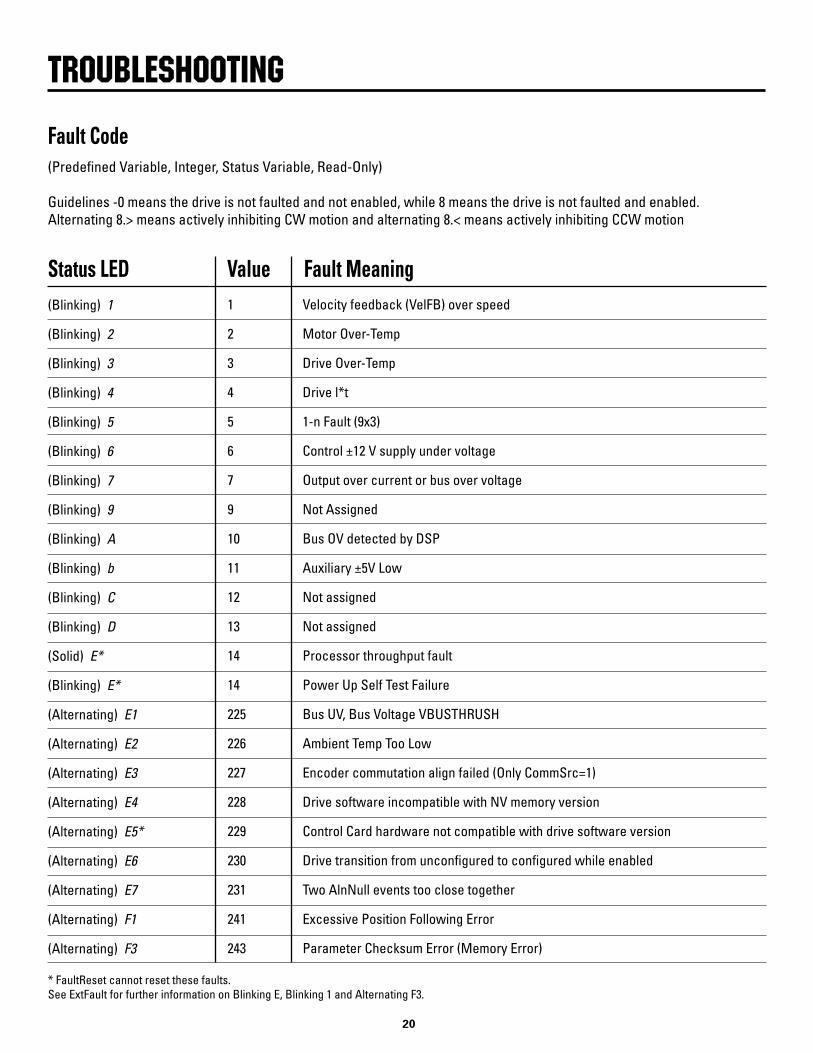
(Predefined Variable, Integer, Status Variable, Read-Only)
Guidelines -0 means the drive is not faulted and not enabled, while 8 means the drive is not faulted and enabled. Alternating 8.> means actively inhibiting CW motion and alternating 8.< means actively inhibiting CCW motion
TROUblEShOOTING
Fault Code
(Blinking) 1
(Blinking) 2
(Blinking) 3
(Blinking) 4
(Blinking) 5
(Blinking) 6
(Blinking) 7
(Blinking) 9
(Blinking) A
(Blinking) b
(Blinking) C
(Blinking) D
(Solid) E*
(Blinking) E*
(Alternating) E1
(Alternating) E2
(Alternating) E3
(Alternating) E4
(Alternating) E5*
(Alternating) E6
(Alternating) E7
(Alternating) F1
(Alternating) F3
Status LED Value Fault Meaning1
2
3
4
5
6
7
9
10
11
12
13
14
14
225
226
227
228
229
230
231
241
243
Velocity feedback (VelFB) over speed
Motor Over-Temp
Drive Over-Temp
Drive l*t
1-n Fault (9x3)
Control ±12 V supply under voltage
Output over current or bus over voltage
Not Assigned
Bus OV detected by DSP
Auxiliary ±5V Low
Not assigned
Not assigned
Processor throughput fault
Power Up Self Test Failure
Bus UV, Bus Voltage VBUSTHRUSH
Ambient Temp Too Low
Encoder commutation align failed (Only CommSrc=1)
Drive software incompatible with NV memory version
Control Card hardware not compatible with drive software version
Drive transition from unconfigured to configured while enabled
Two AlnNull events too close together
Excessive Position Following Error
Parameter Checksum Error (Memory Error)
* FaultReset cannot reset these faults.See ExtFault for further information on Blinking E, Blinking 1 and Alternating F3.
���
The servo motor is flanged mounted and secured with four socket head cap screws. The motor removal has to be done in the sequence described below.
1) The exit side roll guard should be removed. The reason for this will become evident when reassembly of the handle to the shaft is being accomplished.
2) The motor release handle has to be removed. The inner roll pin holds the handle to the shaft. The roll pin has to be driven out as it is a very tight fit. Once this is removed then the handle should slide off the shaft.
OPERATIONAl mAINTENANCE PROCEDURES
Motor Service3) The belt guard has to be removed. It is fastened with four 1/4-20 socket head cap screws.
4) Remove the belt tension by loosening the 2 motor bracket screws and let the motor slide down to the bottom of the slot in the bracket. Remove the motor belt and then the motor.
5) The new motor should already have the belt sheeve installed, so exchange the motors on the mounting bracket.
6) Reassemble the unit in reverse order of the previous instructions.
7) When reinstalling the belt, the tension on the belt should be 1/64” deflection per 1 inch distance be- tween the center line of the pulleys using 1.5 to 2 lbs. force to cause the deflection. Tension the belt so that there is no slack and then run the servo feed for a few cycles. If you get a high belt vibration which causes the servo unit to hum loudly when the unit is sitting idle after a feed, then the tension will have to be readjusted by either tightening or loosening the belt. This operation may have to be performed 2 to 3 times to get it right. Once the servo is running satisfactorily, this operation will not have to be performed again.
At this stage of disassembly, all field maintenance components are exposed and easily accessible. No further field service should be necessary on the roller and gear box
Roller And Gear Box Assemblyassembly unless the gear train is suspected of a malfunction. The drive rolls should be checked for erroneous wear pattern while they are exposed and cleaned before reassembly.
DAILY: a) Wipe off feed rolls. b) Clean any dirt from servo unit. c) Clean any dirt from operators keypad.
WEEKLY: a) Check wear pattern of rolls.
MONTHLY: a) Check oil level (100C). b) Check cables for cuts or wear.
Maintenance Procedures
���
Prior to assembly, attention must be given to points of contact that require an application of Moly-Cote, Lubri-plate or other suitable heavy grease. The points are:
1. The main roll piston and the spiral pins in the main roller tie plate which can be seen by viewing straight down through the center
OPERATIONAl mAINTENANCE PROCEDURES
Reassembly Of Unit of the feed at approximately half way from the inlet to the exit roller. The piston is positioned horizontally at the base of the feed and approximately in the center of the feed if viewing from the gear box to the belt cover.
2. The mechanical roll release shaft located at the exit side of the feed.
Three screws have to be removed and then the keeper plate can be removed. The inner shaft should be thoroughly greased to prevent sticking. Do not apply excessive grease as it may fall onto the drive rollers and cause misfeeding due to material slippage. All bearings are sealed and need no additional lubrication.
The gear box oil must be kept up to sight gauge level and changed after ev-ery 2000 hours of use. Recommended oil is Mobil #SHC630 or equivalent. The oil reservoir capacity is 3.5 oz. The oil can be drained by removal of the drain plug located near the base of the gear housing cover, just below the sight
Lubrication (100C only, 100D no oil bath)gauge. The oil reservoir is filled through the pipe thread port occupied by the air breather plug near the upper edge of the gear housing cover.
NOTE: The original break-in oil in the gear box should be changed after 100 hours of cycle time and examined for
chips or foreign matter. Replace the gear box oil per instructions.
PINCH ROLL ACTUATING PISTONS Periodically grease with lubriplate or equivalent grease to pinch roll actuat-ing piston nose where it contacts the pressure plate.
���
NEVER – Put screwdrivers or foreign materials in feed rolls NEVER – Hold onto material as it is being fed through the servo NEVER – Wear neckties around the servo feed rolls NEVER – Force the rolls open by prying on them NEVER – Modify the mechanical aspects of the servo feed CAUTION – Contact the factory before drilling any holes in the unit CAUTION – Wear proper eye protection when working around the servo CAUTION – Do not wear loose clothing around the servo feed rolls
PRECAUTIONS & SAFETy
Precautions & safety
���
ALL SALES BY THE COMPANY ARE MADE SUBJECT TO THE FOLLOWING TERMS AND CONDITIONS. PLEASE READ.
WARRANTY - The Company warrants, for a period of one year from date of shipment by the Company, that the product shipped is free from defects in material and workmanship. THIS WARRANTY IS EXCLUSIVE AND IN LIEU OF ALL IMPLIED WARRANTIES IN LAW, INCLUDING MERCHANT – ABILITY. The Company obligation under this warranty is limited to repairing or replacing, F.O.B. Madison, SD, any part or parts proved to have been defective when shipped. In no event shall the Company be liable for special or consequential damages. Provisions set forth in specifications are descriptive and subject to change and are not intended as warranties.
Customer License AgreementRapid-Air reserves the rights in its software. The software program is licensed by Rapid-Air to the original purchaser of the equipment which contains the software for use only on the terms set forth in this license.
You may use the program only on the programmable servo computer furnished with the system and only in conjunction with the servo feed supplied with the system.
You may not without expressed permission from Rapid-Air: A. Copy, distribute, or document the program for others. B. Modify or merge any portion of the program for use on non compatible hardware. C. Make alterations to the program.
wARRANTy
Warranty Terms & Conditions
���
���
���
���
���
��0
���
���
���
���

���

���
���